1
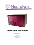
DRS-36 User Manual Digital Reference Selection Board For the Digital Lynx Acquisition System Neuralynx, Inc. 105 Commercial Drive, Bozeman, MT 59715 Phone 406.585.4542 • Fax 406.585.9034 www.Neuralynx.com Revision 12/19/2011 [email protected] Table of Contents Table of Figures .................................................................................................................. 3 1 Document Revision History........................................................................................ 4 2 Document Overview ................................................................................................... 4 3 DRS-36 Overview ....................................................................................................... 4 4 Glossary ...................................................................................................................... 5 5 Reference Signal Concepts ......................................................................................... 6 6 Hardware Overview .................................................................................................... 7 6.1 Headstage Input Signals ....................................................................................... 7 6.1.1 Headstage Power ........................................................................................... 7 6.1.2 Headstage Stimulus ....................................................................................... 7 6.1.3 Animal Ground as a Reference Signal .......................................................... 7 6.1.4 Panel Ground as a Reference Signal ............................................................. 8 6.2 Reference Bus Block Diagram ............................................................................. 8 6.2.1 8 References per DRS-36.............................................................................. 8 6.2.2 Global Reference Bus (GRB) ....................................................................... 9 6.3 Headstage Input Signal Switching to the Reference Bus ..................................... 9 6.4 8 Local Reference Bus Signals to use as 32 Channel References ...................... 10 6.5 Connection to the Input Boards .......................................................................... 10 6.6 Front Panel Lights .............................................................................................. 10 7 Board and Parts ......................................................................................................... 12 8 Connectors ................................................................................................................ 13 8.1 Headstage Input .................................................................................................. 13 8.2 Global Reference Bus Connector ....................................................................... 14 8.3 Differential Output Connector ........................................................................... 15 8.4 Internal Single Ended Monitor Connector ......................................................... 17 9 Global Reference Bus Cable ..................................................................................... 18 9.1 Global Reference Module .................................................................................. 19 9.2 Headstage Modifications .................................................................................... 20 9.3 Communications Path from Cheetah.................................................................. 21 10 Board Numbering and Input Board A/D Numbers ................................................... 21 11 Switching Options ..................................................................................................... 22 12 User Interface in Cheetah.......................................................................................... 22 13 Configuration File Commands .................................................................................. 22 14 DRS-36 Serial ASCII commands ............................................................................. 22 15 Installation................................................................................................................. 23 16 10X differential Amp Section and Internal Monitor Output Connector .................. 26 17 INA 10X Gain Section .............................................................................................. 26 Neuralynx, Inc. 105 Commercial Drive, Bozeman, MT 59715 Phone 406.585.4542 • Fax 406.585.9034 www.Neuralynx.com Revision 12/19/2011 [email protected] Page 2 Table of Figures Figure 6-1 Block Diagram of DRS ..................................................................................... 8 Figure 6-2 Headstage Input ................................................................................................. 9 Figure 6-3 LRB Signals .................................................................................................... 10 Figure 7-1 DRS Board ...................................................................................................... 12 Figure 8-1 Headstage Pinout ............................................................................................. 13 Figure 8-2 LRF Connector ................................................................................................ 14 Figure 8-3 80 Pin Differential Output ............................................................................... 16 Figure 8-4 Monitor Output................................................................................................ 17 Figure 9-1 Global Reference Cable .................................................................................. 18 Figure 9-2 Global Reference Cable Pinout ....................................................................... 19 Figure 9-3 Global Reference Module ............................................................................... 19 Figure 9-4 Slide next Global Reference Module into Previous ........................................ 20 Figure 9-5 Connect Global Reference Module to DRS Board ......................................... 20 Figure 15-1 Blue Jumper Placement ................................................................................. 24 Figure 15-2 Dip Switch Location ..................................................................................... 25 Neuralynx, Inc. 105 Commercial Drive, Bozeman, MT 59715 Phone 406.585.4542 • Fax 406.585.9034 www.Neuralynx.com Revision 12/19/2011 [email protected] Page 3 1 Document Revision History 10/19/2010 Rev 1.2 12/01/2011 Rev 1.3 A section has been included to make sure a secure connection is made with the GRB Cable. (6.2.2) Section 6.2.2 edited to include reference to Global Reference Modules. Section 9.1 added containing information in Global Reference Modules. 2 Document Overview This document will describe Digital Reference Selection for 36 channel headstage preamplifiers (DRS-36) hardware, features and installation. It will also cover concepts and strategies for effective DRS-36 use including how Cheetah software is used to control the board and other advanced software features. The Global Reference Bus Cable and other miscellaneous features of the board are also covered. This document is intended for all users of the Neuralynx Digital Lynx data acquisition system. 3 DRS-36 Overview The DRS-36 offers flexibility and precise control of neural electrode input reference signal selection. This includes the ability to manage and control a pool of reference electrodes, which ideally contains only error, noise and artifact signals. Each channel of a data acquisition system consists of a signal and reference inputs. The Digital Lynx Input Board performs the “signal minus reference” subtraction function in hardware. The DRS-36 allows the user to use any electrode signal as a reference for any other Digital Lynx Input Board input channel. The DRS-36 supports one HS-36 headstage pre-amplifier, 8 reference signals, connection to a Digital Lynx Input Board (32 differential channels), and 8 Global Reference signals which can be shared between multiple DRS-36 boards in a single Digital Lynx system. Neuralynx, Inc. 105 Commercial Drive, Bozeman, MT 59715 Phone 406.585.4542 • Fax 406.585.9034 www.Neuralynx.com Revision 12/19/2011 [email protected] Page 4 4 Glossary The following terms will be used throughout this document. DRS-36 – Digital Reference Selection for 36 channel headstage pre-amplifiers Digital Lynx – Data acquisition system that a DRS-36 is installed into. Input Board – 32 channel, 24 bit data acquisition board that fits in a Digital Lynx slot alongside other Input Boards or DRS-36s. Reference Signal – The signal that is subtracted from the desired electrode signal to reduce the amplitude of noise, artifact and other signals that are part of the desired electrode signal. The reference electrode is usually placed in a quiet part of the brain or a ground screw in the skull. CMRR – Common Mode Rejection Ratio is a measurement based on the amount of residual signal left (error) after the reference signal is subtracted from the desired electrode signal. This is a ratio measurement and usually measured in decibels or as the amount of reduction of the common mode signal (on both the input and reference). A measurement ratio of 10,000:1 is also 80db. Decibels (db) – A logarithmic measurement of two signals with the function: 20 * log10( V1 / V2) Global Reference – A reference signal that is shared between all DRS-36 boards. Global Reference Bus (GRB) – 8 Global Reference signals shared between the DRS-36 boards. Global Reference Bus Cable – The cable that connects the Global Reference signals between the DRS-36 boards. Local Reference – A signal on the DRS-36 board which is used as a reference signal output. This signal may come from a headstage signal or a GRB input. Local Reference Bus (LRB) – The bus of 8 signals which can be used as the output channels’ reference signal. Headstage – A unity gain low noise buffer amplifier usually placed close to the recording site of an electrode. Headstage Signals – These are the buffered electrode signals from the unity gain amplifier mounted on the animal. They are present on the front panel Headstage Connector. Neuralynx, Inc. 105 Commercial Drive, Bozeman, MT 59715 Phone 406.585.4542 • Fax 406.585.9034 www.Neuralynx.com Revision 12/19/2011 [email protected] Page 5 5 Reference Signal Concepts Neural electrodes contain the desired signal plus a combination of undesired noise, error, and artifact signals. A reference electrode signal ideally is void of the desired signal and only consists of the same error, noise and artifact signals. To obtain the clean, noise-free desired signal the reference electrode signal is subtracted from the neural electrode signal, normally with electronics. All Neuralynx data acquisition products boast an excellent Common Mode Rejection Ratio (CMRR) specification on neural inputs (on either the Lynx-8 Amplifier or the Digital Lynx system) of over 100 db; a ratio of 100,000 to 1. This design aspect of Neuralynx hardware provides the basis for low noise recording results. As wiring, PC Board traces, connectors and/or electronics are added to the signal paths the CMRR specification will be degraded due to parasitic capacitances, inductances and circuit resistances. The DRS-36 Common Mode Rejection Ratio measurement is 80db to 77db (10,000:1 to 7,000:1) which is still sufficient for all standard electrophysiology experiment recording. The exception would be in environments with very large signal artifacts, such as an MRI signal artifact or other huge external signal. Neuralynx, Inc. 105 Commercial Drive, Bozeman, MT 59715 Phone 406.585.4542 • Fax 406.585.9034 www.Neuralynx.com Revision 12/19/2011 [email protected] Page 6 6 Hardware Overview 6.1 Headstage Input Signals There are 37 headstage input signals. These are: 32 input channels 4 References (Ref1 -> Ref4) Animal Ground which is an unbuffered non current carrying wire used to connect the headstage ground to the DRS-36 (or ERP-xx) for a reference signal. Note that the DRS-36 will accept connections from the standard Neuralynx Headstage product line (HS-36, HS-27x, HS-18, HS-16) but not all signals and reference signals are present on all headstages. 6.1.1 Headstage Power The headstage power supply outputs +5v and -5v. There is no current limit but the solid state switches will start to limit current around 200 milliamps (in theory). Both power supplies are controlled by a set of 3 solid state PhotoMOS devices in a circuit that will turn on both power supply rails within a millisecond of each other. The circuit is designed to minimize the chance of single supply turn on, which is bad for the opamps and leakage currents on the headstage. 6.1.2 Headstage Stimulus Two differential stimulus channel connections are present from the 3M MDR-26 connector to the Headstage 3M MDR-50 connector. These stimulus channels (Stim1_Src, Stim1_Ret, Stim2_Src and Stim2_Ret) are consistent with all Neuralynx headstages, tethers and ERP-xx products that incorporate stimulus lines. 6.1.3 Animal Ground as a Reference Signal The Animal Ground signal is made by a non-current carrying wire connected to the headstage ground plane through the tether cable and is present on the DRS-36 for use as a reference signal. The theory for this signal is that it is separate from the normal “power ground lines” in the tether. This Animal Ground signal wire carries no current; therefore it should not have any voltage drop along the signal wire and it will be the most faithful representation of the ground voltage on the animal. This signal is useful when adjusting reference electrodes or when active reference electrodes have become damaged or inoperative. This Animal Ground is the same as on other Neuralynx products. Neuralynx, Inc. 105 Commercial Drive, Bozeman, MT 59715 Phone 406.585.4542 • Fax 406.585.9034 www.Neuralynx.com Revision 12/19/2011 [email protected] Page 7 6.1.4 Panel Ground as a Reference Signal Panel Ground is the ground plane signal on the DRS-36 board. It may be used as a reference signal if needed. This is consistent with other Neuralynx products. 6.2 Reference Bus Block Diagram The following figure shows the various switches, buffers and busses used on the DRS-36. The various reference bus sections are always a maximum of 8 signals wide. Headstage 37 input signals Panel Ground GRB Connector 3M MDR-26 Front Panel Input Board Output Connector 32 Diff Output Signals (64 total) 32 Headstage Signals A1->16 and B1->16 GRB signals may be sourced or input 8 GRB Switches Array of 38 Solid State 1:8 multiplexer/switches 8 Refs 8 Controlled Buffer Amps with output enables 8 Local Ref Bus Buffer Amps 8Refs 32 Selected Ref Signals Output Connector – connects to Input Board 32 differential signal connector 8 GRB Front Panel GRB Connector 38 Signals Front Panel Headstage Connector Array of 32 Solid State 8:1 multiplexer/switches 8 Local Ref Bus signals which are used for differential output signal reference selection Selection of possible 8 headstage signals to be used as references Figure 6-1 Block Diagram of DRS 6.2.1 8 References per DRS-36 The DRS-36 supports up to 8 reference signals to be used on the board. This means that the 32 output channels connected to the Digital Lynx Input Board can have 8 different reference signals. This would equate to one reference per 4 channel Tetrode. This has proven to be more than enough for most normal spike and LFP recording setups. The exception would be for EMG differential signals which require one reference for each input channel. For a 32 channel EMG differential recording setup, the 64 signals would be connected directly through the headstages to the Input Boards. A DRS-36 or ERP would not normally be used for this recording setup. The sources for these 8 reference signals include the above mentioned headstage signal, Panel Ground and any of 8 Global Reference Bus signals which allow sharing of references between DRS-36 boards. These 8 reference signals will be referred to as the “Local Reference Bus” signals. Neuralynx, Inc. 105 Commercial Drive, Bozeman, MT 59715 Phone 406.585.4542 • Fax 406.585.9034 www.Neuralynx.com Revision 12/19/2011 [email protected] Page 8 6.2.2 Global Reference Bus (GRB) The Global Reference Bus (GRB) is a set of eight signals connected between DRS boards to allow sharing of reference signals among boards. These signals are connected to the front panel 3M MDR-26 connector. A Global Reference Bus Cable or Global Reference Bus Module is used to connect these signals in parallel between multiple DRS boards in a system. If using the first version of the GRB Cable(Black Connectors), please make sure to securely fasten the connection using the screws on each connector. If using the second version of the GRB Cable(Silver Connectors), please make sure the side clips “clamp” for a secure connection. If using Global Reference Modules make sure they have slid together correctly and are fully inserted into the DRS board. The Global Reference Bus signals are normally derived/driven from individual headstage signals. GRB signals are normally buffered before being driven on to the bus and are buffered again after the front panel connector before being used as Input Board Channel reference signals. This second rebuffering prevents the parasitic capacitance of the solid state switches used on the DRS from loading the signal lines and degrading the signal . 6.3 Headstage Input Signal Switching to the Reference Bus The 38 headstage signals (32 + 4ref + Agnd + PGnd) each have a “1 to 8” solid-state multiplexer/switch integrated circuit device. This switch chip has a common input (which is the headstage signal input) and 8 outputs, one of which may be “switched” to the input. There is also an “enable” switch which is used to disconnect the headstage signal from all of the 8 local reference bus signal lines. Figure 6-2 Headstage Input The 8 output pins from the 38 multiplexer chips are tied in common to the 8 respective Local Reference Bus signals. This design allows any headstage signal to be connected to any Local Reference Bus signal. Note that the enable switch feature in the multiplexer chip allows a “no connect” for the headstage signal. The intelligence on the DRS-36 board will allow only one headstage signal to be connected to any individual Local Reference Bus signal line. Neuralynx, Inc. 105 Commercial Drive, Bozeman, MT 59715 Phone 406.585.4542 • Fax 406.585.9034 www.Neuralynx.com Revision 12/19/2011 [email protected] Page 9 6.4 8 Local Reference Bus Signals to use as 32 Channel References The same 8:1 Multiplexer IC is used to individually select one of the 8 Local Reference Bus signals (LRB) for each of the 32 output channels’ reference signals. Figure 6-3 LRB Signals Remember that the output of the DRS-36 connects directly to the input of the Digital Lynx Input Board (AC or DC coupled versions). There are 32 differential inputs on the Input Board (and 32 differential outputs on the DRS-36) and each channel has a Signal (+) and a Reference (-). The eight inputs on the left connect to the LRB and the “Common” pin on the right connects to an output channel’s reference signal. The output Enable Switch shown is set to be closed (enabled). 6.5 Connection to the Input Boards The connection of the 32 differential output channels to the Input Board is normally done with a short 80 pin dual ribbon cable jumper. The output connector is a high density 80 pin connector, the same part as the Input Board’s differential input connector, with the exception that the DRS-36 connector is mirrored from the Input Board’s connector to allow the use of this simple cable to make the connection. 6.6 Front Panel Lights There are four recessed LEDs on the top section of the DRS-36 which are viewable from the front. These top four LEDs indicate the status of the four supplies. From top to bottom these LEDs indicate: +5v Headstage Power -5v Headstage Power Neuralynx, Inc. 105 Commercial Drive, Bozeman, MT 59715 Phone 406.585.4542 • Fax 406.585.9034 www.Neuralynx.com Revision 12/19/2011 [email protected] Page 10 +5v Board Analog Power -5v Board Analog Power A blue LED in the center of the board labeled HSPwr indicates when the +/- 5v headstage power is supplied to the headstage connector. The bottom section of the board contains five recessed LEDs which indicate: Boot – to show that the board has been properly initialized Accs – to indicate that the last DRS-36 command was processed by this board Error – to indicate that a DRS-36 Serial String command contained an error D4 – a reserved status indicator D5 – a reserved status indicator Note that an error does not indicate a failure condition unless it stays lit during system boot up or a time when many reference signal changes are made (from the Cheetah User Interface). Neuralynx, Inc. 105 Commercial Drive, Bozeman, MT 59715 Phone 406.585.4542 • Fax 406.585.9034 www.Neuralynx.com Revision 12/19/2011 [email protected] Page 11 7 Board and Parts The following picture shows the major components of the DRS-36. Figure 7-1 DRS Board Neuralynx, Inc. 105 Commercial Drive, Bozeman, MT 59715 Phone 406.585.4542 • Fax 406.585.9034 www.Neuralynx.com Revision 12/19/2011 [email protected] Page 12 8 Connectors 8.1 Headstage Input The Headstage Input Connector is the standard 3M 50 pin MDR connector used throughout other Neuralynx ERP-xx patch panels and the Digital Lynx Input Board. The wiring on this connector uses 32 input signal pins and 4 input reference signals, as well as the standard headstage power, animal ground and two differential stimulus channels. The wiring on this connector is a superset of signals and will support all Neuralynx headstages. Figure 8-1 Headstage Pinout Neuralynx, Inc. 105 Commercial Drive, Bozeman, MT 59715 Phone 406.585.4542 • Fax 406.585.9034 www.Neuralynx.com Revision 12/19/2011 [email protected] Page 13 8.2 Global Reference Bus Connector The Global Reference Bus connector is a 3M 26 pin MDR connector; a smaller version of the Headstage Input connector. This connector has the 8 Global Reference Signals, 8 ground connections, Headstage +/-5v power (switched on and off with the headstage power) and external connections for the two differential Stimulus Channels (4 wires total). The Stimulus Channels are present on this connector to allow connections from Stimulus Isolation Units to stimulus electrodes connected to the EIB or power signals for lighting video tracker LEDs mounted to the headstage. The operation of the Stimulus Channel connections is the same as with all of the Neuralynx ERP-xx patch panels, which is that there are no electronic connections to these lines and there is a continuous connection from the ERP-xx or DRS-36 from the input connector through the tether and headstage through to the Electrode Interface Board mounted on the animal or microdrive. The Global Reference Bus Cable will have the standard 10 pin connector mounted on a short wired connection. Figure 8-2 LRB Connector Neuralynx, Inc. 105 Commercial Drive, Bozeman, MT 59715 Phone 406.585.4542 • Fax 406.585.9034 www.Neuralynx.com Revision 12/19/2011 [email protected] Page 14 Note that the Stimulus Channel lines can be used for two purposes: 1) to deliver stimulus current to the animal; and 2) to power the Video Tracker LEDs on a headstage. If your experiments or laboratory use both Video Tracker LEDs and direct brain current stimulation you MUST make sure that the Stimulation Channels do NOT have the video tracker LEDs power supplied to stimulation electrodes in the brain. This can cause a large lesion. 8.3 Differential Output Connector The output signal connector has lines for the 32 differential output signals and 16 ground wires. This connector has a mirrored pinout of the Digital Lynx Input Board input connector to allow a simple 80 pin jumper cable to be used to connect the DRS-36 output to the Input Board. Neuralynx, Inc. 105 Commercial Drive, Bozeman, MT 59715 Phone 406.585.4542 • Fax 406.585.9034 www.Neuralynx.com Revision 12/19/2011 [email protected] Page 15 Figure 8-3 80 Pin Differential Output Neuralynx, Inc. 105 Commercial Drive, Bozeman, MT 59715 Phone 406.585.4542 • Fax 406.585.9034 www.Neuralynx.com Revision 12/19/2011 [email protected] Page 16 8.4 Internal Single Ended Monitor Connector Figure 8-4 Monitor Output Neuralynx, Inc. 105 Commercial Drive, Bozeman, MT 59715 Phone 406.585.4542 • Fax 406.585.9034 www.Neuralynx.com Revision 12/19/2011 [email protected] Page 17 9 Global Reference Bus Cable Figure 9-1 Global Reference Cable The Global Reference Bus (GRB) Cable connects two or more boards’ GRB connectors in parallel so that reference signals may be shared between DRS-36 and headstages. Each GRB connector on the cable also has a 10 pin connection for the Headstage Stimulus Channel signals. The schematic is shown for a two connector GRB cable. Neuralynx, Inc. 105 Commercial Drive, Bozeman, MT 59715 Phone 406.585.4542 • Fax 406.585.9034 www.Neuralynx.com Revision 12/19/2011 [email protected] Page 18 Figure 9-2 Global Reference Cable Pinout 9.1 Global Reference Module Figure 9-3 Global Reference Module The Global Reference Module is an expandable version of the Global Reference Cable. It connects two or more GRB connectors in parallel so that reference signals may be shared Neuralynx, Inc. 105 Commercial Drive, Bozeman, MT 59715 Phone 406.585.4542 • Fax 406.585.9034 www.Neuralynx.com Revision 12/19/2011 [email protected] Page 19 between DRS-36s and headstages. Each Global Reference Module contains a standard 0.1" pitch 2x5 connector allowing access to the Headstage Stimulus Channels and Headstage Power Rails. The pinout matches the 10 pin connector on the Global Reference Cable. When connecting multiple Global Reference Modules to a Digital Lynx begin by connecting a Global Reference Module to the last(right most) DRS board. Next, work your way left sliding the next Global Reference Module into the card edge socket of the previous module while connecting it to the next DRS board. Sliding it into the previous module at a slight angle will make this easier. Refer to the figures below. Figure 9-4 Slide next Global Reference Module into Previous Figure 9-5 Connect Global Reference Module to DRS Board 9.2 Headstage Modifications Recently, a new revision of the Neuralynx Headstages was released with a modified board layout of the Stimulation and Video Tracking traces. In the past, a stimulation plug was needed to power all Video Tracking LED’s on the Headstages. The HS-36 and the HS-18 Cooner were modified so that this plug is no longer needed. If you have an Neuralynx, Inc. 105 Commercial Drive, Bozeman, MT 59715 Phone 406.585.4542 • Fax 406.585.9034 www.Neuralynx.com Revision 12/19/2011 [email protected] Page 20 older revision Headstage, please continue to use the stim plugs as before. Please refer to Table 1 for reference. Table 1 Headstage (HS) STIM Plug Requirements for Video Tracking LED’s HS-36 HS-27 HS-18 Cooner/FWT HS-36 STIM Plug needed HS-27 STIM Plug Needed HS-36 STIM Plug needed on Revision 2.0 or earlier on all HS’s on Revision 2.0 or earlier 9.3 Communications Path from Cheetah As of January 20, 2007 there is a known bug in the communications path from the fiber optic cable to the high speed serial receiver (MGT) on the Digital Lynx Motherboard. This bug causes about 1 in 5000 bytes to be lost or damaged. Each DRS-36 command packet consists of 12 characters (and 96 fiber optic cable bytes) so about 1 in 300 commands will experience an error. The format of the DRS-36 commands has been designed so that any missing character will be detected as an error. All DRS-36 commands are sent twice from the Cheetah Software to make sure that a damaged command packet will be received at least once (either by the first or second command packet). 10 Board Numbering and Input Board A/D Numbers The Digital Lynx cabinet contains 10 board slots which are populated with Input Boards, DRS-36s or a blank slot filler. These board positions are numbered from left to right; B0 through B9. Board Slot #0 MUST be populated with an Input Board. Remember that the first A/D input on a board is A/D #0. The A/D input channel numbering is based on Board Slot number and the channel number of the Input Board with the equation: A/D_Channel = (Board# * 32) + Input_Number. For example Channel #15 on board in slot B2 would be 79. 79 = (2 * 32) + 15. Normally the DRS-36 is inserted to the right of the Input Board it is connected to. A 64 channel system would have a hardware board configuration of Input-Board (Slot B0), DRS-36 (Slot B1), Input-Board (Slot B2), DRS-36 (Slot B3). Therefore the two InputBoards will have the A/D channels of 0->31 and 64->95. Neuralynx, Inc. 105 Commercial Drive, Bozeman, MT 59715 Phone 406.585.4542 • Fax 406.585.9034 www.Neuralynx.com Revision 12/19/2011 [email protected] Page 21 11 Switching Options The DRS-36 has the following Signal Switching functions: Any of the 37 Headstage Signals may be used as any of the 8 LRB Signals; Any of the 8 external GRB Inputs may be used as the LRB signals. The GRB signals have a restriction in that each GRB signal may be used as the respective (corresponding) LRB signal. For example; GRB3 may only be used as LRB3. Any individual LRB signal may be driven by either a headstage signal or by a GRB signal, but not by both. Any LRB signal originating from the Headstage may be driven out to the GRB connector and used by other boards through their GRB connector. Each of the 32 Output Channels’ reference signal may be selected from any of the 8 LRB signals. These rules have been implemented in the Cheetah DRS-36 User Interface Control Panel. 12 User Interface in Cheetah The Cheetah Software version 4.95.20070112 or later must be used with the DRS-36. This version has a new window with the DRS-36 controls. Current versions of the Cheetah Software (5.0.0 and higher) include a complete Cheetah Reference Guide, accessible through the Help menu, which fully document the DRS user interface. 13 Configuration File Commands The DRS settings are saved in configuration files for use in future Cheetah recording sessions. The commands and syntax are documented in the Cheetah Reference Guide, accessible through the Help menu in Cheetah. DRS Commands are found under Cheetah Commands in the Cheetah Reference Guide index. 14 DRS-36 Serial ASCII commands The serial ASCII command strings can be used to control the DRS-36 with Cheetah configuration or NetCom commands. If this is done the changes will not be reflected in the User Interface. This operation is not recommended. Contact Neuralynx Technical Support if the low level Serial ASCII strings are needed. For Technical Support email [email protected] Neuralynx, Inc. 105 Commercial Drive, Bozeman, MT 59715 Phone 406.585.4542 • Fax 406.585.9034 www.Neuralynx.com Revision 12/19/2011 [email protected] Page 22 15 Installation The following steps are required to install and use the DRS-36 in the Digital Lynx system with the Cheetah Software. 1) Place the DRS-36 and Input Boards in the Digital Lynx cabinet. This will usually consist of an Input Board followed by a DRS-36 board, for the number of Input Boards in your system. For example if you have 128 channels on 4 Input Boards your cabinet will have: Slot 0 Input Board Slot 1 DRS-36 Slot 2 Input Board Slot 3 DRS-36 Slot 4 Input Board Slot 5 DRS-36 Slot 6 Input Board Slot 7 DRS-36 Slot 8 Empty Slot Cover Slot 9 Empty Slot Cover 2) Replace the Flash Card in the System Ace board, found behind the rear cover of the Digital Lynx interface box, with the Flash Card supplied. 3) Move the Blue Jumper Wire, to define the number of boards in the Xilinx programming string (the source of the programming is from the Flash Card in the above step) as shown in the table below: Total Input and DRS-36 boards Blue Wire Connector Position 1 - not valid as this would be only for 1 input board and no DRS-36 2 - 1 IB and 1 DRS 14 3 - IB DRS IB 13 4 - IB DRS IB DRS 12 5 - IB DRS IB DRS IB 11 6 - IB DRS IB DRS IB DRS 10 7 - IB DRS IB DRS IB DRS IB 9 8 - IB DRS IB DRS IB DRS IB DRS 8 9 - IB DRS IB DRS IB DRS IB DRS IB 7 10 - IB DRS IB DRS IB DRS IB DRS IB DRS 6 Neuralynx, Inc. 105 Commercial Drive, Bozeman, MT 59715 Phone 406.585.4542 • Fax 406.585.9034 www.Neuralynx.com Revision 12/19/2011 [email protected] Page 23 Figure 15-1 Blue Jumper Placement Neuralynx, Inc. 105 Commercial Drive, Bozeman, MT 59715 Phone 406.585.4542 • Fax 406.585.9034 www.Neuralynx.com Revision 12/19/2011 [email protected] Page 24 4) Using Table 2 below, set four of the switches on the red DIP switch in the rear of the Digital Lynx Interface Box. This red DIP switch is designated “Config DIP Switch” in the top image of Figure 15-1 on the previous page. Figure 15-2 Dip Switch Location Note that the switch positions from left to right are 1, 2, 3, 4, 5, 6, 7, and 8. To set the number of boards we will use only switches 1, 2, 3 and 4. Use the following table to set the position of each of the 4 switches. Use ONLY switches 1 through 4. Table 2 Red DIP Switch Settings (‘I’ for Input Board, ‘D’ for DRS-36 Board) Sw1 Board Configuration I ID IDID ID x 3 ID x 4 ID x 5 II Ix4 Ix5 Ix6 Ix7 Ix8 Ix9 Up Up Up Up Up Down Up Up Up Up Up Up Down Sw2 Sw3 Sw4 Sw5 Sw6 Sw7 Sw8 Up Up Up Down Down Up Up Up Down Down Down Down Up Up Up Down Up Down Up Up Down Up Up Down Down Up Up Up Up Up Up Up Down Down Up Down Up Down Up Up Up Up Up Up Up Up Up Up Up Up Up Up Up Up Up Up Up Up Up Up Up Up Up Up Up Up Up Up Up Up Up Up Up Up Up Up Up Up Up Up Up Up Up Up Up Up Up Up Up Up Up Neuralynx, Inc. 105 Commercial Drive, Bozeman, MT 59715 Phone 406.585.4542 • Fax 406.585.9034 www.Neuralynx.com Revision 12/19/2011 [email protected] Page 25 I x 10 Down Up Up Down Up Up Up Up 5) Set the NumBoards config file parameter in the Digital_Lynx.cfg file. This should be set to the number of boards in the system. It MUST correspond to the “number of boards” setting of the red DIP Switch above. * In this setting, do not count a DRS board if it is in the last, rightmost slot of the Digital Lynx. 16 10X differential Amp Section and Internal Monitor Output Connector The Monitor Output connector provides user connection to the 32 output channels which are buffered, amplified (10X) and converted to single ended output signals. This Monitor connector mounted on the PC Board and is not accessible on the front panel. These signals can be used for audio or oscilloscope monitoring. This section of the board contains 32 differential Instrumentation Amplifiers, one for each channel with a gain of 10. It is possible to connect a 34 pin ribbon cable to this internal connector and pass the ribbon cable between front panel board segments and use this for your own purposes. Please note that improper use of these signals may induce noise or other artifact into the system. See the section on Connectors for more details. 17 INA 10X Gain Section The Single Ended Output can be used as a monitor output for all 32 differential output put channels. The same instrumentation amplifier (INA2128) used on the Digital Lynx Input Boards are connected to the 32 output channels on this board. These Instrumentation Amplifiers perform the same (Channel - Reference) subtraction functions as on the Input Boards prior to A/D conversion. A Gain of 10 is designed into this section to boost the signal level. The inputs to the amplifier are the same differential connections presented to the input board. The INA2128 inputs are DC coupled (no AC blocking/coupling capacitor) so it is possible to clip the outputs of these amplifiers by presenting a 500 millivolt difference between the signal and the selected reference. Neuralynx, Inc. 105 Commercial Drive, Bozeman, MT 59715 Phone 406.585.4542 • Fax 406.585.9034 www.Neuralynx.com Revision 12/19/2011 [email protected] Page 26