1
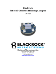
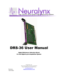
. HS 54 User Manual Revision 2.01: July, 2009 Neuralynx, Inc. 105 Commercial Drive, Bozeman, MT 59715 Phone 406.585.4542 • Fax 406.585.9034 www.Neuralynx.com [email protected] Table of Contents 1 2 3 4 5 6 7 8 9 Document Overview ................................................................................................... 3 Headstage 54 Overview .............................................................................................. 3 Glossary ...................................................................................................................... 4 Tether Signal Connections .......................................................................................... 5 Power Supply Requirements ....................................................................................... 6 Mounting the Headstage to the EIB ............................................................................ 6 Tetrode Adjustment Tool Alignment Cutouts ............................................................ 7 LED’s Power, Usage and Customization.................................................................... 7 Practical Tips .............................................................................................................. 8 9.1 Antistatic Precautions ........................................................................................... 8 9.2 Maintenance and Cleaning Information ............................................................... 8 9.3 Shorting Plug Board description and use ............................................................. 8 10 HS-54/EIB-54/Tether Combination Channel Mapping ............................................ 10 List of Figures and Tables Figure 1 Pinout of the Two uDB37 Tether Connectors ...................................................... 5 Figure 2 Via Labeling on EIB ........................................................................................... 10 Table 1 HS-54 Channel Mapping ..................................................................................... 10 Table 2 HS-54 Reference Mapping .................................................................................. 10 Neuralynx, Inc. HS-54 User Manual Revision 2.01: July 2009 Page 2 1 Document Overview The purpose of this document is to explain the functionality of the HS-54. This will include general information of the Headstage and a chart explaining the mapping of all of the tetrode channels. 2 Headstage 54 Overview This manual should be used with the Neuralynx EIB board-EIB-54 Kopf manual. The Neuralynx Headstage Amplifier is the active electronic part of the Hyperdrive / Electrode Interface Board / Headstage / Tether system. It provides 54 channels of Unity Gain amplification (buffering) and locations for up to 28 surface mount light emitting diodes (for use in experiments, which involve animal position tracking). It also provides connections for the electrode inputs to the EIB and output connectors for the dual cable 72-conductor tether. The Headstage Amplifier is 56 millimeters in diameter. Two 37 pin micro-D connectors are used for tether connections. Four connectors on the bottom of the board are used to connect the Headstage Amplifier to the Neuralynx Tetrode Interface Board. Low noise, low power, low input bias current Opamp have been used on this device instead of the traditional “Source Follower FET circuit” used in the traditional headstage amplifier design in order to: obtain exact unity gain which greatly improves Common Mode Rejection Ratio (CMRR) performance for the entire recording system for artifact and other common mode noise signal rejection; lower output impedance to reduce noise susceptibility of the tether and other signal cabling; provide integral antistatic protection on each input channel; insure low input bias current levels; and eliminate signal distortion. NOTE: Because an Opamp is used for the unity gain buffer amplifiers, special care and attention must be given to the power supply design and power application and removal sequencing. The input protection circuitry will lower the input impedance if the input voltage exceeds either power supply voltage. This can occur by either raising the input voltage signal above the power supply voltage or by the loss of either power supply voltage. In practical use, this is not a problem since the tether connectors make a robust connection and redundant wires are used in the tether for the power supply connections. The 2 power supplies should be applied simultaneously with a double pole (DPDT) switch. The Neuralynx EEG/Reference Panel contains power supplies, which properly sequence power supply voltage and monitor headstage currents. Neuralynx, Inc. HS-54 User Manual Revision 2.01: July 2009 Page 3 3 Glossary EIB – An Electrode Interface Board (EIB) is the interface between experiment electrodes in a microdrive and the appropriate headstage IB – Neuralynx Input Board (AC/DC) DRS – Digital Reference Selector Board Neuralynx, Inc. HS-54 User Manual Revision 2.01: July 2009 Page 4 4 Tether Signal Connections Two 37 pin micro-D type connectors are used for the headstage-tether connections. Tether cables consist of a pair of shielded 36 conductor cables to give a total tether connection of 72 wires with overall shields Signal type assignments (input, output and power) for the two connectors are “identical”, meaning that the same pins on each connector are used for the same type of signal. For example: pin 37 is used for the shield; pin 21 is a reference electrode output. This allows the connectors to be reversed without damage to the Headstage or animal however proper connections must be made or recording channels will be reversed. The individual wires in the Tether are 44 gage stranded conductors with a resistive measurement of approximately 3 ohms per meter. The Shield (pin 37) has a resistance measurement of about 1-ohm total for a 5-meter cable. Figure 1 Pinout of the Two uDB37 Tether Connectors Note: The ground signals on pin 37 and 28 are connected together on the headstage amplifier board. Neuralynx, Inc. HS-54 User Manual Revision 2.01: July 2009 Page 5 5 Power Supply Requirements The Headstage Amp requires a dual supply, +5v and -5v for the buffer Opamp amplifiers. Current draw will be about 15 milliamps. LED power is separate from amplifier power. LED power requirements and operation is described below. NOTE: Care must be taken when powering the Headstage Amplifier. Both +5v and -5v supplies must be applied and removed at the same time. Each tether connector contains conductors for the +5v and -5v amplifier power. This redundancy will result in better reliability and less voltage drop on the power conductors in the tether. 6 Mounting the Headstage to the EIB The EIB is permanently attached to the Hyperdrive. The Headstage Amplifier is mounted to the EIB by placing the Headstage Amplifier on top of the EIB and carefully tightening the hold down screw in the center of the Headstage Amplifier. The alignment block provides proper connector pin alignment between the two boards. In practical daily use, the Alignment Block allows convenient and proper connection even if the animal is moving. This system also allows the Headstage to be removed without damage (bending) to the “double male” signal connection pins used between the Headstage Amplifier and the Tetrode Interface Board. The bottom side of the Headstage Amplifier contains 4 female connectors arranged in a rectangular pattern mirroring the connector pattern on the topside of the EIB. Each board has female socket type connectors to reduce the possibility of damage to the board assemblies. An additional connector set, “double male headers,” are used to make the connections between the two boards allowing for easy replacement of a damaged header connector and proper vertical spacing between the two boards. Note: The header pins should normally be left with the Headstage Amplifier and not with the Electrode Interface Board. As stated above, there are 4 connectors between the Headstage Amplifier and EIB. The front connector is a single row 14 pin connector; the rear connector is a single row 16 pin connector; and the left and right connectors are a double row 18 pin connector with the pins arranged in a 2 x 9 pattern. Note that the 2 dual row left and right connectors have an offset: the left side connector is one pin position to the rear of connector on the right side. Care must be taken to insure that the Headstage Amplifier is attached with the proper front-to-rear orientation. Headstage power should be turned off when connecting and disconnecting to the animal. A spare set of the 4 double male header connectors is included with the Headstage Amplifier. Extra sets of the header connectors may be ordered from Neuralynx. Neuralynx, Inc. HS-54 User Manual Revision 2.01: July 2009 Page 6 7 Tetrode Adjustment Tool Alignment Cutouts There are 14 semi-circular recesses on the outside edge of the Headstage Amplifier printed circuit board. These recesses, or cutouts, accommodate the Tetrode Adjustment Tool and help the user align the tool during insertion and adjustment. Note that each tetrode number (TT1 through TT12) is labeled on each side of the respective tetrodes’ position. The two Reference Electrodes’ adjustment locations are labeled as Ref1 and Ref2. 8 LED’s Power, Usage and Customization Two separate conductors in each Tether (Vled+ and Vled-) are used for LED power with the following benefits: The LEDs can be powered independently from the unity gain buffer amplifier circuitry; LED voltage may be different than the amplifier power voltages; Tether wire voltage drop is reduced since the LEDs will typically draw more current than the unity gain Opamp amplifiers. The LED default pattern consists of single blue LEDs at the front and rear positions, two red LEDs on the left and right adjacent positions of the front blue LED, and two green LEDs on the left and right adjacent positions of the rear blue LED. For this configuration the power supply voltage applied to the Vled+ and Vled- tether connections should be +5v and -5v respectively. Note: These are the same voltages, which are used for powering the amplifier circuitry, and the same power supply may be used for both powering LEDs and the amplifiers. There are a total of 14 LED mounting positions, one between each Tetrode Adjustment Tool Alignment Cutout location. Each of the 14 LED position consists of two surface mount LED mounting pads (a total of 4 pads at each location) on the top side of the board and 2 pads on the bottom side of the board for a single surface mounted LED-series current limiting resistor on the bottom side of the board. The two LEDs and the resistor are connected in series. There are also 4 small via holes between the LED mounting positions. These vias provide connections to: LED positive power voltage; LED negative power voltage; The LED end of the series connected LED-LED-Resistor circuit and The resistor end of the LED-LED-Resistor string. This allows for a very flexible LED configuration. If you need to have a custom LED configuration please contact Neuralynx for advice on the LED mounting and wiring configuration. If you do not need the LEDs you may leave Neuralynx, Inc. HS-54 User Manual Revision 2.01: July 2009 Page 7 them unpowered (off). A good practical use is to power the LEDs along with the amplifier power to indicate power application to the amplifier circuitry. 9 Practical Tips ALWAYS WEAR AN ANTISTATIC WRIST STRAP WHEN HANDLING AN ANIMAL ORWHEN HANDLING THE HEADSTAGE AMPLIFIER. These are available at most electronics stores. It is very convenient to leave the headstage amplifier physically connected to the in between experiment recording sessions. When this is done, protect the headstage by placing it in the black antistatic shipping box. A piece of black conductive foam in the bottom of the box will also help. Keep the double male header connectors attached to bottom side of the Headstage Amplifier and not to the top of the Tetrode Interface Board (attached to the animal). A small amount of heat glue or other removable adhesive can be used to hold the double male header connectors to the bottom side of the Headstage Amplifier. This will help the header connectors stay with the Headstage Amplifier when the animal is disconnected. Remember that you will want to replace the header connectors if one is damaged or bent. 9.1 Antistatic Precautions As with all electronics, static discharges cause damage to semiconductor devices and especially to impedance inputs. The Opamp inputs are protected against a 2000-volt discharge but care must still be used when handling and using the Headstage Amplifier. Please observe the following guidelines: always wear a grounding wrist strap when handling an animal which is connected for recording; always wear a grounding wrist strap when handling the Headstage Amplifier; and Store the headstage in the black antistatic protective box in which it was shipped. Static discharge damage will usually result in lower amplifier input impedance and noisier amplifier channel performance. 9.2 Maintenance and Cleaning Information The Headstage Amplifier is not coated with any covering and is therefore susceptible to contamination from dirt, animal food, fingerprints and wastes. If recording signals become noisy, check for contamination on the topside AND the bottom side of the board. The board may be cleaned with hot soapy water (Ivory dish soap is the best) followed by a rinse with a 50% alcohol-deionized water solution. Shake excess rinse solution off. The board must be dried before using and may be placed in a dry incubator at 40 degrees C. This is the process used for final cleaning after assembly. 9.3 Shorting Plug Board description and use Each Headstage is shipped with an EIB which has been modified to connect (short) each of the Headstage Electrode Input signal connections to Ground. This modified EIB is referred to as a “Shorting Plug”. This Shorting Plug provides additional static protection Neuralynx, Inc. HS-54 User Manual Revision 2.01: July 2009 Page 8 during shipping. It should also be used between recording sessions or whenever the headstage/recording system will not be used for an extended period of time. Please note that the Headstage opamps contain “electronics industry standard” static protection circuitry which protects against damage when applied to the “standard human body discharge” model, therefore it is safe under normal handling conditions during animal/hyperdrive connection. We recommend placing the shorting plug as shipped inbetween recording sessions as an additional static protection measure. Also note that Neuralynx highly recommends the use of a static wrist strap whenever handling ANY exposed electronics or when handling ANY implanted animal because cell damage will occur in the event of even slight static discharge to implanted electrode connections. If you have any questions regarding the use of the Shorting Plug or proper usage of Static Protection including Static Wrist Straps please contact Neuralynx at 406-585-4542 or email: [email protected] Neuralynx, Inc. HS-54 User Manual Revision 2.01: July 2009 Page 9 10 HS-54/EIB-54/Tether Combination Channel Mapping Table 1 HS-54 Channel Mapping *Via #1 *Via #2 *Via #3 *Via #4 Tetrode # on the EIB Board Tether (labeled on HS) (AD Channel) (AD Channel) (AD Channel) (AD Channel) TT1 P2 8 9 10 11 TT2 P2 23 22 21 20 TT3 P1 15 14 13 12 TT4 P1 0 1 2 3 TT5 P1 19 18 17 16 TT6 P1 4 5 6 7 TT7 P1 8 9 10 11 TT8 P1 23 22 21 20 TT9 P2 15 14 13 12 TT10 P2 0 1 2 3 TT11 P2 19 18 17 16 TT12 P2 4 5 6 7 * Figure 2 Via Labeling on EIB Table 2 HS-54 Reference Mapping Reference Channels on EIB Tether (labeled on HS) References Labeled in DRS References Labeled on ERP-27 E1 P1 Ref 2 E1 E2 P1 Ref 3 E2 E3 P2 Ref 2 E1 E4 P2 Ref 3 E2 R1 P1 Ref 1 Ref R2 P2 Ref 1 Ref NOTE: the above mapping examples are hardware system dependant. The channels are mapped from the HS to Tether to Tether Adapter. The type of hardware you are using will designate the correct mapping in the Cheetah Acquisition Software. For this example we will be using a Digital Lynx system with DRS boards. For this specific example let’s use a 4 board system (64 channels) which will include two Input Boards and two DRS Boards (IDID). The board to the extreme left will be in position #0 and the board to the far right will be board #3. The headstage will have two tethers Neuralynx, Inc. HS-54 User Manual Revision 2.01: July 2009 Page 10 coming from the board. These tethers are labeled P1 and P2 on the silkscreen of the HS. Tether P1 will be inserted into the DRS, board #1 and the tether P2 will be inserted into the DRS, board #3. Now, from the chart above we read that TT1 uses AD channels, 8-11. We also know that the DRS board in slot # 1 uses up 32 “place” AD channels. So from the example above the P2 tether will start at AD 64 (IB #1 will use AD channels 0-31, IB #2 will use AD channels 64-95 in the Digital Lynx) because it is attached into the DRS in the #3 slot. With this information we can then deduce that TT1 will be occupying AD channels 7275. Neuralynx, Inc. HS-54 User Manual Revision 2.01: July 2009 Page 11