1
8525 Vehicle-Mount
Computer
User Manual
October 18, 2004
ISO 9001 Certified
Quality Management System
Part No. 8000038.A
© Copyright 2004 by Psion Teklogix Inc., Mississauga, Ontario
This document and the information it contains is the property of Psion Teklogix Inc.,
is issued in strict confidence, and is not to be reproduced or copied, in whole or in
part, except for the sole purpose of promoting the sale of Teklogix manufactured
goods and services. Furthermore, this document is not to be used as a basis for
design, manufacture, or sub-contract, or in any manner detrimental to the interests
of Psion Teklogix Inc.
All trademarks are the property of their respective holders.
Return-To-Factory Warranty
Psion Teklogix warrants a return-to-factory warranty for a period of one year from
shipment. The warranty on Psion Teklogix manufactured equipment does not extend
to any product that has been tampered with, altered, or repaired by any person other
than an employee of an authorized Psion Teklogix service organization. See Psion
Teklogix terms and conditions of sale for full details.
Service
When requesting service, please provide information concerning the nature of the
failure and the manner in which the equipment was used when the failure occurred.
Type, model, and serial number should also be provided. Before returning any
products to the factory, call the Customer Services Group for a Return
Authorization number.
Support Services
Psion Teklogix provides a complete range of product support services to its customers. In North America, these services can be accessed through the Psion Teklogix
Helpdesk. The Helpdesk coordinates repairs and training, helps you to troubleshoot
problems over the phone and arranges for technicians or engineers to come to your
site. For contact information and a listing of worldwide offices, please refer to
Appendix A: Support Services And Worldwide Offices.
Disclaimer
Every effort has been made to make this material complete, accurate and up-to-date.
Teklogix Inc. reserves the right to make changes without notice and shall not be
held responsible for damages resulting from reliance on the material presented in
this manual.
TABLE
OF CONTENTS
Program License Agreements . . . . . . . . . . . . . . . . . . . . . . . . . . . . . . I
Approvals And Safety Summary . . . . . . . . . . . . . . . . . . . . . . . . . . . IX
Chapter 1: Introduction
1.1
1.2
1.3
About This Manual . . . . . . . . . . . . .
Text Conventions . . . . . . . . . . . . . .
About The 8525 Vehicle-Mount Computer .
1.3.1 Features. . . . . . . . . . . . . . . .
1.3.2 The 8525 Vehicle-Mount Computer .
1.3.3 8525 Ports . . . . . . . . . . . . . .
1.3.4 Regulatory Labels . . . . . . . . . .
.
.
.
.
.
.
.
.
.
.
.
.
.
.
.
.
.
.
.
.
.
.
.
.
.
.
.
.
.
.
.
.
.
.
.
.
.
.
.
.
.
.
.
.
.
.
.
.
.
.
.
.
.
.
.
.
.
.
.
.
.
.
.
.
.
.
.
.
.
.
.
.
.
.
.
.
.
.
.
.
.
.
.
.
.
.
.
.
.
.
.
.
.
.
.
.
.
.
.
.
.
.
.
.
.
3
4
5
5
8
9
9
Preparing The 8525 For Operation . . . . . . . . . . . . . . . .
Powering Up The 8525 And Configuring The Radio . . . . . . .
2.2.1 Switching The 8525 On . . . . . . . . . . . . . . . . . .
2.2.2 Configuring An IEEE 802.11 Radio Installed In The 8525
2.2.3 Assigning An IP Address . . . . . . . . . . . . . . . . .
2.2.4 Name Servers Tab . . . . . . . . . . . . . . . . . . . . .
2.2.5 Advanced Features . . . . . . . . . . . . . . . . . . . . .
Calibrating The Touchscreen . . . . . . . . . . . . . . . . . . .
Resetting The 8525 Vehicle-Mount . . . . . . . . . . . . . . . .
.
.
.
.
.
.
.
.
.
.
.
.
.
.
.
.
.
.
.
.
.
.
.
.
.
.
.
.15
.15
.15
.15
.21
.22
.23
.24
.24
.
.
.
.
.
.
.
.
.
.
.
.
.27
.28
.28
.29
Chapter 2: Basic Checkout
2.1
2.2
2.3
2.4
Chapter 3: Getting To Know Your 8525
3.1
3.2
3.3
3.4
Features Of The 8525 . . . . . . . . . . . . . . .
The Internal Backup Battery . . . . . . . . . . .
Switching The 8525 Vehicle-Mount On And Off .
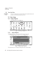
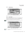
The Keyboard . . . . . . . . . . . . . . . . . . .
.
.
.
.
.
.
.
.
.
.
.
.
.
.
.
.
.
.
.
.
.
.
.
.
.
.
.
.
.
.
.
.
Psion Teklogix 8525 Vehicle-Mount Computer User Manual
1
Contents
3.4.1 Modifier Keys. . . . . . . . . . . . . . . . . . . . . .
3.4.2 The Keys . . . . . . . . . . . . . . . . . . . . . . . .
3.4.3 The Keypad Backlight . . . . . . . . . . . . . . . . .
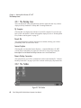
3.5 The Display . . . . . . . . . . . . . . . . . . . . . . . . . .
3.5.1 Calibrating The Touchscreen . . . . . . . . . . . . . .
3.6 8525 Indicators. . . . . . . . . . . . . . . . . . . . . . . . .
3.6.1 LEDs . . . . . . . . . . . . . . . . . . . . . . . . . .
3.6.2 Onscreen Indicators . . . . . . . . . . . . . . . . . . .
3.6.3 Audio Indicators . . . . . . . . . . . . . . . . . . . .
3.7 Scanning . . . . . . . . . . . . . . . . . . . . . . . . . . . .
3.7.1 Scanning Techniques . . . . . . . . . . . . . . . . . .
3.7.2 Scan LED Indicators . . . . . . . . . . . . . . . . . .
3.7.3 Troubleshooting. . . . . . . . . . . . . . . . . . . . .
3.7.4 Operating One Dimensional (1D) Laser Scanners . . .
3.8 Connecting & Disconnecting Tethered Peripherals . . . . . .
3.9 Monitoring The Network Connection . . . . . . . . . . . . .
3.10 Connecting An 8525 To A PC . . . . . . . . . . . . . . . . .
3.10.1 Using Microsoft® ActiveSync® To Work With Files .
3.11 General Maintenance . . . . . . . . . . . . . . . . . . . . .
3.11.1 Caring For The Touchscreen . . . . . . . . . . . . . .
3.11.2 Cleaning The 8525 . . . . . . . . . . . . . . . . . . .
.
.
.
.
.
.
.
.
.
.
.
.
.
.
.
.
.
.
.
.
.
.
.
.
.
.
.
.
.
.
.
.
.
.
.
.
.
.
.
.
.
.
.
.
.
.
.
.
.
.
.
.
.
.
.
.
.
.
.
.
.
.
.
.
.
.
.
.
.
.
.
.
.
.
.
.
.
.
.
.
.
.
.
.
.
.
.
.
.
.
.
.
.
.
.
.
.
.
.
.
.
.
.
.
.
29
30
32
32
32
33
33
35
37
37
37
37
38
38
39
39
40
41
41
41
42
.
.
.
.
.
.
.
.
.
.
.
.
.
.
.
.
.
.
.
.
.
.
.
.
.
.
.
.
.
.
.
.
.
.
.
.
.
.
.
.
.
.
.
.
.
.
.
.
.
.
.
.
.
.
.
.
.
.
.
.
.
.
.
.
.
45
45
46
47
47
48
48
50
50
51
53
55
56
Chapter 4: Working With Windows CE .NET
4.1
4.2
4.3
4.4
2
Navigating In Windows CE .NET And Applications
4.1.1 Navigating Using A Touchscreen And Stylus
4.1.2 Navigating Using The Keyboard . . . . . . .
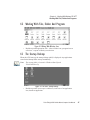
Working With Files, Folders And Programs . . . . .
The Startup Desktop . . . . . . . . . . . . . . . . .
4.3.1 The Desktop Icons . . . . . . . . . . . . . .
4.3.2 The Taskbar . . . . . . . . . . . . . . . . . .
The Start Menu. . . . . . . . . . . . . . . . . . . .
4.4.1 The Desktop. . . . . . . . . . . . . . . . . .
4.4.2 Security Levels . . . . . . . . . . . . . . . .
4.4.3 Programs . . . . . . . . . . . . . . . . . . .
4.4.4 Shortcuts . . . . . . . . . . . . . . . . . . .
4.4.5 Settings . . . . . . . . . . . . . . . . . . . .
Psion Teklogix 8525 Vehicle-Mount Computer User Manual
.
.
.
.
.
.
.
.
.
.
.
.
.
.
.
.
.
.
.
.
.
.
.
.
.
.
.
.
.
.
.
.
.
.
.
.
.
.
.
.
.
.
.
.
.
.
.
.
.
.
.
.
.
.
.
.
.
.
.
.
.
.
.
.
.
Contents
4.5
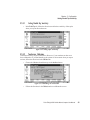
4.4.6 Run . . . . . . . . . . . . . . . . . . . . . . . . . . . . . . . . .57
4.4.7 Shutdown . . . . . . . . . . . . . . . . . . . . . . . . . . . . . .57
Using A Dialogue Box . . . . . . . . . . . . . . . . . . . . . . . . . .58
Chapter 5: Configuration
5.1
5.2
5.3
5.4
5.5
5.6
5.7
5.8
5.9
Remote Desktop Connection . . . . .
Pocket PC Compatibility . . . . . . .
The Control Panel . . . . . . . . . . .
Control Panel Icons . . . . . . . . . .
Basic Setup . . . . . . . . . . . . . .
5.5.1 Display Properties . . . . . . .
5.5.2 Keyboard Properties . . . . . .
5.5.3 Volume And Sound Properties.
5.5.4 Power Management Properties.
5.5.5 Stylus Properties . . . . . . . .
5.5.6 Certificate Assignment . . . . .
5.5.7 Narrow Band Radio . . . . . .
Bluetooth Setup . . . . . . . . . . . .
5.6.1 The Devices Tab . . . . . . . .
5.6.2 The Server Tab . . . . . . . . .
5.6.3 The Properties Tab . . . . . . .
5.6.4 The Bluetooth GPRS Phone . .
Total Recall . . . . . . . . . . . . . .
5.7.1 Creating A Backup Profile . . .
5.7.2 Restoring A Profile. . . . . . .
IPv6 Support. . . . . . . . . . . . . .
Scanner Properties Setup . . . . . . .
5.9.1 Scanner Options . . . . . . . .
5.9.2 Bar Codes . . . . . . . . . . .
5.9.3 Translations . . . . . . . . . .
.
.
.
.
.
.
.
.
.
.
.
.
.
.
.
.
.
.
.
.
.
.
.
.
.
.
.
.
.
.
.
.
.
.
.
.
.
.
.
.
.
.
.
.
.
.
.
.
.
.
.
.
.
.
.
.
.
.
.
.
.
.
.
.
.
.
.
.
.
.
.
.
.
.
.
.
.
.
.
.
.
.
.
.
.
.
.
.
.
.
.
.
.
.
.
.
.
.
.
.
.
.
.
.
.
.
.
.
.
.
.
.
.
.
.
.
.
.
.
.
.
.
.
.
.
.
.
.
.
.
.
.
.
.
.
.
.
.
.
.
.
.
.
.
.
.
.
.
.
.
.
.
.
.
.
.
.
.
.
.
.
.
.
.
.
.
.
.
.
.
.
.
.
.
.
.
.
.
.
.
.
.
.
.
.
.
.
.
.
.
.
.
.
.
.
.
.
.
.
.
.
.
.
.
.
.
.
.
.
.
.
.
.
.
.
.
.
.
.
.
.
.
.
.
.
.
.
.
.
.
.
.
.
.
.
.
.
.
.
.
.
.
.
.
.
.
.
.
.
.
.
.
.
.
.
.
.
.
.
.
.
.
.
.
.
.
.
.
.
.
.
.
.
.
.
.
.
.
.
.
.
.
.
.
.
.
.
.
.
.
.
.
.
.
.
.
.
.
.
.
.
.
.
.
.
.
.
.
.
.
.
.
.
.
.
.
.
.
.
.
.
.
.
.
.
.
.
.
.
.
.
.
.
.
.
.
.
.
.
.
.
.
.
.
.
.
.
.
.
.
.
.
.
.
.
.
.
.
.
.
.
.
.
.
.
.
.
.
.
.
.
.
.
.
.
.
.
.
.
.
.
.
.
.
.
.
.
.
.
.
.
.
.
.
.
.
.
.
.
.
.
.
.
.
.
.
.
.
.
.
.
.
.
.
.
.
.
.
.
.
.
.
.
.
.
.63
.63
.63
.64
.68
.68
.70
.79
.80
.82
.84
.85
.97
.98
101
101
103
108
108
111
112
113
113
116
126
.
.
.
.
.
.
.
.
.
.
.
.
.
.
.
.
.
.
.
.
.
.
.
.
.
.
.
.
.
.
.
.
.
.
.
.
.
.
.
.
.
.
.
.
.
.
.
.
.
.
.
.
.
.
.
.
.
.
.
.
.
.
.
.
.
.
.
.
133
133
133
134
Chapter 6: Tekterm Application
6.1
6.2
The Tekterm Application . . . . . .
Additional Keyboard Functions . . .
6.2.1 Function Keys And Softkeys.
6.2.2 Macro Keys. . . . . . . . . .
.
.
.
.
Psion Teklogix 8525 Vehicle-Mount Computer User Manual
3
Contents
6.3
6.4
6.5
6.6
6.7
6.8
6.9
6.10
6.11
6.12
6.13
6.14
4
Changing The Screen Font Size . . . . . . . . . . . . . . . . .
Panning The Screen Contents . . . . . . . . . . . . . . . . . .
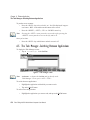
The Task Manager–Switching Between Applications . . . . . .
The Tekterm Status Area. . . . . . . . . . . . . . . . . . . . .
TESS Emulation . . . . . . . . . . . . . . . . . . . . . . . . .
6.7.1 Configuration . . . . . . . . . . . . . . . . . . . . . . .
6.7.2 Working With Multiple Sessions . . . . . . . . . . . . .
6.7.3 The Field Types. . . . . . . . . . . . . . . . . . . . . .
6.7.4 IBM 5250 Emulation Keys . . . . . . . . . . . . . . . .
6.7.5 Data Entry. . . . . . . . . . . . . . . . . . . . . . . . .
6.7.6 TESS Status Message . . . . . . . . . . . . . . . . . . .
6.7.7 Lock Messages . . . . . . . . . . . . . . . . . . . . . .
6.7.8 Control Commands . . . . . . . . . . . . . . . . . . . .
6.7.9 Resetting A TESS Session . . . . . . . . . . . . . . . .
6.7.10 The Local Menu . . . . . . . . . . . . . . . . . . . . .
6.7.11 Selecting Another Host Computer . . . . . . . . . . . .
6.7.12 Queuing Mode . . . . . . . . . . . . . . . . . . . . . .
ANSI Emulation . . . . . . . . . . . . . . . . . . . . . . . . .
6.8.1 Configuration . . . . . . . . . . . . . . . . . . . . . . .
6.8.2 Sending Data To The Host . . . . . . . . . . . . . . . .
6.8.3 Psion Teklogix Keyboard And VT220 Equivalent Keys .
6.8.4 Block Mode (Local Editing) . . . . . . . . . . . . . . .
6.8.5 Working With Sessions . . . . . . . . . . . . . . . . . .
The Radio Statistics Screen . . . . . . . . . . . . . . . . . . .
6.9.1 802.IQ Stats Screen . . . . . . . . . . . . . . . . . . . .
6.9.2 Exiting The Radio Statistics Screen . . . . . . . . . . .
The Tekterm Startup Display Menu . . . . . . . . . . . . . . .
Working With Menus . . . . . . . . . . . . . . . . . . . . . .
6.11.1 Using The Touchscreen To Navigate Through Menus . .
6.11.2 Using The Keyboard To Navigate Through Menus . . .
6.11.3 Saving Changes To Parameters. . . . . . . . . . . . . .
6.11.4 Retrieving Default Parameter Values. . . . . . . . . . .
Resetting The 8525 Vehicle-Mount Computer . . . . . . . . .
The Parameters Menu . . . . . . . . . . . . . . . . . . . . . .
6.13.1 Security Settings . . . . . . . . . . . . . . . . . . . . .
Display Options . . . . . . . . . . . . . . . . . . . . . . . . .
Psion Teklogix 8525 Vehicle-Mount Computer User Manual
.
.
.
.
.
.
.
.
.
.
.
.
.
.
.
.
.
.
.
.
.
.
.
.
.
.
.
.
.
.
.
.
.
.
.
.
.
.
.
.
.
.
.
.
.
.
.
.
.
.
.
.
.
.
.
.
.
.
.
.
.
.
.
.
.
.
.
.
.
.
.
.
.
.
.
.
.
.
.
.
.
.
.
.
.
.
.
.
.
.
.
.
.
.
.
.
.
.
.
.
.
.
.
.
.
.
.
.
.135
.135
.136
.137
.137
.138
.138
.138
.139
.139
.143
.144
.144
.144
.145
.145
.146
.146
.146
.147
.147
.148
.149
.150
.151
.152
.153
.153
.154
.155
.158
.159
.159
.159
.160
.160
Contents
6.15 More Parameters . . . . . . . . . . . . . . . . . . . . . .
6.16 Radio Parameters . . . . . . . . . . . . . . . . . . . . . .
6.17 System Parameters . . . . . . . . . . . . . . . . . . . . .
6.17.1 Keyboard . . . . . . . . . . . . . . . . . . . . . . .
6.17.2 Audio . . . . . . . . . . . . . . . . . . . . . . . . .
6.17.3 Power Mgmt Ctrl Panel . . . . . . . . . . . . . . .
6.17.4 User Permissions . . . . . . . . . . . . . . . . . . .
6.17.5 Auto Start. . . . . . . . . . . . . . . . . . . . . . .
6.18 Scanner Control Panel. . . . . . . . . . . . . . . . . . . .
6.19 View Manager . . . . . . . . . . . . . . . . . . . . . . . .
6.19.1 Split Screen. . . . . . . . . . . . . . . . . . . . . .
6.19.2 Custom Characters (Unicode™) . . . . . . . . . . .
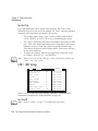
6.20 Applications . . . . . . . . . . . . . . . . . . . . . . . . .
6.20.1 ANSI Settings . . . . . . . . . . . . . . . . . . . .
6.20.2 TESS Settings . . . . . . . . . . . . . . . . . . . .
6.21 Ports– Tether And Console . . . . . . . . . . . . . . . . .
6.21.1 Tether And Console Port Peripheral Options . . . .
6.21.2 Tether, Serial And Console Port Parameter Settings.
6.21.3 Tether And Console Port Scan-See Parameters . . .
6.22 Network . . . . . . . . . . . . . . . . . . . . . . . . . . .
6.22.1 Network Ctrl Panel Settings . . . . . . . . . . . . .
6.22.2 802.IQ v2 . . . . . . . . . . . . . . . . . . . . . . .
.
.
.
.
.
.
.
.
.
.
.
.
.
.
.
.
.
.
.
.
.
.
.
.
.
.
.
.
.
.
.
.
.
.
.
.
.
.
.
.
.
.
.
.
.
.
.
.
.
.
.
.
.
.
.
.
.
.
.
.
.
.
.
.
.
.
.
.
.
.
.
.
.
.
.
.
.
.
.
.
.
.
.
.
.
.
.
.
.
.
.
.
.
.
.
.
.
.
.
.
.
.
.
.
.
.
.
.
.
.
.
.
.
.
.
.
.
.
.
.
.
.
.
.
.
.
.
.
.
.
.
.
161
161
163
164
165
167
167
168
168
169
170
172
175
176
194
217
217
218
221
226
226
227
External Bar Code Readers . . . . . . . . . . . . . . . . . . . .
7.1.1 PowerScan™ Standard, LR and XLR Bar Code Scanners
7.1.2 Entering Data With The Bar Code Reader. . . . . . . . .
Bluetooth Peripherals . . . . . . . . . . . . . . . . . . . . . . .
GPS Unit . . . . . . . . . . . . . . . . . . . . . . . . . . . . .
Mounting Accessories . . . . . . . . . . . . . . . . . . . . . . .
7.4.1 8525 Mounting Recommendations . . . . . . . . . . . .
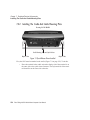
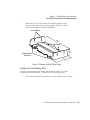
7.4.2 Installing The Cradle And Cradle Mounting Plate. . . . .
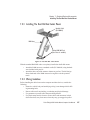
7.4.3 Installing The Dual Ball And Socket Mount. . . . . . . .
7.4.4 Wiring Guidelines . . . . . . . . . . . . . . . . . . . . .
7.4.5 8525 Installation in High Voltage Vehicles: . . . . . . . .
7.4.6 8525 Installation In Vehicles. . . . . . . . . . . . . . . .
.
.
.
.
.
.
.
.
.
.
.
.
.
.
.
.
.
.
.
.
.
.
.
.
.
.
.
.
.
.
.
.
.
.
.
.
231
231
231
231
232
232
233
234
237
237
238
239
Chapter 7: Peripheral Devices & Accessories
7.1
7.2
7.3
7.4
Psion Teklogix 8525 Vehicle-Mount Computer User Manual
5
Contents
7.4.7 Wiring Vehicle Power To The 8525 . . . . . . . . . . . . . . .239
Chapter 8: Specifications
8.1
8.2
8.3
8.4
8.5
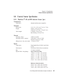
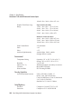
8525 Vehicle-Mount Computer Specifications . . . . . . .
Radio Specifications . . . . . . . . . . . . . . . . . . . . .
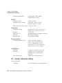
Bar Code Scanning. . . . . . . . . . . . . . . . . . . . . .
8.3.1 External Scanners . . . . . . . . . . . . . . . . . . .
External Scanner Specifications . . . . . . . . . . . . . . .
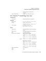
8.4.1 PowerScan™ LR and XLR Industrial Scanner Specs
8.4.2 PowerScan™ Standard Range Scanner Specs . . . .
Internal Lithium-Ion Battery. . . . . . . . . . . . . . . . .
.
.
.
.
.
.
.
.
.
.
.
.
.
.
.
.
.
.
.
.
.
.
.
.
.
.
.
.
.
.
.
.
.
.
.
.
.
.
.
.
.243
.245
.246
.246
.246
.246
.248
.250
Appendix A: Support Services And Worldwide Offices
A.1 Technical Support . . . . . . . . . . . . . . . . . . . . . . . . . . . .A-1
A.2 Product Repairs . . . . . . . . . . . . . . . . . . . . . . . . . . . . .A-1
A.3 Worldwide Offices . . . . . . . . . . . . . . . . . . . . . . . . . . . .A-2
Appendix B: Port Pinouts
B.1 Tether Port Pinout . . . . . . . . . . . . . . . . . . . . . . . . . . . .B-1
B.2 RS232 Port Pinout . . . . . . . . . . . . . . . . . . . . . . . . . . . .B-1
B.3 DB-26 Auxiliary Port Pinout. . . . . . . . . . . . . . . . . . . . . . .B-2
Appendix C: USB Setup Application
C.1 USB Setup . . . . . . . . . . . . . . . . . . . . . . . . . . . . .
C.1.1 Launching The Application . . . . . . . . . . . . . . . .
C.1.2 Pre-Installation: Updating usbstor.inf And wceusbsh.inf .
C.1.3 Installation: Installing The 8525 As a Device On Your PC
C.1.4 Post Installation . . . . . . . . . . . . . . . . . . . . . .
6
Psion Teklogix 8525 Vehicle-Mount Computer User Manual
.
.
.
.
.
.
.
.
.
.
.C-1
.C-1
.C-2
.C-4
.C-5
PROGRAM LICENSE AGREEMENTS
Microsoft's End User License Agreement
You have acquired a device (“DEVICE”) that includes software licensed by Psion
Teklogix Inc. from Microsoft Licensing Inc. or its affiliates (‘MS”). Those installed
software products of MS origin, as well as associated media, printed materials, and
“online” or electronic documentation (“SOFTWARE”) are protected by international intellectual property laws and treaties. The SOFTWARE is licensed, not sold.
All rights reserved.
IF YOU DO NOT AGREE TO THIS END USER LICENSE AGREEMENT
(“EULA”), DO NOT USE THE DEVICE OR COPY THE SOFTWARE.
INSTEAD, PROMPTLY CONTACT PSION TEKLOGIX INC. FOR INSTRUCTIONS ON RETURN OF THE UNUSED DEVICE(S) FOR A REFUND. ANY
USE OF THE SOFTWARE, INCLUDING BUT NOT LIMITED TO USE ON
THE DEVICE, WILL CONSTITUTE YOUR AGREEMENT TO THIS EULA
(OR RATIFICATION OF ANY PREVIOUS CONSENT).
GRANT OF SOFTWARE LICENSE. This EULA grants you the following
license:
•
You may use the SOFTWARE only on the DEVICE.
•
NOT FAULT TOLERANT. THE SOFTWARE IS NOT FAULT TOLERANT. PSION TEKLOGIX INC. HAS INDEPENDENTLY DETERMINED HOW TO USE THE SOFTWARE IN THE DEVICE, AND MS
HAS RELIED UPON PSION TEKLOGIX INC. TO CONDUCT SUFFICIENT TESTING TO DETERMINE THAT THE SOFTWARE IS SUITABLE FOR SUCH USE.
•
NO WARRANTIES FOR THE SOFTWARE. THE SOFTWARE is provided “AS IS” and with all faults. THE ENTIRE RISK AS TO SATISFACTORY QUALITY, PERFORMANCE, ACCURACY, AND
EFFORT (INCLUDING LACK OF NEGLIGENCE) IS WITH YOU.
ALSO, THERE IS NO WARRANTY AGAINST INTERFERENCE
WITH YOUR ENJOYMENT OF THE SOFTWARE OR AGAINST
Psion Teklogix 8525 Vehicle-Mount Computer User Manual
I
License Agreement
INFRINGEMENT. IF YOU HAVE RECEIVED ANY WARRANTIES
REGARDING THE DEVICE OR THE SOFTWARE, THOSE WARRANTIES DO NOT ORIGINATE FROM, AND ARE NOT BINDING ON, MS.
II
•
Note on Java Support. The SOFTWARE may contain support for programs written in Java. Java technology is not fault tolerant and is not
designed, manufactured, or intended for use or resale as online control
equipment in hazardous environments requiring fail-safe performance, such
as in the operation of nuclear facilities, aircraft navigation or communication systems, air traffic control, direct life support machines, or weapons
systems, in which the failure of Java technology could lead directly to
death, personal injury, or severe physical or environmental damage. Sun
Microsystems, Inc. has contractually obligated MS to make this disclaimer.
•
No Liability for Certain Damages. EXCEPT AS PROHIBITED BY
LAW, MS SHALL HAVE NO LIABILITY FOR ANY INDIRECT,
SPECIAL, CONSEQUENTIAL OR INCIDENTAL DAMAGES
ARISING FROM OR IN CONNECTION WITH THE USE OR PERFORMANCE OF THE SOFTWARE. THIS LIMITATION SHALL
APPLY EVEN IF ANY REMEDY FAILS OF ITS ESSENTIAL PURPOSE. IN NO EVENT SHALL MS BE LIABLE FOR ANY AMOUNT
IN EXCESS OF U.S. TWO HUNDRED FIFTY DOLLARS
(U.S.$250.OO).
•
Limitations on Reverse Engineering, Decompilation, and Disassembly.
You may not reverse engineer, decompile, or disassemble the SOFTWARE,
except and only to the extent that such activity is expressly permitted by
applicable law notwithstanding this limitation.
•
SOFTWARE TRANSFER ALLOWED BUT WITH RESTRICTIONS.
You may permanently transfer rights under this EULA only as part of a permanent sale or transfer of the Device, and only if the recipient agrees to this
EULA. If the SOFTWARE is an upgrade, any transfer must also include all
prior versions of the SOFTWARE.
•
EXPORT RESTRICTIONS. You acknowledge that SOFTWARE is
subject to U.S. export jurisdiction. You agree to comply with all applicable
international and national laws that apply to the SOFTWARE, including the
U.S. Export Administration Regulations, as well as end-user, end-use and
destination restrictions issued by U.S. and other governments. For additional information see http://www.microsoft.com/exporting/.
Psion Teklogix 8525 Vehicle-Mount Computer User Manual
License Agreement
Meetinghouse Data Communications, Inc. End User License Agreement
End User License Agreement:
ATTENTION: PLEASE READ THIS SOFTWARE LICENSE AGREEMENT
("LICENSE") CAREFULLY BEFORE INSTALLATION. USE OF THE SOFTWARE IS SUBJECT TO THE SOFTWARE LICENSE TERMS SET FORTH
BELOW. USING THE SOFTWARE INDICATES YOUR ACCEPTANCE OF
THESE LICENSE TERMS. IF YOU DO NOT ACCEPT THESE LICENSE
TERMS, YOU MUST RETURN THE SOFTWARE FOR A FULL REFUND. IF
THE SOFTWARE IS SUPPLIED WITH ANOTHER PRODUCT, YOU MAY
RETURN THE ENTIRE UNUSED PRODUCT FOR A FULL REFUND.
Software License Terms:
The following terms govern your use of the enclosed Software unless you have a
separate written agreement with Meetinghouse Data Communications, Inc. herein
also known as “MDC”.
License Grant:
MDC grants you a non-exclusive and non-transferable license to Use one copy of
the Software. "Use" means storing, loading, installing, executing or displaying the
Software. “Software” means software, documentation and any fonts accompanying
this License whether on disk, in read only memory, on any other media or in any
other form. You may not modify the Software or disable any licensing or control
features of the Software. If the Software is licensed for "concurrent use", you may
not allow more than the maximum number of authorized users to Use the Software
concurrently.
The Software is licensed as a "Shareware" version, on one computer only. You may
use the Software distributed and licensed as Shareware on a trial basis only. The
shareware version of the Software may be distributed freely without any associated
fees to other parties who wish to try the software as long as the Software is distributed within an exact copy of the original MDC self-extracting installation file. In
other words, nothing may be left out of the Shareware as distributed on MDC's web
site at http://www.mtghouse.com.
Psion Teklogix 8525 Vehicle-Mount Computer User Manual
III
License Agreement
All permanent licenses are prepaid and the Software is licensed to you by MDC.
You own the media on which the Software is recorded but MDC and/or MDC’s
licensor(s) retain title to the Software. The Software and any copies which this
License authorizes you to make are subject to this License.
Permitted Uses and Restrictions:
This License allows you to install and use the Software on a single computer at a
time. This License does not allow the Software to exist on more than one computer
at a time. You may make one copy of the Software in machine-readable form for
backup purposes only. The backup copy must include all copyright information contained on the original. Except as expressly permitted in this License, you may not, in
whole or part, decompile, reverse engineer, disassemble, modify, rent, lease, loan,
sublicense, distribute or create derivative works based upon the Software, or transmit the Software over a network. You may not copy the Software onto any bulletin
board or similar system. You agree that you will not utilize any information obtained
from MDC or obtained or learned in the course of using the Software, to develop or
improve technology with similar functionality to the Software, nor will you directly
or indirectly assist any other party in doing so. You further agree that you will not
separate the various modules of the software for their different purposes, if any.
High Risk Activities:
The Software is not fault-tolerant and is not designed, manufactured or intended for
use or resale as on-line control equipment in hazardous environments requiring failsafe performance, such as in the operation of nuclear facilities, aircraft navigation or
communication systems, air traffic control, direct life support machines, or weapons
systems, in which the failure of the Software could lead directly to death, personal
injury, or severe physical or environmental damage ("High Risk Activities").
Accordingly, MDC and its suppliers specifically disclaim any express or implied
warranty of fitness for High Risk Activities. You agree that MDC and its suppliers
will not be liable for any claims or damages arising from the use of the Software in
such applications.
Ownership:
The Software is licensed, not sold. The Software is owned and copyrighted by MDC
or its third party suppliers. Your license confers no title or ownership in the Software
and is not a sale of any rights in the Software. You acknowledge such ownership and
intellectual property rights and will not take any action to jeopardize, limit or interfere in any manner with MDC's or its suppliers' ownership of or rights with respect
IV
Psion Teklogix 8525 Vehicle-Mount Computer User Manual
License Agreement
to the Software. The Software is protected by copyright and other intellectual property laws and by international treaties. MDC's third party suppliers may protect their
rights in the event of any violation of these License Terms.
Termination:
Your rights under this License will terminate automatically without notice from
MDC if you fail to comply with any term(s) of this License. Upon termination, you
must immediately destroy the Software, together with all copies, adaptations and
merged portions in any form.
U.S. Government Restricted Rights:
The Software and documentation have been developed entirely at private expense
and are provided as "Commercial Computer Software" or "restricted computer software". They are delivered and licensed as "commercial computer software" as
defined in DFARS 252.227-7013 (Oct 1988), DFARS 252.211-7015 (May 1991) or
DFARS 252.227-7014 (Jun 1995), as a "commercial item" as defined in FAR 2.101
(a), or as "Restricted computer software" as defined in FAR 52.227-19 (Jun 1987)
(or any equivalent agency regulation or contract clause), whichever is applicable.
You have only those rights provided for such Software and Documentation by the
applicable FAR or DFARS clause or the MDC standard software agreement for the
product.
Export Law Assurances:
You may not use or otherwise export or reexport the Software except as authorized
by United States law and the laws of the jurisdiction in which the Software was
obtained. In particular, but without limitation, the Software may not be exported or
reexported (i) into (or to a national or resident of) any U.S. embargoed country or
(ii) to anyone on the U.S. Treasury Department's list of Specially Designated
Nationals or the U.S. Department of Commerce's Table of Denial Orders. By using
the Software, you represent and warrant that you are not located in, under control of,
or a national or resident of any such country or on any such list.
Limited Warranty on Media: (if applicable)
MDC warrants the media on which the Software is recorded to be free from defects
in materials and workmanship under normal use for a period of ninety (90) days
from the date of original retail purchase. Your exclusive remedy under this paragraph shall be, at MDC's option, a refund of the purchase price of the product containing the Software or replacement of the Software which is returned to MDC or a
Psion Teklogix 8525 Vehicle-Mount Computer User Manual
V
License Agreement
MDC authorized representative with a copy of the receipt. THIS LIMITED WARRANTY AND ANY IMPLIED WARRANTIES ON THE MEDIA INCLUDING
THE IMPLIED WARRANTIES OF MERCHANTABILITY AND FITNESS FOR
A PARTICULAR PURPOSE ARE LIMITED IN DURATION TO NINETY (90)
DAYS FROM THE DATE OF ORIGINAL RETAIL PURCHASE. SOME JURISDICTIONS DO NOT ALLOW LIMITATIONS ON HOW LONG AN IMPLIED
WARRANTY LASTS, SO THIS LIMITATION MAY NOT APPLY TO YOU. THE
LIMITED WARRANTY SET FORTH HEREIN IS EXCLUSIVE AND IN LIEU
OF ALL OTHERS, WHETHER ORAL OR WRITTEN, EXPRESS OR IMPLIED.
LICENSOR SPECIFICALLY DISCLAIMS ALL OTHER WARRANTIES. THIS
LIMITED WARRANTY GIVES YOU SPECIFIC LEGAL RIGHTS, AND YOU
MAY ALSO HAVE OTHER RIGHTS WHICH VARY BY JURISDICTION.
Disclaimer of Warranty on Software:
You expressly acknowledge and agree that use of the Software is at your sole risk.
The Software is provided "AS IS" and without warranty of any kind and MDC and
MDC’s licensor(s) (for the purposes of warranty and liability, MDC and MDC's
licensor(s) shall be collectively referred to as "MDC") EXPRESSLY DISCLAIM
ALL WARRANTIES AND/OR CONDITIONS, EXPRESS OR IMPLIED,
INCLUDING, BUT NOT LIMITED TO, THE IMPLIED WARRANTIES
AND/OR CONDITIONS OF MERCHANTABILITY OR SATISFACTORY
QUALITY AND FITNESS FOR A PARTICULAR PURPOSE AND NONINFRINGEMENT OF THIRD PARTY RIGHTS. LICENSOR DOES NOT WARRANT THAT THE FUNCTIONS CONTAINED IN THE SOFTWARE WILL
MEET YOUR REQUIREMENTS, OR THAT THE OPERATION OF THE SOFTWARE WILL BE UNINTERRUPTED OR ERROR-FREE, OR THAT DEFECTS
IN THE SOFTWARE WILL BE CORRECTED. FURTHERMORE, LICENSOR
DOES NOT WARRANT OR MAKE ANY REPRESENTATIONS REGARDING
THE USE OR THE RESULTS OF THE USE OF THE SOFTWARE OR
RELATED DOCUMENTATION IN TERMS OF THEIR CORRECTNESS,
ACCURACY, RELIABILITY, OR OTHERWISE. NO ORAL OR WRITTEN
INFORMATION OR ADVICE GIVEN BY LICENSOR OR AN LICENSOR
AUTHORIZED REPRESENTATIVE SHALL CREATE A WARRANTY OR IN
ANY WAY INCREASE THE SCOPE OF THIS WARRANTY. SHOULD THE
SOFTWARE PROVE DEFECTIVE, YOU (AND NOT LICENSOR OR AN
LICENSOR AUTHORIZED REPRESENTATIVE) ASSUME THE ENTIRE
COST OF ALL NECESSARY SERVICING, REPAIR OR CORRECTION. SOME
JURISDICTIONS DO NOT ALLOW THE EXCLUSION OF IMPLIED WAR-
VI
Psion Teklogix 8525 Vehicle-Mount Computer User Manual
License Agreement
RANTIES, SO THE ABOVE EXCLUSION MAY NOT APPLY TO YOU. THE
TERMS OF THIS DISCLAIMER DO NOT AFFECT OR PREJUDICE THE
STATUTORY RIGHTS OF A CONSUMER ACQUIRING LICENSOR PRODUCTS OTHERWISE THAN IN THE COURSE OF A BUSINESS, NEITHER DO
THEY LIMIT OR EXCLUDE ANY LIABILITY FOR DEATH OR PERSONAL
INJURY CAUSED BY LICENSOR’S NEGLIGENCE.
Limitation of Liability:
UNDER NO CIRCUMSTANCES, EXCEPT TO THE EXTENT PROHIBITED
BY LOCAL LAW, INCLUDING NEGLIGENCE, SHALL LICENSOR, ITS SUBSIDIARIES, AFFILIATES, OR SUPPLIERS BE LIABLE FOR ANY DIRECT,
INCIDENTAL, SPECIAL, INDIRECT OR CONSEQUENTIAL DAMAGES
(INCLUDING LOST PROFIT, LOST DATA, OR DOWNTIME COSTS) ARISING OUT OF OR RELATING TO THIS LICENSE, THE USE, INABILITY TO
USE, OR THE RESULTS OF USE OF THE SOFTWARE, WHETHER BASED IN
WARRANTY, CONTRACT, TORT OR OTHER LEGAL THEORY, AND
WHETHER OR NOT ADVISED OF THE POSSIBILITY OF SUCH DAMAGES.
In no event shall MDC's total liability to you for all damages exceed the price paid
for the license to use the Software, regardless of the form of the claim.
Government End Users:
If the Software is supplied to the United States Government, the Software is classified as "restricted computer software" as defined in clause 52.227-19 of the FAR.
The United States Government's rights to the Software are as provided in clause
52.227-19 of the FAR.
Controlling Law and Severability:
This License shall be governed by the laws of the United States and the State of
New Hampshire. As to any dispute relating to this License or the Software, you further agree to jurisdiction and venue in the Federal and State Courts located in the
State of New Hampshire. If for any reason a court of competent jurisdiction finds
any provision, or portion thereof, to be unenforceable, the remainder of this License
shall continue in full force and effect.
Acknowledgement:
Your use of any software produced by MDC is based only on your acknowledgement that you have read this License, understand it, and agree to be bound by its
terms and conditions.
Psion Teklogix 8525 Vehicle-Mount Computer User Manual
VII
License Agreement
MDC Acknowledgments:
This product includes software developed by MDC and its licensors. This product
includes software developed by the OpenSSL Project for use in the OpenSSL Toolkit (http://www.openssl.org/)". This product includes cryptographic software written
by Eric Young ([email protected]). This product includes software written by Tim
Hudson ([email protected]).
Complete Agreement:
This License constitutes the entire agreement between the parties with respect to the
use of the Software and supersedes all prior or contemporaneous understandings
regarding such subject matter. No amendment to or modification of this License will
be binding unless in writing and signed by MDC.
NOTE: EXCEPT TO THE EXTENT ALLOWED BY LOCAL LAW, THESE
WARRANTY TERMS DO NOT EXCLUDE, RESTRICT, OR MODIFY, AND
ARE IN ADDITION TO, THE MANDATORY STATUTORY RIGHTS APPLICABLE TO THE LICENSE OF THE SOFTWARE TO YOU.
Meetinghouse Data Communications, Inc.
150 Greenleaf Avenue, Unit F
Portsmouth, NH 03801
Revised 8/12/2002
VIII
Psion Teklogix 8525 Vehicle-Mount Computer User Manual
APPROVALS AND SAFETY SUMMARY
Declaration Of Conformity
Product:
Application of Council
Directive(s):
Conformity Declared
to Standards:
Manufacturer:
Year of Manufacture:
Manufacturer’s Address
in the European
Community:
Type of Equipment:
Equipment Class:
8525 Vehicle-Mount Computer
EMC Directive:
89/336/EEC
Low Voltage Directive: 73/23/EEC
EN 55022: 1998 + Am 1, Class B;
EN 61000-3-2; EN 61000-3-3
EN 55024:1998;
EN 61000-4-2; ±4kV CD; ±8kV AD
EN 61000-4-2; ±4kV CD; ±8kV AD
EN 61000-4-3; 3V/m, 80-1000 MHz
EN 61000-4-4; ±1kV Power lines
EN 61000-4-5; ±1kV Differential mode
EN 61000-4-6; 3VRMS, 150kHz-80MHz
EN 61000-4-11; AC Mains Ports
PSION TEKLOGIX INC.
2100 Meadowvale Boulevard
Mississauga, Ontario, Canada
L5N 7J9
2003
PSION TEKLOGIX S.A.
La Duranne; 135 Rue Rene Descartes; BP 421000
13591 Aix-En-Provence
Cedex 3; France
Information Technology Equipment
Commercial and Light Industrial
I the undersigned hereby declare that the equipment specified above conforms to
the above directives and standards.
Manufacturer:
Legal Representative
Rob Williams
Vice President of Engineering
Psion Teklogix Inc. Ontario
Domique Binckly
Vice President International Sales
Psion Teklogix S.A. France
Psion Teklogix 8525 Vehicle-Mount Computer User Manual
IX
Approvals And Safety Summary
This equipment complies with Class B Part 15 of the FCC rules.
Operation is subject to the following two conditions:
1. This device may not cause harmful interference, and
2. This device must accept any interference received, including interference that may cause undesired operation.
Changes or modifications not expressly approved by Psion Teklogix, the party
responsible for compliance, may void the user's authority to operate the equipment.
1. FCC Information to Users
For Class B Unintentional Radiators:
This equipment has been tested and found to comply with the limits for a Class B
digital device, pursuant to Part 15 of the FCC Rules. These limits are designed to
provide reasonable protection against harmful interference in a residential installation. This equipment generates, uses, and can radiate radio frequency energy
and, if not installed and used in accordance with the instruction manual, may
cause harmful interference to radio communications. However, there is no guarantee that interference will not occur in a particular installation. If this equipment
does cause harmful interference to radio or television reception, which can be
determined by turning the equipment off and on, the user is encouraged to try to
correct the interference by one of more of the following measures:
•
Reorient or relocate the receiving antenna
•
Increase the separation between the equipment and receiver
•
Connect the equipment into an outlet on a circuit different from that to
which the receiver is connected.
•
Consult the dealer or an experienced radio/TV technician for help.
2. Warning to Users
Warning:
X
Changes or modifications not expressly approved by Psion
Teklogix Inc. could void the user's authority to operate the
equipment.
Psion Teklogix 8525 Vehicle-Mount Computer User Manual
Approvals And Safety Summary
RF EXPOSURE
Warning:
To satisfy FCC RF exposure requirements for vehicle mount
transmitting devices, a separation distance of 20 cms should be
maintained between the antenna of this device and persons
during device operation. To ensure compliance, operations at
closer than this distance is not recommended.
DO NOT REMOVE COVERS OR OPEN ENCLOSURES
To avoid injury, the equipment covers and enclosures should only be
removed by qualified service personnel. Do not operate the equipment
without the covers and enclosures properly installed.
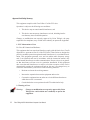
CAUTION
Use of the Vehicle Mount Computer while charging the fork truck battery is
prohibited.
CAUTION
Use of additional wiring and attachments not recommended or sold by the
manufacturer may result in fire, electric shock or personal injury.
CAUTION
If using an AC adaptor, use only the AC adaptor recommended by
manufacturer.
CAUTION
Do not operate the vehicle-mount computer with a damaged cord or plug.
Replace immediately.
CAUTION
Make sure the cord is positioned so that it is not stepped on, tripped over or
otherwise subjected to damage or stress.
Psion Teklogix 8525 Vehicle-Mount Computer User Manual
XI
Approvals And Safety Summary
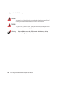
CAUTION
An extension cord should not be used unless absolutely necessary. Use of
an improper extension cord could result in fire or electric shock.
CAUTION
To reduce risk of electric shock, unplug the vehicle-mount computer from
the DC source before attempting any maintenance or cleaning.
Warning:
XII
Physically disconnect the 8525 from the vehicle battery during
battery charging (into AC outlet).
Psion Teklogix 8525 Vehicle-Mount Computer User Manual
1
INTRODUCTION
1.1 About This Manual . . . . . . . . . . . . . . . . . . . . . . . . . . . . . . 3
1.2 Text Conventions . . . . . . . . . . . . . . . . . . . . . . . . . . . . . . . 4
1.3 About The 8525 Vehicle-Mount Computer
1.3.1 Features . . . . . . . . . . . . . . .
1.3.2 The 8525 Vehicle-Mount Computer .
1.3.4 Regulatory Labels . . . . . . . . . .
.
.
.
.
.
.
.
.
.
.
.
.
.
.
.
.
.
.
.
.
.
.
.
.
.
.
.
.
.
.
.
.
.
.
.
.
.
.
.
.
.
.
.
.
. . . . . . .5
. . . . . . . 5
. . . . . . . 8
. . . . . . . 9
Psion Teklogix 8525 Vehicle-Mount Computer User Manual
1
Chapter 1: Introduction
About This Manual
1.1 About This Manual
This manual describes how to configure, operate and maintain the Psion Teklogix
8525 vehicle-mount computer.
Chapter 1: Introduction
provides a basic overview of the 8525 vehicle-mount.
Chapter 2: Basic Checkout
describes the steps required to get the 8525 ready for operation.
Chapter 3: Getting To Know Your 8525
describes the 8525 features and provides a description of the keyboard, how to
navigate in Microsoft® Windows® CE, and so on.
Chapter 4: Working With Windows CE .NET
describes the Microsoft® Windows® CE desktop and how to use it. This
chapter also outlines the basics of moving around a Windows CE .NET window,
selecting and opening icons, files, folders and working with a Windows
dialogue box.
Chapter 5: Configuration
provides a description of the Windows CE .NET Control Panel and how to use it
to configure the 8525, along with the scanners attached to the unit, and so on.
Chapter 6: Tekterm Application
describes TESS and ANSI operations. This chapter also provides descriptions of
the Tekterm parameters.
Chapter 7: Peripheral Devices & Accessories
describes the peripherals and accessories available for your 8525.
Chapter 8: Specifications
details radio, vehicle-mount computer and battery specifications.
Appendix A: Support Services And Worldwide Offices
provides the helpdesk phone number at the Mississauga, Ontario, Canada office
and details the support services available. This appendix also lists the worldwide office addresses and phone numbers.
Appendix B: Port Pinouts
includes 8525 pinouts.
Appendix C: USB Setup Application
describes the USB application.
Psion Teklogix 8525 Vehicle-Mount Computer User Manual
3
Chapter 1: Introduction
Text Conventions
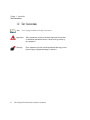
1.2 Text Conventions
Note: Notes highlight additional helpful information.
4
Important:
These statements provide particularly important instructions
or additional information that is critical to the operation of
the equipment.
Warning:
These statements provide critical information that may prevent
physical injury, equipment damage or data loss.
Psion Teklogix 8525 Vehicle-Mount Computer User Manual
Chapter 1: Introduction
About The 8525 Vehicle-Mount Computer
1.3 About The 8525 Vehicle-Mount Computer
The 8525 is a ruggedized vehicle-mount computer, running the Microsoft®
Windows CE .NET operating system. It is intended for use in commercial and light
industrial applications with a focus on real time wireless data transactions. All
possible bar code input methodologies are supported by a variety of scanners
available.
1.3.1 Features
•
Processor And Memory:
- 400MHz ARM RISC (400 MIPS).
- 32KB instruction/32KB data cache
- on-board RAM: 128mByte SDRAM
- on-board ROM: 64 MByte FLASH.
•
Operating System
- Windows CE .NET 4.2
•
Wireless Communication:.
- IEEE 802.11b 11 Mbps 2.4 GHz Compact Flash radio external and
internal antenna
- IEEE 802.11b 11 Mbps 2.4 GHz external antenna PC Card Slot radio
- standard antenna integrated onto radio card
- Future radio additions:
- IEEE 802.11g 22Mbps 2.4GHz Compact Flash radio
- IEEE 802.11a 54Mbps 5 GHz Compact Flash radio
- IEEE 802.11a 54Mbps 5 GHz PC Card radio
- NextGen Narrowband 400-500 MHz radio
- GSM/GPRS PC Card radio (for future release)
- Bluetooth SD I/O radio 2.4 GHz (5m range)
•
Application Software
- Internet Explorer 6 for CE
- Open Tekterm
- ANSI, TESS terminal emulations (IBM 3270, IBM 5250, HP 2392)
User Interface
•
Psion Teklogix 8525 Vehicle-Mount Computer User Manual
5
Chapter 1: Introduction
Features
-
-
-
•
•
•
6
Colour display
- 1/2VGA 640x240 Transmissive TFT industrial
- temp: -30˚ C to 85˚ C
- 8.8 inch, 18 bit
- Sunlight readable
- Embedded Memory Display controller, resolution 16bpp
Touchscreen
- passive stylus or finger operation
- signature capture
Keyboards
- 3 integrated keyboard formats:
- ABC (10 Function Keys)
- Qwerty (10 Function Keys)
- Azerty (10 Function Keys)
- 68 key PC like format
- green EL backlight
- ergonomic
- dedicated function keys
Indicators and Controls
- internal 95 dBA beeper with volume control
- 4 indicators: RX/TX, API, SCAN, PWR/CHG
RFID Applications (for future release)
- tethered readers/writers
- Future addition:
- long range 900 MHz PC card RFID reader/writer
- multi-protocol support
Internal Expansion Slots
- one SD I/O (Multimedia Card) slot
- one Type II Compact Flash
- two Type II/one Type III PCMCIA slot(s)
Psion Teklogix 8525 Vehicle-Mount Computer User Manual
Chapter 1: Introduction
Features
•
•
•
•
•
- easy access to slots via sealed end cap
External Ports
- One Tether port with:
- one RS232 serial port (decoded scanner, printer)
- undecoded scanner port
- USB host port
- One Port with:
- DB9 plug RS232
- One Port with: High density socket
- one RS232 serial comm. port
- 1 USB device port
- 2 USB host ports
Power Management
- Internal power supply 10-90VDC designed for forklift power
- 12.6V Li-Ion standard battery for brown-out
- Advance Smart Battery
- Built-in fast charger
- 1 week real-time clock backup
SNMP MIB 2 support (for future release)
Remote software download
Remote WLAN management
Psion Teklogix 8525 Vehicle-Mount Computer User Manual
7
Chapter 1: Introduction
The 8525 Vehicle-Mount Computer
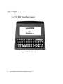
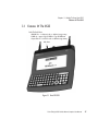
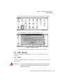
1.3.2 The 8525 Vehicle-Mount Computer
Figure 1.1 8525 With Qwerty Keyboard
8
Psion Teklogix 8525 Vehicle-Mount Computer User Manual
Chapter 1: Introduction
8525 Ports
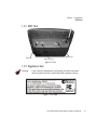
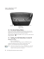
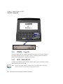
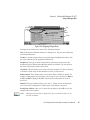
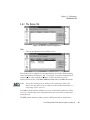
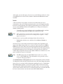
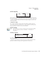
1.3.3 8525 Ports
Auxiliary Port
Tether Port
RS232 Serial Port
Figure 1.2 Ports
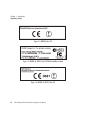
1.3.4 Regulatory Labels
Warning:
Using controls or adjustments or performing procedures other than
those specified herein may result in hazardous radiation exposure.
Figure 1.3 FCC Label
Psion Teklogix 8525 Vehicle-Mount Computer User Manual
9
Chapter 1: Introduction
Regulatory Labels
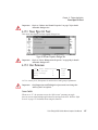
Figure 1.4 RA2020 Label, EU
Figure 1.5 RA2020 & SD-BT2 Label, FCC/IC/Australia/New Zealand
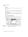
Figure 1.6 RA2020 & SD-BT2 Label, EU
10
Psion Teklogix 8525 Vehicle-Mount Computer User Manual
Chapter 1: Introduction
Regulatory Labels
Figure 1.7 SD-BT2 Label, EU/FCC/IC/Australia/New Zealand
Psion Teklogix 8525 Vehicle-Mount Computer User Manual
11
2
BASIC CHECKOUT
2.1 Preparing The 8525 For Operation . . . . . . . . . . . . . . . .
2.2 Powering Up The 8525 And Configuring The Radio . . . . . . .
2.2.1 Switching The 8525 On. . . . . . . . . . . . . . . . . . .
2.2.2 Configuring An IEEE 802.11 Radio Installed In The 8525
2.2.3 Assigning An IP Address . . . . . . . . . . . . . . . . . .
2.2.4 Name Servers Tab. . . . . . . . . . . . . . . . . . . . . .
2.2.5 Advanced Features . . . . . . . . . . . . . . . . . . . . .
2.2.5.1 Rearranging Preferred Networks . . . . . . . . .
2.2.5.2 Deleting A Preferred Network . . . . . . . . . . .
2.2.5.3 Changing Network Properties . . . . . . . . . . .
2.3 Calibrating The Touchscreen . . . . . . . . . . . . . . . . . . .
2.4 Resetting The 8525 Vehicle-Mount . . . . . . . . . . . . . . . .
.
.
.
.
.
.
.
.
.
.
.
.
.
.
.
.
.
.
.
.
.
.
.
.
.
.
.
.
.
.
.
.
.
.
.
.
.
.
.
.
.
.
.
.
.
.
.
.
.
.
.
.
.
.
.
.
.
.
.
.
15
15
15
15
21
22
23
23
23
24
24
24
Psion Teklogix 8525 Vehicle-Mount Computer User Manual
13
Chapter 2: Basic Checkout
Preparing The 8525 For Operation
2.1 Preparing The 8525 For Operation
Typically, 8525 vehicle-mounts are configured at the factory and arrive ready for
use. Although the 8525 is equipped with an internal Compact Flash, a PCMCIA slot
and SD I/O slot, these slots are not intended for user modification. If a device needs
to be changed or added in these slots, contact qualified Psion Teklogix personnel.
Refer to Appendix A: Support Services And Worldwide Offices for the service
number closest to you.
2.2 Powering Up The 8525 And Configuring The Radio
2.2.1 Switching The 8525 On
To switch the 8525 on:
•
Press the <ENTER/ON> key.
A splash screen displaying the Psion Teklogix logo and the Windows CE .NET logo
appears. When Windows® CE has successfully loaded, the startup desktop is
displayed.
Note: The screen may go blank for a few seconds after the splash screen loading
bar reaches the end. This is part of the normal Windows CE .NET cold
boot process. The desktop is displayed after a few moments.
2.2.2 Configuring An IEEE 802.11 Radio Installed In The 8525
The most common 802.11b settings are configured as defaults. However, there are
some fields that must be completed, including the SSID of your access point and the
security methods implemented in the network (including access keys).
Important:
If the 8525 is equipped with a radio that has never been configured, the radio settings dialogue box opens automatically when
the unit is powered on. In this case, skip to Step 4 on page 17.
Psion Teklogix 8525 Vehicle-Mount Computer User Manual
15
Chapter 2: Basic Checkout
Configuring An IEEE 802.11 Radio Installed In The 8525
To configure the 802.11b radio:
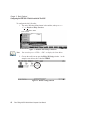
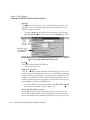
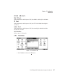
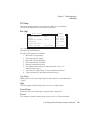
1. Tap on the Windows® Start button in the taskbar, and tap on Settings>Network
and Dial-up Connections.
Figure 2.1 Network And Dial-Up Connections
Note: You can also press <CTRL> <ESC> to display the Start Menu.
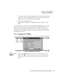
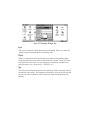
2. Choose the radio icon to open the Wireless LAN Settings window – in the
sample screen below, this is labelled PTXWLAG.
Figure 2.2 Wireless Settings Window
16
Psion Teklogix 8525 Vehicle-Mount Computer User Manual
Chapter 2: Basic Checkout
Configuring An IEEE 802.11 Radio Installed In The 8525
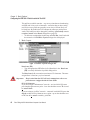
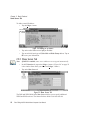
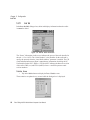
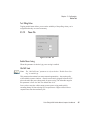
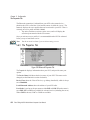
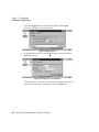
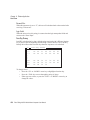
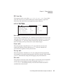
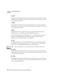
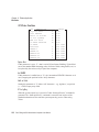
3. Wireless Statistics Tab
When you choose the Wireless LAN icon, a Wireless Statistics window
is displayed.
Figure 2.3 Wireless Statistics
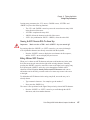
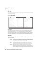
This tab lists your radio statistics. Choosing the Zero button resets the statistics of the last four items – Packets IN, Packets OUT, IN errors and OUT errors.
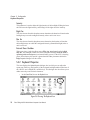
• Tap the stylus on the Wireless Information tab.
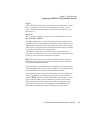
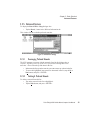
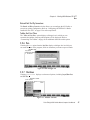
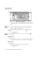
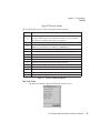
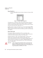
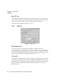
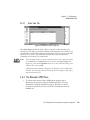
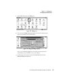
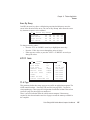
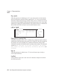
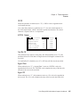
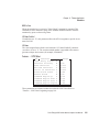
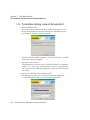
4. Wireless Information Tab
Figure 2.4 Wireless Information Tab
This tab display existing networks to which you can connect, and it allows
you to add a new network or modify the settings for an existing network.
Note: Connect button – To force connection to a specific, existing network,
highlight the network to which you want your 8525 to connect, and tap
the Connect button.
Psion Teklogix 8525 Vehicle-Mount Computer User Manual
17
Chapter 2: Basic Checkout
Configuring An IEEE 802.11 Radio Installed In The 8525
This tab lists available networks – any access points that are broadcasting
an SSID, and it lists preferred networks – networks that you have configured. Since access points are generally secure, they will most likely not
be listed here. By default, the 8525 attempts to connect to preferred networks. This behaviour can be changed by enabling (√) ‘Automatically connect to
non-preferred networks’ in the Advanced dialogue box (page 23).
• To add a new configuration, double-tap on the Add New... item listed with
the networks. A blank Wireless Properties dialogue box is displayed.
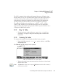
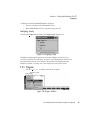
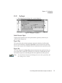
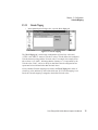
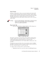
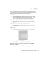
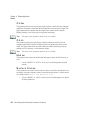
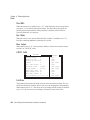
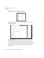
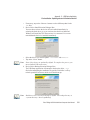
5. Wireless Properties
Figure 2.5 Wireless Properties Dialogue Box
Network name (SSID):
•
Type the appropriate SSID (Service Set Identifier) in the ‘Network name
(SSID):’ text entry field at the top of this dialogue box.
The Network name field can contain a maximum of 32 characters. The name
assigned here is listed as a preferred network.
Important: Keep in mind that the 8525 will only communicate with access
points that are configured with the same SSID.
Ad Hoc And Infrastructure
If you are using an “Infrastructure” network – one in which 8525s must
pass data through an access point – leave the checkbox next to ‘This is an ad
hoc network’ blank.
If you are using an “Ad Hoc” network – a network in which 8525s pass data
directly to other 8525s without an access point – tap on the checkbox next
to ‘This is an ad hoc network’ to enable (√) Ad Hoc.
18
Psion Teklogix 8525 Vehicle-Mount Computer User Manual
Chapter 2: Basic Checkout
Configuring An IEEE 802.11 Radio Installed In The 8525
Encryption
WEP (Wired-Equivalent Privacy) encryption prevents others from accidentally accessing your network. If you are not using encryption, you can
choose ‘Disabled’ from the dropdown encryption menu. Otherwise, leave
this field as is.
Authentication
802.11 supports a number of subtypes of network authentication services:
Open, Shared, WPA and WPA-PSK.
Using Open authentication, any wireless station can request authentication.
The station that needs to authenticate with another wireless station sends an
authentication management frame that contains the identity of the sending
station. The receiving station then sends back a frame that indicates whether
it recognizes the identity of the sending station.
Using Shared authentication, each wireless station is assumed to have
received a secret shared key over a secure channel that is independent from
the 802.11 wireless network communications channel.
WPA (Wi-Fi Protected Access) uses the Temporal Key Integrity Protocol
(TKIP) to provide strong data encryption, and offers two user authentication and key management methods.
The first method of user authentication is intended for environments using a
centralized Authentication Server, such as RADIUS. User authentication is
based on IEEE 802.1X and mutual authentication based EAP.
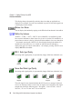
In environments where a centralized Authentication Server or EAP framework is not available, user authentication is based on a ‘Pre-Shared Key’
method – WPA-PSK. If you are using Pre-Shared Key authentication, you will
need to manually enter a password (Master Key) in the Access Point or
Wireless Router and enter the same password in each client device that
accesses the wireless network. The manually configured WPA password
(Master Key) automatically starts the TKIP data encryption process.
Psion Teklogix 8525 Vehicle-Mount Computer User Manual
19
Chapter 2: Basic Checkout
Configuring An IEEE 802.11 Radio Installed In The 8525
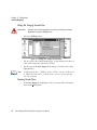
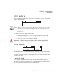
Network Key:
This text box is used to specify a 5 or 13 ASCII character sequence or an
equivalent 10 or 26 Hexadecimal digit sequence that matches the active
WEP key on the access point.
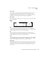
•
To assign a Network key, tap the stylus in the checkbox next to ‘The key is
provided automatically’ to remove the check mark (√) disabling this option.
Disable this option to
access Network Key &
Key Index fields.
Figure 2.6 Accessing Network Key And Key Index
Key Index:
This field is used to identify the WEP key.
• Enter a value from 1 to 4.
Enable 802.1x authentication
“802.1X” is the IEEE standard that offers additional security for local area
networks. It provides authentication for user devices attached to an Ethernet
network, whether wired or wireless. A security protocol packet such as TLS
or MD5 encapsulated in an “EAP” is used in conjunction with the “802.1x”
standard to authenticate users at the MAC layer. Available EAPs are listed
in the dropdown menu next to the ‘EAP’ option.
•
To activate “802.1X”, tap on the checkbox next to ‘Enable 802.1x authentication’, and press the <SPACE> key to enable (√) it.
EAP Type (Extensible Authentication Protocol):
This dropdown menu lists the EAP types available on your system. The
items in this dropdown menu will vary depending on your network setup.
Keep in mind also that some authentication protocols require that you select
20
Psion Teklogix 8525 Vehicle-Mount Computer User Manual
Chapter 2: Basic Checkout
Assigning An IP Address
a ‘Certificate’. By selecting the Properties button, you will be able to select a
Certificate. “Certificate Assignment” on page 84 provides a website that
outlines how to create certificates for your network.
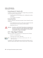
6. Saving and exiting the radio setup.
Once you have completed your configuration, press <ENTER> or tap
on OK.
The connection you created will be listed in the Wireless Information tab as a preferred
network. The radio will search for the SSID and will compare the WEP and
authentication information you specified. If there is a match between your 8525
settings and the access point settings, the 8525 will communicate on the network
through the access point.
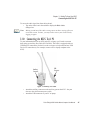
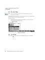
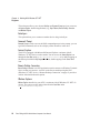
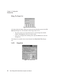
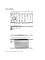
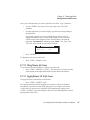
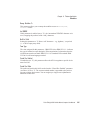
2.2.3 Assigning An IP Address
If your network is not using a DHCP server, you will need to assign an IP address.
Figure 2.7 Configuring An IP Address
Note: Choosing the Renew button forces the 8525 to renew or find a new IP
address. This is useful if, for example, you are out of communication
range for a longer period of time and your 8525 is dropped from the
network.
Psion Teklogix 8525 Vehicle-Mount Computer User Manual
21
Chapter 2: Basic Checkout
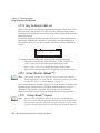
Name Servers Tab
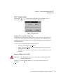
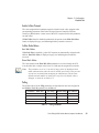
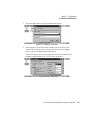
To define a static IP address:
• Tap the Configure... button.
Figure 2.8 Defining An IP Address
•
•
Tap on the radio button next to Specify an IP address.
Tap on each field, and type an IP, Subnet Mask and Default Gateway address. Tap on
OK to save your information.
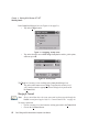
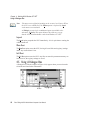
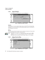
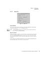
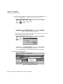
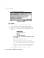
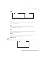
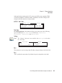
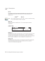
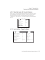
2.2.4 Name Servers Tab
Note: If DHCP is enabled, name server addresses are assigned automatically.
•
•
In the IP Information tab, tap on the Configure... button. (“Figure 2.8” on page 22
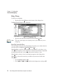
is the window from which you choose the Configure... button.)
Tap on the Name Servers tab.
Figure 2.9 Name Servers Tab
The DNS and WINS fields in the Name Servers tab allow you to specify additional
WINS and DNS resolvers. The format for these fields is ###.###.###.###.
22
Psion Teklogix 8525 Vehicle-Mount Computer User Manual
Chapter 2: Basic Checkout
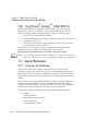
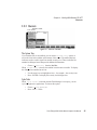
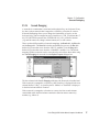
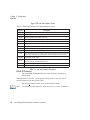
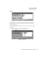
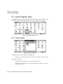
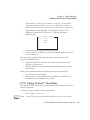
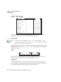
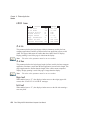
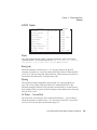
Advanced Features
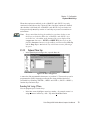
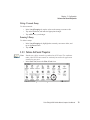
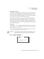
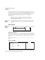
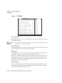
2.2.5 Advanced Features
To display the Advanced Wireless Settings dialogue box:
•
Tap the Advanced... button in the Wireless Information tab.
This window lists the available preferred networks.
Figure 2.10 Advanced Settings
2.2.5.1
Rearranging Preferred Networks
The 8525 attempts to connect with the networks listed in this dialogue box in
sequence, beginning at the top of the list. If you need to rearrange this list of
networks – move networks up and down in the list:
•
•
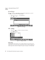
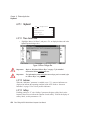
2.2.5.2
In the networks list, tap on the network you want to move up or down in the list.
To move the highlighted item upward or downward in the list, tap the Up or
Down button, and press <ENTER>.
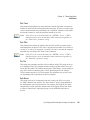
Deleting A Preferred Network
To delete a network from this list:
• Tap on the network in the list to highlight it.
• Tap the Delete button, and press <ENTER>.
Psion Teklogix 8525 Vehicle-Mount Computer User Manual
23
Chapter 2: Basic Checkout
Changing Network Properties
2.2.5.3
Changing Network Properties
To change the properties of an existing preferred network:
• Highlight the network that you want to modify.
• Tap the Properties button, and press <ENTER>.
• Make any necessary changes in the Wireless Properties dialogue box, and press
<ENTER> to save the changes.
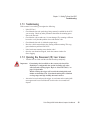
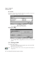
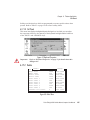
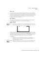
2.3 Calibrating The Touchscreen
Before using your 8525, you will need to calibrate the touchscreen. Refer to
“Calibrating The Touchscreen” on page 32 for details.
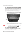
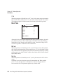
2.4 Resetting The 8525 Vehicle-Mount
Important:
Because Psion Teklogix cannot guarantee what has been saved
(registry) after a reset, this should be considered as a last resort.
To reset the 8525:
•
Press and hold down the <BLUE> key and the <ENTER/ON> key simultaneously for a minimum of six seconds.
A reset results in a complete reboot of the unit. All RAM memory contents are lost.
While it is most likely that the contents of the flash memory and memory card will
be preserved, Psion Teklogix cannot guarantee this. When the 8525 is reset, the
screen displays the Psion Teklogix and Microsoft® Windows® CE. NET splash
screen before displaying the startup desktop.
Note: You do not need to reset your 8525 after configuring the radio.
24
Psion Teklogix 8525 Vehicle-Mount Computer User Manual
3
GETTING TO KNOW YOUR 8525
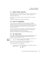
3.1
3.2
3.3
3.4
Features Of The 8525 . . . . . . . . . . . . . . . . . . . . .
The Internal Backup Battery . . . . . . . . . . . . . . . . .
Switching The 8525 Vehicle-Mount On And Off . . . . . . .
The Keyboard . . . . . . . . . . . . . . . . . . . . . . . . .
3.4.1 Modifier Keys. . . . . . . . . . . . . . . . . . . . . .
3.4.1.1 Activating Modifier Keys . . . . . . . . . . .
3.4.1.2 Locking Modifier Keys . . . . . . . . . . . .
3.4.2 The Keys . . . . . . . . . . . . . . . . . . . . . . . .
3.4.3 The Keypad Backlight . . . . . . . . . . . . . . . . .
3.5 The Display . . . . . . . . . . . . . . . . . . . . . . . . . .
3.5.1 Calibrating The Touchscreen . . . . . . . . . . . . . .
3.6 8525 Indicators . . . . . . . . . . . . . . . . . . . . . . . .
3.6.1 LEDs . . . . . . . . . . . . . . . . . . . . . . . . . .
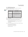
3.6.1.1 PWR/CHG – Charge LED . . . . . . . . . . .
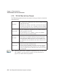
3.6.1.2 RX/TX – Radio Traffic LED. . . . . . . . . .
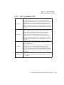
3.6.1.3 Scan LED . . . . . . . . . . . . . . . . . . .
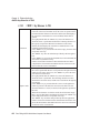
3.6.1.4 API – User Application LED . . . . . . . . .
3.6.2 Onscreen Indicators. . . . . . . . . . . . . . . . . . .
3.6.3 Audio Indicators . . . . . . . . . . . . . . . . . . . .
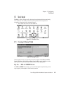
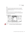
3.7 Scanning. . . . . . . . . . . . . . . . . . . . . . . . . . . .
3.7.1 Scanning Techniques . . . . . . . . . . . . . . . . . .
3.7.2 Scan LED Indicators . . . . . . . . . . . . . . . . . .
3.7.3 Troubleshooting. . . . . . . . . . . . . . . . . . . . .
3.7.4 Operating One Dimensional (1D) Laser Scanners . . .
3.8 Connecting & Disconnecting Tethered Peripherals . . . . . .
3.9 Monitoring The Network Connection. . . . . . . . . . . . .
3.10 Connecting An 8525 To A PC . . . . . . . . . . . . . . . .
3.10.1 Using Microsoft® ActiveSync® To Work With Files .
3.11 General Maintenance . . . . . . . . . . . . . . . . . . . .
3.11.1 Caring For The Touchscreen . . . . . . . . . . . . .
3.11.2 Cleaning The 8525 . . . . . . . . . . . . . . . . . .
.
.
.
.
.
.
.
.
.
.
.
.
.
.
.
.
.
.
.
.
.
.
.
.
.
.
.
.
.
.
.
.
.
.
.
.
.
.
.
.
.
.
.
.
.
.
.
.
.
.
.
.
.
.
.
.
.
.
.
.
.
.
.
.
.
.
.
.
.
.
.
.
.
.
.
.
.
.
.
.
.
.
.
.
.
.
.
.
.
.
.
.
.
.
.
.
.
.
.
.
.
.
.
.
.
.
.
.
.
.
.
.
.
.
.
.
.
.
.
.
.
.
.
.
.
.
.
.
.
.
.
.
.
.
.
.
.
.
.
.
.
.
.
.
.
.
.
.
.
.
.
.
.
.
.
.
.
.
.
.
.
.
.
.
.
.
.
.
.
.
.
.
.
.
.
.
.
.
.
.
.
.
.
.
.
.
.
.
.
.
.
.
.
.
.
.
.
.
.
.
.
.
.
.
.
.
.
.
.
.
.
.
.
.
.
.
.
27
28
28
29
29
30
30
30
32
32
32
33
33
34
34
35
35
35
37
38
38
38
39
39
40
40
41
42
42
42
43
Psion Teklogix 8525 Vehicle-Mount Computer User Manual
25
Chapter 3: Getting To Know Your 8525
Features Of The 8525
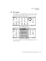
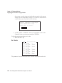
3.1 Features Of The 8525
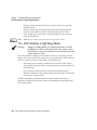
Inside The Radio Dome
- SDIO/MMC Slot – for Bluetooth radio or additional storage memory
- PCMCIA slot - supports 2-Type II PCMCIA or 1-Type III PCMCIA card
- Compact Flash slot - for 802.11b radios or additional storage memory
Radio Dome
Figure 3.1 Front Of 8525
Psion Teklogix 8525 Vehicle-Mount Computer User Manual
27
Chapter 3: Getting To Know Your 8525
The Internal Backup Battery
Tether Port
Auxiliary Port
RS232 Serial Port
Figure 3.2 Ports
3.2 The Internal Backup Battery
The 8525 vehicle-mount is equipped with an internal battery that will provide
backup power to the unit for up to fifteen minutes of normal operation. After 15
minutes, the unit will shut off to preserve the contents of RAM.
The backup battery is not user accessible. It must be replaced by authorized Psion
Teklogix personnel.
3.3 Switching The 8525 Vehicle-Mount On And Off
Switching On The 8525
•
•
Press the <ENTER/ON> key.
When all four LEDs flash orange, release the <ENTER/ON> button.
A splash screen displaying the Psion Teklogix logo and the Microsoft®
Windows CE. NET logo appears followed by the startup desktop.
Note: If the 8525 is in suspend state, pressing <ENTER/ON> key ‘wakes’ the
unit from this state. The screen in which you were working before the
computer entered suspend state is displayed.
28
Psion Teklogix 8525 Vehicle-Mount Computer User Manual
Chapter 3: Getting To Know Your 8525
The Keyboard
Switching Off The 8525
Important:
Keep in mind that turning off the 8525 does not result in a
complete reboot; rather, the unit enters a power-saving,
“suspend” state. When the 8525 is turned on from suspend state,
operation resumes within a few seconds.
To switch off the 8525:
•
Press the <BLUE> key, and then press the <ENTER/ON> key.
Important:
If the word ‘BLUE’ is displayed in uppercase in the taskbar area
at the bottom of the screen, this key is locked “on” – the 8525 will
not switch off. Press the <BLUE> key again to unlock it; then
press <BLUE> <ENTER/ON> to switch the 8525 off.
If, however, you’ve disabled the “Blue Key” in the ‘One Shot’ dialogue box (see “Keyboard One Shot Modes” on page 72), the
8525 can be turned off even when the <BLUE> key is locked ‘on’.
3.4 The Keyboard
The 8525 offers three keyboard layouts – Qwerty, ABC and Azerty. Most of the keys
on these keyboards operate much like a desktop computer. Where a key or key
function is not consistent with the PC keyboard, the differences are noted.
3.4.1 Modifier Keys
The <SHIFT>, <CTRL>, <ALT>, <BLUE> and <ORANGE> keys are modifier
keys. Pressing a modifier key changes the function of the next key pressed. For
example, a square bracket is printed in orange print above the <4> key. Pressing the
<ORANGE> key followed by the <4> key displays a square bracket rather than the
number 4.
The <SHIFT>, <CTRL> and <ALT> keys operate much like a desktop keyboard
except that they are not chorded (two keys held down simultaneously). The modifier
key must be pressed first followed by the key whose function you want modified.
Psion Teklogix 8525 Vehicle-Mount Computer User Manual
29
Chapter 3: Getting To Know Your 8525
Activating Modifier Keys
3.4.1.1
Activating Modifier Keys
When a modifier key is pressed once, it is displayed in lowercase letters in the
taskbar at the bottom of the 8525 screen. For example, if the <CTRL> key is
pressed, ctrl key is displayed at the bottom of the unit screen. Once another key is
pressed, the modifier key becomes inactive and disappears from the taskbar.
3.4.1.2
Locking Modifier Keys
When a modifier key is pressed twice, it is ‘locked’ on. A ‘locked’ modifier key is
displayed in uppercase letters in the taskbar. For example, pressing the <BLUE> key
twice locks it on – it is displayed as BLUE KEY in the taskbar at the bottom of the
computer screen.
The locked modifier key will remain active until it is pressed a third time to unlock
or turn it off. Once a modifier key is unlocked (pressed a third time), the uppercase
representation at the bottom of the screen is no longer displayed.
Note: The locking function of the <ORANGE> and <BLUE> keys can be disabled so that pressing either of these keys once will lock the keys ‘on’.
If you disable the ‘One Shot’ function of either of these keys, pressing the
<BLUE> and/or <ORANGE> key once will lock the key ‘on’. Pressing
the same key a second time will unlock or turn it ‘off’. Refer to “Keyboard
One Shot Modes” on page 72 for details.
3.4.2 The Keys
The <BLUE> And <ORANGE> Keys
The <BLUE> and <ORANGE> modifier keys provide access to additional symbols
and keys. These additional symbols and keys are colour coded in blue and orange
print above the keyboard keys.
Press the <BLUE> key to access functions or characters displayed in blue print on
the keyboard. Press the <ORANGE> key to access functions or characters displayed
in orange print on the keyboard.
The <SHIFT/CAPS> Key
The <SHIFT/CAPS> key is used to display uppercase alpha characters. Pressing
<BLUE><SHIFT> turns the <CAPS> key on so that all alpha characters are printed
in uppercase until the <BLUE><SHIFT> sequence is pressed again.
30
Psion Teklogix 8525 Vehicle-Mount Computer User Manual
Chapter 3: Getting To Know Your 8525
The Keys
The Arrow Keys
The Arrow keys move the cursor around the screen in the direction of the arrow –
up, down, left and right. The cursor is the flashing box or underline character that
indicates where the next character you type will appear.
The <INS> Key
The <INS> key inserts a character at the cursor position.
The <DEL> Key
The <DEL> key erases the character at the cursor position.
The <BKSP> Key
The <BKSP> key (sometimes referred to as destructive backspace) moves the
cursor one character to the left, erasing the incorrectly entered key stroke.
The <CTRL> And <ALT> Key
The <CTRL> and <ALT> keys modify the function of the next key pressed and are
application dependent.
The <TAB> Key
Typically, the <TAB> key moves the cursor to the next field to the right or
downward.
The <ESC> Key
Generally, this key is used as a keyboard shortcut to close the current menu,
dialogue box or activity and return to the previous one.
The <SPACE> Key
Pressing this key inserts a blank space between characters. In a Windows dialogue
box, pressing the <SPACE> key enables (√) or disables a checkbox.
The <HOME> Key
The <HOME> key moves the cursor to the top of the form or page.
The <END> Key
The <END> key moves the cursor to the bottom of the form or page.
Psion Teklogix 8525 Vehicle-Mount Computer User Manual
31
Chapter 3: Getting To Know Your 8525
The Keypad Backlight
The <PgUp> And <PgDn> Keys
The <PgUp> key displays the previous screen of information. The <PgDn> key
displays the next screen of information.
Function Keys And Macro Keys
In addition to alphanumeric keys that are directly accessible on the keyboard (no key
combination is required) and the keys described in this chapter, the 8525 keyboard is
also equipped with thirty function keys and twelve macro keys.
Function keys <F1> through <F30> and Macro keys <M1> to <M12> can be used
with the CE operating system or another application. All function keys and macro
keys can be custom defined for each application. The Tekterm application utilizes
these keys. Refer to “Additional Keyboard Functions” on page 133 for details.
3.4.3 The Keypad Backlight
The intensity of the keypad backlight and the conditions under which this backlight
is activated can be configured using the Keyboard icon in the Windows CE .NET Control
Panel. The behaviour of the keypad backlight is tailored in the Keyboard Properties dialogue
box.
Note: Refer to “Keyboard Backlight” on page 72 for details about this option.
Keep in mind that this option may be restricted to supervisory use only.
3.5 The Display
8525s are equipped with display backlighting to improve character visibility in low
light conditions. The backlight switches on when a key is pressed. The backlight
intensity and the duration of time that the backlight will remain at full intensity can
be specified in the Display Properties dialogue box in the Windows CE .NET Control Panel.
Note: Refer to “Display Backlight” on page 69 for details about the Display
Properties dialogue box.
3.5.1 Calibrating The Touchscreen
If your 8525 touchscreen has never been calibrated or if you find that the stylus
pointer is not accurate when you tap on an item, use the Stylus Properties dialogue box in
the Windows CE .NET Control Panel to recalibrate the screen.
32
Psion Teklogix 8525 Vehicle-Mount Computer User Manual
Chapter 3: Getting To Know Your 8525
8525 Indicators
•
In the Control Panel, choose the Stylus icon to display the Stylus Properties window.
Figure 3.3 Stylus Icon
•
Select the Calibration tab, and then tap on the ‘Recalibrate’ button.
Figure 3.4 Calibration Screen
•
Follow the directions on the calibration screen to calibrate the screen.
3.6 8525 Indicators
8525s use LEDs (Light Emitting Diode), onscreen messages and audio tones as
indicators.
3.6.1 LEDs
The 8525 is equipped with four tri-coloured LEDs. This section outlines what these
LEDs indicate.
Important:
If an LED is illuminated in red, the operator should be cautious
as this generally indicates an abnormal operating condition or
active laser emission.
Psion Teklogix 8525 Vehicle-Mount Computer User Manual
33
Chapter 3: Getting To Know Your 8525
PWR/CHG – Charge LED
LEDs
Figure 3.5 Keyboard LEDs
3.6.1.1
PWR/CHG – Charge LED
The lower-right LED is reserved for internal charger/power status. This LED turns
solid green when the unit is receiving AC power. A blinking green LED indicates
that the unit is taking power from the backup battery.
3.6.1.2
RX/TX – Radio Traffic LED
The upper-left LED on your 8525 flashes either orange or green to indicate when the
radio transmits and receives data.
Note: Keep in mind that while the standard 802.11b radio supports the transmit/receive LED, not all radios support this function.
34
Psion Teklogix 8525 Vehicle-Mount Computer User Manual
Chapter 3: Getting To Know Your 8525
Scan LED
Function
Radio Traffic LED Behaviour
Radio Transmit
Radio Receive
LED flashes orange.
LED flashes green.
Table 3.1 Transmit and Receive LEDs
3.6.1.3
Scan LED
Successful scans are indicated in two ways – with a scan LED and with an
audio tone.
Function
Scan in progress
Successful scan
Unsuccessful scan
Scan LED Behaviour
LED displays solid red during scan.
LED displays solid green after decode.
Off when scan ended.
LED flashes red.
Table 3.2 Scan LED
3.6.1.4
API – User Application LED
This indicator is available for user-loaded custom Windows CE .NET
applications. Refer to the 8525 SDK Manual for details about this LED.
Neither Windows CE .NET nor Tekterm use this LED.
3.6.2 Onscreen Indicators
The taskbar at the bottom of the screen displays a variety of system status indicators.
Figure 3.6 Taskbar
Psion Teklogix 8525 Vehicle-Mount Computer User Manual
35
Chapter 3: Getting To Know Your 8525
Onscreen Indicators
This display changes dynamically, and only those icons that are applicable are
displayed. For example, if a radio is not installed in your 8525, the radio signal icon
is not displayed in the taskbar.
Windows Start Button
You can display the Start Menu by tapping on the Windows® Start button in the taskbar.
Modifier Key Indicators
<SHIFT>, <CTRL>, <ALT>, <BLUE> and <ORANGE> are modifier keys that
have onscreen indicators to show when a key is active or locked. If a modifier key is
pressed once to activate it, the key is displayed in the taskbar in lowercase characters
– for example, pressing the <BLUE> key once displays blue key in the taskbar. If a
modifier key is pressed twice, it is ‘locked on’ and the onscreen indicator is
displayed in uppercase letters in the taskbar – for example, pressing <BLUE> twice
displays BLUE KEY in the taskbar.
802.11 Radio Signal Quality
Increasing radio signal quality is represented by longer, filled bars within this icon.
Good
Reception
Weak
Reception
No Radio
Link
Narrow Band Radio Signal Quality
Increasing radio signal quality is represented by longer, filled bars within this icon.
Good
Reception
Weak
Reception
No Radio
Link
The radio signal is now determined when the 8525 receives a message. If the unit
receives no messages within a second, the "no signal" icon is displayed. The signal
strength icon shows the following cases: "No signal", "1%to 25% bar", "26% to
50% bar", "51% to 75% bar" and "75% to 100% bar".
36
Psion Teklogix 8525 Vehicle-Mount Computer User Manual
Chapter 3: Getting To Know Your 8525
Audio Indicators
Link Status
The Narrow Band radio has three link state icons displayed in the taskbar. An
uppercase ‘LINK’ with a green background indicates the radio is powered on and
that the unit is online and locked onto a channel. A lowercase ‘Link’ with a yellow
background indicates that the radio is powered on but the 8525 is not online or not
locked onto a channel. A lowercase ‘Link’ with a yellow background and a red
‘X’ through it indicates that the radio is not powered on, is not online and is not
locked onto a channel.
Bluetooth Radio
If a Bluetooth radio is installed in your 8525, this icon is displayed in the taskbar.
Security Level
Security levels can be set to limit user access to 8525 settings. In addition,
applications can be restricted to prevent inadvertent changes.
AC Power Icon
This AC icon is displayed in the taskbar when the unit is using AC power.
3.6.3 Audio Indicators
The 8525 beeper provides a variety of sounds and can be configured to emit a sound
when a key is pressed, a keyboard character is rejected, scan input is accepted or
rejected or an operator’s entry does not match in a match field.
Note: Refer to “Volume And Sound Properties” on page 79 for details about
the Volume & Sound Properties dialogue box.
Psion Teklogix 8525 Vehicle-Mount Computer User Manual
37
Chapter 3: Getting To Know Your 8525
Scanning
3.7 Scanning
The scanner used with your unit is configured using the Scanner Properties dialogue box
in the Control Panel.
Note: Refer to “Scanner Properties Setup” on page 114 for details.
The 8525 supports a variety of scanners one dimensional (1D) laser scanners,
“Scanning Techniques” outlines the mechanics of a successful scan. In addition,
review “Scan LED Indicators” on page 38 to better understand how to interpret
whether or not a bar code has been successfully scanned. Finally, “Troubleshooting”
on page 39 provides some helpful suggestions should the scan fail.
3.7.1 Scanning Techniques
Note: External scanners can only be connected to the 8525 tether port.
•
•
•
•
•
Hold the scanner at an angle. Do not hold it perpendicular to the bar code.
Do not hold the scanner directly over the bar code. In this position, light can
reflect back into the scanner’s exit window and prevent a successful decode.
Scan the entire bar code. Make certain that the scan beam crosses every bar
and space on the bar code, including the margins on either end of the
symbol.
Hold the scanner farther away for larger bar codes.
Hold the scanner closer for bar codes with bars that are close together.
3.7.2 Scan LED Indicators
The 8525 scanner LED (the upper-right LED) indicates whether or not your scan is
successful. The LED behaves as follows:
•
•
•
Scan In Progress: scan LED displays solid red colour.
Successful Scan: scan LED displays solid green colour and turns off when
the scan is ended.
Unsuccessful scan: scan LED flashes red.
A bar code icon appears on the screen during a scan. While the scanner beam is
active, the onscreen message states – SCANNING. If the scan is successful, the bar
code data is displayed on the screen until the scan trigger is released.
38
Psion Teklogix 8525 Vehicle-Mount Computer User Manual
Chapter 3: Getting To Know Your 8525
Troubleshooting
3.7.3 Troubleshooting
If the scanner is not working, investigate the following:
• Is the 8525 on?
• Check that the bar code symbology being scanned is enabled for the 8525
you are using. Check any other parameters that affect the scanning procedure or the bar code.
• Check the bar code to make sure it is not damaged. Try scanning a different
bar code to verify that the problem is not with the bar code.
• Check that the bar code is within the proper range.
• Does the vehicle-mount display the warning without scanning? This suggests a hardware problem in the 8525.
• Is the laser beam scanning across the bar code?
• Once the scan beam has stopped, check the scanner window for
dirt or fogging.
3.7.4 Operating One Dimensional (1D) Laser Scanners
•
Turn the 8525 on. Wait until the unit has booted up completely.
Important:
•
If an aiming dot is available on the scanner, the dot will be
enabled for a configurable time period (including off), after
which normal scanning begins. Refer to “Dot Time (msec)” on
page 116 for details.
Double-clicking the trigger will override the aiming delay and
initiate an immediate scan. Note that the aiming dot is standard
on long-range and high visibility internal scanners.
Aim at the bar code and press the trigger. A scan beam and a warning indicator appear until a successful decode is achieved or six seconds have
elapsed.
Psion Teklogix 8525 Vehicle-Mount Computer User Manual
39
Chapter 3: Getting To Know Your 8525
Connecting & Disconnecting Tethered Peripherals
3.8 Connecting & Disconnecting Tethered Peripherals
Tethered peripherals such as scanners and printers connect to the vehicle-mount
computer with a quick release, circular connector. When a peripheral is connected to
the vehicle-mount, the 8525 detects the peripheral and loads the necessary drivers
for it. An icon in the taskbar at the bottom of the screen provides a visual
representation of the peripheral and indicates that it is ready for operation.
To attach the peripheral to the round, tether port on the side of the 8525:
•
Insert the barrel of the plug into the tether port and rotate slowly until it clicks
into place. The red dot on the port and on the connector should be aligned.
Tether Port
Figure 3.7 The Tether Port
To remove the peripheral:
•
Grasp the shell of the plug, and pull it back gently to unlock and release the
connector.
Important:
Never attempt to disconnect a peripheral by pulling the connector
by the wire. The connector is locked into place and can only be
unlocked and removed by pulling back the plug shell.
3.9 Monitoring The Network Connection
If your vehicle-mount is equipped with a wireless LAN radio, it will typically
associate with the nearest access point. The radio signal quality meter in the taskbar
indicates the relative strength of the communication link.
40
Psion Teklogix 8525 Vehicle-Mount Computer User Manual
Chapter 3: Getting To Know Your 8525
Connecting An 8525 To A PC
To access the radio signal icon from the keyboard:
•
Tap on the radio icon in the taskbar to display the Wireless Statistics
dialogue box.
Note: Moving in and out of the radio coverage area can have varying effects on
a network session. At times, you may need to renew your connection by
logging in again.
3.10 Connecting An 8525 To A PC
To pass information between an 8525 and a PC or laptop, you’ll need to connect
them using an Auxiliary Port Cable (PN CA2200). This cable is equipped with two
USB Host I/F connections (for devices such as a mouse or keyboard) and one USB
Device I/F connection (to, for example, connect a PC or laptop computer to the
8525).
Auxiliary
Connector
USB
Connector
Figure 3.8 Auxiliary Port Cable
•
•
Attach the auxiliary connector to the auxiliary port on the 8525 – the port
closest to the vehicle-mount power cable.
Attach the USB connector to your PC or laptop.
Psion Teklogix 8525 Vehicle-Mount Computer User Manual
41
Chapter 3: Getting To Know Your 8525
Using Microsoft® ActiveSync® To Work With Files
3.10.1 Using Microsoft® ActiveSync® To Work With Files
Before communication can begin between an 8525 and a PC, ActiveSync® –
Microsoft PC connectivity software – must be installed on your PC. Once the
devices are cabled together, running ActiveSync on the PC will allow you to:
• View 8525 files from Windows Explorer.
• Drag and drop files between the 8525 and the PC in the same way that you
would between PC drives.
• Back up 8525 files to the PC, then restore them from the PC to the vehicle-mount again, if needed, and so on.
To install ActiveSync, follow the step-by-step instructions provided with the
program’s setup wizard. Refer to the following website for details:
http://www.microsoft.com/windowsmobile/resources/downloads/pocketpc/activesync35.mspx
Note: You’ll need the USB setup utility to configure the .ini file. For information
about this USB application, refer to Appendix C: USB Setup Application.
3.11 General Maintenance
3.11.1 Caring For The Touchscreen
The top of the touchscreen is a thin, flexible polyester plastic sheet with a
conductive coating on the inside. The polyester can be permanently damaged by
harsh chemicals and is susceptible to abrasions and scratches. Using sharp objects
on the touchscreen can scratch or cut the plastic, or crack the internal conductive
coating.
If the touchscreen is used in harsh environments, consider applying a disposable
screen protector (PN 1008009). These covers reduce the clarity of the display
slightly but will dramatically extend the useful life of the touchscreen. When they
become scratched and abraded, they are easily removed and replaced.
The chemicals listed below must not come into contact with the touchscreen:
• mustard,
• sodium hydroxide,
• concentrated caustic solutions,
• benzyl alcohol, and
• concentrated miner acids.
42
Psion Teklogix 8525 Vehicle-Mount Computer User Manual
Chapter 3: Getting To Know Your 8525
Cleaning The 8525
3.11.2 Cleaning The 8525
Important:
•
•
•
Do not immerse the unit in water. Dampen a soft cloth with mild
detergent to wipe the unit clean.
Use only mild detergent or soapy water to clean the vehicle-mount unit.
Avoid abrasive cleaners, solvents or strong chemicals for cleaning.
To clean ink marks from the keypad and touchscreen, use isopropyl
alcohol.
Psion Teklogix 8525 Vehicle-Mount Computer User Manual
43
4
WORKING WITH WINDOWS CE .NET
4.1 Navigating In Windows CE .NET And Applications
4.1.1 Navigating Using A Touchscreen And Stylus
4.1.2 Navigating Using The Keyboard . . . . . . .
4.2 Working With Files, Folders And Programs . . . .
4.3 The Startup Desktop . . . . . . . . . . . . . . . .
4.3.1 The Desktop Icons . . . . . . . . . . . . . .
4.3.2 The Taskbar . . . . . . . . . . . . . . . . . .
4.3.2.1 Using The Taskbar . . . . . . . . . .
4.3.2.2 Customizing The Taskbar . . . . . .
4.4 The Start Menu . . . . . . . . . . . . . . . . . . .
4.4.1 The Desktop . . . . . . . . . . . . . . . . .
4.4.2 Security Levels . . . . . . . . . . . . . . . .
The System Tray . . . . . . . . . . . . . . . . . .
The Task Manager . . . . . . . . . . . . . . . . .
Cycle Tasks. . . . . . . . . . . . . . . . . . . . .
4.4.3 Programs . . . . . . . . . . . . . . . . . . .
4.4.5 Settings . . . . . . . . . . . . . . . . . . . .
4.4.6 Run . . . . . . . . . . . . . . . . . . . . . .
4.4.7 Shutdown . . . . . . . . . . . . . . . . . . .
4.5 Using A Dialogue Box . . . . . . . . . . . . . . .
.
.
.
.
.
.
.
.
.
.
.
.
.
.
.
.
.
.
.
.
.
.
.
.
.
.
.
.
.
.
.
.
.
.
.
.
.
.
.
.
.
.
.
.
.
.
.
.
.
.
.
.
.
.
.
.
.
.
.
.
.
.
.
.
.
.
.
.
.
.
.
.
.
.
.
.
.
.
.
.
.
.
.
.
.
.
.
.
.
.
.
.
.
.
.
.
.
.
.
.
.
.
.
.
.
.
.
.
.
.
.
.
.
.
.
.
.
.
.
.
.
.
.
.
.
.
.
.
.
.
.
.
.
.
.
.
.
.
.
.
.
.
.
.
.
.
.
.
.
.
.
.
.
.
.
.
.
.
.
.
.
.
.
.
.
.
.
.
.
.
.
.
.
.
.
.
.
.
.
.
.
.
.
.
.
.
.
.
.
.
.
.
.
.
.
.
.
.
.
.
.
.
.
.
.
.
.
.
.
.
.
.
.
.
.
.
.
.
.
.
.
.
.
.
.
.
.
.
.
.
.
.
.
.
.
.
.
.
.
.
45
45
46
47
47
48
48
49
49
50
50
51
55
56
55
53
56
57
57
58
Psion Teklogix 8525 Vehicle-Mount Computer User Manual
43
Chapter 4: Working With Windows CE .NET
Navigating In Windows CE .NET And Applications
4.1 Navigating In Windows CE .NET And Applications
Graphic user interfaces like Windows CE .NET for portable devices and desktop
Windows (2000, XP, etc.) utilize ‘point and click’ navigation. An equivalent
keyboard shortcut is also available for every ‘point and click’ action.
Windows CE .NET supports the same ‘point and click’ user interface and keyboard
shortcuts as desktop Windows with one difference – the ‘point and click’ action is
accomplished using a touchscreen rather than a mouse. Actions can be performed
using any combination of keyboard shortcuts or touchscreen tapping (provided your
8525 is equipped with a touchscreen).
4.1.1 Navigating Using A Touchscreen And Stylus
Note: If the touchscreen is not registering your screen taps accurately, it may
need recalibration. Refer to “Calibrating The Touchscreen” on page 32.
An 8525 equipped with a touchscreen has a stylus – a pointing tool that looks like a
pen – that is used to select objects on the touchscreen.
Note: To prevent damage to the touchscreen, use only the stylus (pen)
supplied with your 8525.
To open a file, launch an applet or open a folder:
•
Double-tap the stylus on the appropriate icon.
To navigate through a dialogue box – for example, display the information in a tab,
choose a radio button, check (√) a checkbox and so on:
•
Tap the stylus on a tab, radio button, checkbox and so on.
Psion Teklogix 8525 Vehicle-Mount Computer User Manual
45
Chapter 4: Working With Windows CE .NET
Navigating Using The Keyboard
4.1.2 Navigating Using The Keyboard
If your touchscreen has been disabled, you can use the keyboard rather than a stylus
to choose icons and navigate dialogue boxes, display the desktop, and so on. If your
unit has already been fully configured and your application is launched at startup,
you’ll have little need for keyboard navigation.
Operation
Key or Key Combination
Switch between active applications
Open task manager
Move the cursor
Open file, folder or icon
Exit & Save
Close/Exit & Do Not Save
Navigate Dialogue Boxes
Select Radio Button/Press Button
Go to Start Menu
<ALT> <TAB>
<ALT> <ESC>
Arrow keys
<ENTER>
<ENTER>
<ESC>
<TAB>
To move cursor up <SHIFT> <TAB>
To display the contents of the next ‘tab’ in
a dialogue box <CTRL> <TAB>
<SPACE>
<BLUE><0>
Table 4.1 Keyboard Navigation
Keep in mind that unlike a desktop computer, the 8525 does not support key
chording (pressing two keys at the same time). You must press one key followed by
the next in sequence.
Refer to “Working With Files, Folders And Programs” on page 47 for additional
details about keyboard navigation.
46
Psion Teklogix 8525 Vehicle-Mount Computer User Manual
Chapter 4: Working With Windows CE .NET
Working With Files, Folders And Programs
4.2 Working With Files, Folders And Programs
Figure 4.1 Working With Windows Icons
•
Double-tap on the appropriate icon – either a folder icon, a program icon or
a file icon – to open or launch your selection.
4.3 The Startup Desktop
When the 8525 boots up, the startup desktop (shell) is displayed. Any applications
stored in the Startup folder start up immediately.
Note: The startup folder is located in \Windows\StartUp and
\Flash Disk\StartUp.
Figure 4.2 The 8525 Startup Desktop
•
Double-tap on the icon to open a window or, in the case of an application
icon, launch an application.
Psion Teklogix 8525 Vehicle-Mount Computer User Manual
47
Chapter 4: Working With Windows CE .NET
The Desktop Icons
4.3.1 The Desktop Icons
The icons displayed in the startup desktop operate in much the same way as those
displayed on any standard PC desktop that is running Windows®.
My Computer
Choosing this icon displays the contents of your 8525 computer. If you’re not sure
how to work with the files, folders and programs displayed, refer to “Working With
Files, Folders And Programs” on page 47.
Recycle Bin
This option temporarily contains items that were deleted, allowing you to either
permanently delete or restore these items.
Internet Explorer
Choosing this icon launches Internet Explorer – a standard Windows CE .NET
version. Keep in mind that your supervisor will need to set up access using the
Internet Options and the Network and Dial-up Connections icons in the Control Panel.
Remote Desktop Connection
This option allows your 8525 to communicate with a remote desktop PC. “Remote
Desktop Connection” on page 63 provides a website with step-by-step instructions.
4.3.2 The Taskbar
Figure 4.3 The Taskbar
48
Psion Teklogix 8525 Vehicle-Mount Computer User Manual
Chapter 4: Working With Windows CE .NET
Using The Taskbar
The 8525 is equipped with a taskbar at the bottom of the screen. It displays icons
through which you can view the internal battery capacity, the radio signal quality of
your unit, and so on. If the vehicle-mount is attached to a peripheral device, an
associated icon is displayed. In addition, the taskbar displays the application(s)
currently running on your unit and the security level assigned to your 8525.
The taskbar also displays active modifier keys – <SHIFT>, <ALT>, <CTRL>,
<BLUE> and <ORANGE>. Keys that have been locked “on” are displayed in
uppercase letters. For example, if you press the <CTRL> key twice to lock it “on”, it
is displayed as CTRL KEY in the taskbar.
4.3.2.1
•
4.3.2.2
Using The Taskbar
Using the stylus, tap on the indicator you want to view – the radio icon
for example – to display a dialogue box outlining radio communication
information.
Customizing The Taskbar
To customize the taskbar so that it displays only those icons you require:
•
From the Start Menu, tap on the Settings option, and then on the Taskbar
and Start Menu option
The Taskbar and Start Menu dialogue box is displayed.
Figure 4.4 Taskbar And Start Menu Settings
•
Tap the stylus on the items you want to activate or deactivate. A check mark
indicates active items.
Note: The Advanced tab allows you to tap on a Clear button to delete the contents of
the Documents folder.
Psion Teklogix 8525 Vehicle-Mount Computer User Manual
49
Chapter 4: Working With Windows CE .NET
The Start Menu
4.4 The Start Menu
Note: Some of the Start Menu items may be disabled based on the 8525’s
current security settings.
The Start Menu lists the operations you can access and work with. It is available from
the startup desktop or from within any application.
To display the menu:
• Tap on the Windows® Start button in the taskbar. Tap on the item in the
menu with which you want to work.
Figure 4.5 Start Menu
4.4.1 The Desktop
Choosing the Desktop option from the Start Menu displays the 8525 desktop.
50
Psion Teklogix 8525 Vehicle-Mount Computer User Manual
Chapter 4: Working With Windows CE .NET
Security Levels
4.4.2 Security Levels
Choosing the Security option from the Start Menu displays a dialogue box in
which you can define the access level for the 8525 – Supervisor or User.
Figure 4.6 Security Level
Assigning The Supervisor Security Level
The security level is represented by an icon in the shape of a lock in the taskbar. The
security levels define the options accessible to the operator in the Start Menu and the
taskbar. By default, the security level is set to User, restricting access to only the most
basic Start Menu items.
To allow access to all the Start Menu and taskbar options:
•
•
•
Tap on the radio button next to Supervisor.
Tap the stylus in the Password field, and type the Supervisor level password –
default password is 123456.
Tap on OK – you can now access all menu items in the Start Menu and icons in
the taskbar.
Accessing Teklogix Level Security
Important:
The Teklogix security level is reserved for authorized Psion Teklogix personnel only.
Before you can access Teklogix security level, you need to set the security level
to Supervisor.
Psion Teklogix 8525 Vehicle-Mount Computer User Manual
51
Chapter 4: Working With Windows CE .NET
Security Levels
In the Security Level dialogue box (see Figure 4.6 on page 51):
•
Tap on the Configure button.
Figure 4.7 Configuring Security Levels
•
Tap on the checkbox next to Allow Teklogix Security Level to enable (√) this option,
and then tap on OK.
Figure 4.8 Security Levels
The Teklogix level security is now available in the Security Level dialogue box.
•
Tap on the radio button next to Teklogix. To activate this security level,
you’ll need to enter the appropriate Psion Teklogix level password in
the Password field.
Changing A Password
Note: Keep in mind that this is the same password as that assigned through the
Password control panel applet. Refer to “Control Panel Icons” on page 64.
To assign a password:
• Choose a security level, and enter the existing password in the Password field
• Choose the Set Password button.
52
Psion Teklogix 8525 Vehicle-Mount Computer User Manual
Chapter 4: Working With Windows CE .NET
Programs
A dialogue box labelled Password Properties is displayed.
•
•
Type the new password in the Password: text box
In the Confirm Password: text box, retype the new password.
Configuring Security
Choosing the Configure button displays the Configure Security dialogue box.
Figure 4.9 Configuring Security
In addition to allowing the operator to access the Teklogix security level (see
“Accessing Teklogix Level Security” on page 51), this dialogue box allows you to
determine which security levels will have an associated icon displayed in the
taskbar. By default, a security icon is not displayed for user-level security.
4.4.3 Programs
•
Tap on Programs to display a sub-menu of options.
Figure 4.10 Program Sub-Menu
Psion Teklogix 8525 Vehicle-Mount Computer User Manual
53
Chapter 4: Working With Windows CE .NET
Programs
This sub-menu allows you to choose ActiveSync and Command Prompt, and you can access
the Internet Explorer, installed applications (e.g., Open Tekterm), Remote Desktop Connection
and Windows Explorer.
ActiveSync®
This option allows you to connect to another device using ActiveSync.
Command Prompt
Command Prompt is used to access the DOS command prompt. At the prompt, you can
type DOS commands such as dir to display all the directories in the drive.
Internet Explorer
The 8525 is equipped with Microsoft® Internet Explorer consistent with all
Windows CE .NET devices on the market. You can access the Internet Options icon
through the Start Menu under Settings>Control Panel or by double-tapping on
the desktop icon labelled My Computer and then, double-tapping on the Control Panel
icon.
Remote Desktop Connection
Remote Desktop Connection is an 8525 application used to connect to a Windows Terminal
Server so that you can run a “session” on the Server machine using the 8525
(Windows CE .NET device). “Remote Desktop Connection” on page 63 provides a
website with details about this option.
Windows Explorer
Windows Explorer installed on your 8525 is consistent with all Windows CE .NET 4.2
devices. You can access this option either from the Start Menu under
Programs>Windows Explorer.
54
Psion Teklogix 8525 Vehicle-Mount Computer User Manual
Chapter 4: Working With Windows CE .NET
Shortcuts
4.4.4 Shortcuts
Figure 4.11 Shortcuts Sub-Menu
The System Tray
If your touchscreen is not enabled, you can use the System Tray option to
access the icons in the taskbar at the bottom of the screen. The taskbar displays
indicators such as a radio signal icon and the security level. These indicators are
attached to dialogue boxes that provide additional information.
• Choose System Tray from the Start Menu.
When System Tray is chosen, the taskbar icons become accessible. To display
the dialogue box attached to an icon:
•
•
Use the arrow keys to highlight an icon – for example – the security icon.
Press <ENTER> to display the security level dialogue box.
Cycle Tasks
When Cycle Tasks is selected (and the Task Manager is not open), you can
cycle through active applications. To choose this option:
•
•
Choose Cycle Tasks, or
Press <ALT> <TAB>.
Psion Teklogix 8525 Vehicle-Mount Computer User Manual
55
Chapter 4: Working With Windows CE .NET
Settings
The Task Manager
The Task Manager option allows you to switch to another task or to end an
active task. To display the task manager window:
•
•
Tap on Task Manager in the Start Menu, or
Press <ALT> <ESC>.
Figure 4.12 Task Manager
4.4.5 Settings
•
Tap on Settings to display a sub-menu of options.
Figure 4.13 Settings Sub-Menu
Control Panel
The Control Panel contains applets used to configure hardware, the operating system
and the shell. If your 8525 is running with the Psion Teklogix Tekterm application or
another application, additional configuration applets may appear in the Control Panel.
56
Psion Teklogix 8525 Vehicle-Mount Computer User Manual
Chapter 4: Working With Windows CE .NET
Run
Network And Dial-Up Connections
The Network and Dial-up Connections window allows you to configure the 8525 radio or
execute an existing configuration. Refer to “Configuring An IEEE 802.11 Radio
Installed In The 8525” on page 15 for radio setup details.
Taskbar And Start Menu
The Taskbar and Start Menu option displays a dialogue box in which you can
customize the taskbar, choosing which options will be displayed. Refer to
“Customizing The Taskbar” on page 49 for additional details about this option.
4.4.6 Run
Choosing the Run option from the Start Menu displays a dialogue box in which you
can enter the name of the program, folder or document you want to open or launch.
Figure 4.14 Run Dialogue Box
4.4.7 Shutdown
Choosing Shutdown displays a sub-menu of options, including Suspend, Warm Reset
and Cold Reset.
Figure 4.15 Shutdown Sub-Menu
Psion Teklogix 8525 Vehicle-Mount Computer User Manual
57
Chapter 4: Working With Windows CE .NET
Using A Dialogue Box
Note: This menu varies slightly depending on the security level chosen. When
the 8525 is set to User level, the Shutdown option is replaced by Suspend.
A sub-menu is not available.
At Teklogix security level, an additional option is available in the
sub-menu – Bootloader. This option behaves like cold-reset, except
that the 8525 starts Bootloader rather than Windows CE .NET.
Suspend
The Suspend option suspends the 8525 immediately – this is equivalent to turning the
vehicle-mount off.
Warm Reset
The Warm Reset option resets the 8525, leaving all saved files and (registry) settings
intact. Any unsaved data is lost.
Cold Reset
The Cold Reset option resets the 8525. Any files not stored in permanent memory are
lost. However, the registry settings are saved.
4.5 Using A Dialogue Box
A dialogue box (like the samples in Figure 4.16) appears when you need to make
selections and enter further information.
Checkbox
58
Dropdown Menu
Psion Teklogix 8525 Vehicle-Mount Computer User Manual
Button
Chapter 4: Working With Windows CE .NET
Using A Dialogue Box
Tabs
Radio
Button
Textbox
Figure 4.16 Navigating Dialogue Boxes
Dialogue boxes contain one or more of the following elements:
Tab: A tab separates different elements of a dialogue box. Tap on a tab to display the
associated information.
Textbox: A textbox requires that you type information. Highlight the textbox with
the stylus and then type the appropriate information.
Dropdown: This type of menu is identified by up and down arrows next to the
dropdown menu to indicate that additional options are available. Tap the stylus on
the arrow to display the options in the menu.
Checkbox: This box allows you to select or deselect an option. To select or deselect
a checkbox, tap the stylus on the checkbox to select (√) or deselect it.
Radio buttons: These buttons allow you to choose from a number of options. For
example, in the sample screen in Figure 4.16 on page 59 you can choose to ‘Obtain an
IP address via DHCP’ or ‘Specify an IP address’. Tap the stylus on the button to select or
deselect it.
Buttons: This type of button allows you to ‘Save’, ‘Delete’ and so on the options
you’ve chosen in a dialogue box. Tap the stylus on the button to activate it.
Saving Your Choices: Once you’ve made all your changes, tap on OK to save your
changes and exit the window.
Note: A dialogue box item that is displayed in grey text indicates that it is not
currently available.
Psion Teklogix 8525 Vehicle-Mount Computer User Manual
59
5
CONFIGURATION
5.1
5.2
5.3
5.4
5.5
Remote Desktop Connection . . . . . . . . . . . . .
Pocket PC Compatibility . . . . . . . . . . . . . . .
The Control Panel . . . . . . . . . . . . . . . . . . .
Control Panel Icons . . . . . . . . . . . . . . . . . .
Basic Setup . . . . . . . . . . . . . . . . . . . . . .
5.5.1 Display Properties . . . . . . . . . . . . . . .
5.5.1.1 Display Background . . . . . . . . . .
5.5.1.2 Display Appearance . . . . . . . . . .
5.5.1.3 Display Backlight . . . . . . . . . . .
5.5.2 Keyboard Properties . . . . . . . . . . . . . .
5.5.2.1 Key Repeat. . . . . . . . . . . . . . .
5.5.2.2 Keyboard Backlight . . . . . . . . . .
5.5.2.3 Keyboard One Shot Modes . . . . . .
5.5.2.4 Keyboard Macro Keys . . . . . . . . .
5.5.2.5 Unicode Mapping . . . . . . . . . . .
5.5.2.6 Scancode Remapping . . . . . . . . .
5.5.3 Volume And Sound Properties . . . . . . . . .
5.5.3.1 Volume Adjustments . . . . . . . . . .
5.5.4 Power Management Properties . . . . . . . . .
5.5.4.1 Power Suspend. . . . . . . . . . . . .
5.5.4.2 Card Slots . . . . . . . . . . . . . . .
5.5.5 Stylus Properties . . . . . . . . . . . . . . . .
5.5.5.1 Setting Double-Tap Sensitivity . . . .
5.5.5.2 Touchscreen Calibration . . . . . . . .
5.5.5.3 Options – Disabling The Touchscreen .
5.5.6 Certificate Assignment . . . . . . . . . . . . .
5.5.7 Narrow Band Radio. . . . . . . . . . . . . . .
5.5.7.1 Info Tab . . . . . . . . . . . . . . . .
5.5.7.2 Channel Tab . . . . . . . . . . . . . .
5.5.7.3 Protocol Tab . . . . . . . . . . . . . .
5.5.7.4 Power Tab . . . . . . . . . . . . . . .
5.5.7.5 Radio Tab . . . . . . . . . . . . . . .
5.6 Bluetooth Setup . . . . . . . . . . . . . . . . . . . .
.
.
.
.
.
.
.
.
.
.
.
.
.
.
.
.
.
.
.
.
.
.
.
.
.
.
.
.
.
.
.
.
.
.
.
.
.
.
.
.
.
.
.
.
.
.
.
.
.
.
.
.
.
.
.
.
.
.
.
.
.
.
.
.
.
.
.
.
.
.
.
.
.
.
.
.
.
.
.
.
.
.
.
.
.
.
.
.
.
.
.
.
.
.
.
.
.
.
.
.
.
.
.
.
.
.
.
.
.
.
.
.
.
.
.
.
.
.
.
.
.
.
.
.
.
.
.
.
.
.
.
.
.
.
.
.
.
.
.
.
.
.
.
.
.
.
.
.
.
.
.
.
.
.
.
.
.
.
.
.
.
.
.
.
.
.
.
.
.
.
.
.
.
.
.
.
.
.
.
.
.
.
.
.
.
.
.
.
.
.
.
.
.
.
.
.
.
.
.
.
.
.
.
.
.
.
.
.
.
.
.
.
.
.
.
.
.
.
.
.
.
.
.
.
.
.
.
.
.
.
.
.
.
.
.
.
.
.
.
.
.
.
.
.
.
.
.
.
.
.
.
.
.
.
.
.
.
.
.
.
.
.
.
.
.
.
.
.
.
.
.
.
.
.
.
.
.
.
.
.
.
.
.
.
.
.
.
.
.
.
.
.
.
.
.
.
.
.
.
.
.
.
.
.
.
.
.
.
.
.
.
.
.
.
.
.
.
.
.
.
.
.
.
.
.
.
.
.
.
.
.
.
.
.
.
.
.
.
.
.
.
.
.
.
.
.
.
.
.
.
.
.
.
.
.
.
.
.
.
.
.
.
.
63
63
63
64
68
68
68
69
69
70
71
72
72
73
75
77
79
80
80
81
82
82
83
83
84
84
85
86
89
92
95
96
98
Psion Teklogix 8525 Vehicle-Mount Computer User Manual
61
Chapter 5: Configuration
5.6.1 The Devices Tab. . . . . . . . .
5.6.2 The Server Tab . . . . . . . . .
5.6.3 The Properties Tab . . . . . . .
5.6.3.1 Active Conn. Tab . . . .
5.6.4 The Bluetooth GPRS Phone. . .
5.7 Total Recall . . . . . . . . . . . . . .
5.7.1 Creating A Backup Profile . . .
5.7.2 Restoring A Profile . . . . . . .
5.8 IPv6 Support . . . . . . . . . . . . . .
5.9 Scanner Properties Setup . . . . . . .
5.9.1 Scanner Options . . . . . . . . .
5.9.2 Bar Codes . . . . . . . . . . . .
5.9.2.1 Code 39 Settings . . . .
5.9.2.2 Code 128 Settings . . .
5.9.2.3 EAN 13 Settings . . . .
5.9.2.4 EAN 8 . . . . . . . . .
5.9.2.5 UPC And EAN Settings
5.9.2.6 UPC A Settings. . . . .
5.9.2.7 UPC E Settings . . . . .
5.9.2.8 Codabar. . . . . . . . .
5.9.2.9 Code 93. . . . . . . . .
5.9.2.10 Code 11 . . . . . . . .
5.9.2.11 Interleaved 2 of 5 . . .
5.9.2.12 MSI Plessey . . . . . .
5.9.2.13 Discrete 2 of 5 . . . .
5.9.2.14 IATA 2 of 5 . . . . . .
5.9.3 Translations . . . . . . . . . . .
62
.
.
.
.
.
.
.
.
.
.
.
.
.
.
.
.
.
.
.
.
.
.
.
.
.
.
.
Psion Teklogix 8525 Vehicle-Mount Computer User Manual
.
.
.
.
.
.
.
.
.
.
.
.
.
.
.
.
.
.
.
.
.
.
.
.
.
.
.
.
.
.
.
.
.
.
.
.
.
.
.
.
.
.
.
.
.
.
.
.
.
.
.
.
.
.
.
.
.
.
.
.
.
.
.
.
.
.
.
.
.
.
.
.
.
.
.
.
.
.
.
.
.
.
.
.
.
.
.
.
.
.
.
.
.
.
.
.
.
.
.
.
.
.
.
.
.
.
.
.
.
.
.
.
.
.
.
.
.
.
.
.
.
.
.
.
.
.
.
.
.
.
.
.
.
.
.
.
.
.
.
.
.
.
.
.
.
.
.
.
.
.
.
.
.
.
.
.
.
.
.
.
.
.
.
.
.
.
.
.
.
.
.
.
.
.
.
.
.
.
.
.
.
.
.
.
.
.
.
.
.
.
.
.
.
.
.
.
.
.
.
.
.
.
.
.
.
.
.
.
.
.
.
.
.
.
.
.
.
.
.
.
.
.
.
.
.
.
.
.
.
.
.
.
.
.
.
.
.
.
.
.
.
.
.
.
.
.
.
.
.
.
.
.
.
.
.
.
.
.
.
.
.
.
.
.
.
.
.
.
.
.
.
.
.
.
.
.
.
.
.
.
.
.
.
.
.
.
.
.
.
.
.
.
.
.
.
.
.
.
.
.
.
.
.
.
.
.
.
.
.
.
.
.
.
.
.
.
.
.
.
.
.
.
.
.
.
.
.
.
.
.
.
.
.
.
.
.
.
.
.
.
.
.
.
.
.
.
.
.
.
.
.
.
.
.
.
.
.
.
.
.
.
.
.
.
.
.
.
.
.
.
.
.
.
.
.
.
.
.
.
.
.
.
.
.
.
.
.
.
.
.
.
.
.
.
.
.
.
.
.
.
.
.
.
.
.
.
.
.
.
.
.
.
.
.
.
.
.
.
.
.
.
.
.
.
.
.
.
.
.
.
.
.
.
.
.
.
.
.
.
.
.
.
.
.
.
.
.
.
.
.
.
.
.
.
.
.
.
.
.
. 99
101
102
103
103
109
109
112
113
114
114
117
118
120
121
122
123
123
124
124
124
125
125
126
126
127
127
Chapter 5: Configuration
Remote Desktop Connection
5.1 Remote Desktop Connection
Remote Desktop Connection is an 8525 application used to connect to a Windows Terminal
Server so that you can run a “session” on the Server machine, using the 8525
(Windows CE .NET device).
Refer to the following website for step-by-step information about setting up this
connection:
http://www.microsoft.com/WindowsXP/pro/using/howto/gomobile/remotedesktop/default.asp
5.2 Pocket PC Compatibility
The 8525 supports the AYGShell API set that allows PocketPC-compatible
applications to run on the vehicle-mount. Microsoft® Windows® CE.NET 4.2 is
designed to include application programming interface (API) compatibility support
for the Microsoft Windows Powered Pocket PC 2002 shell in 8525s running
Windows® CE.NET 4.2.
The website listed below describes the APIs exposed through AYGShell and the
application compatibility between Windows Powered Pocket PC 2002-based
applications and Windows CE .NET 4.2-based devices:
http://msdn.microsoft.com/library/default.asp?url=/library/en-us/dncenet /html/WINCENET_CEPCC_App.asp
5.3 The Control Panel
The Windows CE .NET Control Panel provides a group of icons through which you can
set a variety of system-wide properties, such as mouse sensitivity, network
configuration and the desktop color scheme.
Note: If you are uncertain how to move around a dialogue box and make selections, review “Using A Dialogue Box” on page 58.
When the 8525 boots up, the startup desktop (shell) is displayed, and any
applications stored in the Startup folder start up immediately.
To access the Windows CE .NET Control Panel:
•
Use the stylus to tap on the Windows Start button in the taskbar to display the
Start Menu. Tap on Settings>Control Panel.
Psion Teklogix 8525 Vehicle-Mount Computer User Manual
63
The Control Panel folder contains icons used in the setup of your 8525.
Figure 5.1 Control Panel
5.4 Control Panel Icons
The Windows CE .NET Control Panel provides a group of icons that allow you to
customize and adjust settings on your 8525.
Date/Time
Allows you to set the current Month, Date, Time and Time Zone on your
unit.
Display
Changes the appearance (window colour scheme) on the unit desktop. This
applet can also be used to adjust the backlight level.
Keyboard
Toggles character repeat on and off and specifies delay and rate for repeated
characters. It also allows you to adjust the keyboard backlight threshold and
intensity. Additional tabs also allow the configuration of macros and
scanner key remapping.
Volume & Sound
Allows you to adjust the volume of the beep that is emitted to indicate
events like warnings, key clicks and screen taps.
Chapter 5: Configuration
Control Panel Icons
Sounds (wave files) cannot be reproduced on 8525 units. The beeper
volume and the conditions under which it sounds are tailored from within
the application installed on your unit.
Mouse Properties
Allows you to customize the sensitivity and speed of the stylus double-tap.
Owner
Provides fields in which you can specify owner information. A ‘Notes’ tab
allows additional information to be entered and displayed when the unit is
powered up. ‘Network ID’ tab information is used to access network resources.
(This information should be provided by your System Administrator.)
Password
Allows you to assign a password to restrict access to elements of the unit.
Once assigned, password access cannot be circumvented so it is important
that you write down your password and keep it in a safe place. Refer to
“Security Levels” on page 51 for details.
Power
Allows you to switch to Suspend state, define which Card Slots are active and to
turn power for the card slots (PCMCIA and SD/MMC) on and off. Note
that a battery status tab is visible only when the 8525 is set to the Teklogix
security level.
Regional Settings
Allows you to specify the local language the display text will use along
with the format of numbers, currency, time and date for your region.
Remove Programs
Lists the programs that can be removed from your unit. To remove a program, select it and then click on the Remove button.
Psion Teklogix 8525 Vehicle-Mount Computer User Manual
65
Chapter 5: Configuration
Control Panel Icons
Stylus
Adjusts how Windows CE .NET recognizes your double-tap (as slow or
rapid successive taps).
Under the ‘Calibration’ tab, you can recalibrate your touchscreen by tapping
on the ‘Recalibrate’ button and following the directions on the calibration
screen.
System
Displays system and memory properties. Under the Memory tab, you can
allocate memory between storage memory and program memory.
Dialing
Specifies dialing settings, including area code, country code, dial type and
the code to disable call waiting. You can store multiple patterns – for example, ‘Work’, ‘Home’, and so on using this dialogue box.
Certificates
A public key is transmitted as part of a certificate. The certificate assigned
through this icon is used to ensure that the submitted public key is, in fact,
the public key that belongs to the submitter. The client checks that the certificate has been digitally signed by a certification authority that the client
explicitly trusts. “Certificate Assignment” on page 84 directs you to the
appropriate setup information.
PC Connection
Enables direct connections to a desktop computer. Selecting the ‘Change Connection’ button allows you to change the type of direct connect to your PC.
Teklogix Scanners
Used to set up scanner parameters and choose the bar code symbologies
that the 8525 scanner will successfully read.
66
Psion Teklogix 8525 Vehicle-Mount Computer User Manual
Chapter 5: Configuration
Control Panel Icons
Network And Dial-up Connections
Displays a network window from which the 8525 radio can be configured
and an existing configuration can be executed. Refer to “Configuring An
IEEE 802.11 Radio Installed In The 8525” on page 15 for details.
Internet Options
Used to configure your Internet browser including options such as identifying the default and search page that the browser applies when connecting to
the Internet, setting the cache size, specifying the Internet connection
options, and defining the security level that is applied when browsing.
SNMP
SNMP (Simple Network Management Protocol) is the protocol used to
monitor and manage devices attached to a TCP/IP network. This feature is
reserved for future use.
Bluetooth
A short-range wireless technology that enables data communication
between devices. It also provides the capability to use a Bluetooth-enabled
cellular phone as a data modem, exchanging information with other Bluetooth devices and providing network access.
Total Recall
This is a Psion Teklogix utility developed to maintain applications and
setting over cold boots. This utility is based on a backup and restore concept
and is extended to incorporate powerful advanced features.
IPv6 Support
Refers to a new Internet Protocol specification (version 6) that has been
published to use 128-bit IP addresses (replacing version 4).
Psion Teklogix 8525 Vehicle-Mount Computer User Manual
67
Chapter 5: Configuration
Basic Setup
Narrow Band Radio
This icon is displayed only if a Narrow Band radio is installed in the unit. It
provides access the Narrow Band setup screens.
5.5 Basic Setup
5.5.1 Display Properties
•
In the Control Panel, choose the Display icon.
Figure 5.2 Choosing The Display Icon
5.5.1.1
Display Background
The Background tab allows you to adjust the 8525 display background.
•
In the Display Properties dialogue box, open the Background tab.
Figure 5.3 Display Contrast Properties
This option allows you to change the background colour or add an image.
68
Psion Teklogix 8525 Vehicle-Mount Computer User Manual
Chapter 5: Configuration
Display Appearance
5.5.1.2
•
Display Appearance
In the Display Properties dialogue box, open the Appearance tab.
Figure 5.4 Display Appearance Properties
This dialogue box allows you to customize the display colour scheme.
5.5.1.3
Display Backlight
The backlight is activated for a configurable amount of time when the 8525 is in use
(key press, scanner trigger or data received from the host). The Display Properties
dialogue box in the Control Panel allows you to specify the intensity of the backlight
along with how long the display will maintain the specified intensity.
Note: Keep in mind that this option may be restricted to supervisory use only.
•
In the Display Properties dialogue box, open the Backlight tab.
Figure 5.5 Display Backlight Properties
Note: Backlight changes take affect immediately. You do not need to reset
the 8525.
Psion Teklogix 8525 Vehicle-Mount Computer User Manual
69
Chapter 5: Configuration
Keyboard Properties
Intensity
This parameter is used to adjust the light intensity of the backlight. Sliding the bar to
the left lowers the light intensity, and sliding it to the right raises the intensity.
Bright For
The value chosen from this dropdown menu determines the duration of time that the
backlight stays on at the configured intensity when a unit is not in use.
Dim For
The value chosen from this dropdown menu determines the duration of time that
the backlight stays on at half the configured intensity (dimmed backlight) when a
unit is not in use.
External Power Checkbox
When you select (√) the checkbox next to ‘When using external power keep the backlight
always ON.’, the backlight remains ON at the configured intensity when the 8525 is
operating with external power (not internal battery power). If the 8525 is drawing
power from a battery, this option is ignored and the other parameters defined in
Display Properties dialogue box take affect.
5.5.2 Keyboard Properties
This icon displays the Keyboard Properties dialogue box in which you can adjust the
repeat rate of the keys, the intensity of the keyboard backlight and the behaviour of
the <BLUE> and <ORANGE> modifier keys. This dialogue box also allows you to
define macro keys and Unicode characters.
•
In the Control Panel, choose the Keyboard icon.
Figure 5.6 Choosing The Keyboard Icon
70
Psion Teklogix 8525 Vehicle-Mount Computer User Manual
Chapter 5: Configuration
Key Repeat
5.5.2.1
•
Key Repeat
In the Keyboard Properties dialogue box, open the Repeat tab.
Figure 5.7 Key Repeat Properties
Enable Character Repeat
Tapping in the checkbox next to this option enables (√) the key behaviour you
specify in this dialogue box.
Repeat Delay
The repeat delay chosen for this parameter determines the delay in milliseconds
between repeat characters. Sliding the Repeat Delay bar to the left increases the delay
between key repeats while sliding the bar to the right shortens the repeat delay time.
Repeat Rate
The value assigned for the Repeat Rate parameter determines how quickly the key you
press repeats and is measured in characters per second (cps). Sliding the bar to the
left slows the repeat rate, and sliding the bar to the right increases the repeat rate.
Note: Use the field at the bottom of this dialogue box to test the repeat delay and
rate settings you’ve chosen.
Psion Teklogix 8525 Vehicle-Mount Computer User Manual
71
Chapter 5: Configuration
Keyboard Backlight
5.5.2.2
•
Keyboard Backlight
In the Keyboard Properties dialogue box, open the Backlight tab.
Figure 5.8 Keyboard Backlight Properties
Intensity
This parameter is used to adjust the light intensity of the 8525 keyboard backlight.
Sliding the bar to the left darkens the keyboard backlight intensity, and sliding it to
the right lightens the intensity.
ON For
The value chosen from this dropdown menu determines the duration of time that the
keyboard backlight stays on when a unit is not in use.
Note: Tapping in the checkbox next to ‘When using external power, keep the backlight
always ON’ (√) forces the keypad backlight to remain on when the unit is
operating with external power such as vehicle battery or A/C adaptor.
5.5.2.3
•
Keyboard One Shot Modes
In the Keyboard Properties dialogue box, open the One Shots tab.
Figure 5.9 Keyboard One Shot Properties
72
Psion Teklogix 8525 Vehicle-Mount Computer User Manual
Chapter 5: Configuration
Keyboard Macro Keys
When these options are enabled (√), the <ORANGE> and <BLUE> keys only
remain active until the next key is pressed. If the ‘One Shots’ options are disabled
(the checkbox is left blank), the <ORANGE> and <BLUE> keys are locked ‘on’
when pressed only once; they remain ‘on’ until they are pressed a second time to
unlock them.
Note: Keep in mind that checking the taskbar lets you know whether or not
these keys are locked on. When the <ORANGE> and <BLUE> keys
are locked ‘on’, the taskbar at the bottom of the screen displays them
in uppercase characters – BLUE KEY and ORANGE KEY. If these keys are displayed in lowercase characters in the taskbar, you’ll know that the Blue Key
and the Orange Key are not locked. They will become inactive following a
key press.
5.5.2.4
•
Keyboard Macro Keys
In the Keyboard Properties dialogue box, open the Macros tab.
Figure 5.10 Macro Dialogue Box
A macro has 200 programmable characters (or “positions”). The macro keys can be
programmed to replace frequently used keystrokes, along with the function of
executable keys including <ENTER>, <BKSP> and <DEL> (<BLUE>-<BKSP>),
function keys and arrow keys.
Recording And Saving A Macro
You can program up to 12 macro keys.
•
In the Macro: menu, highlight a macro key number – for example, macro 1 to
assign a macro to macro key <M1>. Tap on the Record Macro button.
Psion Teklogix 8525 Vehicle-Mount Computer User Manual
73
Chapter 5: Configuration
Keyboard Macro Keys
A message screen is displayed instructing you to ‘Please Enter Key Strokes’.
Figure 5.11 Recording A Macro
•
Type the macro sequence you want to assign to the Macro key. You can type
text and numbers, and you can program the function of special keys into a
macro.
Note: Tap on the ‘Stop Recording’ button at any time to suspend the process.
•
When you’ve finished recording your macro sequence, press the key
sequence – <CTRL> <ALT> <ENTER>.
A new screen displays the macro sequence you created. The Save Macro button is
highlighted.
•
Tap on the Save Macro button.
Note: If you want to discard the macro you’ve just created, tap on the Discard
Macro button.
Executing A Macro
To execute a macro:
•
Press the macro key to which you’ve assigned the macro. For example, if
you created a macro for macro key ‘1’, press <M1> to execute the macro.
Deleting A Macro
To delete a macro:
•
•
74
In the Macros tab, tap on the macro number you want to delete.
Tap on the Delete Macro button.
Psion Teklogix 8525 Vehicle-Mount Computer User Manual
Chapter 5: Configuration
Unicode Mapping
5.5.2.5
•
Unicode Mapping
In the Keyboard Properties dialogue box, open the Unicode Mapping tab.
Figure 5.12 Unicode Mapping
The Unicode Mapping tab is used to map combinations of virtual key values and
<CTRL> and <SHIFT> states to Unicode™ values. This tab shows the configured
Unicode character along with the Unicode value. For example, the sample screen
above shows “a (U+0061)” indicating that the character “a” is represented by the
Unicode value “0061”, and so on. Keep in mind that Unicode configurations are
represented as hexidecimal rather than decimal values.
All user-defined Unicode mappings are listed in the Unicode Mapping tab in order of
virtual key value, and then by order of the shift state. If a Unicode mapping is not
listed, the Unicode mapping is mapped to the default Unicode value.
Psion Teklogix 8525 Vehicle-Mount Computer User Manual
75
Chapter 5: Configuration
Unicode Mapping
Adding And Changing Unicode Values
Important:
•
Changes to Unicode mappings are not saved until you exit the
Keyboard Properties dialogue box.
Tap on the Add/Change button.
Figure 5.13 Adding And Change Unicode Values
•
•
Tap on a value in the Unicode mapping list – in the sample screen above, a
value will be assigned to virtual key 0 (VK 0).
Tap the stylus in the ‘Unicode Mapping’ field, and type a Unicode value for the
highlighted key.
Note: To add a shifted state – <SHIFT> and/or <CTRL>, tap the checkbox next
to ‘SHIFT Pressed’ and/or ‘CTRL Pressed’. to select (√) the shift state
you want to assign.
Removing Unicode Values
•
76
In the Unicode Mapping tab, highlight the item you want to delete, and tap the
stylus on the Remove button.
Psion Teklogix 8525 Vehicle-Mount Computer User Manual
Chapter 5: Configuration
Scancode Remapping
5.5.2.6
Scancode Remapping
A scancode is a number that is associated with a physical key on a keyboard. Every
key has a unique scancode that is mapped to a virtual key, a function or a macro.
Scancode Remapping allows you to change the functionality of any key on the
keyboard. A key can be remapped to send a virtual key (e.g. VK_F represents the ‘F’
key; VK_RETURN represents the <ENTER/ON> key, etc.), perform a function
(e.g. turn the scanner on, change volume/contrast, etc.) or run a macro.
There are three different tables of scancode mappings: the Normal table, the Blue table
and the Orange table. The Normal table defines unmodified key presses; the Blue table
defines key presses that occur when the <BLUE> modifier is on; the Orange table
defines key presses that occur when the <ORANGE> modifier is on. The default
mappings of these scancodes can be overwritten for each of these three tables using
the Scancode Remapping tab accessed from the Keyboard Properties dialogue box.
Figure 5.14 Scancode Remapping
The first column in the Scancode Remapping tab displays the Scancodes in hexidecimal.
If the scancode is remapped to a virtual key, that virtual key is displayed in the next
column labelled ‘V-Key’. A virtual key that is ‘Shifted’ or ‘Unshifted’ is displayed
in the third column labelled ‘Function’.
If the scancode is remapped to a function or a macro, the first second columns
remain blank while the third column contains the function name or macro key
number (e.g., Macro 2).
Psion Teklogix 8525 Vehicle-Mount Computer User Manual
77
Chapter 5: Configuration
Scancode Remapping
Adding A Remap
To add a new remapping:
•
Tap the stylus on the Add button at the bottom of the dialogue box.
The Remap Scancode dialogue box is displayed.
Figure 5.15 Remapping A Key
•
Type the scan code in hexidecimal in the field labelled Scancode:
Note: The Label: field displays the default function of the scancode you are
remapping.
Virtual Key, Function And Macro
The radio buttons along the side of the dialogue box allow you to define what the
scan code will be remapped to: Virtual Key, Function or Macro.
When Virtual Key is selected, you can choose to force <SHIFT> to be either ‘on’ or
‘off’ when the virtual key is sent. If No Force is selected, the shift state is dependent
on whether the shift state is on or off at the time the virtual key is sent.
When Function is selected, a list of valid functions appears in the dialogue box.
When Macro is selected, the macro keys available on your unit are listed in the
dialogue box.
•
•
78
Choose Virtual Key, Function or Macro.
Choose a function from the Function list in the dialogue box, and tap on OK.
Psion Teklogix 8525 Vehicle-Mount Computer User Manual
Chapter 5: Configuration
Volume And Sound Properties
Editing A Scancode Remap
To edit a scancode:
•
•
•
In the Scancode Remapping tab, tap the stylus on the remap you want to edit.
Tap on the Edit button, and make the appropriate changes.
Tap on OK to save your changes.
Removing A Remap
To delete a remap:
•
•
In the Scancode Remapping tab, highlight the scancode you want to delete, and
tap on the Remove button.
Tap on OK
5.5.3 Volume And Sound Properties
Note: Sounds (wave files) cannot be reproduced on 8525 units. The conditions
under which 8525s emit sounds are tailored from within the application
installed on your unit.
• In the Control Panel, choose the Volume & Sounds icon.
Figure 5.16 Choosing The Volume Icon
Psion Teklogix 8525 Vehicle-Mount Computer User Manual
79
Chapter 5: Configuration
Volume Adjustments
5.5.3.1
Volume Adjustments
Figure 5.17 Volume Settings
•
•
Slide the volume button upward to increase the beeper volume or downward to decrease the beeper volume.
Under the heading ‘Enable sounds for:’, enable (√) the conditions under which
you want the 8525 to emit a beep.
5.5.4 Power Management Properties
This icon displays a Power Properties dialogue box that indicates the unit’s internal
backup battery capacity and indicates the power source of the 8525.
•
In the Control Panel, choose the Power icon.
Figure 5.18 Choosing The Power Icon
80
Psion Teklogix 8525 Vehicle-Mount Computer User Manual
Chapter 5: Configuration
Power Suspend
5.5.4.1
Power Suspend
Note: A Battery tab is only available when the security level is set to Teklogix.
•
In the Power Properties dialogue box, open the Suspend tab.
Figure 5.19 Power Suspend Properties
Switch State To Suspend
When the 8525 is idle – not receiving any user input (a key touch, a scan, and so on)
or system activity (serial data, an activity initiated by an application, and so on), the
the value assigned in the Switch State To Suspend field determines when the unit will go
to suspend state (appear to be off).
When the time in the Suspend field elapses without any activity, the unit enters Suspend
state. In Suspend state, the 8525 CPU enters a sleep state, and the radio is shut off. The
state of the device (RAM contents) is preserved. Pressing <ENTER> wakes the
system from suspend state. When the 8525 is in suspend state, the network
connection will not be broken immediately. If the connection is dropped, you must
re-establish the network connection.
Psion Teklogix 8525 Vehicle-Mount Computer User Manual
81
Chapter 5: Configuration
Card Slots
5.5.4.2
Card Slots
Figure 5.20 Activating Card Slots
This tab is used to enable or disable power to the individual PC Card and SDIO slots
in your unit.
5.5.5 Stylus Properties
Note: Touchscreen calibration may not be enabled on your unit. If your screen
appears to require recalibration, contact your supervisor.
•
In the Control Panel, choose the Stylus icon.
Figure 5.21 Stylus Icon
82
Psion Teklogix 8525 Vehicle-Mount Computer User Manual
Chapter 5: Configuration
Setting Double-Tap Sensitivity
5.5.5.1
•
Setting Double-Tap Sensitivity
In the Double-Tap tab, follow the directions to tailor the sensitivity of the stylus
when you tap on the touchscreen.
Figure 5.22 Setting Stylus Sensitivity
5.5.5.2
Touchscreen Calibration
Touchscreens rarely require recalibration. However, if your touchscreen has never
been calibrated or if you find that the stylus pointer is not accurate when you tap on
an item, follow the directions in the Calibration tab.
•
Choose the Calibration tab and then tap on the Recalibrate button.
Figure 5.23 Calibrating The Touchscreen
•
Follow the directions in the Calibration tab to recalibrate the screen.
Psion Teklogix 8525 Vehicle-Mount Computer User Manual
83
Chapter 5: Configuration
Options – Disabling The Touchscreen
5.5.5.3
Options – Disabling The Touchscreen
Figure 5.24 Disabling The Touchscreen
•
Tap the stylus on the checkbox next to (√) ‘Disable the touch panel’. The touchscreen will not accept screen taps.
5.5.6 Certificate Assignment
•
In the Control Panel, choose the Certificate icon.
Figure 5.25 Certificates Icon
84
Psion Teklogix 8525 Vehicle-Mount Computer User Manual
Chapter 5: Configuration
Narrow Band Radio
This dialogue box is used in conjunction with 802.1x authentication to enhance
8525 security.
Figure 5.26 Certificates Dialogue Box
For a detailed description about Certificate setup for both the server and client-side
devices (8525s), refer to the following website:
www.microsoft.com/windows2000/techinfo/planning/walkthroughs/default.asp - "Security Services"
Note: When importing certificates, the 8525 only recognizes .cer files.
5.5.7 Narrow Band Radio
Note: Keep in mind that the Narrow Band icon is only visible in the Control
Panel when a Narrow Band radio is installed in the unit.
•
In the Control Panel, choose the Narrow Band radio icon.
Figure 5.27 Narrow Band Icon
Psion Teklogix 8525 Vehicle-Mount Computer User Manual
85
Chapter 5: Configuration
Info Tab
5.5.7.1
Info Tab
In the Narrow Band RAdio dialogue box, the Info tab displays information about the radio –
it cannot be edited.
Figure 5.28 Narrow Band Information
The “Power” information in this screen indicates the power of the radio installed in
the unit – 0.5 or 1.0 W). The “Serial Number” is the identifier for the radio and is
used by the protocol when the “Auto Radio Address” parameter is enabled. The CIS
(Card Information Structure) Data is manufacturer information describing the PC
Card installed in the 8525. “DSP x.x / FPGA 0xNN” indicates the firmware revision
of the radio’s DSP (x.x) and FPGA (0xNN) where x.x and NN represent actual
revision numbers.
Statistics Screen
•
Tap on the Statistics button to display the Protocol Statistics screen.
These statistics are updated every second while the dialogue box is displayed.
86
Psion Teklogix 8525 Vehicle-Mount Computer User Manual
Chapter 5: Configuration
Info Tab
Figure 5.29 Protocol Statistics
The following table provides a brief description of these statistics:
Statistic
cq
ch
sc
rm
xm
rf
xf
ra
xi
rp
xr
pt
xe
rssi
Description
Channel quality. See the description of the "Channel Switch Speed" parameter in the channel tab for more information on how "cq" affects channel
switching (see “Channel Switch Speed” on page 90).
Current channel
Monitor state of RF Link: LOCKED=0, LOCKPENDING=1, LOWCQWAIT=2, SCANNING=3, STARTUP=4, ABANDON=5
Number of received messages, complete application messages
Number of transmitted messages, complete application messages
Number of received polls with attached message
Number of transmitted frames
Number of received radio link aborts
Number of transmitted radio link initialization messages
Number of received polls
Number of transmitted retries
Number of poll timeouts
Number of transmitted errors
Received Signal Strength Indicator
Table 5.1 Protocol Statistics Descriptions
Low Level Screen
•
Tap on the Low Level tab to display the Low Level statistics screen.
Psion Teklogix 8525 Vehicle-Mount Computer User Manual
87
Chapter 5: Configuration
Info Tab
Figure 5.30 Low Level Statistics Screen
Table 5.2 defines the elements of the Low Level statistics screen.
Statistic
Description
RxOk
RxHd
RxBd
RxEr
RxOv
TxOk
TxEr
CD
Coll
Message buffers discarded due to lack of available receive buffers
Message headers successfully received
Message bodies successfully received
Message buffers received with detected errors
Number of transmitted messages, complete application messages
Message buffers successfully transmitted
Message buffers which failed to transmit.
Number of carrier detect changes detected
Number of collisions detected
Actual difference in time (in RTC ticks) between when the most recent transmit (with timestamp) was scheduled to start and when it actually started.
Maximum "Tx D" value
Number of extra characters received for last received message (due to delay
in host reporting back actual body size)
Maximum "Rx X" value
Number of completed mode changes
Tx D
TxMD
Rx X
RxMx
MChg
Table 5.2 Low Level Statistics Descriptions
Default All Parameters
•
Tap on the Default all Parameters button to return all registry parameters to
default values.
When this button is pressed, a screen appears asking if you’re sure you want to
return all parameters to their default values.
•
Tap on the Yes button to return values to their default settings.
Note: This button does not default the radio parameters set under the Radio tab.
88
Psion Teklogix 8525 Vehicle-Mount Computer User Manual
Chapter 5: Configuration
Channel Tab
5.5.7.2
Channel Tab
Figure 5.31 Channel Tab
Channel Number
This parameter determines the operating radio channel of the 8525. The allowable
range for this parameter is 1 to 20. The default value is 1.
Note: The Channel Number dropdown menu displays only the channels that have
been enabled in the Channel Enable List.
Power Up Channel
When this parameter is enabled (√), the 8525 begins communicating on the channel
specified in the Channel Number parameter when the unit is powered up. This setting
may prevent the migration of 8525s to the same channel due to uneven coverage in
some sites.
If this parameter is disabled (unchecked), the unit will continue communicating on
the same channel that it was on before it was powered off.
Psion Teklogix 8525 Vehicle-Mount Computer User Manual
89
Chapter 5: Configuration
Channel Tab
Channel Enable List
•
Tap on the Channel Enable List button to display a dialogue box listing available
channels.
Figure 5.32 Channel Enable Dialogue Box
This dialogue box is completed by default with all channels that have frequencies
configured. A checkmark (√) indicates that a channel is enabled. An unchecked
check box indicates that the channel is disabled. The maximum number of channels
supported by the RA1001Narrow Band radio is 20.
Enabling a channel (√) allows the channel to be set to an operating channel (Channel
Number) and makes it available for channel searching. For example, if Channel 1 is the
operating channel and all other channels are enabled (√), the 8525 can roam through
all 20 channels.
Channel Switch Speed
This parameter changes the threshold the 8525 uses to determine when
communication quality with a base station is unacceptable. When this threshold is
exceeded, the unit starts channel searching for a new base station.
Setting this parameter to “Slow” means a higher threshold – the 8525 is more
tolerant of poor communication quality. When the channel quality of the
vehicle-mount radio drops below 46%, the unit monitors the channel quality for 15
timeout periods before searching for a new channel. If Channel Switch Speed is set to
“Fast”, the current channel is only monitored for up to 2 time-out periods before
channel switching begins.
Important:
90
“Fast” switch speed is most effective where coverage areas are
largely overlapping. If the coverage areas barely overlap, have
dead spots, or if the 8525 frequently operates on the fringe of coverage, this parameter should be set to “Slow”.
Psion Teklogix 8525 Vehicle-Mount Computer User Manual
Chapter 5: Configuration
Channel Tab
Channel Selection
Enabling (√) “Manual Select” allows you to set the channel search order the 8525
will use if communication quality drops and channel switching is required. If this
parameter is enabled, the 8525 uses the channel switching lists specified in the Manual
Switch Table. If this parameter is disabled (unchecked), the vehicle-mount uses a
standard algorithm to decide which channel it should switch to in the event of poor
channel quality.
Warning:
It is not recommended that the "Manual Select" parameter be used
without a clear understanding of how to order the channel
sequences for optimum performance.
Manual Switch Table
•
Tap on the Set Switch Table button to display the Manual Switch Table dialogue box.
Figure 5.33 Manual Switch Table
This feature is used rarely. It is used when the order of channel switching needs to
be tightly controlled. The values in the “Channel” column are completed for you
with the enabled channels when this dialogue box is opened. For each
corresponding enabled channel, the “List” column contains “0,0,0,0,0,0,0,0” values
by default.
If communication quality falls below 46%, only the channels entered in the Manual
Switch Table are considered for channel switching. The channel search is carried out in
the order in which the channels were entered in the table.
To configure channel switching order for a particular channel:
•
Highlight the channel you want to edit, and tap on the Edit Channel List button.
Psion Teklogix 8525 Vehicle-Mount Computer User Manual
91
Chapter 5: Configuration
Protocol Tab
Editing The Channel List
Figure 5.34 Edit Channel List
Only those channels that are enabled are displayed in the dropdown menus in the Edit
Channel List dialogue box. The allowable values range from 0 to 20.
•
•
Tap on the arrow next to dropdown menu to scroll through the available
channels. Highlight the value you want to assign.
Once you’ve assigned the switching order, tap on the OK button to close the
dialogue box.
The channel list is added to the selected channel in the Manual Switch Table dialogue
box.
5.5.7.3
Protocol Tab
Figure 5.35 Protocol Tab
92
Psion Teklogix 8525 Vehicle-Mount Computer User Manual
Chapter 5: Configuration
Protocol Tab
Enable Cellular Protocol
The value assigned to this parameter must be identical to the value assigned to the
corresponding parameter in the Psion Teklogix Network Controller, Wireless
Gateway or Base Station. A warm reset of the 8525 is required before this parameter
can take effect.
If Enable Cellular Protocol is disabled (unchecked), the options in the Cellular Radio Address
frame are displayed in grey text indicating that they cannot be accessed.
Cellular Radio Address
Auto Radio Address
If Auto Radio Address is enabled (√), the 8525 requests an automatically assigned radio
address. Manual Radio Address is displayed in grey text indicating that it cannot be
accessed.
Manual Radio Address
The value entered in the Manual Radio Address parameter is used to identify the 8525
over the radio link. A unique value from 1 to 3840 must be assigned for each unit.
Note: This parameter is set to ‘0’ (an out-of-range value) by default to block
radio communication when the unit is initially powered up. This prevents
several new terminals from attempting to communicate with the same
default terminal number at initial power up. Once the default value is
changed, it cannot be set back to ‘0’.
Polling
The default values for the Polling parameters are dependent on the value assigned to
the Modulation / Baud Rate parameter in the Radio tab.
Modulation / Baud Rate
4 Level / 19200
4 Level / 9600
2 Level / 9600
2 Level / 4800
Sync Delay
17
17
17
25
Window Delay Poll Timeout
20
23
19
23
20
25
22
37
Table 5.3 Polling Parameters
Psion Teklogix 8525 Vehicle-Mount Computer User Manual
93
Chapter 5: Configuration
Protocol Tab
Sync Delay
Warning:
This parameter should not be changed from its factory setting
without a clear understanding of radio protocol timing.
The Sync Delay parameter specifies the delay between the base station transmission
and the first response window, measured in milliseconds. The value assigned to this
parameter must be compatible with other terminals and base stations in the system.
The allowable range for this parameter is between 1 and 40.
Window Delay
Important:
The value assigned to this parameter should not be changed from
the factory setting without a clear understanding of the timing of
the radio protocol.
This parameter specifies the amount of time (in milliseconds) the 8525 should add
to each response window in order to accommodate the receive/transmit switching
characteristics of the radio. The value assigned must be compatible with other units
and base stations in the system. The default setting of 19 is based on the
requirements of a 2 level modulation narrow band radio, operating at 9600 baud.
Poll Timeout
This parameter (in units of 16.6 ms) sets the time-out value used for automatic
channel switching. “Poll Timeout” is the time during which the 8525 should detect
at least one poll from a base station. As each “Poll Timeout” passes without a
successful poll from the base station, the 8525 channel quality decreases. If the
channel quality falls to below 46%, the terminal begins searching for a new channel.
A value from 1 to 200 can be assigned to this parameter.
Late TX Limit
The value entered for this parameter (measured in milliseconds) sets the maximum
allowable deviation time from the start of a response window during which an 8525
can make a transmission. After this threshold, the transmission will not be attempted
and the 8525 will try again at the next opportunity. For example, suppose this
parameter is set to 5. From the beginning of the response window, the 8525 can be
up to 5 milliseconds late sending a transmission. Beyond this threshold, the
transmission is not attempted. The vehicle-mount waits for the next opportunity.
The allowable range for this parameter is from 1 and 10 – the default value is 2.
94
Psion Teklogix 8525 Vehicle-Mount Computer User Manual
Chapter 5: Configuration
Power Tab
Test Polling Values
Tapping on this button allows you to test the suitability of the polling values you’ve
assigned before they are saved to memory.
5.5.7.4
Power Tab
Figure 5.36 Power Tab
Enable Power Saving
When this parameter is checked (√), power saving is enabled.
Idle Poll Limit
Note: The “Idle Poll Limit” parameter is only used when “Enable Power Saving” is enabled (√).
This parameter determines how many transmit opportunities – base station polls
with available response windows – must be consecutively skipped before the 8525
places the radio into power-down mode for power saving. The allowable range for
this parameter is from 1 to 200. The default value is 10.
Lower values cause the vehicle-mount to enter power saving mode quickly,
extending battery life but reducing 8525 responsiveness. Higher values increase
responsiveness but decrease battery life.
Psion Teklogix 8525 Vehicle-Mount Computer User Manual
95
Chapter 5: Configuration
Radio Tab
Power Off Time
This parameter determines the amount of time (in seconds) the 8525 radio stays in
power-down mode when a power down period has been initiated. “Power Off Time”
is only used when the “Enable Power Saving” parameter is enabled (√)
The allowable range for this parameter is 1 to 60.
5.5.7.5
Radio Tab
Figure 5.37 Radio Tab
Modulation/Baud Rate
The options listed in the “Modulation / Baud Rate” dropdown menu are:
2 Level/4800, 2 Level/9600, 4 Level/9600 and 4 Level/19200. The
value assigned to this parameter must be identical to the corresponding parameter in
the Psion Teklogix Base Station. This parameter is stored in the radio’s non-volatile
memory. The default value for “Modulation/Baud Rate” is 2 Level/9600
Data Squelch
“Data Squelch” controls the radio receiver, cutting it off when the signal is too weak
for reception of anything but noise. Receive Signal Strength Indicator values below
the “Data Squelch” threshold prevent further processing of the receive signal while
higher values allow further processing. The allowable range is 0 to 100 with a
default value of 0.
96
Psion Teklogix 8525 Vehicle-Mount Computer User Manual
Chapter 5: Configuration
Radio Tab
In noisy environments, this value can be increased to reject noise. In environments
with less noise, this value can be decreased to allow the received signal and increase
range. This parameter is stored in the radio’s non-volatile memory.
Test Squelch
•
Tap on the Test Squelch button to prompt the radio to use the "Data Squelch"
value without committing it to the radio’s non-volatile memory – in other
words, to ‘test’ the value assigned to the “Data Squelch” parameter.
To commit the new “Data Squelch” value to the radio’s non-volatile memory:
•
Tap on the OK button – the dialogue box is closed and the new value is
saved.
To discard the new value, and keep the old “Data Squelch” value:
•
Tap on the X button at the top of the dialogue box. The old value is sent to
the protocol driver.
Frequency Table
•
Tap on the Frequency button to display the “Frequency Table” dialogue box.
•
Tap on the Copy "Receive" to "Transmit" button to copy the contents of the
“Receive” fields into the corresponding “Transmit” fields.
Figure 5.38
When you tap on this button, a warning box is displayed asking “Copy all the Rx
frequencies to the Tx frequencies?”
• Tap on the Yes button to go ahead or No to stop the copy process.
Psion Teklogix 8525 Vehicle-Mount Computer User Manual
97
Chapter 5: Configuration
Bluetooth Setup
Statistics
•
Tap this button to display communication statistics.
Refer to “Statistics Screen” beginning on page 86 for details about this screen.
Advanced
This button launches the “Radio Test Application”.
5.6 Bluetooth Setup
Bluetooth is a global standard for wireless connectivity for digital devices and is
intended for Personal Area Networks (PAN). The technology is based on a
short-range radio link that operates in the ISM band at 2.4 GHz. When two
Bluetooth-equipped devices come within a 2 meter range of each other, they can
establish a connection. Because Bluetooth utilizes a radio-based link, it does not
require a line-of-sight connection in order to communicate.
Note: The Bluetooth radio card uses an internal antenna.
•
In the Control Panel, choose the Bluetooth Device Properties icon to display the
Bluetooth Manager screen.
Figure 5.39 Bluetooth Icon
The Bluetooth Manager dialogue box is used to display the other Bluetooth devices with
which you can communicate.
98
Psion Teklogix 8525 Vehicle-Mount Computer User Manual
Chapter 5: Configuration
The Devices Tab
5.6.1 The Devices Tab
Figure 5.40 Bluetooth Controls Dialogue Box
Scan
•
Click on the Scan button to list available devices.
Wait for the 8525 to complete its scan (approximately 20 seconds). When scanning
starts, the Scan button will change to Stop – if necessary, you can tap on this button to
stop the process. Once scanning is complete, all discovered devices will be
displayed in the list box, with Name, Address, Active status, and PIN information.
Note: During the scanning process, addresses are located first, followed by
names. Only the names of devices that are within the Bluetooth radio coverage range will be retrieved.
The Active column indicates whether any service is activated for that device. When
a service is activated, the device is displayed in the list even when it is not detected
during the scan.
The PIN column indicates whether you have a PIN (password) set for the device.
Psion Teklogix 8525 Vehicle-Mount Computer User Manual
99
At this point you can either query for services or set the PIN for each device. Once
you highlight a device in the list box, both the Services and Set PIN buttons become
available.
Services
A discovered device may display several service profiles that it can use to
communicate, and you will want to activate the type you need. Supported profiles
that can be activated include: DUN (Dial-Up Networking service), Printer (serial
service), and LANPPP (LANAccessUsingPPP service). ASync (ActiveSync) is
another available profile.
•
To start the service scan, highlight a device in the Devices tab list, and then
click on the Services button or double-click on the device entry.
Note: If the remote device is out of reach or turned off, it can take a considerable amount of time for the Services dialogue box to appear – it may
appear to be frozen.
Once the device’s service profiles are displayed in the Services list box:
•
Highlight the desired service, and then click on Activate or Deactivate, as
required.
Once the service is successfully activated, the assigned port (if applicable) will
appear in the Port column of the Services list box. You can choose to use BSP or
COM as the port name. BSP is the latest Microsoft Bluetooth stack standard, but
older applications assume serial ports are COM. When using COM as the port name,
the Bluetooth manager will try to find and use a free port between COM7 and
COM9. When using BSP as the port name, BSP2 to BSP9 are available for use. The
port is available as soon as it is activated.
Note: The CH column shows the RFCOMM channel of the service IF the
service is RFCOMM-based. This information is not generally needed
except for debugging purposes.
The Authentication and Encryption options can be changed only before activation.
To change those after activation, deactivate the service first, then change the options.
Once a service is activated, all the information regarding the service, including the
RFCOMM channel number, is saved in the registry. (Some remote devices may
change their RFCOMM channel numbers when they reboot, so your saved setting
may not work when the remote device is rebooted. In that case, you must deactivate
the service and reactivate it to detect the current RFCOMM channel.)
Chapter 5: Configuration
The Server Tab
Set PIN
PINs can be set for each device by pressing the Set PIN button in the Devices tab, or you
can skip this step and try to connect to the device first.
Important:
•
The remote device must have authentication enabled, otherwise
the PIN authentication will fail.
Highlight a device, click on the <Set Pin> button, and type the PIN.
You will receive a message, either that the PIN has been successfully validated or
that it has been rejected.
If the PIN has been validated, an asterisk (*) appears in the PIN column in the
Devices list box, indicating that this device has a PIN set. Once a PIN is entered, it is
saved in the registry.
To remove the PIN:
•
Tap on Set PIN and press <ENTER>.
If the 8525 attempts to connect to a remote device that has Authentication enabled
and does not have a required PIN set, an Authentication Request dialogue box
appears.
•
Enter the PIN, and tap on OK to connect the devices.
5.6.2 The Server Tab
Figure 5.41 Bluetooth Servers Tab
Psion Teklogix 8525 Vehicle-Mount Computer User Manual
101
Chapter 5: Configuration
The Properties Tab
The Bluetooth connection is initiated from your 8525 to the remote device –
therefore the 8525 is called the ‘client’ and the remote is called the ‘server’. The
Servers tab displays the server profiles that can be activated in your 8525. There is
currently one server profile available: Serial.
•
Tap on the checkbox to activate (√) the server, and it will display the
associated port name beside the server name.
Once you activate a server profile, it is recommended that the 8525 be rebooted
before you try to bond from a server.
Note: You do not need to reboot if you are deactivating a server.
5.6.3 The Properties Tab
Figure 5.42 Bluetooth Properties Tab
The Properties tab displays information about your 8525, and provides some port
options.
The Device Name field shows the device name of your 8525. This name can be
changed (see the Note in this section for details).
Device Class shows the Class of Device (e.g. desktop, hand-held), which is always
set to Handheld.
Local Bluetooth Address shows the address of your 8525 radio.
Port Prefix is used to set the port name to either BSP or COM. When the name is
set to BSP, BSP2 to BSP9 are available for activated services (including the server).
When COM is chosen, COM7 to COM9 are available.
102 Psion Teklogix 8525 Vehicle-Mount Computer User Manual
Chapter 5: Configuration
Active Conn. Tab
5.6.3.1
Active Conn. Tab
Figure 5.43 Bluetooth Active Conn. Tab
The Active Conn. tab lists the Name, Address, and Type of the currently active
connections. The table is periodically updated while on display, but it can take a few
seconds before it reflects the actual list of connections. The Type column of the table
shows ‘ACL’ or ‘SCO’. The Connection list table shows the connections for
scanning as well as the service connections.
Note: You can change the device-name and description of your radio by clicking
on the System icon in Control Panel, which will open the System Properties dialogue box. Click on the Device Name tab to access the menu and change your
settings. Then click on OK.
Although the name will have changed in the Properties menu in Bluetooth
Controls, the radio only reads it on boot-up. For the changes to take effect,
you must reset the 8525.
5.6.4 The Bluetooth GPRS Phone
1. To connect to the internet using a GPRS phone equipped with a
Bluetooth radio, begin by setting up the Bluetooth radio. The setup
information is outlined beginning on page 98. Remember to choose
the modem with which you want your 8525 to communicate from the
Scan Device list.
Psion Teklogix 8525 Vehicle-Mount Computer User Manual
103
Chapter 5: Configuration
The Bluetooth GPRS Phone
2. To set up the internet parameters, select the Network And Dial-up Connections
icon from the Control Panel.
Figure 5.44 Network And Dial-up Connection Icon
3. Select the Make New Connection icon.
Figure 5.45 Creating A GPRS Connection
4. In the Make New Connection dialogue box, choose Dial-Up Connection.
Enter a name for your GPRS network connection.ˆ
Figure 5.46 Setting Up The Connection
104 Psion Teklogix 8525 Vehicle-Mount Computer User Manual
Chapter 5: Configuration
The Bluetooth GPRS Phone
5. Tap on the Next> button to display the Modem dialogue box.
Figure 5.47 Setting Up The Modem
6. In the dropdown menu labelled Select a modem:, choose the name of the
modem with which you want to connect, and then choose the Configure
button to display the Device Properties dialogue box.
The 8525 communicates with your phone and retrieves the parameters for
the Device Properties dialogue box. The 8525 then disconnects.
Figure 5.48 Port Settings
Psion Teklogix 8525 Vehicle-Mount Computer User Manual
105
Chapter 5: Configuration
The Bluetooth GPRS Phone
7. Under the Call Options tab, turn off Cancel the call if not connected within...
and press <ENTER> to save your changes.
Figure 5.49 Call Options
8. In the Modem dialogue box, select the Next> button to display the Phone
Number dialogue box.
Figure 5.50 Setting The Phone Number
The phone number you enter is network carrier dependent. Once you’ve
specified all the necessary information, choose the Finish button.
106 Psion Teklogix 8525 Vehicle-Mount Computer User Manual
Chapter 5: Configuration
The Bluetooth GPRS Phone
9. In the Control Panel, choose the Dialing icon.
Figure 5.51 Dialing Icon
10. The values in the Dialing Properties dialogue box need to be edited according to your network carrier specifications.
Figure 5.52 Setting Up Dialing Properties
Once you’ve edited this dialogue box to reflect your network carrier
requirements, press <ENTER> to save your changes.
11. At this point, you’ll need to return to the Control Panel and select the
Network and Dial-up Connections icon.
Psion Teklogix 8525 Vehicle-Mount Computer User Manual
107
Chapter 5: Configuration
The Bluetooth GPRS Phone
12. In the network connection window, the new network configuration – in
this case – GPRS Network – is displayed. Choose the new icon.
Figure 5.53 GPRS Network Connection
This onscreen message indicates the status of your connection – connected,
disconnected, error messages, and so on.
Figure 5.54 Successful Connection
• Select the Hide button to move this message to the background.
You can now access the internet.
Figure 5.55 Accessing The Internet
108 Psion Teklogix 8525 Vehicle-Mount Computer User Manual
Chapter 5: Configuration
Total Recall
5.7 Total Recall
Total Recall is a Psion Teklogix utility developed to maintain applications and setting
over cold boots. This utility is based on a backup and restore concept and is
extended to incorporate power advanced features.
•
In the Control Panel, choose the Total Recall icon.
Figure 5.56 Total Recall Icon
5.7.1 Creating A Backup Profile
Figure 5.57 Backup Profile
In the dropdown menu, you can choose from four options: Create Backup Profile, View
Selected Profile, Restore Selected Profile and Delete Selected Profile. Keep in mind however that
until a profile is created, the only available option is Create Backup Profile.
Help Files – BACK And FORWARD Buttons
The BACK and FORWARD buttons allow you to scroll through the help files that provide
steps to guide you through the Total Recall operation.
Psion Teklogix 8525 Vehicle-Mount Computer User Manual
109
Chapter 5: Configuration
Creating A Backup Profile
•
Tap on the Next> button to begin the process.
Figure 5.58 Profile Details
Profile Information
This dialogue box lists the possible storage destinations for the profile file.
•
To begin, type a name for the profile in the field labelled Profile Name.
This dialogue box also lists the image type – OS Version and Registry Type for the 8525.
•
Tap on the
Location.
icon to expand your settings for AutoRetore Profile and Profile
Figure 5.59 Profile Options
•
- Not an AutoRestore Profile – creates a backup that is manually restored
by the operator.
- AutoRestore Profile for this device only – creates a profile that automatically restores itself following a cold boot.
- Clone Profile for other devices – creates a profile that automatically
restores after resuming from a cold boot, but it will not contain the
touch screen calibration coordinates or the Wireless radio settings.
- Profile Location – allows the operator to specify where the profile is to
be saved. The location for the profile will typically be Flash or a
Storage card.
Tap on the Next button to display the next dialogue box – Add Files.
110 Psion Teklogix 8525 Vehicle-Mount Computer User Manual
Chapter 5: Configuration
Creating A Backup Profile
Add Files
Figure 5.60 Adding Files
By default, All Files: is selected so that all installed or copied files, database entries,
and the Registry will be saved. You can, however, limit the backup to database,
and/or the registry only.
The backup By Individual File option allows you to select the exact file or files you want
to backup.
The By File Type option allows you to select by predefined file types.
•
Tap on the Next> button to view your selections.
Figure 5.61 By File Type
Psion Teklogix 8525 Vehicle-Mount Computer User Manual
111
Chapter 5: Configuration
Restoring A Profile
View Selections
Depending on what you have selected for inclusion in your profile, you can view a
list of the selected files, databases and/or registry.
Figure 5.62 Viewing Selections
•
Tap on the Next> button to perform the operation.
Performing The Backup
Figure 5.63 Performing The Backup
•
Tap on the Backup To \Flash or \Storage Card button to start the process and create
a profile.
5.7.2 Restoring A Profile
To manually restore a profile:
•
Choose Restore Selected Profile from the dropdown menu, and select the Profile
Name displayed in the drop down box.
Note: You can also manually restore an auto restore profile located in flash or a
storage device.
112 Psion Teklogix 8525 Vehicle-Mount Computer User Manual
Chapter 5: Configuration
IPv6 Support
5.8 IPv6 Support
The IPv6 Support icon in the Control Panel allows you to activate IPv6 network
support on your unit. This internet protocol specification (version 6) supports 128-bit IP addresses, replacing version 4.
Figure 5.64 IPv6 Support Icon
•
Tap on the icon to display the IPv6 Support dialogue box.
Figure 5.65 IPv6 Support Tab
•
Tap the stylus on the checkbox next to Enable IPv6 Network Support to enable (√)
this internet protocol.
Psion Teklogix 8525 Vehicle-Mount Computer User Manual
113
Chapter 5: Configuration
Scanner Properties Setup
5.9 Scanner Properties Setup
The Teklogix Scanners icon in the Control Panel provides dialogue boxes in which you can
tailor bar code options and choose the bar codes your scanner will recognize.
Figure 5.66 Teklogix Scanners Icon
5.9.1 Scanner Options
Figure 5.67 Bar Code Options
To display the sub-menus available in the Options tab:
•
Tap on the + symbol to the left of the option with which you want to work.
To change a parameter:
•
Double-tap on the parameter, or press the <SPACE> key.
If a field requires text entry, a text field is displayed in which you can type
the appropriate value.
114 Psion Teklogix 8525 Vehicle-Mount Computer User Manual
Chapter 5: Configuration
Scanner Options
Display Parameters
Scan Result
When this parameter is enabled (set to ‘ON’), the type of bar code and the result of
the scan appear on the screen. Note that this information is only displayed after a
successful decode and is visible only while the scanner trigger is pressed. When the
trigger is released, this information is cleared from the screen.
Scan Indicator
When this parameter is enabled (set to ‘ON’), the laser warning logo appears on the
display whenever the scanner is activated.
Scan Result Time (sec)
The value assigned to the “Scan Result Time (sec)” parameter determines how long
the scan results of a successful scan are displayed on the screen. Time is measured in
seconds, and a value of “0” (zero) disables the parameter.
Note: To remove the scan result from the screen before the “Result Time” has
expired, point the scanner away from the bar code and press the trigger.
Scan Good
This parameter determines whether or not the 8525 emits an audible scanner ‘beep’
when a ‘good’ or successful scan is performed. Set this parameter to either ‘ON’ to
enable the beeper or ‘OFF’ to disable it.
Scan Bad
This parameter determines whether or not the 8525 emits an audible scanner ‘beep’
when a ‘bad’ or unsuccessful scan is performed. Set this parameter to either ‘ON’ to
enable the beeper or ‘OFF’ to disable it.
Scan Log File
If this parameter is enabled, the input barcode and the modified/translated output bar
code are logged in the file \Flash Disk\ScanLog.txt. Keep in mind that if the ‘Scan
Log File’ is enabled, there is a slight performance effect when performing multiple
scans since the log file is written to persistent storage.
Psion Teklogix 8525 Vehicle-Mount Computer User Manual
115
Chapter 5: Configuration
Scanner Options
Double Click Parameters
Click Time (msec)
This parameter controls the maximum gap time (in milliseconds) for a double-click.
If the time between the first and second clicks of the scanner trigger is within this
time, it is considered a double-click. The allowable range is 0 to 1000. A value of
zero disables this feature.
A double-click produces different results depending on whether or not a value is
assigned in the “Click Data” parameter. When a value is not assigned for the “Click
Data”, double-clicking the scanner trigger overrides the target dot delay set in the
“Dot Time” parameter and initiates a normal scan sweep. If a value is assigned for
the “Click Data” parameter, double-clicking the scanner trigger inserts the “Click
Data” value rather than initiating a scan.
Click Data
For both integrated and external scanners, this parameter determines which
character is sent to the application installed in your 8525 following a double-click.
A dialogue box appears, asking that you press the key you want to insert. The
ASCII/Unicode key value of the keypress is displayed.
Pressing the <ESC> key in this dialogue box resets the data to zero.
Options
Dot Time (msec)
The value selected for “Dot Time (msec)” determines (in milliseconds) how long the
targeting dot remains on before the scanner switches to a normal scan sweep. The
allowable values are: 0, 0.1, 0.5, 1.0, 1.5, 2.0, 2.5 and 3.0
seconds. A value of 0 (zero) disables the target dot.
Short Code
When enabled (set to ‘ON’), this parameter allows scanning of short I 2 of 5 bar
codes (2 characters). When disabled, these short bar codes are rejected.
Enabling “Short Code” may reduce the robustness of the decoding since the
8525 must decode more potential bar codes; it is therefore not recommended for
general-purpose bar codes with 4 or more characters.
116 Psion Teklogix 8525 Vehicle-Mount Computer User Manual
Chapter 5: Configuration
Bar Codes
Verify
The value entered for this parameter determines the number of correct additional
decodes required after the initial decode before a bar code is accepted. Higher
values significantly increase the time it takes to decode a bar code but also improve
the reliability of the decoded bar code.
Security
This parameter controls the tolerance for decoding edge-to-edge bar codes
(Code 93, Code 128, UPC/EAN). Lower values have a lower tolerance for misreads,
but they also increase the time it takes to decode the bar code. The default value of
30 is generally a good compromise setting.
5.9.2 Bar Codes
Figure 5.68 Bar Code Selection
All the available bar code symbologies can be selected from this tab.
Important:
To improve the decode speed and performance, enable (set to
‘ON’) only those codes that are required by the application.
Psion Teklogix 8525 Vehicle-Mount Computer User Manual
117
Chapter 5: Configuration
Code 39 Settings
The bar code settings do not affect the operation of external decoded scanners.
These scanners must be configured by scanning special configuration bar codes.
These configuration bar codes affect the communication speed or data format
between the scanner and the 8525 and must not be changed. The scanner
manufacturer provides programming manuals for configuration purposes.
• For Symbol, refer to “Programming Guide P300”.
• For PSC, refer to “Powerscan Programming Guide (PSC)”.
Figure 5.69 Code 39 Bar Code Settings
A ‘plus’ sign (+) to the left of the each bar code listed in this Barcodes tab indicate that
that a sub-menu of parameters is attached. To work with a sub-menu:
•
•
Tap on the ‘plus’ sign (+) to display the sub-menu.
To change a parameter value, double-tap on the parameter or press the
<SPACE> key.
5.9.2.1
Code 39 Settings
Enabled
Set this parameter to ‘on’ to enable Code 39 or ‘off’ to disable it.
Full Ascii
If this parameter is enabled (set to ‘ON’), the characters +, %, and / are used as
escape characters. The combination of an escape character and the next character
is converted to an equivalent ASCII character.
Include Check
If this parameter is enabled (set to ‘ON’), the check digit is included with the
decoded bar code data.
118 Psion Teklogix 8525 Vehicle-Mount Computer User Manual
Chapter 5: Configuration
Code 39 Settings
AIAG Strip
If this parameter is enabled (set to ‘ON’), the AIAG data identifier is removed from
each decoded Code 39 label. The data identifier occurs in the first position next to
the Code 39 start character. It can be a single alphabetic character or a series of
numeric digits followed by an alphabetic character. This identifier defines the
general category or specific use of the data contained in the rest of the bar code.
Note: If your unit is operating with the Psion Teklogix TESS application, this
parameter should not be used in conjunction with the TESS AIAG feature.
This is because the 8525 vehicle-mount performs the strip function before
it processes the data through the AIAG feature; if the prefix is stripped, the
data is not identified as AIAG.
Error Accept
If the “Err Accept” and “AIAG Strip” parameters are enabled (set to ‘ON’), all label
data without an AIAG identifier character is accepted. If the “Err Accept” parameter
is disabled and the “AIAG Strip” parameter is enabled (set to ‘ON’), the label data is
not accepted.
Mod Checks
Mod 43 Check
If this parameter is enabled (set to ‘ON’), the Mod 43 check digit is calculated.
Mod 10 Check
If this parameter is enabled (set to ‘ON’), the Mod 10 check digit is calculated.
None
If you choose ‘None’, a check is not executed.
Field Size/Chars
Field Size
The field size is the length of the field after the first character is stripped and
the prefix and suffix characters are added. If the field size is non-zero, only
bar codes of that length are passed through.
Prefix Char
This character, if non-zero, is added before a successfully decoded bar code. Press
the key you want to insert in the dialogue box attached to this parameter. The
ASCII/Unicode key value of the keypress is displayed.
Psion Teklogix 8525 Vehicle-Mount Computer User Manual
119
Chapter 5: Configuration
Code 128 Settings
Pressing the <ESC> key in this dialogue box resets the data to zero.
Suffix Char
Note: The appended character is treated as any other keyboard character.
For example, if <BKSP> is pressed, the usual action for that key is
performed. If your unit is operating with the Psion Teklogix ANSI
emulation application, the 8525 transmits the escape sequence
associated with the function immediately after the bar code data.
This character, if non-zero, is added after a successfully decoded bar code. Press the
key you want to insert in the dialogue box attached to this parameter. The
ASCII/Unicode key value of the keypress is displayed.
Pressing the <ESC> key in this dialogue box resets the data to zero.
Strip Leading
This parameter determines the number of characters that will be removed from the
beginning of the bar code before the prefix character is added.
Note: For Code 39 bar codes, the “AIAG Strip” is performed before the
“Strip Leading”.
Strip Trailing
The value entered in this parameter determines the number of characters that will be
removed from the end of the bar code before the suffix character is added.
5.9.2.2
Code 128 Settings
Enabled
Set this parameter to ‘on’ to enable Code 128 or ‘off’ to disable it.
Include Sym
Setting “Include Sym” to ‘ON’ causes the group separator(s) and start code
contained in this type of bar code to be displayed on the screen.
Note: This option is available only when ‘EAN/UCC 128’ is selected.
Variations
When using Code 128, you can choose the variation or type of bar code variation the
scanner will recognize. The options available are Standard, UCC and EAN/UCC.
These options are described below.
120 Psion Teklogix 8525 Vehicle-Mount Computer User Manual
Chapter 5: Configuration
EAN 13 Settings
Standard
Enable (set to ‘ON’) “Standard” if Code 128 is desired.
UCC 128
“UCC” is a variation of Code 128.
EAN/UCC 128
To successfully scan this type of bar code, “EAN/UCC” must be enabled (set to
‘ON’). “EAN/UCC” bar codes include group separators and start codes.
Field Size/Chars
Refer to the description beginning on page 119 for details.
5.9.2.3
EAN 13 Settings
Enabled
Set this parameter to ‘on’ to enable EAN 13 or ‘off’ to disable it.
Include Country
If this parameter is enabled (set to ‘ON’), the country code is included with the
decoded bar code data.
Include Check
If this parameter is enabled (set to ‘ON’), the check digit is included with the
decoded bar code data.
Addendum
Important:
Before “Addendum” can take effect, the “Short Code” parameter
in the Options menu (see page 116) must be enabled (set to ‘ON’).
An addendum is a separate bar code, supplementary to the main bar code.
This parameter provides three options: Disabled, Optional and Required.
Depending on the value chosen for this parameter, an addendum is recognized
or ignored.
When “Addendum” is set to Disabled, the scanner does not recognize an
addendum. If this parameter is set to Optional, the scanner searches for
an addendum and if one exists, appends it to the main bar code. When the
parameter is set to Required, the scanner does not accept the main bar code
without an addendum.
Psion Teklogix 8525 Vehicle-Mount Computer User Manual
121
Chapter 5: Configuration
EAN 8
Prefix/Suffix Chars
Prefix Char
This character, if non-zero, is added before a successfully decoded bar code. Press
the key you want to insert in the dialogue box attached to this parameter. The
ASCII/Unicode key value of the keypress is displayed.
Pressing the <ESC> key in this dialogue box resets the data to zero.
Suffix Char
This character, if non-zero, is added after a successfully decoded bar code. Press the
key you want to insert in the dialogue box attached to this parameter. The
ASCII/Unicode key value of the keypress is displayed.
Pressing the <ESC> key in this dialogue box resets the data to zero.
Strip Leading
This parameter determines the number of characters that will be removed from the
beginning of the bar code before the prefix character is added.
Note: The appended character is treated as any other keyboard character. For
example, if <BKSP> is pressed, the usual action for that key is performed. If your 8525 is operating with the Psion Teklogix ANSI emulation
application, the vehicle-mount transmits the escape sequence associated
with the function immediately after the bar code data.
Strip Trailing
The value entered in this parameter determines the number of characters that will be
removed from the end of the bar code before the suffix character is added.
5.9.2.4
EAN 8
Enabled
Set this parameter to ‘on’ to enable EAN 8 or ‘off’ to disable it.
Include Check
If this parameter is enabled (set to “Y”), the check digit is included with the decoded
bar code data.
122 Psion Teklogix 8525 Vehicle-Mount Computer User Manual
Chapter 5: Configuration
UPC And EAN Settings
Addendum
Important:
Before “Addendum” can take effect, the “Short Code” parameter
in the Options menu (see page 116) must be enabled (set to ‘ON’).
Refer to “Addendum” on page 121.
Prefix/Suffix Chars
See “Prefix/Suffix Chars” on page 122.
5.9.2.5
UPC And EAN Settings
Enabled
Set this parameter to ‘on’ to enable UPC And EAN or ‘off’ to disable it.
Field Size/Char
Refer to page 119 for details.
5.9.2.6
UPC A Settings
Enabled
Set this parameter to ‘on’ to enable UPC A or ‘off’ to disable it.
Include Number Sys
If this parameter is enabled (set to ‘ON’), the number system digit is included with
the decoded bar code data.
Include Check
If this parameter is enabled (set to ‘ON’), the check digit will be included with the
decoded bar code data.
Addendum
Important:
Before “Addendum” can take effect, the “Short Code” parameter
in the Options menu (see page 116) must be enabled (set to ‘ON’).
Refer to “Addendum” on page 121.
Prefix/Suffix Chars
Refer to page 122 for details.
Psion Teklogix 8525 Vehicle-Mount Computer User Manual
123
Chapter 5: Configuration
UPC E Settings
5.9.2.7
UPC E Settings
Enabled
Set this parameter to ‘on’ to enable UPC E or ‘off’ to disable it.
Convert to UPC-A
Setting this parameter to ‘ON’ results in a non-standard decoding that returns 12
digits from the 6 digit UPC E bar code.
Include Number Sys
If this parameter is enabled (set to ‘ON’), the number system digit is included with
the decoded bar code data.
Include Check
When enabled (set to ‘ON’), the check digit is included with the decoded bar code
data.
Addendum
Important:
Before “Addendum” can take effect, the “Short Code” parameter
in the Options menu (see page 116) must be enabled (set to ‘ON’).
Refer to “Addendum” on page 121.
Prefix/Suffix Chars
Refer to page 122 for details.
5.9.2.8
Codabar
Enabled
Set this parameter to ‘on’ to enable Codabar or ‘off’ to disable it.
Field Size/Char
Refer to page 119 for details.
5.9.2.9
Code 93
Enabled
Set this parameter to ‘on’ to enable Code 93 or ‘off’ to disable it.
124 Psion Teklogix 8525 Vehicle-Mount Computer User Manual
Chapter 5: Configuration
Code 11
Field Size/Char
Refer to page 119 for details.
5.9.2.10 Code 11
Enabled
Set this parameter to ‘on’ to enable Code 11 or ‘off’ to disable it.
Include Check
If “Include Chk” is enabled (set to ‘ON’), the check digit is included with the
decoded bar code data.
Check Digits
This parameter can be set to None, One Check Digits or Two Check Digits.
If this parameter set to One Check Digits, it is assumed that the last digit is a
check digit.
If this parameter is set to Two Check Digits, it is assumed that the last two digits
are check digits.
Field Size/Chars
Refer to page 119 for details.
5.9.2.11 Interleaved 2 of 5
Enabled
Set this parameter to ‘on’ to enable Interleaved 2 of 5 or ‘off’ to disable it.
Mod 10 Check
If this parameter is enabled (set to ‘ON’), the Mod 10 check digit is calculated. This
calculation is the same as the Code 39 Mod 10 check digit.
ITF Check
If this parameter is enabled (set to ‘ON’), the ITF-14/16 Mod10 check digit is
calculated.
Psion Teklogix 8525 Vehicle-Mount Computer User Manual
125
Chapter 5: Configuration
MSI Plessey
Include Check
If this parameter is enabled (set to ‘ON’), the check digit is included with the
decoded bar code data.
Field Size/Chars
Refer to page 119 for details.
5.9.2.12 MSI Plessey
Enabled
Set this parameter to ‘on’ to enable MSI Plessey or ‘off’ to disable it.
One Check Digit
If this parameter is enabled (set to ‘ON’), it is assumed that the last digit is a
check digit.
Include Check
If this parameter is enabled (set to ‘ON’), the check digit is included with the
decoded bar code data.
Field Size/Chars
Refer to page 119 for details.
5.9.2.13 Discrete 2 of 5
Mod 10 Check
If this parameter is enabled (set to ‘ON’), the Mod 10 check digit is calculated. This
calculation is the same as the Code 39 Mod 10 check digit.
ITF Check
If this parameter is enabled (set to ‘ON’), the ITF-14/16 Mod10 check digit is
calculated.
Include Check
If this parameter is enabled (set to ‘ON’), the check digit is included with the
decoded bar code data.
Field Size/Chars
Refer to page 119 for details.
126 Psion Teklogix 8525 Vehicle-Mount Computer User Manual
Chapter 5: Configuration
IATA 2 of 5
5.9.2.14 IATA 2 of 5
Mod 10 Check
If this parameter is enabled (set to ‘ON’), the Mod 10 check digit is calculated.
ITF Check
If this parameter is enabled (set to ‘ON’), the ITF-14/16 Mod10 check digit is
calculated.
Include Check
If this parameter is enabled (set to ‘ON’), the check digit is included with the
decoded bar code data.
Field Size/Chars
Refer to page 119 for details.
5.9.3 Translations
Figure 5.70 Translation Tab
•
In the Translation tab, choose the Add button.
Psion Teklogix 8525 Vehicle-Mount Computer User Manual
127
Figure 5.71 Translation Dialogue Box
Input
This value is compared with the decoded bar code reading. If there is a match, the
“Output” string is translated into the decoded bar code.
Output
If there is a match between the decoded bar code and the corresponding “Input”
string, the decoded bar code will be translated into the “Output” string. This string
entry parameter can be null, or it may contain any combination of standard and
special characters (e.g., function keys, <ENTER>, etc.).
Type
The value chosen from this dropdown menu determines what is compared with the
decoded bar code reading – the beginning of decoded bar code, the end of decoded
bar code, the entire decoded bar code or anywhere within the decoded bar code
(default).
TEKTERM APPLICATION
6
6.1 The Tekterm Application . . . . . . . . . . . . . . . . . . . . . . . . . . . 133
6.2 Additional Keyboard Functions . . . . . . . . . . . . . . . . . . . . . . . 133
6.2.1 Function Keys And Softkeys. . . . . . . . . . . . . . . . . . . . . . 133
6.2.1.1 Function Keys . . . . . . . . . . . . . . . . . . . . . . . . .133
6.2.1.2 Softkey Function Keys . . . . . . . . . . . . . . . . . . . . .134
6.2.2 Macro Keys . . . . . . . . . . . . . . . . . . . . . . . . . . . . . . 134
6.3 Changing The Screen Font Size . . . . . . . . . . . . . . . . . . . . . . . 135
6.4 Panning The Screen Contents . . . . . . . . . . . . . . . . . . . . . . . . 135
6.5 The Task Manager–Switching Between Applications . . . . . . . . . . . . 136
6.6 The Tekterm Status Area . . . . . . . . . . . . . . . . . . . . . . . . . . . 137
6.7 TESS Emulation . . . . . . . . . . . . . . . . . . . . . . . . . . . . . . . 137
6.7.1 Configuration. . . . . . . . . . . . . . . . . . . . . . . . . . . . . . 138
6.7.2 Working With Multiple Sessions. . . . . . . . . . . . . . . . . . . . 138
6.7.3 The Field Types . . . . . . . . . . . . . . . . . . . . . . . . . . . . 138
6.7.4 IBM 5250 Emulation Keys . . . . . . . . . . . . . . . . . . . . . . 139
6.7.5 Data Entry . . . . . . . . . . . . . . . . . . . . . . . . . . . . . . . 139
6.7.5.1 TESS Edit Modes And Cursor Movement . . . . . . . . . . .140
6.7.5.2 <DEL> Key Behaviour In TESS . . . . . . . . . . . . . . . .141
6.7.5.3 <BKSP> Key Behaviour In TESS . . . . . . . . . . . . . . .142
6.7.6 TESS Status Message . . . . . . . . . . . . . . . . . . . . . . . . . 143
6.7.7 Lock Messages . . . . . . . . . . . . . . . . . . . . . . . . . . . . . 144
6.7.8 Control Commands . . . . . . . . . . . . . . . . . . . . . . . . . . 144
6.7.9 Resetting A TESS Session . . . . . . . . . . . . . . . . . . . . . . . 144
6.7.10 The Local Menu . . . . . . . . . . . . . . . . . . . . . . . . . . . 145
6.7.11 Selecting Another Host Computer . . . . . . . . . . . . . . . . . . 145
6.7.12 Queuing Mode . . . . . . . . . . . . . . . . . . . . . . . . . . . . 146
6.8 ANSI Emulation . . . . . . . . . . . . . . . . . . . . . . . . . . . . . . . 146
6.8.1 Configuration. . . . . . . . . . . . . . . . . . . . . . . . . . . . . . 146
6.8.2 Sending Data To The Host . . . . . . . . . . . . . . . . . . . . . . . 147
6.8.3 Psion Teklogix Keyboard And VT220 Equivalent Keys . . . . . . . . 147
6.8.4 Block Mode (Local Editing) . . . . . . . . . . . . . . . . . . . . . . 148
6.8.5 Working With Sessions . . . . . . . . . . . . . . . . . . . . . . . . 149
6.8.5.1 Establishing A New Session . . . . . . . . . . . . . . . . . .149
Psion Teklogix 8525 Vehicle-Mount Computer User Manual
129
6.8.5.2 Listing Sessions And Moving To Other Sessions. . . . . . . 149
6.8.5.3 Closing A Session . . . . . . . . . . . . . . . . . . . . . . . 149
6.8.5.4 Printing A Screen . . . . . . . . . . . . . . . . . . . . . . . 150
6.8.5.5 Smart Echo – Disabling . . . . . . . . . . . . . . . . . . . . 150
6.9 The Radio Statistics Screen . . . . . . . . . . . . . . . . . . . . . . . . . .150
6.9.1 802.IQ Stats Screen. . . . . . . . . . . . . . . . . . . . . . . . . . .151
6.9.2 Exiting The Radio Statistics Screen . . . . . . . . . . . . . . . . . .152
6.10 The Tekterm Startup Display Menu . . . . . . . . . . . . . . . . . . . . .153
6.11 Working With Menus . . . . . . . . . . . . . . . . . . . . . . . . . . . .153
6.11.1 Using The Touchscreen To Navigate Through Menus . . . . . . . .154
6.11.1.1 Sub-Menus. . . . . . . . . . . . . . . . . . . . . . . . . . 154
6.11.1.2 Numeric Parameters . . . . . . . . . . . . . . . . . . . . . 154
6.11.1.3 Y/N Parameters . . . . . . . . . . . . . . . . . . . . . . . 154
6.11.1.4 Alpha Parameters . . . . . . . . . . . . . . . . . . . . . . 155
6.11.1.5 String Entry Parameters . . . . . . . . . . . . . . . . . . . 155
6.11.2 Using The Keyboard To Navigate Through Menus . . . . . . . . . .155
6.11.2.1 Sub-Menus. . . . . . . . . . . . . . . . . . . . . . . . . . 155
6.11.2.2 Numeric Parameters . . . . . . . . . . . . . . . . . . . . . 156
6.11.2.3 Y/N Parameters . . . . . . . . . . . . . . . . . . . . . . . 156
6.11.2.4 Alpha Parameters . . . . . . . . . . . . . . . . . . . . . . 156
6.11.2.5 String Entry Parameters . . . . . . . . . . . . . . . . . . . 156
6.11.3 Saving Changes To Parameters . . . . . . . . . . . . . . . . . . . .158
6.11.4 Retrieving Default Parameter Values . . . . . . . . . . . . . . . . .159
6.12 Resetting The 8525 Vehicle-Mount Computer . . . . . . . . . . . . . . .159
6.13 The Parameters Menu . . . . . . . . . . . . . . . . . . . . . . . . . . . .159
6.13.1 Security Settings. . . . . . . . . . . . . . . . . . . . . . . . . . . .160
6.14 Display Options . . . . . . . . . . . . . . . . . . . . . . . . . . . . . . .160
6.15 More Parameters . . . . . . . . . . . . . . . . . . . . . . . . . . . . . . .161
6.16 Radio Parameters . . . . . . . . . . . . . . . . . . . . . . . . . . . . . .161
6.17 System Parameters . . . . . . . . . . . . . . . . . . . . . . . . . . . . . .163
6.17.1 Keyboard . . . . . . . . . . . . . . . . . . . . . . . . . . . . . . .164
6.17.1.1 Macro Control Panel. . . . . . . . . . . . . . . . . . . . . 164
6.17.1.2 Indicators . . . . . . . . . . . . . . . . . . . . . . . . . . 164
6.17.1.3 Softkeys . . . . . . . . . . . . . . . . . . . . . . . . . . . 164
6.17.1.4 Ctrl Panel . . . . . . . . . . . . . . . . . . . . . . . . . . 165
6.17.2 Audio . . . . . . . . . . . . . . . . . . . . . . . . . . . . . . . . .165
6.17.3 Power Mgmt Ctrl Panel . . . . . . . . . . . . . . . . . . . . . . . .167
6.17.4 User Permissions . . . . . . . . . . . . . . . . . . . . . . . . . . .167
6.17.5 Auto Start . . . . . . . . . . . . . . . . . . . . . . . . . . . . . . .168
6.18 Scanner Control Panel . . . . . . . . . . . . . . . . . . . . . . . . . . . .168
6.19 View Manager . . . . . . . . . . . . . . . . . . . . . . . . . . . . . . . .169
130 Psion Teklogix 8525 Vehicle-Mount Computer User Manual
Chapter 6: Tekterm Application
6.19.1 Split Screen . . . . . . . . . . . . . . . . . . . . . . . . . . . . . . 170
6.19.1.1 Splitting And Displaying Screens. . . . . . . . . . . . . . .170
6.19.1.2 Moving Between Split Screens . . . . . . . . . . . . . . . .171
6.19.1.3 Toggling Between Full & Split Screens . . . . . . . . . . .171
6.19.1.4 Using The Asterisk As A Wild Card . . . . . . . . . . . . .172
6.19.2 Custom Characters (Unicode™) . . . . . . . . . . . . . . . . . . . 172
6.19.2.1 Creating A Unicode™ Character . . . . . . . . . . . . . . .172
6.19.2.2 Displaying The Unicode™ Pop-up Window . . . . . . . . .173
6.20 Applications . . . . . . . . . . . . . . . . . . . . . . . . . . . . . . . . . 175
6.20.1 ANSI Settings. . . . . . . . . . . . . . . . . . . . . . . . . . . . . 176
6.20.1.1 Host Conn . . . . . . . . . . . . . . . . . . . . . . . . . . .177
6.20.1.2 Screen . . . . . . . . . . . . . . . . . . . . . . . . . . . . .181
6.20.1.3 Xmit Modes . . . . . . . . . . . . . . . . . . . . . . . . . .184
6.20.1.4 Kbd Modes . . . . . . . . . . . . . . . . . . . . . . . . . .188
6.20.1.5 Edit Modes . . . . . . . . . . . . . . . . . . . . . . . . . .191
6.20.1.6 Serial . . . . . . . . . . . . . . . . . . . . . . . . . . . . .192
6.20.1.7 Host Char Set . . . . . . . . . . . . . . . . . . . . . . . . .193
6.20.1.8 Anchor View . . . . . . . . . . . . . . . . . . . . . . . . .193
6.20.2 TESS Settings. . . . . . . . . . . . . . . . . . . . . . . . . . . . . 194
6.20.2.1 Host Conn. . . . . . . . . . . . . . . . . . . . . . . . . . .195
6.20.2.2 Screen . . . . . . . . . . . . . . . . . . . . . . . . . . . . .196
6.20.2.3 Characters . . . . . . . . . . . . . . . . . . . . . . . . . . .198
6.20.2.4 Tests . . . . . . . . . . . . . . . . . . . . . . . . . . . . . .200
6.20.2.5 Features . . . . . . . . . . . . . . . . . . . . . . . . . . . .201
6.20.2.6 Scanner . . . . . . . . . . . . . . . . . . . . . . . . . . . .205
6.20.2.7 Fields . . . . . . . . . . . . . . . . . . . . . . . . . . . . .206
6.20.2.8 Anchor View . . . . . . . . . . . . . . . . . . . . . . . . .209
6.20.2.9 Emulation . . . . . . . . . . . . . . . . . . . . . . . . . . .209
6.21 Ports– Tether And Console . . . . . . . . . . . . . . . . . . . . . . . . . 217
6.21.1 Tether And Console Port Peripheral Options . . . . . . . . . . . . . 217
6.21.2 Tether, Serial And Console Port Parameter Settings . . . . . . . . . 218
6.21.3 Tether And Console Port Scan-See Parameters. . . . . . . . . . . . 221
6.21.3.1 Scan-See Sub-Menu – Mapping The Viewport . . . . . . . .221
6.21.3.2 Scan-See Keyboard Mapping . . . . . . . . . . . . . . . . .226
6.22 Network . . . . . . . . . . . . . . . . . . . . . . . . . . . . . . . . . . . 226
6.22.1 Network Ctrl Panel Settings . . . . . . . . . . . . . . . . . . . . . 226
6.22.2 802.IQ v2 . . . . . . . . . . . . . . . . . . . . . . . . . . . . . . . 227
Psion Teklogix 8525 Vehicle-Mount Computer User Manual
131
Chapter 6: Tekterm Application
The Tekterm Application
6.1 The Tekterm Application
Tekterm is a powerful emulation application ideally suited for real time data
transaction applications associated with mainframes and servers. The 8525 includes
unique features that support Tekterm – a Psion Teklogix application that has the
ability to maintain multiple simultaneous sessions with a variety of host computers.
6.2 Additional Keyboard Functions
In addition to the standard keyboard functions (see “The Keyboard” on page 29),
Tekterm supports function keys, softkeys and macro keys.
6.2.1 Function Keys And Softkeys
6.2.1.1 Function Keys
The 8525 is equipped with a series of function keys each of which is defined in the
application software.
Accessing Function Keys <F1> to <F10>
Function keys <F1> to <F10> can be directly accessed by pressing the function keys
labelled in yellow along the top of the keyboard. No key combination is required.
Accessing Function Keys <F11> To <F20>
These keys are labelled in orange in the top-left corner of the function keys. To
access these keys, press the <ORANGE> key followed by <F1> to <F10>.
•
•
To access function key <F11>, press the <ORANGE> key followed
by <F1>.
Press <ORANGE> <F2> to access function key <F12>, and so on.
Accessing Function Keys <F21> To <F30>
These keys are labelled in blue in the top-right corner of the function keys. To access
these keys, press the <BLUE> key followed by <F1> to <F10>.
•
•
To access function key <F21>, press the <BLUE> key followed by <F1>.
Press <BLUE> <F2> to access Function key <F22>, and so on.
Psion Teklogix 8525 Vehicle-Mount Computer User Manual
133
Chapter 6: Tekterm Application
Softkey Function Keys
6.2.1.2 Softkey Function Keys
To speed the process of moving through menus and changing parameters, function
keys <F1> to <F5> have been programmed to perform specific actions in the
Tekterm menus. Table 6.1 describes these function keys.
These softkeys can be reprogrammed to perform different functions within TESS
and ANSI applications.
Important:
Tapping the stylus on the appropriate softkey label executes the
function of the softkey providing that the labels are visible at the
bottom of the 8525 screen. See “Softkeys” on page 164 if they are
not visible.
Function Key
<F1>
<F2>
<F3>
<F4>
<F5>
Softkey Function
NEXT – Displays the next sub-menu
PREV – Displays the previous menu.
DEFLT – Restores parameters to default settings – even after
pressing <F4> to save the changes.
SAVE – Saves a change to a parameter value.
LITRL – Literal mode allows special characters to be
entered in a string parameter such as macro key strings.
Table 6.1 Softkeys
Note: The SAVE onscreen label only appears when a parameter value has
been changed and has not yet been saved.
6.2.2 Macro Keys
Important:
Refer to “Keyboard Macro Keys” on page 73 for details about
creating macros.
8525 vehicle-mounts are equipped with a twelve macro keys that can be
programmed to replace frequently used keystrokes, along with the function of
executable keys like the <ENTER> key, the <BKSP> key, any function key and
arrow key, and so on.
134 Psion Teklogix 8525 Vehicle-Mount Computer User Manual
Chapter 6: Tekterm Application
Changing The Screen Font Size
Macro Keys <M1> To <M12>
These keys are displayed in blue print across the top row of alpha keys and the first
two alpha keys in the second row on the keyboard.
To access a macro key, press the <BLUE> key followed by the appropriate alpha
key. For example, on a Qwerty keyboard:
•
•
Press <BLUE> <Q> to access macro key <M1>.
To access <M2>, press <BLUE> <W>, and so on.
6.3 Changing The Screen Font Size
To cycle through the available screen fonts:
•
Press <CTRL> <ALT> <F>.
6.4 Panning The Screen Contents
If the content of a screen is too large to fit in the margins of the 8525 display, the
content can be panned or shifted to bring the information outside the margins into
view. Normally, the Arrow keys move the cursor around the screen in the direction
of the arrow pressed. However, if you lock the <BLUE> key ‘on’, you can pan the
entire contents of the screen.
Panning relies on the values set in the “Use Increment”, “X Increment” and
“Y Increment” parameters to determine the number of columns (spaces) and rows
(lines) the screen contents shift.
•
•
In the “More Parameters” menu, position the cursor on “View Manager”
and press <F1>.
First, enable the “Use Increment” parameter – set it to “Y”.
“X Increment” determines the number of columns (spaces) the screen pans when
the <BLUE> key is locked ‘on’ and the <LEFT> or <RIGHT> arrow key is pressed.
“Y Increment” determines the number of rows (lines) the screen pans when the
<UP> or <DOWN> arrow key is pressed when the <BLUE> key is locked ‘on.
•
Assign a value to the “X Increment” and “Y Increment” parameters.
Psion Teklogix 8525 Vehicle-Mount Computer User Manual
135
Chapter 6: Tekterm Application
The Task Manager–Switching Between Applications
To pan the screen contents:
•
Press the <BLUE> key twice to lock it ‘on’. It will be displayed in uppercase letters – BLUE – in the taskbar at the bottom of the screen.
•
Press the <RIGHT>, <LEFT>, <UP> or <DOWN> arrow key.
Note: Pressing the <LEFT> arrow pans the screen to the right, pressing the
<RIGHT> arrow pans the screen to the left, and so on.
Once you’re done:
•
Press the <BLUE> key a third time to unlock or turn it off.
6.5 The Task Manager–Switching Between Applications
To display the Task Manager screen:
•
Tap on Task Manager in the Start Menu.
Figure 6.1 Task Manager Screen
Note: A shortcut – to bypass the Start Menu and go directly to the
‘Task Manager’ screen, press <ALT> <ESC>.
To switch between applications:
•
Highlight the application with which you want to work.
•
Tap on the Switch To button.
To end or close an application:
•
Highlight the application you want to end, and tap on the End Task button.
136 Psion Teklogix 8525 Vehicle-Mount Computer User Manual
Chapter 6: Tekterm Application
The Tekterm Status Area
6.6 The Tekterm Status Area
Tekterm provides a status area just above the softkey labels. The status area indicates the operating condition of the vehicle-mount.
Figure 6.2 Status Area
In the sample screen above, the security level assigned within the Tekterm
application is displayed in the status area. One of the following levels can be
displayed – Supervisor or Teklogix.
6.7 TESS Emulation
TESS (Teklogix Screen Subsystem) is the normal operating mode of Psion Teklogix
computers. Teklogix protocol emulation software resident on network controllers or
a Psion Teklogix Software Development Kit (SDK) and installed in the host
converts host screens to TESS commands. The 9150 Access Point is also equipped
with protocol emulation software.
Note: If the message “RESET: Press Enter” flashes at the bottom of the TESS
screen when you turn on the 8525, press the <ENTER> key once.
Psion Teklogix 8525 Vehicle-Mount Computer User Manual
137
Chapter 6: Tekterm Application
Configuration
6.7.1 Configuration
Note: Each TESS session must have a unique name assigned to it. The title
you assign will be displayed in the Display Menu.
The process of renaming an existing TESS session and adding a new session is
described in the section titled, “Applications” on page 175.
A unique number must be assigned in the “Terminal #” parameter for each TESS
session. Refer to “Terminal #” in the section titled “TESS Settings” on page 194
for details.
6.7.2 Working With Multiple Sessions
To display another session in TESS:
•
Go to the startup ‘Display Menu’. If you are in a TESS session, press
<CTRL><ALT><0> to go to the ‘Display Menu’.
•
Type the letter corresponding to the application you want to launch.
For example, suppose the sessions are listed in the “Display Menu” as
‘D TESS1’ and ‘E TESS2’. To launch the session named TESS2, type
the letter e.
6.7.3 The Field Types
Fixed Field – displays information that cannot be changed from the keyboard.
Entry Field – allows the operator to enter data. This type of field is usually shown
as: “........”
Match Field – the host computer loads data in the format of the expected entry. If
the entered data does not match the expected format, the unit emits a long beep.
Auto-tab Field – automatically moves the cursor to the next field when the current
field is filled.
Bar code only Field – is filled with data from a bar code reader. Keyboard entries
are not accepted in this type of field.
Serial I/O Field – is filled with data coming from a serial port. Keyboard input is
not accepted in this type of field.
138 Psion Teklogix 8525 Vehicle-Mount Computer User Manual
Chapter 6: Tekterm Application
IBM 5250 Emulation Keys
6.7.4 IBM 5250 Emulation Keys
The following keys allow the Psion Teklogix computer to better emulate the
functions of a true IBM 5250 terminal.
Note: These keys are active at all times in TESS applications.
Key Sequence
<PgDn> key
<PgUp> key
<End> key
<Home> key
Cursor Movement
Cursor moves to the first position in the next
input field. If already in the last field, the cursor
moves to the first input field on the screen.
Cursor moves to the beginning of the current
field. If already in the first position, the cursor
moves to beginning of the previous field.
Current field is cleared from the cursor position
to the end of the field, and the cursor moves to the
next input field.
Cursor moves to the first input field on the screen.
6.7.5 Data Entry
The 8525 accepts data until the operator presses a key that sends a transmission to
the host computer. The following actions cause the 8525 to transmit:
•
•
Pressing a function key or the <ENTER> key (which is considered to be
<F0>) causes the 8525 to transmit.
Completing data entry into a “transmit on entry” field also causes the
8525 to transmit.
There are several ways to configure the 8525 vehicle-mount to complete a data field:
•
•
•
•
Pressing <ENTER> after entering data.
Pressing a function key after entering data.
Pressing an arrow key after entering data.
Filling an auto-tab field.
Psion Teklogix 8525 Vehicle-Mount Computer User Manual
139
Chapter 6: Tekterm Application
TESS Edit Modes And Cursor Movement
6.7.5.1 TESS Edit Modes And Cursor Movement
The TESS editing modes and cursor movements in each type of mode are described
in the table below.
Field mode
Fcursor mode
Insert mode
Replace mode
Press <CTRL> f to enter field mode. In this mode, once data entry
into a field has been completed, the entry cannot be changed without
retyping the entire field.
In field mode, the <RIGHT> and <LEFT> arrow keys do not perform
any functions. Pressing the <UP> or <DOWN> arrow key completes
the entry field and then, moves the cursor to the previous or next field.
Press <CTRL> u to enter fcursor mode. In this mode, once data
entry into a field has been completed, the entry cannot be changed
without retyping the entire field.
In fcursor mode, the <UP>, <DOWN>, <LEFT> and <RIGHT>
arrow keys move the cursor between fields.
Press <CTRL> i to enter insert mode. In this mode, data can be
entered between two characters that have been previously entered.
In insert mode, the <RIGHT> and <LEFT> arrow keys move the
cursor right and left within a field. The <UP> and <DOWN> arrow
keys complete the entry field and move the cursor to the previous or
next field.
Press <CTRL> r to enter replace mode. In this mode, data can be
entered over previously entered characters.
In replace mode, the <RIGHT> and <LEFT> arrow keys move the
cursor to the right and left within a field. The <UP> and <DOWN>
arrow keys complete the entry field and move the cursor to the previous or next field.
Note: When the “Enter on Arr” parameter is disabled (set to “N”), the <UP>
and <DOWN> arrow keys do not complete an entry field. Refer to
page 207 for details about this parameter.
140 Psion Teklogix 8525 Vehicle-Mount Computer User Manual
Chapter 6: Tekterm Application
<DEL> Key Behaviour In TESS
6.7.5.2 <DEL> Key Behaviour In TESS
Field mode
Replace mode
Insert mode
Fcursor mode
• In a left justified field, the <DEL> key erases all characters in the
field and places the cursor in the left most position of that field.
• In a right justified field, the <DEL> key erases all characters in the
field and places the cursor in the right most position of that field.
• If the <DEL> key is used to clear data in a field that has been
pre-filled by the host application, the field is flagged as modified
and the updated information is sent to the host in the next response
message.
• In both left and right justified fields, the <DEL> key erases characters beginning from the current cursor position to the end of the
field. The cursor remains in the same position in the field.
• If the <DEL> key is pressed while cursor is in the right most
position in the field, the 8525 emits a keyboard error beep.
• If the <DEL> key is used to clear data in a field that has been
pre-filled by the host application, the field is flagged as modified
and the updated information is sent to the host in the next response
message.
• In both left and right justified fields, the <DEL> key erases the
characters from one character position to right of the cursor to
the end of the field.
• If the <DEL> key is pressed while the cursor is in the right most
position in the field, the 8525 emits a keyboard error beep.
• If the <DEL> key is used to clear data in a field that has been
pre-filled by the host application, the field is flagged as modified
and the updated information is sent to the host in the next response
message.
• Refer to “Field Mode” at the beginning of this table. The <DEL>
key operates in the same manner in “Fcursor mode” as it does in
“Field mode”.
Psion Teklogix 8525 Vehicle-Mount Computer User Manual
141
Chapter 6: Tekterm Application
<BKSP> Key Behaviour In TESS
6.7.5.3 <BKSP> Key Behaviour In TESS
Field mode
Replace mode
• In a left justified field, the <BKSP> key erases the character directly
to the left of the cursor and then moves the cursor one position to the
left. When the last character in the field is deleted, the field displays
the value that it contained before it was modified, and the field is
opened.
• In a right justified field, the <BKSP> key erases the character on
which the cursor is positioned and shifts the remaining characters to
the right by one position. When the last character in the field is
deleted, the field displays the value that it contained before it was
modified, and the field is opened.
• If the <BKSP> key is pressed when the field is empty, the 8525 emits
a keyboard error beep.
• The <BKSP> key does not delete data pre-filled by the host application.
• If the <BKSP> key is pressed in a field that has not been modified, the
8525 emits a keyboard error beep.
• If data is entered into a field and is then deleted before the field is
completed, the field remains unmodified when the cursor leaves the
field or when the screen is transmitted.
• In a left justified field, the <BKSP> key erases the character on which
the cursor is positioned unless it is one position to the right of the last
character in the string; in this case, the <BKSP> key erases the character to the left of the cursor.
• In a right justified field, the <BKSP> key erases the character on
which the cursor is positioned. The remaining characters are then
shifted to the left of the cursor, and the cursor is shifted to the right by
one position.
• If the <BKSP> key is pressed while the cursor is in the right-most
character position of the field, the cursor does not shift to the left
when that character is erased; it remains in the right most position in
the field.
• When the last character in a field is erased, the field remains empty –
that is, any pre-filled data is not displayed. Pressing the <BKSP> key
in the empty field results in a keyboard error beep.
• The <BKSP> key can delete data pre-filled by the host application.
• If data is entered in a field and is then deleted before the field is completed, the field remains unmodified when the cursor leaves the field
or when the screen is transmitted.
142 Psion Teklogix 8525 Vehicle-Mount Computer User Manual
Chapter 6: Tekterm Application
TESS Status Message
Insert mode
• In a left justified field, the <BKSP> function erases the character on
which the cursor is positioned, unless it is at the right end of the character string; in this case, it erases the character to the left of the cursor.
When the last character in a field is erased, the field remains empty,
and any further <BKSP> functions in the empty field result in a keyboard error beep.
• In a right justified field, the <BKSP> function erases the character
that is to the right of the cursor and then shifts the data remaining to
the right one position.
• If the <BKSP> key is pressed while the cursor is in the right-most
character position of that field, the cursor does not shift to the left
when that character is erased; it remains in the right-most position
in the field.
• When the last character in a field is erased, the field remains empty –
i.e. any pre-filled data is not displayed. Pressing the BKSP key in the
empty field sounds a keyboard error beep.
• The <BKSP> key can delete data pre-filled by the host application.
• If data is entered into a field and then deleted before the field is completed, the field remains unmodified when the cursor leaves the field
or when the screen is transmitted.
Fcursor mode
• Refer to “Field Mode” at the beginning of this table. The <BKSP>
key operates in exactly the same manner in “Fcursor mode” as it does
in “Field mode”.
6.7.6 TESS Status Message
•
•
Press <CTRL> <S> to continuously display the status message in the
lower left corner of the screen.
Press <CTRL> <S> again if you want the status message to appear only
during transmit (lock-H). The message should look similar to the sample
below:
V6.0 fld 0.6
“V6.0” is the TESS version number. “fld” indicates that TESS is currently in field
mode. Insert and replace mode are represented as “ins” and “rep” respectively. The
number “0.6” indicates the response time of the last transmission in seconds. Press
<CTRL> <T> to display the unit number instead of the TESS version number.
Psion Teklogix 8525 Vehicle-Mount Computer User Manual
143
Chapter 6: Tekterm Application
Lock Messages
6.7.7 Lock Messages
When information is transmitted to the host computer, the keyboard locks to
prevent further data entry until the 8525 receives a reply. A locked state is
indicated by either “LOCK-B” (base) or “LOCK-H” (host) in the lower left
corner of the display.
When the reply is received by the 8525, the lock message disappears and the
keyboard can be used again.
6.7.8 Control Commands
A group of <CTRL> key commands can be used within TESS to dictate how the
8525 will operate under a variety of conditions.
•
<CTRL> <P> – Reprints the last print page sent from the host. This key
combination will not print anything if a print page from the host was not
previously received at the 8525 vehicle-mount.
• <CTRL> <S> – Displays the 8525 status continuously. Below is a sample
status line as it might appear at the bottom of your screen:
Lock-B/Lock-H
•
enh
“application name”
<CTRL><T> – Displays the 8525 status with the terminal number instead
of the name.
Lock-B/Lock-H
•
fld
rep
“terminal nn”
<CTRL> <H> – Displays a menu of available hosts.
6.7.9 Resetting A TESS Session
Resetting a TESS session requires that <CTRL> C be pressed three times within a
two second period to generate the “RESET – User request” message.
•
•
Press and hold down the <CTRL> key, and press the <C> key three times
within a two second period.
Press <ENTER>.
This procedure restarts the TESS session without affecting the rest of the 8525.
144 Psion Teklogix 8525 Vehicle-Mount Computer User Manual
Chapter 6: Tekterm Application
The Local Menu
6.7.10 The Local Menu
The host can store local procedures in the 8525 for use when the unit is off-line.
A menu of these procedures appears whenever <CTRL> <L> is pressed
(see Figure 6.3).
• Press the function key corresponding to the procedure you want to perform.
Local procedures will not function when the “Lcl Process” and “Queuing”
parameters are disabled (see “Lcl Process – Save on Reset” on page 201
and “Queuing” on page 201).
Although using local procedures eliminates the advantages of an on-line 8525,
it allows work to continue when the host is unavailable. The “LOCK-B/H”
messages are replaced with “NEXT-B/H” in this mode.
F1
F2
F3
F4
F5
F6
F7
F8
F9
LOCAL MENU
- Select Host
Figure 6.3 Local Menu
6.7.11 Selecting Another Host Computer
•
Press <CTRL> <H> or <F9> from the local menu to display a menu of
available hosts.
This menu appears only when more than one host is available.
Select Host: ......
F1 - Host 1 F2 - Host 2
Figure 6.4 Select Host Screen
Note: This feature will not function when the “Lcl Process” and “Queuing”
parameters are disabled (see “Lcl Process – Save on Reset” on page 201
and “Queuing” on page 201).
Psion Teklogix 8525 Vehicle-Mount Computer User Manual
145
Chapter 6: Tekterm Application
Queuing Mode
6.7.12 Queuing Mode
In some applications, queuing mode can decrease the computer lock time. In queuing
mode, the host computer may send several pages to an 8525 without waiting for
a response. These pages are stored in a queue within the 8525 vehicle-mount. The
operator completes the entries on the first page and then, presses a function key.
The 8525 simultaneously transmits to the host and displays the next page in the
queue. The computer does not lock, allowing the operator to enter data on the next
page immediately. This continues as long as there are pages in the queue.
Queuing mode is used for repetitive tasks, and the queued screens look identical.
The 8525 displays a “Next” message indicating that a new page is on the display.
“Next” messages also contain information about radio communications: “NEXT-B”
indicates that the 8525 has data to transmit to the base station. “NEXT-H”
indicates that the base station has acknowledged a transmission. Unlike lock
messages, “Next” messages do not lock the keyboard. Keying is allowed while
“Next” messages are displayed.
While queuing mode may improve apparent response time, it can present difficulties
to hosts that are operating in real time. It should only be used after careful
consideration of the host environment. The 8525 must be configured for queuing
mode (see the “Queuing” parameter on page 201). Additional information on
queuing can be found in the TESS (Teklogix Screen Subsystem) Manual.
6.8 ANSI Emulation
The Psion Teklogix 8525 in ANSI mode operates like most other ANSI terminals.
This means software that supports ANSI terminals requires little or no changes.
6.8.1 Configuration
To configure the 8525 for ANSI mode, the “Name” and “Type” of session – in this
case, ANSI – must be specified in the Applications menu. This menu is described in
the section titled, “Applications” on page 175.
Next, a unique number must be assigned using the “Terminal #” parameter. This
number should be unique across the entire system – that is, each 8525 and each
application session in each 8525 across your system must have a unique number
assigned. This parameter is described in the section titled “ANSI Settings” on
page 176.
Once the 8525 is configured, an ANSI operation can be selected from the startup
“Display Menu”.
146 Psion Teklogix 8525 Vehicle-Mount Computer User Manual
Chapter 6: Tekterm Application
Sending Data To The Host
6.8.2 Sending Data To The Host
8525 vehicle-mounts running ANSI sessions transmit characters to the host as soon
as they are typed. The 8525 provides parameters that determine when the computer
transmits characters to the host.
The 8525 can be configured to transmit after a number of characters are typed
in (the “Xmit Count” parameter) or after some time has elapsed (the “Xmit Wait”
parameter), or both. This reduces overhead on the radio link and improves response
time. See page 185 for more information about these parameters.
You can also determine whether the 8525 transmits immediately after the
<ENTER> key, an arrow key, or a function key is pressed.
The 8525 computer also responds immediately to the device attribute requests
“CSIc”, “CSI0c” and “ESCZ”.
Note: For a more detailed description of the parameter settings for ANSI,
refer to “ANSI Settings” on page 176.
6.8.3 Psion Teklogix Keyboard And VT220 Equivalent Keys
The Psion Teklogix keyboard differs from most ANSI terminals. Table 6.2 maps the
equivalent VT220 keys.
Psion Teklogix Key
<UP> arrow
<DOWN> arrow
<RIGHT> arrow
<LEFT> arrow
<F1>-<F4>
<F5>
<F6>-<F10>
<F11>
<F12>
<F13>
<F14>
<F15>
<F16>
<F17>-<F20>
Equivalent VT220 Key
Up arrow
Down arrow
Right arrow
Left arrow
PF1-PF4
None
F6-F10
F11 (ESC)
F12 (BS)
F13 (LF)
F14
Help
Do
F17-F20
Psion Teklogix 8525 Vehicle-Mount Computer User Manual
147
Chapter 6: Tekterm Application
Block Mode (Local Editing)
Psion Teklogix Key
<F21>
<F22>
<F23>
<F24>
<F25>
<F26>
<F27>-<F36>
Equivalent VT220 Key
Find
Insert Here
Remove
Select
Previous Screen
Next Screen
None
Table 6.2 Psion Teklogix Keyboard And VT220 Equivalent Keys
6.8.4 Block Mode (Local Editing)
The Psion Teklogix 8525s support “block mode” (or Local Editing). Application
programs must be specifically written to support this mode. For software that
supports this mode, the keys shown in Table 6.3 have special meaning.
Key
Function
<ENTER>
Starts transmission of data.
Function keys
Start transmission of data.
Arrow keys
Move cursor to the next unprotected position in the
appropriate direction.
<SHIFT> <RIGHT> arrow
Moves the cursor to the next unprotected area.
<SHIFT> <LEFT> arrow
Moves the cursor to the previous unprotected area.
<DEL>
Deletes the character to the left of the cursor, and moves
cursor one position to the left.
Erases the data in an area and moves the cursor to the
first position in the area.
<CLR>
Table 6.3 Function Of Keys In Block Mode
148 Psion Teklogix 8525 Vehicle-Mount Computer User Manual
Chapter 6: Tekterm Application
Working With Sessions
6.8.5 Working With Sessions
Important:
Use only lowercase letters when entering commands
at the “TCP >” prompt.
6.8.5.1 Establishing A New Session
•
Press <CTRL>, and type a lowercase a.
At the TCP> prompt:
• Type tel in lowercase letters followed by the Host Name or IP address.
•
Press <ENTER>.
•
Log in as usual to begin working with the new session.
6.8.5.2 Listing Sessions And Moving To Other Sessions
To list the current sessions:
•
Press <CTRL>, and type a lowercase a.
At the TCP> prompt:
• Type sess in lowercase letters, and press <ENTER>.
To move to another session:
• At the TCP> prompt, type sess in lowercase letters followed by the session
number to which you want to move.
e.g., Type sess 2 to move to session 2.
•
Press <ENTER>.
6.8.5.3 Closing A Session
To close a session:
• Press <CTRL>, and type a lowercase a.
•
At the TCP> prompt, type cl in lowercase letters followed by the session
number you want to close.
e.g., Type cl 2 to close session 2.
•
Press <ENTER>.
Psion Teklogix 8525 Vehicle-Mount Computer User Manual
149
Chapter 6: Tekterm Application
Printing A Screen
6.8.5.4 Printing A Screen
To print each line of a screen with a CR/LF between each line:
•
Press <CTRL>, and type p.
The screen will be printed using the port configured as “Print”.
6.8.5.5 Smart Echo – Disabling
In some circumstances – like entering a password – you many want to temporarily
disable “smart echo”, disguising the characters you type with ‘.’ (periods).
•
Press <CTRL> <ALT> <P>, and type a ‘.’ (period).
•
Type the necessary information using the keyboard, and then press
<ENTER> to return to “smart echo mode.
6.9 The Radio Statistics Screen
To access the radios statistics screen, you’ll need to use the ‘Applications’ menu to
assign a radio title:
•
In the ‘More Parameters’ menu, choose ‘Applications’.
•
In the ‘Type’ field, choose RadioStats.
•
In the ‘Title’ field, type a name for the radio screen – e.g., Radio.
•
Press <F4> to save your changes, and then reset the 8525 – press and hold
down the <BLUE> and <ENTER> keys for a minimum of 6 seconds.
•
In the ‘Display’ menu, type the letter corresponding to the radio statistics
screen. For example, in the sample screen below, you’d type d to display the
radio statistics screen.
01
A
B
C
D
Display Menu
Parameters
TESS
ANSI
Radio
150 Psion Teklogix 8525 Vehicle-Mount Computer User Manual
Chapter 6: Tekterm Application
802.IQ Stats Screen
6.9.1 802.IQ Stats Screen
802.IQ Stats
AP/Controller MAC 00:00:00:00
Terminal MAC 00:00:00:00:00:00
bootnum: C33B
rm
12 xm
7
rb
50 xi
1
ra
7 xa
12
bt
0 xr
1
rt (avg/lst)
10000:
0
fr:00 ar:00
fh:00 ah:00
ca:0 tn:0 sts:0
typ:0 msk:0 Q:0
AcQ:1 TxQ:1
-----Address Info------------Radio Address 0
End of statistics.
•
AP/Controller mac
•
MAC address of the Teklogix access point/controller
with which this 8525 is currently associated.
Terminal MAC MAC address of the 8525 vehicle-mount computer.
•
bootnum
•
•
•
rm
xm
rb
•
•
xi
ra
•
xa
e.g., C33B – the boot number of the network controller.
This number increments each time the controller reboots
so that 8525s can detect the reboot when they reinitialize.
number of unique received messages.
number of unique transmitted messages.
number of received beacons. This number should continuously increment.
number of initializations with the network controller.
number of received acknowledgements. (Normally, this
number should match the value in xm.)
number of transmitted acknowledgements. (Normally,
this number should match the value in rm.)
Psion Teklogix 8525 Vehicle-Mount Computer User Manual
151
Chapter 6: Tekterm Application
Exiting The Radio Statistics Screen
•
bt
•
xr
•
rt
beacon timeouts. Number of times the beacon has not
been received as expected.
number of retransmissions. This number should remain
low if radio coverage is adequate.
average round trip time. This number represents the milliseconds taken to send a message and receive a response
from the base station.
Cellular Protocol message numbers:
•
•
•
•
•
fr
ar
fh
ah
ca
•
•
•
•
•
tn
sts
typ
msk
Q
•
AcQ
•
TxQ
forward remote number (hex).
acknowledged remote number (hex).
forward host number (hex).
acknowledged host number (hex).
radio address. This is the Cellular Address, including
session number (hex).
host terminal number of session (decimal).
session status (hex).
data stream type (hex).
message mask (hex).
memory address of first message in receive queue (i.e. if 0
then the receive queue is empty).
number of messages that have been sent but not yet
acknowledged by the Cellular Master (decimal).
number of messages waiting to be sent (decimal).
6.9.2 Exiting The Radio Statistics Screen
•
Press <CTRL> <ALT> <0> (zero) to return to the ‘Display’ menu.
152 Psion Teklogix 8525 Vehicle-Mount Computer User Manual
Chapter 6: Tekterm Application
The Tekterm Startup Display Menu
6.10 The Tekterm Startup Display Menu
The values assigned to Tekterm parameters can be viewed and adjusted to optimize
communication at the site in which an 8525 is operating. While some parameters are
accessible through the “Parameter Manager”, others can be adjusted through the
Windows CE .NET Control Panel. This section provides a description of all parameters
and how to adjust them.
•
Press <CTRL> <ALT> <0> (zero) to work with the ‘Display’ menu.
From this startup menu, you can launch the “Parameters” menu along with TESS
and/or ANSI sessions. You can also display the Radio Statistics screen.
01
A
B
C
Display Menu
Parameters
TESS
ANSI
Note: Aside from the ‘Parameters’ menu, all other applications listed in the
‘Display Menu’ are created in the ‘Applications’ menu. Refer to “Applications” on page 175 for details.
To launch an application, either type the letter to the left of the application you want
to use, or tap the stylus on the item.
For example, to display the “Parameters” menu:
• Type the letter a, or
• Tap the stylus on the “Parameters” item.
Note: To return to the ‘Display Menu’, press <F2> – the ‘Previous’ key.
6.11 Working With Menus
The 8525 offers two ways to navigate menus and choose values – you can either use
the keyboard or, you can select items by tapping a stylus on the screen.
There are four types of parameters: numeric, Y/N, alpha and string entry. Some
menus have sub-menus attached to them and others utilize a Control Panel dialogue box
to make adjustments.
Psion Teklogix 8525 Vehicle-Mount Computer User Manual
153
Chapter 6: Tekterm Application
Using The Touchscreen To Navigate Through Menus
Important:
Depending on the method you use when working with menus,
review either “Using The Touchscreen To Navigate Through
Menus” on page 154 or “Using The Keyboard To Navigate
Through Menus” on page 155.
6.11.1 Using The Touchscreen To Navigate Through Menus
6.11.1.1 Sub-Menus
The “»” character appearing to the right of the menu item indicates that it has
a sub-menu.
Displaying Sub-Menus
To display a sub-menu:
• Double-tap the stylus on the menu item with the sub-menu you want
to display.
Returning To The Previous Menu
•
•
If the softkey labels are visible at the bottom of the screen, tap the stylus on
the “PREV” (previous) softkey label.
If the softkey labels are not visible, you’ll have to press <F2> – the “PREV”
function key.
6.11.1.2 Numeric Parameters
Numeric parameters are displayed in reverse video.
•
•
To decrease the numeric value, tap the stylus on the left side of the number.
To increase the numeric value, tap the stylus on the right side of the number.
Each numeric parameter has a preset range of numbers assigned to it – for example,
a preset range of 1 through 10. If you attempt to enter a number which either
exceeds 10 or falls below 1, the incorrect value will be rejected – the original value
for this parameter, if any, will be displayed.
6.11.1.3 Y/N Parameters
Y/N parameters can only be enabled (Y) or disabled (N). To enable or disable
a Y/N parameter:
• Tap the stylus on the parameter associated with the Y/N value – the value
will toggle between “Y” and “N”.
154 Psion Teklogix 8525 Vehicle-Mount Computer User Manual
Chapter 6: Tekterm Application
Alpha Parameters
Some Y/N parameters have sub-menus. For these parameters, a double right
arrow (») appears next to the “Y” or “N”.
• Tap the stylus on the sub-menu arrow (») to display the sub-menu.
6.11.1.4 Alpha Parameters
Alpha characters appear in reverse video in this type of parameter. The allowable
values for this type of parameter consist of a predetermined set of acceptable letters
or words. To cycle through the set:
• Tap the stylus on the alpha field to cycle through the options.
6.11.1.5 String Entry Parameters
You’ll need to use the keyboard to enter values in string entry fields. Refer to “String
Entry Parameters” on page 156 for details.
6.11.2 Using The Keyboard To Navigate Through Menus
•
Press the <UP> and <DOWN> arrow keys to move the cursor up and down
the current menu.
The currently selected parameter name will be displayed in reverse video.
6.11.2.1 Sub-Menus
The “»” character appearing to the right of the menu item indicates that it has
a sub-menu.
Displaying Sub-Menus
To display a sub-menu:
•
•
Use the <UP> and <DOWN> arrow keys to position the cursor on the
menu item with the sub-menu you want to display.
Press <F1> – the “NEXT” menu function key.
Returning To The Previous Menu
•
•
Press <F2> – the “PREV” function key, or
Press <ESC>.
Psion Teklogix 8525 Vehicle-Mount Computer User Manual
155
Chapter 6: Tekterm Application
Numeric Parameters
6.11.2.2 Numeric Parameters
Numeric parameters are displayed in reverse video. To increment or decrement
a number:
• Press the <RIGHT> or <LEFT> arrow keys, or
• Type the desired number in the field. Negative values are entered by typing
a “-” (minus) sign and then the number.
• Press <ENTER>.
Each numeric parameter has a preset range of numbers assigned to it – for example,
a preset range of 1 through 10. If you attempt to enter a number which either
exceeds 10 or falls below 1, the incorrect value will be rejected – the original value
for this parameter, if any, will be displayed.
6.11.2.3 Y/N Parameters
Y/N parameters can only be enabled (Y) or disabled (N). To enable or disable
a Y/N parameter:
• Press the <RIGHT> or <LEFT> arrow key once, or
• Type y to enable or n to disable the parameter.
Some Y/N parameters have sub-menus. For these parameters, a double right
arrow (») appears next to the “Y” or “N”.
6.11.2.4 Alpha Parameters
Alpha characters appear in reverse video in this type of parameter. The allowable
values for alpha parameters consist of a predetermined set of acceptable letters or
words. To cycle through the set:
• Press the <RIGHT> or <LEFT> arrow keys.
6.11.2.5 String Entry Parameters
Important:
For detailed information about using string entry fields to
program macro keys, refer to “Macro Control Panel” on
page 164.
A sequence or string of characters can be entered in this type of parameter. When a
string entry parameter contains data, it is displayed in reverse video. (Empty fields
are not displayed in reverse video.) The methods that can be used to enter
information in string entry parameters are described in this section.
156 Psion Teklogix 8525 Vehicle-Mount Computer User Manual
Chapter 6: Tekterm Application
String Entry Parameters
In string entry parameters, the <UP> arrow, <DOWN> arrow, <ENTER> and
<BKSP> keys have the following functions:
•
•
•
•
The <UP> and <DOWN> arrow keys move the cursor between entry fields
in the direction of the arrow.
<ENTER> completes the entry field.
<BKSP> deletes the character to the left of the cursor.
<DEL> (key combination <BLUE> <BKSP>) clears the entire field.
Choosing An ASCII Character With The Arrow Keys
Important:
Make sure the <CTRL> and <SHIFT> keys are turned off!
By pressing either the <RIGHT> or <LEFT> arrow key, you can cycle through
a set of printable characters not directly accessible from the keyboard.
•
Press the <RIGHT> arrow to display the next character in this sequence,
and the <LEFT> arrow to display the previous one.
Adding Additional ASCII Characters
When you’ve chosen an ASCII character and want to add another one in the same
field, the cursor must be moved to the right of the existing character. Normally,
pressing the <RIGHT> arrow key moves the cursor to the right, but in a string entry
field, pressing the <RIGHT> arrow key cycles through the available ASCII
characters instead. If you’ve already chosen an ASCII character and want to
add another one in the field, you need to take a few extra steps to move the cursor
to the right.
To add another ASCII character in the string entry field, next to the one you’ve
already chosen:
•
Type a numeric character – for example, type the number 7.
•
Next, press the <BKSP> key.
The cursor is now positioned to the right of the previously selected ASCII character.
•
Press the <RIGHT> or <LEFT> arrow key to scroll through the ASCII
characters, and select another character.
Psion Teklogix 8525 Vehicle-Mount Computer User Manual
157
Chapter 6: Tekterm Application
Saving Changes To Parameters
Entering Information In A String Entry Field
In addition to using the fixed set of ASCII values assigned to this type of parameter,
you can also type text in a string entry field.
•
Type the required text in the string entry field – including letters, numbers
and symbols.
•
Press <ENTER> to save the text.
Entering Unicode Values
Unicode is a trademark of The Unicode Consortium. To enter a Unicode™ value for
one-time use:
•
Press and hold down the <ALT> key while typing a four digit decimal value
that represents the Unicode™ character you want to display.
•
Release the <ALT> key.
Important:
If you have a set of Unicode™ values that you use frequently, you
may want to create and save them in a pop-up window so that you
can access them whenever necessary. Refer to “Custom Characters (Unicode™)” on page 172 for details.
6.11.3 Saving Changes To Parameters
Whenever a parameter value is altered, the new value must be saved. To do this:
•
Press <F4> – the “SAVE” key, or
•
Tap the stylus on the “SAVE” softkey label.
Note: If the softkey labels are not visible, you’ll have to press <F4> – the
“SAVE” function key.
If a parameter value is changed and the menu exited before the change is saved, a
dialogue box appears asking whether or not the operator wants to save the changes.
158 Psion Teklogix 8525 Vehicle-Mount Computer User Manual
Chapter 6: Tekterm Application
Retrieving Default Parameter Values
6.11.4 Retrieving Default Parameter Values
Important:
•
•
•
When <F3> – the DEFAULT key – is pressed, all parameter
values revert to the factory defaults, including those values that
you’ve changed and saved.
Press <F3> – the “DEFAULT” function key, or tap the stylus on the
“DEFAULT” softkey label – to reinstate the default parameter values.
Press <F4> – the “SAVE” function key, or tap the stylus on the “SAVE”
softkey label – to save the changes.
Reset the 8525. See "Resetting The 8525 Vehicle-Mount Computer" in the
next section.
6.12 Resetting The 8525 Vehicle-Mount Computer
Some parameter adjustments require that the 8525 be reset before the changes can
take effect. To reset the 8525:
• Press and hold down the <BLUE> key and the <ENTER/ON> key simultaneously for a minimum of six seconds.
A reset results in a complete reboot of the unit. All RAM memory contents are lost.
The contents of the flash memory and memory card are preserved. When the 8525 is
reset, the screen displays the Psion Teklogix and Microsoft® Windows® CE.net
splash screen before displaying the startup desktop.
6.13 The Parameters Menu
•
At the ‘Display’ menu, type a to display the Parameters menu.
01 Parameters
More Parameters
Security
Display
»
User
»
Range
see page 161
see page 160
see page 160
The “Parameters” menu allows you to adjust the screen contrast and select a security
level. With a Supervisory or Teklogix password, you can also access the parameters
listed in the “More Parameters” sub-menu.
Psion Teklogix 8525 Vehicle-Mount Computer User Manual
159
Chapter 6: Tekterm Application
Security Settings
6.13.1 Security Settings
To access the “More Parameters” sub-menus, the “Security” parameter must be set
to either a Supervisor or a Teklogix level password. The default security level is
User.
01 Parameters
Range
More Parameters »
see page 161
Security
see text
Display
»
see text
•
Tap on the Security parameter to display the Security Level dialogue box.
Refer to “Security Levels” on page 51 for details about setting the security level for
your 8525.
6.14 Display Options
The ‘Display’ sub-menu is used to adjust your unit’s display properties.
•
Press <F1> to access the ‘Display’ sub-menu.
02
Display
Backlight Ctrl Panel »
Range
see text
The Display Properties dialogue box is displayed where you can adjust the appearance,
backlight and contrast of your 8525 display.
Important:
The ‘Display Properties’ dialogue box options are described in
detail beginning on page 68.
Figure 6.5 Display Properties
160 Psion Teklogix 8525 Vehicle-Mount Computer User Manual
Chapter 6: Tekterm Application
More Parameters
6.15 More Parameters
The “More Parameters” sub-menus contain the Tekterm parameters and can only be
accessed with the proper security password – either a Supervisory or a Teklogix
password. (Refer to “Security Settings” on page 160 for details.)
Warning:
•
Parameters should not be altered without a clear understanding of
how they operate. Parameters that are incorrectly set can increase
response time or cause communication difficulties. Generally,
parameters are configured for each site during installation.
At the startup ‘Display’ menu, type ‘a’ to display the ‘Parameters’ menu.
01 Parameters
More Parameters
Security
Display
•
»
Supervisor
»
Range
see page 161
see page 160
see page 160
To open the ‘More Parameters’ menu, press <F1>.
02 Parameters
Radio
System
Scanner Ctrl Panel
View Manager
Applications
Ports
Network
»
»
»
»
»
»
»
6.16 Radio Parameters
Important:
Radio parameters should not be changed from their factory
settings without a clear understanding of your system.
The 8525 is equipped with an 802.11b radio.
Psion Teklogix 8525 Vehicle-Mount Computer User Manual
161
Chapter 6: Tekterm Application
Radio Parameters
•
Press <F1> to display the ‘Radio’ sub-menu.
03
Radio
802.11
»
•
Press <F1> to access the ‘802.11’ sub-menu.
04
802.11 DS SS
802.IQ v1
N »
•
Set ‘802.IQ v1’ to ‘Y’ to activate these parameters. and press <F1> to
display ‘802.IQ v1’ parameters.
Range
05 802.IQ v1
Auto Radio Addr Y
Y/N
Radio Address
0
1-3840
Initial RTT
0
0-1000
Protocol Type
2457
1501-65535
802.IQ v1
When 802.IQ v1 is set to “Y”, the attached sub-menu of parameters is enabled.
Auto Radio Addr
If this parameter is enabled (set to “Y”), a request is sent to the network controller to
assign a radio address to the vehicle-mount computer radio.
If “Auto Radio Addr” is set to “N”, the value entered in the “Radio Address”
parameter is used. (Refer to "Radio Address" in this section for details about
manually assigned radio addresses.)
Important: Ensure that all 8525s grouped in the system use the same
addressing process – that is, if you choose to use automatic
radio addressing, use this addressing process for all units
operating in the same system. If you choose to assign radio
addresses manually using the “Radio Address” parameter, use
this process for all units in the same system.
Radio Address
The value entered in the “Radio address” parameter is used to identify the
8525 over the radio link. A unique value from 1 to 3840 must be assigned
for each 8525 vehicle-mount computer.
162 Psion Teklogix 8525 Vehicle-Mount Computer User Manual
Chapter 6: Tekterm Application
System Parameters
Initial RTT (Round Trip Time)
Round trip time is the elapsed time between a vehicle-mount computer transmission
and an access point acknowledgement. Each 8525 continuously adjusts the acceptable round trip time, calculating the average elapsed time over a number of transmissions. If an acknowledgement takes longer to receive than the average round trip
time calculated, the computer will send the transmission again.
Because 8525s cannot calculate an average round trip time without a number of
transmissions, a starting point or “Initial Round Trip Time” is required. The computer uses the time assigned to the “Initial RTT” parameter as a starting value for
round trip calculations. Once the 8525 begins transmitting and receiving data, this
value will be adjusted to reflect the actual average round trip time between transmissions and acknowledgements.
Protocol Type
“Protocol Type” is used to identify the Ethernet packet frame type sent by the 8525.
The default value – 2457 – assigned to this parameter identifies the Teklogix 802.IQ
protocol Ethernet packet frame types.
The “Protocol Type ID” should only be altered if the default value is already being
used to specify another application Ethernet frame type.
Important:
If you change the value assigned to “Protocol Type ID”, ensure
that all 8525s and 9150s in your system use the same number.
6.17 System Parameters
03
System
Keyboard
Audio
Pwr Mgmt Ctrl Panel
User Permissions
Auto Start
»
»
»
»
Y
Psion Teklogix 8525 Vehicle-Mount Computer User Manual
163
Chapter 6: Tekterm Application
Keyboard
6.17.1 Keyboard
Keyboard
04
Macro Ctrl Panel
Indicators
Softkeys
Ctrl Panel
»
Y
Y
»
6.17.1.1 Macro Control Panel
•
Highlight ‘Macro Ctrl Panel’, and press <F1> to display the Macros tab in the
Keyboard Properties dialogue box.
Figure 6.6 Macro Dialogue Box
Important:
Refer to “Keyboard Macro Keys” on page 73 for detailed
instructions about creating macros.
Important:
For information about using the macro keys you’ve created, refer
to “Macro Keys” on page 134.
6.17.1.2 Indicators
When the “Indicators” parameter is enabled (set to “Y”), onscreen indicators are
displayed to indicate the operating condition of the 8525. Refer to “Onscreen
Indicators” on page 35 for a list of possible indicators.
6.17.1.3 Softkeys
Enabling (setting to “Y”) the “Softkeys” parameter displays softkey labels at the
bottom of the screen to indicate the function of each softkey. To block the display of
softkey labels, set this parameter to “N”.
164 Psion Teklogix 8525 Vehicle-Mount Computer User Manual
Chapter 6: Tekterm Application
Ctrl Panel
Softkeys are function keys which are programmed to execute specific actions when
pressed. Refer to Table 6.1 on page 134 for a list of softkey labels.
6.17.1.4 Ctrl Panel
This menu item displays the Keyboard Properties dialogue box in which you can adjust
the repeat rate of the keys, the intensity of the keyboard backlight and the behaviour
of the <BLUE> and <ORANGE> keys.
Figure 6.7 Keyboard Properties
Important:
Refer to “Keyboard Properties” on page 70 for details about this
dialogue box.
6.17.2 Audio
04 Audio
Beep Tone
Beep Time
Error Tone
Error Time
Scan Tone 1
Scan Time 1
Scan Tone 2
Scan Time 2
Scan Tone 3
Scan Time 3
Sounds Ctrl Panel
Range
3000
250
1000
1000
1500
100
2000
100
2500
100
»
800-3000
0-2000
800-3000
0-2000
800-3000
0-2000
800-3000
0-2000
800-3000
0-2000
see text
Figure 6.8 Audio Menu
Psion Teklogix 8525 Vehicle-Mount Computer User Manual
165
Chapter 6: Tekterm Application
Audio
Beep Tone And Beep Time
These parameters regulate the frequency and duration of beeps emitted in a TESS or
ANSI session when one of the following is received at the 8525: an advisory, a hey
you or a bell character. Tone is measured in hertz and time in milliseconds.
Error Tone And Error Time
These parameters determine the frequency and duration of each error tone. Tone is
measured in hertz and time in milliseconds.
Scan Tone 1 And Scan Time 1
“Scan tone 1” and “Scan time 1” determine the frequency and duration of the first
beep of a multiple beep. Tone is measured in hertz and time in milliseconds.
Scan Tone 2 And Scan Time 2
“Scan tone 2” and “Scan time 2” determine the frequency and duration of the
second beep of a multiple beep. Tone is measured in hertz and time in milliseconds.
Scan Tone 3 And Scan Time 3
“Scan tone 3” and “Scan time 3” determine the frequency and duration of the third
beep of a multiple beep. Tone is measured in hertz and time in milliseconds.
Sounds Ctrl Panel
This option displays the Volume & Sounds Properties dialogue box.
Figure 6.9 Adjusting The Volume
This dialogue box is used adjust the beeper volume and to select the conditions
under which the 8525 will emit a beep.
166 Psion Teklogix 8525 Vehicle-Mount Computer User Manual
Chapter 6: Tekterm Application
Power Mgmt Ctrl Panel
Important:
Refer to “Volume And Sound Properties” on page 79 for details
about this dialogue box.
6.17.3 Power Mgmt Ctrl Panel
This menu item displays the Power Properties dialogue box.
Figure 6.10 Power Properties Dialogue Box
Important:
Refer to “Power Management Properties” on page 80 for details
about this dialogue box.
6.17.4 User Permissions
04
User Permissions
Screen Switch
Y
Font Change
Y
Exit
N
Range
Y/N
Y/N
Y/N
At User security level, the operator is restricted to a small group of parameters.
Important:
Only Supervisor and Teklogix level passwords can change the
values of the User options.
Screen Switch
When set to “Y”, the operator can use the “Split screen” parameter to toggle
between screens when multiple applications are running on the 8525. Refer to “Split
Screen” on page 170 for details about using this function.
Psion Teklogix 8525 Vehicle-Mount Computer User Manual
167
Chapter 6: Tekterm Application
Auto Start
Font Change
When “Font Change” is set to “Y”, operators at the User level can change the font
size of their 8525s.
Exit
If this parameter is set to “Y”, an operator with user level security can exit Tekterm
by pressing <ALT> <F4>. If “Exit” is set to “N”, the operator cannot exit Tekterm.
6.17.5 Auto Start
“Auto Start” determines whether or not Tekterm is automatically launched when the
8525 is reset. If this parameter is set to “N”, Tekterm will not be launched when the
terminal resets.
6.18 Scanner Control Panel
This menu item displays a Scanner Properties dialogue box in which you can set up the
particulars of your unit’s scanner performance, choose the bar codes which will be
decoded, and so on.
Figure 6.11 Scanner Properties Dialogue Box
Important:
Refer to "Scanner Properties Setup" beginning on page 114 for
details about setting up your scanner.
168 Psion Teklogix 8525 Vehicle-Mount Computer User Manual
Chapter 6: Tekterm Application
View Manager
6.19 View Manager
View Manager
Display Shift
Y
Block Cursor
Y
Use Increment
N
X-increment
5
Y-increment
5
Split Screen
»
Custom Chars
»
Font Override N»
Default Colours »
Range
Y/N
Y/N
Y/N
1..40
1..12
see text
see text
see text
see text
Display Shift
If this parameter is enabled (set to “Y”), the display in application screens shifts so
that there are no blank columns on the left-most side of the display.
Block Cursor
When this parameter is enabled (set to “Y”), the cursor is presented as a flashing
block. When “Block Cursor” is set to “N”, the cursor is presented as a flashing
underline character.
Use increment
When “Use increment” is enabled (set to “Y”) and the cursor is moved off the
display, the screen contents shift by the values specified in the “X-increment” and
“Y-increment” parameters.
X-increment
This parameter determines the number of spaces the screen shifts once the cursor
moves out of view. The value assigned here doesn’t take effect until “Use
Increment” is set to “Y”.
Y-increment
This parameter determines the number of spaces the screen shifts once the cursor
moves out of view. The value assigned here doesn’t take effect until “Use
Increment” is set to “Y”.
Psion Teklogix 8525 Vehicle-Mount Computer User Manual
169
Chapter 6: Tekterm Application
Split Screen
6.19.1 Split Screen
04 Split screen
Type
2 Way |||
View IDs
A
This parameter allows you to split the display view so that more than one
application screen can be displayed at the same time. The split screen parameters,
“Type” and “View IDs”, are used to tailor the screen view for your needs.
Type And View IDs
The “Type” parameter determines how a screen will be split. The 8525 supports up
to four application screens. The “View IDs” parameter determines which
application screens will be displayed in each pane of the split screen. “Moving
Between Split Screens” on page 171 describes how to move the cursor from one
split screen to the next.
6.19.1.1 Splitting And Displaying Screens
Before splitting the screen, you need to determine which applications should appear
in each pane of the split screen. The available applications are listed in the main
“Display Menu”. Each application listed in the “Display Menu” is preceded by a
letter – for example, Parameters is preceded by an A. This letter is used in the
“View IDs” string entry field to fix each pane of a split screen to a corresponding
application.
If you need to display the startup “Display Menu”:
• Press <CTRL> <ALT><0>.
To split a screen:
• With the cursor on the “Type” parameter, use the <RIGHT> or <LEFT>
arrow key to scroll through the types of split screens available.
The vertical and horizontal lines displayed at the “Type” parameter indicate how the
screen will be split – for example, in the sample screen on page 172, the vertical
lines indicate the screen will be vertically split into two segments. The screen can
also be split horizontally 3 ways or 4 ways.
170 Psion Teklogix 8525 Vehicle-Mount Computer User Manual
Chapter 6: Tekterm Application
Moving Between Split Screens
Once you’ve indicated how you want to split the screen in the “Type” parameter:
•
Use the <DOWN> arrow key to move the cursor to the “View IDs”
parameter.
•
For each application you want to display, type the letter corresponding to
the application.
For example, suppose you want to split the screen into two vertical
segments with the Parameters menu in the left pane of the screen and
a TESS session in the right pane. In the “Display Menu”, the letter A
represents “Parameters” and B represents “TESS”. The “Type” and
“View ID” values would be represented as follows:
04 Split screen
Type
2 Way |||
View IDs
AB
•
Press <ENTER>.
To display the split screen on the 8525:
• Press <CTRL> <DOWN> arrow.
6.19.1.2 Moving Between Split Screens
To move the cursor from one pane in a split screen to the next:
• Press <CTRL> <RIGHT> or <LEFT>. The cursor moves in order from the
left-most pane to the right and from the top-most pane to the bottom.
6.19.1.3 Toggling Between Full & Split Screens
To toggle between a split and full screen format:
• Press <CTRL> <DOWN> arrow.
The application displayed when toggling from a split to a full screen format is
determined by the cursor location in the split screen. For example, if the cursor
is in the pane of a split screen in which the TESS application is displayed and
<CTRL> <DOWN> is pressed to display a full screen, the TESS application will be
displayed in the full screen.
Psion Teklogix 8525 Vehicle-Mount Computer User Manual
171
Chapter 6: Tekterm Application
Using The Asterisk As A Wild Card
6.19.1.4 Using The Asterisk As A Wild Card
When a screen is split, the application displayed in each pane is fixed in the “View
IDs” parameter. Using an asterisk * in the “View IDs” parameter indicates that a
particular pane in the split screen is not fixed to any particular application and can be
changed as required.
For example, suppose you want to split the screen into two vertical segments with
the left pane containing the “Parameters” menu and the right pane containing no
fixed application. The “Type” and “View IDs” parameters would be completed as
follows:
04 Split screen
Type
2 Way |||
View IDs
A*
To change the application displayed in the pane with no fixed application:
• If the cursor is not currently in the pane, press <CTRL> <RIGHT> or
<LEFT> arrow to move the cursor into the appropriate screen.
• Press <CTRL> <ALT><0> to display the startup “Display Menu”.
• Type the letter corresponding to the new application you want to display.
6.19.2 Custom Characters (Unicode™)
Note: The Unicode ™ characters created here are accessible only within the
Tekterm application. To create Unicode ™ characters that are accessible
system-wide, refer to “Unicode Mapping” on page 75.
The “Custom Characters” parameter allows you to create Unicode™ characters not
available directly from the keyboard, including accented characters. Unicode is a
trademark of The Unicode Consortium. You can create up to 20 Unicode™
characters that will be stored in a pop-up menu accessible from any application.
6.19.2.1 Creating A Unicode™ Character
Note: You can create a Unicode™ character by pressing and holding down
the <ALT> while typing the decimal value that represents the Unicode™
character you want to use. However, you will need to press <ALT> and
retype the decimal value each time you want to use the special character.
172 Psion Teklogix 8525 Vehicle-Mount Computer User Manual
Chapter 6: Tekterm Application
Displaying The Unicode™ Pop-up Window
The advantage to creating special characters using the “Custom Chars”
parameters is that the characters you create in the customer characters
table are saved in a pop-up window that is accessible from any application.
•
•
In the Parameters menu, highlight “View Manager” and press <F1>.
Highlight “Custom Chars”, and press <F1> to display the custom
characters table.
04 Custom Chars
Font Small
U+
0000
U+
0000
•
•
•
•
•
Position the cursor on ‘Font’ at the top of the table.
Press the <LEFT> or <RIGHT> arrow keys until the character set you want
to use is displayed.
You can create up to 20 Unicode™ characters in the custom characters table.
To create a Unicode™ value:
•
•
Replace the 0000 value with a hex value that represents the Unicode™
character you want to use.
Press the <DOWN> arrow key to accept the value and move the cursor to
the next field.
When you have finished creating the Unicode™ characters you want to use:
•
•
Press <F4> to save your changes.
Reset the 8525 – press and hold down the <ENTER> and <BLUE> key
simultaneously for a minimum of six seconds.
6.19.2.2 Displaying The Unicode™ Pop-up Window
The Unicode™ values you create are stored in a pop-up window that you can access
from any application.
To display the pop-up window within any application:
•
Press <CTRL> <ALT> <A>.
Note: Unicode™ characters that cannot be displayed on your screen with the
Psion Teklogix 8525 Vehicle-Mount Computer User Manual
173
Chapter 6: Tekterm Application
Displaying The Unicode™ Pop-up Window
font you are currently using are displayed as rectangles in the pop-up
window. (See the sample menu on page 174.) However, the actual Unicode™ value you created will be sent to the host.
Select item with arrow keys.
Press ENTER when done.
Press ESC to cancel.
•
Use the <LEFT> or <RIGHT> arrow key to position the cursor on the
Unicode™ value you want to use, and press <ENTER>.
To close the pop-up menu when you’re done:
•
Press the <ESC> key.
Font Override
Font Override
04
Font Code
0
... is font 18x32
Font Code
1
... is font 18x32
Font Code
2
... is font 10x26
Font Code
3
... is font 18x32
Font Code
4
... is font 8x20
This parameter is used to redefine the font to which 5 different font codes refer.
174 Psion Teklogix 8525 Vehicle-Mount Computer User Manual
Chapter 6: Tekterm Application
Applications
Default Colours
04 Default Colours
Foreground
Black
Background
White
Range
see text
see text
Foreground And Background
This menu is used to select the foreground and background colours used within
Tekterm. If an unreadable combination is assigned – the foreground and background
have the same value – the foreground colour will be inverted.
The allowable values are: Red, Green, Yellow, Blue, Magenta, Cyan, White
and Black.
Note: The 8525 must be reset – press and hold down the <BLUE> and
<ENTER> keys for a minimum of six seconds – in order for the new
colour assignments to take affect.
6.20 Applications
“TESS” and “ANSI” applications require unique names so that several different
sessions of “TESS” and “ANSI” can operate simultaneously. 8525s can support up
to 8 sessions at one time.
03 Applications
Type1
#1 ANSI
Title1
#1 parts
Settings 1 »
.
.
.
Type1
#8 None
Title1
#8
Settings 8 »
Important:
Range
None, ANSI,TESS
see text
see text
These applications will become active only after the changes
made in the Application screen are saved by pressing <F4> –
the SAVE key.
Psion Teklogix 8525 Vehicle-Mount Computer User Manual
175
Chapter 6: Tekterm Application
ANSI Settings
Type And Title
Up to eight applications can be entered in this parameter. The “Type #” field
indicates the type of session you will be running. The “Title #” parameter should be
completed with a name that is meaningful to the operator.
•
The available options for the “Type #” field are TESS, ANSI and None.
Use the <RIGHT> or <LEFT> arrow key to scroll through the options.
•
The “Title #” field needs a name that is meaningful to the operator. In addition, “TESS” and “ANSI” applications require unique titles so that several
different sessions of “TESS” and “ANSI” can operate simultaneously.
These titles will appear in startup “Display Menu”. Each session will have
its own set of parameters.
•
To display the “Settings” menu for your application, position the cursor
on “Settings”, and press <F1> – the NEXT key.
Note: Before you can access the “Settings” menu, you must first complete the
“Name” and “Type” fields.
6.20.1 ANSI Settings
Ansi
04
Auto Term #
Terminal #
Host Conn
Screen
Xmit Modes
Kbd Modes
Edit Modes
Serial
Host Char Set
Anchor View
N»
1
»
»
»
»
»
»
»
N»
Range
see text
1..1024
see text
see text
see text
see text
see text
see text
see text
see text
Each session you create has its own “Settings” parameters. Additional ANSI
information is documented in “ANSI Emulation” on page 146.
Auto Term#
Note: Refer to “Group” on page 177 for additional instructions.
176 Psion Teklogix 8525 Vehicle-Mount Computer User Manual
Chapter 6: Tekterm Application
Host Conn
When this parameter is set to “Y”, a unique number is assigned for the current
ANSI session. If “Auto Term#” is set to “Y”, any value assigned to the “Terminal #”
parameter is ignored.
Note: “Auto Term#” is available when 802.IQv2 is assigned to the “Host
Conn” parameter or when 802.IQv1 is enabled in the Radio Menu (see
“802.IQ v1” on page 162).
Group
Auto Term#
Group
1
Range
1-5
When “Auto Term#” is set to “Y”, the ‘Group’ parameter is used to identify the
group or pool of numbers from which an auto-address is chosen.
Terminal #
For every application session you create, the “Terminal #” assigned must be nonzero and unique. This parameter defines the number for the ANSI session and
uniquely identifies all transmissions to and from the 8525.
Other applications running in the 8525, such as a TESS session or another ANSI
session must each have a different number. In addition, each Psion Teklogix 8525
using the radio link must have a unique number.
6.20.1.1 Host Conn
Range
Host Conn
Conn Type
Telnet 802.IQv2 9010t Telnet Narrow Band
Settings
»
see text
Conn Type
The options for this a parameter vary depending on the type of application you are
running – ANSI or TESS and the type of radio installed in your 8525.
For ANSI applications, this parameter allows you to choose one of the following
types of connections: 802.IQv2, 9010t (TCP Direct), Telnet and Narrow
Band. Keep in mind that choosing Telnet allows the 8525 to communicate
directly with the host.
Psion Teklogix 8525 Vehicle-Mount Computer User Manual
177
Chapter 6: Tekterm Application
Host Conn
Settings
Note: The “Settings” sub-menu is not available when 802.IQv2 is selected as
the “Conn Type”. In addition, this sub-menu varies depending on which
option you’ve selected – Telnet or 9010t.
Telnet Settings
Host
Port
23
Terminal Type
VT220
ENTER Pmpt
Press ENTER to connect
ESC Prompt
Press ESC to cancel
Auto Login
N»
Func Key Remap N»
Arrow Key Remap N»
9010t Settings
Host
Port
9999
Range
see text
0-32767
see text
see text
see text
Y/N
Y/N
Y/N
Range
see text
0-9999
Host
This parameter is used to assign a host IP address using the format ###.###.###.###
or a host name if DNS is used.
Port
“Port” specifies the 9010t (TCP Direct) or Telnet port number. The default
9010t port number assigned is 9999, the maximum allowable value. The default
Telnet port number assigned is 23 with a maximum allowable value of 32767.
Terminal Type
This parameter allows the 8525 to perform its own emulation (as opposed to the
controller). The value assigned to this parameter informs the host of the terminal
type the session is emulating.
ENTER Pmpt
This string indicates that the 8525 is waiting for the user to press <ENTER> at the
time of connection.
178 Psion Teklogix 8525 Vehicle-Mount Computer User Manual
Chapter 6: Tekterm Application
Host Conn
ESC Prompt
This string indicates that the user can press the <ESC> key to terminate a
connection attempt before the connection is established.
Auto Login
Auto Login
Login Prompt
Login
Password Prompt
Password
Password Echo
Login Failed
gin:
word:
Y
incorrect
Range
see text
see text
see text
see text
Y/N
see text
The “Auto Login” parameters are used to define whether or not the 8525 will
attempt to log in automatically.
The Auto Login sequence is as follows:
1. Host sends “Login Prompt”.
2. 8525 responds with “Login”.
3. Host sends “Password Prompt”.
4. 8525 responds with “Password”.
5. Host may send password echo.
6. 8525 ignores password echo if “Password Echo” is set to “Y”,
otherwise skip to step 7.
7. 8525 looks for “Login Failed” in next transmission from host.
8. Login successful or Login failed and return to step 1.
Login Prompt
When the unit receives the string assigned to this parameter, it will respond with
“Login”.
Login
The unit responds with this string when it receives a “Login Prompt”.
Password Prompt
When the 8525 receives this string, it responds with a “Password”.
Password
The computer responds with this string when it receives a “Password Prompt”.
Psion Teklogix 8525 Vehicle-Mount Computer User Manual
179
Chapter 6: Tekterm Application
Host Conn
Password Echo
When this parameter is set to “Y”, the host will echo data back to the terminal after
receiving a “Password”.
Login Failed
When the unit receives this string, it assumes that the login attempt has failed and
returns to the “Enter Pmpt”.
Func Key Remap
In ANSI, each function key has a default string associated with it. When a function
key is pressed, the corresponding default string is sent to the host. The ‘Func Key
Remap’ table allows these function key character sequences to be redefined.
07
F 1
F 2
F 3
•
•
•
F28
F29
F30
Func Key Remap
1B 4F 50 00
1B 4F 51 00
1B 4F 52 00
1B
1B
1B
5B
5B
5B
34
34
34
32
33
34
00
00
00
00
00
00
00
00
00
7E
7E
00
00
00
00
To change values:
• Press the <UP> or <DOWN> arrow key to highlight a function key.
• Press the <TAB> key to move through the string of values.
• Either type new values, or press the <LEFT> or <RIGHT> arrow key to
change the values.
180 Psion Teklogix 8525 Vehicle-Mount Computer User Manual
Chapter 6: Tekterm Application
Screen
Arrow Key Remap
In ANSI, the arrow keys have a default string associated with them to move the
cursor in the direction of the arrow. The ‘Arrow Key Remap’ table allows the arrow
key character sequences to be redefined.
Arrow Key Remap
Up Arrow
1B 5B
Down Arrow
1B 5B
Right Arrow
1B 5B
Left Arrow
1B 5B
07
41
42
43
44
00
00
00
00
00
00
00
00
To change arrow key values:
• Press the <UP> or <DOWN> arrow key to highlight an arrow key.
• Press the <TAB> key to move through the string of values.
• Either type new values, or press the <LEFT> or <RIGHT> arrow key to
change the values.
6.20.1.2 Screen
Screen
05
# of Pages
# of Rows
# of Cols
Default Font
80-col. Font
132-col. Font
Video
Label F1-F10
Colour override
4
24
80
16x30
16x30
16x30
»
»
N»
Range
0..16
4..60
80 or 132
see text
see text
see text
see text
see text
see text
# of Pages
This parameter defines how many pages are accessible to application programs. The
ANSI control functions – Next Page (NP) and Previous page (PP) – are used to
select another page. These pages are independent of each other so that if lines of text
scroll off a page, the other pages are unaffected.
There is no error indication from the vehicle-mount computer if the memory
required by the selected number and size of pages exceeds the memory available in
the computer.
Psion Teklogix 8525 Vehicle-Mount Computer User Manual
181
Chapter 6: Tekterm Application
Screen
# of Rows
This parameter defines the logical page length (in lines) used by the host computer
application. Emulator systems trim the host application screens to this length. This
page length cannot be smaller than the length of the vehicle-mount’s display.
Display panning is used if the page is longer than the display.
Note: The value in this parameter must be an even number.
# of Cols
This parameter defines the logical page width (in characters) used by the host
computer application. Emulator systems trim the host application screens to this
width. This page width cannot be smaller than the width of the display. Display
panning is used if the page is wider than the display.
Note: The value in this parameter must be an even number.
Default font
This parameter determines the default font that appears when the 8525 memory is
reset.
•
Use the <RIGHT> or <LEFT> arrow key to scroll through the available
options.
80-col. font & 132-col. font
These parameters are used to set the font size on the screen if the default font is not
acceptable. An escape sequence must be sent from the host before a vehicle-mount
can switch to either 80-col. font or 132-col. font.
•
Use the <RIGHT> or <LEFT> arrow keys to scroll through the size options
for these parameters.
182 Psion Teklogix 8525 Vehicle-Mount Computer User Manual
Chapter 6: Tekterm Application
Screen
Video
06 Video
Bold
Blink
Reverse
Underline
NONE
BLNK
REV
ULIN
Range
see text
see text
see text
see text
The possible attributes for these parameters are: “BLNK” (blink), “ULIN”
(underline), “REV” (reverse), and “NONE” (normal).
Bold
This parameter specifies the actual video attributes to be assigned to fields created
with the “Bold” ANSI attribute.
Blink
This parameter specifies the actual video attributes to be assigned to fields
created with the “Blink” ANSI attribute.
Reverse
This parameter specifies the actual video attributes to be assigned to fields created
with the “Reverse” ANSI attribute.
Underline
This parameter specifies the actual video attributes to be assigned to fields
created with the “Underline” ANSI attribute.
Label F1-F10
Note: This menu uses string entry fields. For detailed information about completing this type of field, refer to “String Entry Parameters” on page 156.
Label F1-10
06
F1
•
•
•
F10
Psion Teklogix 8525 Vehicle-Mount Computer User Manual
183
Chapter 6: Tekterm Application
Xmit Modes
Softkeys are function keys that have been programmed to perform specific actions
in your application. These keys are identified through softkey labels – reverse video
labels that are displayed at the bottom of the screen. These softkey labels can be
reconfigured using the menu attached to the “Label F1-F10” parameter.
To edit a label:
• Position the cursor in the appropriate function key field within the
Label menu, and type a new name – preferably one that describes
the corresponding key’s function.
Note: The number of allowable characters in a softkey label is dynamically
calculated based on the screen size and the number of softkeys the unit
supports
Colour Override
Note: This menu is available only if the 8525 is equipped with a colour display.
06 Colour Override
Foreground
Black
Background
White
Range
see text
see text
Foreground And Background
When “Colour Override” is set to ‘Y’, the colours chosen in this menu are displayed
in the ANSI sessions. These colour settings will override the “Default Colours” set
from within the “View Manager” menu. Refer to “Default Colours” on page 175 for
details.
The allowable values are: Red, Green, Yellow, Blue, Magenta, Cyan, White
and Black.
6.20.1.3 Xmit Modes
05 Xmit Modes
Xmit Count
Xmit Wait
Dev Attr
Auto-Answer
7 bit
Block Mode
99
1
[ ? 62 ; 1 ; 2 ; 6 c
Y
»
184 Psion Teklogix 8525 Vehicle-Mount Computer User Manual
Range
0..99
0..999
see text
see text
Y/N
see text
Chapter 6: Tekterm Application
Xmit Modes
Xmit Count
This parameter determines how many characters from the keyboard or scanner are
buffered by the 8525 before being transmitted to the host. If 0 (zero) is selected, the
vehicle-mount transmits only according to the “Xmit Wait” parameter. If the ANSI
block mode features are used, this parameter should be set to 99.
Note: If the 8525 is not in local edit mode, the <ENTER>, arrow, <CTRL>,
and function keys cause an immediate radio transmission regardless of
the “Xmit Count” parameter setting.
Xmit Wait
This parameter determines the length of time the 8525 collects keystrokes before
transmitting them to the host. This value is specified in increments of one 10th of a
second (i.e., a value of 10 represents 1 second). If 0 (zero) is selected, the computer
transmits only according to the “Xmit Count” parameter.
Note: If the 8525 is not in local edit mode, the <ENTER>, arrow, <CTRL>,
and function keys cause an immediate radio transmission regardless of
the “Xmit Wait” parameter setting.
Dev Attr
This string entry parameter specifies a device attribute string. This string can be up
to 16 characters long. The computer sends this string to the host when it receives a
DA or DECID control. The example shown in the “Xmit Modes” screen sample on
page 184 is the device attribute sent to a VAX, identifying the Psion Teklogix
vehicle-mount computer as a VT220 terminal. This parameter may or may not be
set, depending on the requirements of the host computer.
Auto-Answer
This string can be up to 30 characters long and is sent by the 8525 as a reply to
an “ENQ” character from the host. The “Auto-Answer” string is programmable in
the same manner as the keyboard macros. For example, this string can be used to
automatically send the username and password when logging into the host. Refer
to "Macro Control Panel" beginning on page 164 for additional details about
macros.
Psion Teklogix 8525 Vehicle-Mount Computer User Manual
185
Chapter 6: Tekterm Application
Xmit Modes
7 bit
When this parameter is disabled (set to “N”), the vehicle-mount computer transmits
8 bit controls. When enabled (set to “Y”), the vehicle-mount transmits 7 bit controls.
This parameter applies to character mode, block mode, and media copy mode.
Block Mode
06 Block Mode
Kbd lock
N
Xmit key
N
FETM
N
GATM
N
MATM
N
SATM
Y
TTM
Y
EOL chars
EOB chars
All modes in this section affect the data stream sent to the host computer, the serial
port and the console port. These modes apply to the Block mode (Local Editing)
and the Media Copy function, unless otherwise noted. Consult the Teklogix ANSI
Terminal Programmer’s Manual for more information.
Kbd lock
When this parameter is disabled (set to “N”), the 8525 does not lock the keyboard
after a block mode transmission. When enabled (set to “Y”), the keyboard is locked
after a transmission. The application program must unlock the keyboard by resetting
the Keyboard Action Mode (KAM), using the Reset Mode (RM) or Enable Manual
Input (EMI) controls.
Xmit key
When this parameter is disabled (set to “N”), the key that causes the 8525 vehiclemount
to transmit is not sent to the host as part of the transmitted data. When enabled
(set to “Y”), the key that causes a transmission is sent after the page data has
been sent to the host. This parameter applies only to block mode.
186 Psion Teklogix 8525 Vehicle-Mount Computer User Manual
Chapter 6: Tekterm Application
Xmit Modes
FETM
When the Format Effector Transfer Mode (FETM) parameter is disabled (set to
“N”), Format Effectors are inserted in data sent to the host or included in data when
transferred to the console or serial ports. When enabled (set to “Y”), the Format
Effectors are not inserted into the data sent to the host and are not included in the
data transferred to the console or serial ports.
GATM
When the Guarded Area Transfer Mode (GATM) parameter is disabled (set to “N”),
only unguarded data is transmitted to the host or transferred to the console or
serial ports. When enabled (set to “Y”), both guarded and unguarded data can be
transmitted to the host or transferred to the console or serial ports.
MATM
When the Multiple Area Transfer Mode (MATM) parameter is disabled (set to “N”),
only the selected area containing the cursor can be transmitted to the host or
transferred to the console or serial ports. When enabled (set to “Y”), all selected
areas can be transmitted to the host or transferred to the console or serial ports.
This mode is significant only if the Selected Area Transfer Mode (SATM) is disabled.
SATM
When the Selected Area Transfer Mode (SATM) parameter is disabled (set to “N”),
the selected areas defined by SSA/ESA and DAQ can be transmitted to the host or
transferred to the console or serial ports. When enabled (set to “Y”), the full contents
of the buffer can be transmitted to the host or transferred to the console or serial ports.
TTM
When the Transfer Termination Mode (TTM) parameter is disabled (set to “N”), the
cursor position determines the end of the string that can be transmitted to the host
or transferred to the console or serial ports. When enabled (set to “Y”), the cursor
position is ignored.
EOL chars
This string entry parameter specifies a string of up to 8 characters that are sent after
each line in a block transmission. If the parameter is not used, the rules specified in
“Transmitted Data Stream” are used to determine end of line characters.
Psion Teklogix 8525 Vehicle-Mount Computer User Manual
187
Chapter 6: Tekterm Application
Kbd Modes
EOB chars
This string entry parameter specifies a string of up to 8 characters that are sent after
each block transmission.
6.20.1.4 Kbd Modes
05 Kbd Modes
Arrow mode
Echo mode
DEL key
BKSP key
PrintScreen key
Xmit Enter
Insert
Newline
Disable kbd
DEC Cursor Keys
cursor
Smart
DEL
BS
16
Y
N
N
N
cursor mode
Range
cursor, field
Smart, Local, Host
BS, CLEAR
DEL, CLEAR
1..255
Y/N
Y/N
Y/N
Y/N
see text
Arrow mode
This parameter determines whether arrow keys move the cursor within a field or
between fields. When set to “field”, pressing an arrow key causes the cursor to
move to the next field in the direction of the arrow. When set to “cursor”, pressing
the <LEFT> and <RIGHT> arrow keys move the cursor within the current field.
Echo Mode
This parameter selects echo mode for the 8525. The available modes are “Local”,
“Host”, and “Smart”.
Local:
In this mode, any character entered using the keyboard is displayed
before being sent to the host. Certain keys cause additional action
at the 8525, as shown in Table 6.4 on page 189.
Host:
In this mode, the vehicle-mount computer sends all keyboard
entries to the host and displays only data received from the host.
Smart: This mode reduces or eliminates the delay between typing a
character on the keyboard and displaying the character echoed by
the host computer. The 8525 displays all printable characters on the
188 Psion Teklogix 8525 Vehicle-Mount Computer User Manual
Chapter 6: Tekterm Application
Kbd Modes
screen before sending them to the host. The vehicle-mount compares the characters echoed by the host to the characters placed on
the page and fixes the display if the host echoes are different.
The maximum number of characters waiting for echo is 25.
Any additional characters are sent to the host but not displayed.
When the 8525 is in insert mode, smart echo is disabled.
Key
Function
ENTER
In newline mode, this key moves the cursor to the first
column of the next line. In line feed mode, this key
moves the cursor to column one of the current line.
CTRL-G (Bell)
The 8525 beeps.
CTRL-H (Backspace)
The cursor moves back one space.
CTRL-I (Tab)
The cursor moves to the next horizontal tab stop.
CTRL-J (Line Feed)
CTRL-L (Form Feed)
The cursor moves down one line in the same column.
CTRL-K (Vertical
Tab)
The cursor moves down to the next line with a vertical
tab set.
DEL
This key deletes the character to the left of the cursor
and moves the cursor to the left by one position.
Table 6.4 Function Of Special Keys In Local Echo Mode
DEL Key
This parameter determines whether the <DEL> key acts as a delete key, erasing
the character to the right of the cursor, or a backspace key, erasing the character
to the left of the cursor or as a clear key, erasing the contents of a field.
BKSP Key
This parameter determines whether the <BKSP> key acts as a backspace key,
erasing the character to the left of the cursor, as a delete key, erasing the character to
the right of the cursor or as a clear key, erasing the contents of a field.
Psion Teklogix 8525 Vehicle-Mount Computer User Manual
189
Chapter 6: Tekterm Application
Kbd Modes
PrintScreen Key
This parameter determines the “hot-key” for printing the screen contents via the
8525 serial port. The default is <CTRL> P (16).
Note: The 8525’s port must be set to “printer” (see“Ports– Tether And Console” on page 217).
Xmit Enter
The <ENTER> key normally enters data into a field and moves the cursor to the
next field. However, some applications require that the <ENTER> key start a
transmission from the 8525. When enabled (set to “Y”), this parameter causes the
<ENTER> key to start a transmission.
Insert
When this parameter is disabled (set to “N”), it behaves in “replace” mode –
a character entered at the keyboard or received from the host replaces the
character at the cursor position. The cursor then advances one character position.
When enabled (set to “Y”), the character entered at the keyboard or received from
the host is inserted at the cursor position after shifting the characters at and following
the cursor forward one position. The cursor is advanced one position. The extent
of the characters affected by the shift depends on the setting of the “Edit Extent”
parameter (see page 191).
Newline
When this parameter is disabled (set to “N”), an LF character received from the
host causes the cursor to move down one line in the same column. In addition,
the <ENTER> key transmits a CR. When enabled (set to “Y”), an LF character
received from the host causes the cursor to move to the first column of the next
line. The <ENTER> key transmits both a CR and an LF.
Disable kbd
Setting this parameter to “Y” disables the keyboard and scanner. When this
parameter is set to “N”, the keyboard and scanner are enabled.
190 Psion Teklogix 8525 Vehicle-Mount Computer User Manual
Chapter 6: Tekterm Application
Edit Modes
DEC Cursor Keys
This parameter can be set to either Cursor Mode or Appl. Mode. Cursor Mode
causes the cursor keys to generate ANSI cursor control sequences. Application
Mode causes the cursor keys to send application control functions.
6.20.1.5 Edit Modes
04 Edit Modes
Auto wrap
Erasure mode
Tab stop mode
Edit extent
Disp controls
N
N
N
Line
N
Range
Y/N
Y/N
Y/N
see text
Y/N
Auto wrap
If “Auto wrap” is disabled (set to “N”), characters received when the cursor is at the
right edge of the screen replace the previously displayed characters. If “Auto wrap”
is enabled (set to “Y”), the cursor wraps to the next line when the current line is
filled. The display scrolls up if the cursor is at the bottom margin.
Erasure mode
When this parameter is disabled (set to “N”), erase functions can only erase
unprotected characters. When enabled (set to “Y”), the erase functions can
erase characters regardless of their protected state.
Tab stop mode
When this parameter is disabled (set to “N”), the setting and clearing of horizontal
tab stops apply to the same horizontal position of all lines on the page. When enabled
(set to ‘Y”), horizontal tab setting and clearing apply only to the current line.
Edit extent
This parameter selects the extent of the display to be affected by the ICH and DCH
controls and received character insertion. The possible values are Line, Area,
Display or Fld. The shifting caused by ICH, DCH and character insertion is
confined to the selected extent.
Psion Teklogix 8525 Vehicle-Mount Computer User Manual
191
Chapter 6: Tekterm Application
Serial
Disp controls
When this parameter is disabled (set to “N”), any control codes received from the
host are performed as described. When enabled (set to “Y”), any received control
functions are displayed and are not performed. If any C0 or C1 controls are received
from the host, their standard ANSI mnemonics are displayed in reverse video. Other
characters are displayed as normal characters. This mode can also be set with the Set
Mode (SM) control but can only be reset from the Parameters menu.
6.20.1.6 Serial
05 Serial
Primary Port
Secondary Port
Async In
Start
End
Any Available
Any Available
N
0
0
Range
see text
see text
Y/N
0..255
0..255
Primary Port & Secondary Port
ANSI print commands (such as ‘MC’ or Media Copy) control the transfer of data to
and from the serial and console ports on the 8525. At the 8525, the value assigned at
the ‘Primary Port’ and ‘Secondary Port’ parameters determines which port the
ANSI print command will identify and use as primary and secondary. The allowable
options are: Any Available, 1st printer, 2nd printer, 3rd printer,
4th printer, 1st Serial, 2nd Serial, 3rd Serial, 4th Serial and
Disabled.
Async In
When this parameter is enabled (set to “Y”), the serial (async) port is ready to
receive input at all times.
Start/End
These parameters specify the “start” and “end” characters of input received from
the serial (async) port.
192 Psion Teklogix 8525 Vehicle-Mount Computer User Manual
Chapter 6: Tekterm Application
Host Char Set
6.20.1.7 Host Char Set
The ‘Host Char Set’ menu allows you to specify a character set in the ‘Lower’ and
‘Upper’ character tables.
05 Host Char Set
Lower ASCII ISO-IR 006
Upper DEC Multinational
Note: When an 8-bit set is selected from the ‘Lower’ character set, the ‘Upper’
character set will change to the same value. The ‘Upper’ character set
cannot be altered until a non-8-bit value is assigned for the ‘Lower’
character set.
To choose ‘Lower’ and ‘Upper character sets:
• Position the cursor on the ‘Lower’ or ‘Upper’ parameter, and press the
<RIGHT> or <LEFT> arrow key to display the character set options.
• Press <F4> to save your selection to memory.
Important:
When a character sent from the host cannot be displayed, a
rectangular box is used as a substitute.
6.20.1.8 Anchor View
05 Anchor
x origin
y origin
1
1
Range
1..24
1..80
When enabled (set to “Y”), this parameter locks the display at a defined location on
the screen, preventing it from shifting when the cursor is moved. The “x origin” and
“y origin” coordinates specify where the screen origin, the upper left corner of the
screen, will be fixed.
x origin and y origin
The “x origin” parameter is used to specify the column to which the upper left
corner of the screen will be anchored. The “y origin” parameter is used to specify
the row coordinate to which the screen will be anchored.
Psion Teklogix 8525 Vehicle-Mount Computer User Manual
193
Chapter 6: Tekterm Application
TESS Settings
6.20.2 TESS Settings
TESS
04
Auto Term #
Terminal #
Host Conn
Screen
Characters
Tests
Features
Scanner
Fields
Anchor View
Emulation
Range
N»
1
»
»
»
»
»
»
»
N»
»
see
see
see
see
see
see
see
see
see
see
text
text
text
text
text
text
text
text
text
text
Each session you create has its own “Settings” parameters. Additional TESS
information is documented in “TESS Emulation” on page 137.
Auto Term#
Note: “Auto Term#” is available when 802.IQv2 is assigned to the “Host
Conn” parameter (page 195) or when 802.IQv1 is enabled in the Radio
Menu (see “802.IQ v1” on page 162).
When this parameter is set to “Y”, a unique unit number is assigned for the current
TESS session. If “Auto Term#” is set to “Y”, any value assigned to the “Terminal #”
parameter is ignored.
Group
Auto Term#
Group
1
Range
1-5
When “Auto Term#” is set to “Y”, the ‘Group’ parameter is used to identify the
group or pool of numbers from which an auto-address is chosen.
Terminal #
For every application session you create, the “Terminal #” assigned must be nonzero and unique. This parameter defines the terminal number for the TESS session
and uniquely identifies all transmissions to and from the 8525.
194 Psion Teklogix 8525 Vehicle-Mount Computer User Manual
Chapter 6: Tekterm Application
Host Conn.
Other applications running in the 8525, such as an ANSI session or another TESS
session must each have a different number. In addition, each Psion Teklogix 8525
using the radio link must have a unique number.
6.20.2.1 Host Conn.
Host Conn
Conn Type
802.IQv2
Settings
»
Range
see text
see text
Conn Type
For TESS applications, this parameter allows you to choose one of the following
types of connections: 802.IQv2, 9010t (TCP Direct), 2392/Telnet,
3274/Telnet, 5250/Telnet and Narrow Band.
Settings
Note: The “Settings” sub-menu is not available when 802.IQv2 is selected as
the “Conn Type”
Range
Settings
Host
see text
Port
9999
0-9999
Host
This parameter is used to assign a host IP address using the format ###.###.###.###
Port
“Port” specifies the port number. By default, the port is assigned the value 9999.
Psion Teklogix 8525 Vehicle-Mount Computer User Manual
195
Chapter 6: Tekterm Application
Screen
6.20.2.2 Screen
05
Screen
# of Cols
# of Rows
Origin Scroll
Field Scroll
Pages Saved
App. Parameter
Label F1-F10
Colour Override
80
24
N
N
16
0
»
N»
Range
20..132
4..100
Y/N
Y/N
1..16
-1..79
see text
see text
# of Cols
This parameter defines the logical page width (in characters) used by the host
computer application. Emulator systems trim the host application screens to this
width. This page width cannot be smaller than the width of the 8525 display.
Display panning is used if the page is wider than the display.
Note: The value in this parameter must be an even number.
# of Rows
This parameter defines the logical page length (in lines) used by the host computer
application. Emulator systems trim the host application screens to this length. This
page length cannot be smaller than the length of the vehicle-mount computer’s
display. Display panning is used if the page is longer than the display.
Note: The value in this parameter must be an even number.
Origin Scroll
When enabled (set to “Y”), the display window moves to the origin (upper-left
corner) after “LOCK-H” or “LOCK-B” messages.
Field Scroll
When enabled (set to “Y”), the display window moves to the left after entering a
new entry field.
196 Psion Teklogix 8525 Vehicle-Mount Computer User Manual
Chapter 6: Tekterm Application
Screen
Pages Saved
This parameter determines the number of pages that can be stored and recalled at
the 8525. Storing frequently used page data at the 8525 reduces the need for the host
to retransmit complete page data over the radio link. Retransmitting data can reduce
the system response time. Increasing the number of saved pages decreases the
available memory for other functions.
App. Parameter
The “Application” parameter is sent to the host system as part of the response to
the TESS query command. Enter zero to disable this parameter.
Label F1-F10
Note: This menu uses string entry fields. For detailed information about completing this type of field, refer to “String Entry Parameters” on page 156.
06
F1
•
•
•
F10
Label F1-F10
Softkeys are function keys that have been programmed to perform specific actions
in your application. These keys are identified through softkey labels – reverse video
labels that are displayed at the bottom of the screen. These softkey labels can be
reconfigured using the menu attached to the “Label F1-F10” parameter.
To edit a label:
• Position the cursor in the appropriate function key field within the
Label menu, and type a new name – preferably one that describes
the corresponding key’s function.
Note: Although you can enter up to 8 characters for each softkey label, the text
will be shortened to better fit in the available space on your display.
Psion Teklogix 8525 Vehicle-Mount Computer User Manual
197
Chapter 6: Tekterm Application
Characters
Colour Override
Note: The menu is available only if your 8525 is equipped with a colour display.
Range
06 Colour Override
Foreground
Black
Background
White
see text
see text
Foreground And Background
When “Colour Override” is set to ‘Y’, the colours chosen in this menu are displayed
in the TESS sessions. These colour settings override the “Default Colours” set from
within the “View Manager” menu. Refer to “Default Colours” on page 175 for
details.
The allowable values are: Red, Green, Yellow, Blue, Magenta, Cyan, White
and Black.
6.20.2.3 Characters
05 Characters
Char Set
V Match Char
H Match Char
Fill Chr
Upper Case
»
0
0
46
N
Range
see text
0..255
0..255
0..255
Y/N
Char Set
06 Char Set
ISO
N»
IBM
Y»
DEC
N»
Misc.
N»
This menu contains all the character sets available with your Psion Teklogix
computer. In this menu, the “Y” or “N” is used to visually guide you to the selected
character set. For example, in the sample menu above, the “Y” next to IBM
indicates that a character set has been chosen from this group.
198 Psion Teklogix 8525 Vehicle-Mount Computer User Manual
Chapter 6: Tekterm Application
Characters
To choose a character set:
• Position the cursor on the appropriate item – for example, ISO – and press
<F1> to display the character set options.
• To activate a character set, press the <RIGHT> or <LEFT> arrow key to set
it to “Y”.
Important:
If you choose a Chinese character set from the ‘Misc.’ menu and
a character sent from the host cannot be displayed on the 8525
screen, a shaded box character is used as a substitute. Please
review “Default font” on page 208.
If you are using a Korean character set, a right arrow character is
used as a substitute.
V Match Chr
This parameter enables visible field matching and defines the character that identifies
visible field match data from the host. Field matching allows the host to pre-load
data into an entry field that is compared with the user’s input. The vehicle-mount
beeps if
the entered data does not match. Visible field matching means that the data to be
matched is displayed in the entry field.
Enter the decimal value for the ASCII character that will be used by the host to
identify visible match field data. Enter 0 (zero) to disable this feature.
Note: Another method of field matching is available directly through the
TESS data stream.
H Match Chr
This parameter enables hidden field matching and defines the character that identifies
hidden field match data from the host. Field matching allows the host to pre-load
data into an entry field that is compared with the user’s input. The 8525 beeps
if the entered data does not match. Hidden field matching means that the data to be
matched is not displayed in the entry field.
Enter the decimal value for the ASCII character that will be used by the host to
identify hidden match field data. Enter 0 (zero) to disable this feature.
Note: Another method of field matching is available directly through the
TESS data stream.
Psion Teklogix 8525 Vehicle-Mount Computer User Manual
199
Chapter 6: Tekterm Application
Tests
Fill Chr
This parameter specifies the character that identifies empty entry fields. Enter
the ASCII decimal equivalent of this character. The most commonly used
characters are:
_ (underline)
Enter 95
. (period)
Enter 46
Note: 8525s in some systems may use the “space” character with the host using
reverse video attributes to mark entry fields.
Upper Case
When this parameter is enabled (set to “Y”), lowercase input is converted
to uppercase.
6.20.2.4 Tests
05 Tests
AutoRep Fn
AutoRep T/O
7
5
Range
0..63
0..255
AutoRep Fn
This parameter determines which function key is sent to the host in auto reply mode.
The value represents the number of the function key – not the ASCII decimal
equivalent. After sending this key, the unit locks and waits for the host to unlock the
8525. To disable “AutoRep Fn”, set the “AutoRep T/O” parameter to zero.
AutoRep T/O
This parameter determines the time (in seconds) between the 8525 unlocking and
the next transmission of the function key specified by the above parameter.
A value of zero disables auto reply mode.
200 Psion Teklogix 8525 Vehicle-Mount Computer User Manual
Chapter 6: Tekterm Application
Features
6.20.2.5 Features
05 Features
Printer
Binary print
Queuing
Lcl Process
Send Mile
Next X
Kbd Locked
Remap Passthru
Disable Beep
Serial
Any Available
N
Y
Y
N
N
N
N
N
»
»
Range
Y/N
Y/N
Y/N
see text
Y/N
Y/N
Y/N
Y/N
Y/N
see text
Printer
The value assigned for the “Printer” parameter determines which port the print
command will use. The allowable options are: Any Available, 1st printer,
2nd printer, 3rd printer, 4th printer and Disabled.
Binary print
When this parameter is enabled (set to “Y”), the page displayed on the 8525
computer is spooled as is, except for trailing white-space removal. When disabled
(set to “N”), each line of the page displayed on the vehicle-mount is preceded by a
linefeed (LF) and followed by a carriage return (CR).
Queuing
This parameter enables and disables queuing mode (see “Queuing Mode” on
page 146). It also enables TESS procedures to be loaded into the 8525. This
parameter should be enabled if local procedures and the ability to switch between
hosts within a TESS session are required. Changes to this parameter take effect only
after the 8525 is reset.
Lcl Process – Save on Reset
The menu item “Local Process” has a sub-menu attached to it – “Save on Reset”.
When this parameter is enabled (set to “Y”), data stored in the 8525 is saved if the
unit is reset. Local procedures are defined on page 145.
Psion Teklogix 8525 Vehicle-Mount Computer User Manual
201
Chapter 6: Tekterm Application
Features
Send Mile
This parameter controls the sending of a milestone from the 8525 after a “hey_you”
command. Consult the Teklogix Screen Subsystem (TESS) User Manual for more
information on milestones.
Next X
This parameter enables and disables the next messages used in queuing mode.
Kbd Locked
This parameter allows you to lock (set to “Y”) or unlock (set to “N”) the keyboard
for all alphanumeric input in TESS. When the keyboard is locked, the function
keys, arrow keys and the <ENTER> key are still functional. The 8525 emits
an error beep if a character is rejected because the keyboard is locked. Changes to
this parameter take effect only after the unit is reset.
Remap Passthru
When this parameter is set to “Y”, passthru data is remapped from the host charset
to the port charset. (Normally passthru data is sent as is to the port without any
remapping.)
Disable Beep
Setting this parameter to “y” disables the beep generated by the ‘o’, ‘G’ and ‘#’
TESS commands. Keep in mind that Error and Scan beeps are not disabled.
202 Psion Teklogix 8525 Vehicle-Mount Computer User Manual
Chapter 6: Tekterm Application
Features
Serial
06 Serial
Serial Port
Serial Out
Serial In
SI mode
SI prefix
SI suffix
SI CRC
SI Fkey
SO prefix
SO suffix
SO CRC
Range
Any Available
see text
Y
Y/N
N
Y/N
see text
10
0..255
13
0..255
N
Y/N
0
0..255
10
0..255
13
0..255
N
Y/N
Serial Port
TESS print commands control the transfer of data to and from the serial and printer
ports on the 8525. At the 8525 computer, the value assigned at the ‘Serial Port’
parameter ranks which port the TESS print command will identify and use as the
first to fourth port. The allowable options are: Any Available, 1st Serial,
2nd Serial, 3rd Serial, 4th Serial and Disabled.
Serial Out
This parameter enables serial port output fields.
Serial In
This parameter enables the serial port input fields. If enabled (set to “Y”), the TESS
application has exclusive use of the serial port. Acceptance of data in a SI field is
determined by the SI prefix and suffix.
SI mode
The possible values for this parameter are field (the default) and command. When
the SI mode is set to field, data received through the serial port is displayed in the
serial input fields. If you are using serial-input fields, make sure the “SI mode”
parameter is set to field.
When “SI mode” is set to command, data received by the serial port is transmitted as
Passthrough data to the host.
Note: “Command” mode is supported by SDKs but not by emulations.
Psion Teklogix 8525 Vehicle-Mount Computer User Manual
203
Chapter 6: Tekterm Application
Features
SI prefix
This parameter determines the start-of-message character on serial input. Enter an
ASCII numeric equivalent from 0 to 255 to represent the start character. A value of
0 (zero) indicates no prefix.
SI suffix
This parameter determines the end-of-message character on serial input. Enter an
ASCII numeric equivalent from 0 to 255 to represent the end character. A value of
0 (zero) indicates no suffix.
SI CRC
This parameter enables or disables CRC validity check on serial input. When
enabled (set to “Y”), a packet is rejected if the CRC is not valid.
Also, when this parameter is enabled (set to “Y”), each time a DLE (^P=0x10)
character is encountered in the serial input, it is removed and the character
following it will be replaced with its 1’s complement.
SI Fkey
This parameter allows you to choose the function key you want appended to the
serial input. For example, entering a value of “1” appends <F1> to serial input. A
value of “0” (zero) disables this parameter; a suffix is not added.
Note: Data is transmitted as soon as the function key has been appended.
SO prefix
This parameter determines the start-of-message character on serial output. Enter an
ASCII numeric equivalent from 0 to 255 to represent the start character. A value of
“0” (zero) indicates no prefix.
SO suffix
This parameter determines the end-of-message character on serial output. Enter an
ASCII numeric equivalent from 0 to 255 to represent the end character. A value of
“0” (zero) indicates no suffix.
204 Psion Teklogix 8525 Vehicle-Mount Computer User Manual
Chapter 6: Tekterm Application
Scanner
SO CRC
When this parameter is enabled (set to “Y”), a CRC16 value is appended to the
serial output message.
Also, when this parameter is enabled (set to “Y”), for each control character in
the serial output stream, a DLE is inserted to precede that character. The control
character is replaced with its 1’s complement.
6.20.2.6 Scanner
05
Scanner
Cont Nxt Fld
Append Enter
Append F0
Mixed AIAG
Rjct if Alpha
Beam Lockout
Y
Y
Y
N
N
N
Range
Y/N
Y/N
Y/N
Y/N
Y/N
Y/N
Cont Nxt Fld
This parameter only applies to string entry data. When enabled (set to “Y”), this
parameter allows bar codes that are longer than the field length to continue in the
next field.
If “ContNxtField” is disabled (set to “N”), OFF data will flow into the next field.
Append Enter
When enabled (set to “Y”), “Append Enter” causes an <ENTER> code to be
appended to the bar code. The <ENTER> code completes the entry of the bar code
and moves the cursor to the next field.
Append F0
When enabled (set to “Y”), this parameter causes an <F0> code to be appended to
the bar code. The <F0> code completes the entry of the bar code data in the field.
Psion Teklogix 8525 Vehicle-Mount Computer User Manual
205
Chapter 6: Tekterm Application
Fields
Mixed AIAG
When this parameter is enabled (set to “Y”), AIAG labels are always accepted and
processed – even if mixed with keyboard input. The AIAG label can replace the
partially entered keyboard data. If this parameter is disabled, AIAG labels are
rejected if field entry is in progress.
Rjct if Alpha
When the cursor is in a numeric field and “Rjct if Alpha” is enabled (set to “Y”),
bar codes containing alphabetic characters are rejected.
Beam Lockout
When enabled (set to “Y”), this parameter disallows scanner use when the current
session is in “LOCK-H” mode.
6.20.2.7 Fields
Fields
05
Field Order
Enter To F0
Enter On Arrow
Video
All Fld Video
Default Font
Entry Mode
Open Fky Only
Ign Bcode_fld
Enh Edit Mode
Valid Numerics
Y
Y
Y
»
Y
16x30
field
N
N
N
+-%*/.,$
Range
Y/N
Y/N
Y/N
see text
Y/N
see text
see text
Y/N
Y/N
Y/N
see text
Field Order
This parameter determines the mode of cursor movement between fields. The next
field can be defined by location on the screen or by the assignment of field numbers.
When enabled (set to “Y”), the cursor moves according to field location. If disabled
(set to “N”), the cursor moves according to the numeric order of the fields.
206 Psion Teklogix 8525 Vehicle-Mount Computer User Manual
Chapter 6: Tekterm Application
Fields
Enter To F0
The <ENTER> key normally enters data into a field and moves the cursor to the
next field. However, some applications require that the <ENTER> key start a
transmission from the 8525. When enabled (set to “Y”), this parameter causes the
<ENTER> key to be interpreted as <F0> which starts a transmission.
Enter On Arr
When this parameter is enabled (set to “Y”), the arrow keys can be used to complete
data entry into a field.
Video
06 Video
Blink
Bold
Reverse
BLNK
ULIN
REV
Range
see text
see text
see text
Blink
The value assigned to this parameter specifies the actual video attributes to be
assigned to fields created with the “Blink” TESS attribute – that is, “BLNK” (blink),
“ULIN” (underline), “REV” (reverse) or “NONE” (normal).
Bold
The value assigned to this parameter specifies the actual video attributes to be
assigned to fields created with the “Bold” TESS attribute – that is, “BLNK” (blink),
“ULIN” (underline), “REV” (reverse) or “NONE” (normal).
Reverse
The value assigned to the “Reverse” parameter specifies the actual video attributes
to be assigned to fields created with the “Reverse” TESS attribute – that is, “BLNK”
(blink), “ULIN” (underline), “REV” (reverse) or “NONE” (normal).
All Fld Video
Usually, the video attributes apply only to the text that is in an entry field. When this
parameter is enabled (set to “Y”), the entire field (including blanks) takes on the
video attributes. Some systems use this option to identify empty entry fields with
reverse video.
Psion Teklogix 8525 Vehicle-Mount Computer User Manual
207
Chapter 6: Tekterm Application
Fields
Default font
This parameter determines the default font that appears when the memory is reset.
•
Use the <RIGHT> or <LEFT> arrow key to scroll through the options.
Entry Mode
“Entry Mode” parameters allow you to select a data entry mode. The modes are:
insert, replace, field and fcursor. “TESS Edit Modes And Cursor
Movement” on page 140 describes these modes in detail.
Open Fky Only
When this parameter is enabled (set to “Y”), the screen is open for function keys
only, and the cursor is not positioned. When this parameter is disabled, the screen is
open for data entry, and the cursor is placed in the first field (if it exists).
Ign Bcode_fld
When this parameter is enabled (set to “Y”), fields that were defined as “bar code
only” accept data from the keyboard as well as the bar code reader. In effect, they
behave as data entry fields.
Enh Edit Mode
This mode provides extended (enhanced) functions to users of Psion Teklogix’ IBM
5250 terminal emulation. When this parameter is enabled (set to “Y”), the arrow
keys move the cursor anywhere on the screen, unrestricted by fixed or entry fields.
Certain 5250 emulation keys (e.g. Field Exit) that were originally available only
when “Enh Edit Mode” was set to “Y” are now active at all times in TESS
applications.
Refer to “IBM 5250 Emulation Keys” on page 139 for details about these keys.
Valid Numerics
This parameter is used to configure valid characters for numeric fields to a
maximum of 39 characters. Since this field is numeric, numbers 0 through 9 do not
need to be configured. The default values for this parameter are: + - % / . , $.
208 Psion Teklogix 8525 Vehicle-Mount Computer User Manual
Chapter 6: Tekterm Application
Anchor View
6.20.2.8 Anchor View
05 Anchor
x origin
y origin
1
1
Range
1..24
1..80
When enabled (set to “Y”), this parameter locks the display at a defined location on
the screen, preventing it from shifting when the cursor is moved. The “x origin” and
“y origin” coordinates specify where the screen origin, the upper left corner of the
screen, will be fixed.
x origin and y origin
The “x origin” parameter is used to specify the column to which the upper left
corner of the screen will be anchored. The “y origin” parameter is used to specify
the row coordinate to which the screen will be anchored.
6.20.2.9 Emulation
Note: These parameters are only accessible when one of the following TESS
‘Host Conn’ options is selected: ‘2392/Telnet’, ‘3274/Telnet’ or
‘5250/Telnet’.
2392/Telnet Emulation
05 Emulation
Send CR with Fkey
Features
N
»
Range
Y/N
see text
Send CR with FKEY
A function key press generates a string of text to be sent back to the host. If this
parameter is enabled, a carriage return is appended to the function key.
Psion Teklogix 8525 Vehicle-Mount Computer User Manual
209
Chapter 6: Tekterm Application
Emulation
Features – 2392/Telnet
Features
06
Clear Entry Fields N
Passthru Printing
N
AIAG Character
0
Barcode Character
0
Serial IO Character 0
Fixed Field Ovrhd
5
Enable Alarm
N
Command Region Up
0
Command Region Down 0
Command Region Left 0
Command Region Right 0
Range
Y/N
Y/N
0-255
0-255
0-255
0-80
Y/N
0-24
0-24
0-80
0-80
Clear Entry Fields
When this parameter is set to ‘Y’, an empty entry field is created in place of an entry
field filled with spaces.
Note: This operation is only performed on screens received from the host. Data
sent to the host remains unaffected.
Passthru Printing
Setting this parameter to ‘Y’ allows the host to send data directly to the 8525 serial
port. This option is most commonly used for printing.
AIAG Character
This parameter is used to enter a decimal representation of the ASCII character code
of the AIAG character. A value of 0 (zero) disables this feature.
When a bar code data is scanned, the 8525 searches for AIAG fields on the current
page that can accept the bar code data. The application program distinguishes an
entry field as AIAG by preceding the field with this special mode character which
indicates the existence of AIAG fields.
Barcode Character
Barcode-input-only fields are special entry fields that only accept input from a bar
code reader. The application program identifies a barcode-input-only entry field by
preceding the field with a special character.
210 Psion Teklogix 8525 Vehicle-Mount Computer User Manual
Chapter 6: Tekterm Application
Emulation
This parameter is used to enter a decimal representation of the ASCII character code
of the barcode-input-only character. A value of 0 (zero) disables this feature.
Serial IO Character
Serial I/O fields are special entry and fixed fields that accept input from and output
to a serial port. The application program distinguishes this field as Serial I/O by
preceding the field with a special character. If this character precedes a fixed field,
the data will be sent to the 8525’s serial port. If it precedes an entry field, the field
accepts data from the 8525’s serial port.
This parameter allows you to enter a decimal representation of the ASCII character
code of this special character. A value of 0 (zero) disables this feature.
Fixed Field Ovrhd
This parameter defines the maximum number of characters allowed within two
adjacent, fixed fields that can be sent as a single field. For example, if two fields are
4 characters apart and this parameter is set to 5, these fields are joined into a single
field of data. The allowable range for this field is 0 to 80.
This feature affects fields with the “Normal” display attribute only.
Enable Alarm
If this parameter is set to ‘Y’, the 8525 emits a beep when the word ALARM
appears on the application screen, in the location specified by the “Command
Region” parameter.
Command Region Up & Down And Command Region Left & Right
The value assigned to the ‘Command Region Up’ and ‘Command Region Down’
parameters represent rows on the 8525 screen. The allowable values range from
0 to 24.
The value assigned to ‘Command Region Left’ and ‘Command Region Right’
parameters represent columns on the 8525 screen. The allowable values range
from 0 to 80.
These four numbers represent the row and column addresses of the upper left corner
and the lower right corner of the command region. Currently, the only commands
supported in the command region are ALARM and FONT:
Psion Teklogix 8525 Vehicle-Mount Computer User Manual
211
Chapter 6: Tekterm Application
Emulation
3274/Telnet Emulation
Emulation
05
Fujitsu Host
Intl EBCDIC
Nulls in Fields
IP for SysReq
BRK for Attn
LU Name Enabled
LU Name
Features
FKEY0-7
FKEY8-15
FKEY16-23
FKEY24-31
FKEY32-39
N
N
N
N
N
N
»
»
»
»
»
»
Range
Y/N
Y/N
Y/N
Y/N
Y/N
Y/N
see text
see text
see text
see text
see text
see text
see text
Fujitsu Host
If this parameter is set to ‘Y’, data is sent in Fujitsu format. Enabling ‘Fujitsu Host’
causes the standard IBM formatting codes (for start of field, setting buffers, etc.) to
be replaced by the codes used by Fujitsu host computers.
Intl EBCDIC
If this parameter is enabled (set to ‘Y’), the ‘international’ EBCDIC character set is
used, swapping the positions of the ! and ] characters.
Nulls in Fields
Setting this parameter to ‘Y’ allows ‘null’ characters – e.g., hyphens (-) or periods
(.) – to fill in empty entry fields.
IP for SysReq
When the system request key is pressed, a Telnet “Interrupt Process” command is
generated. The “Interrupt Process” command is sent to the host in place of the
standard mechanism used to send the system request key press to a host using
Telnet.
212 Psion Teklogix 8525 Vehicle-Mount Computer User Manual
Chapter 6: Tekterm Application
Emulation
BRK for Attn
When the attention key is pressed, a Telnet “Break” command is generated. This
command is sent to the host in place of the standard mechanism used to send the
attention key press to a host using Telnet.
LU Name Enabled
If enabled (set to ‘Y’), this parameter allows the 8525 to negotiate a specific device
name for itself.
LU Name
The value assigned in this field is used when the “LU Name Enabled” parameter
(see above) is set to ‘Y’. The current terminal number is appended to the name to
generate a unique device name (for example, LUA00001).
Features – 3274/Telnet
Features
06
Clear Entry Fields N
Passthru Printing
N
AIAG Character
0
Barcode Character
0
Serial IO Character 0
Fixed Field Ovrhd
5
Enable Alarm
N
Command Region Up
0
Command Region Down 0
Command Region Left 0
Command Region Right 0
Range
Y/N
Y/N
0-255
0-255
0-255
0-80
Y/N
0-24
0-24
0-80
0-80
These parameters are identical to those described for 2392/Telnet. Refer to
"Features – 2392/Telnet" beginning on page 210.
Psion Teklogix 8525 Vehicle-Mount Computer User Manual
213
Chapter 6: Tekterm Application
Emulation
FKEY0-7, FKEY8-15, FKEY16-23, FKEY24-31 And FKEY32-39
06
FKEY0-7
FKEY0
ENTER
FKEY1
F1
FKEY2
F2
FKEY3
F3
FKEY4
F4
FKEY5
F5
FKEY6
F6
FKEY7
F7
The sub-menus attached to these parameters allow you to map the 8525 function keys.
5250/Telnet Emulation
Emulation
05
WEC
Remap Underline to
Intl EBCDIC
Nulls in Fields
Term Type
Virtual Dev Enable
Virtual Dev Prefix
Features
FKEY0-7
FKEY8-15
FKEY16-23
FKEY24-31
FKEY32-39
Advisory
None
N
Y
IBM-5251-11
N
»
»
»
»
»
»
Range
see text
see text
Y/N
Y/N
see text
Y/N
see text
see text
see text
see text
see text
see text
see text
WEC (Write Error Code)
This parameter determines the type of WEC used. If set to “advisory”, a TESS
advisory message is generated when the host sends a WEC command to the 8525.
Otherwise, if set to “screen text”, the 8525 locks the keyboard and displays the error
message contained in the WEC command on the screen at the line specified by the
host. In this case, the 8525 must be unlocked manually using the function key
mapped to RESET.
214 Psion Teklogix 8525 Vehicle-Mount Computer User Manual
Chapter 6: Tekterm Application
Emulation
Remap Underline To
This parameter allows you to remap the underline cursor to: blink, bold,
reverse or none.
Intl EBCDIC
If this parameter is enabled (set to ‘Y’), the ‘international’ EBCDIC character set is
used, swapping the positions of the ! and ] characters.
Nulls In Fields
Setting this parameter to ‘Y’ allows ‘null’ characters – e.g., hyphens (-) or periods
(.) – to fill in empty entry fields.
Term Type
The value assigned for this parameter – IBM-5555-001 or IBM-5251-11 – indicates
the type of terminal to report during the Telnet negotiations. It determines how the
AS/400 host treats the terminal. IBM-5251-11 is a standard 5250 terminal. IBM5555-001 is a Korean language terminal.
Virtual Dev Enabled
If enabled (set to ‘Y’), this parameter allows the 8525 to negotiate a specific device
name for itself.
Virtual Dev Prefix
The prefix assigned in this field is used when the “Virtual Dev Enabled” parameter
(see above) is set to ‘Y’. The current terminal number is appended to the prefix to
generate a unique device name. You can assign up to 9 upper-case alphanumeric
characters in this field.
Psion Teklogix 8525 Vehicle-Mount Computer User Manual
215
Chapter 6: Tekterm Application
Emulation
Features – 5250/Telnet
Features
06
Clear Entry Fields N
Passthru Printing
N
AIAG Character
0
Barcode Character
0
Serial IO Character 0
Fixed Field Ovrhd
5
Enable Alarm
N
Command Region Up
0
Command Region Down 0
Command Region Left 0
Command Region Right 0
Range
Y/N
Y/N
0-255
0-255
0-255
0-80
Y/N
0-24
0-24
0-80
0-80
These parameters are identical to those described for 2392/Telnet. Refer to
"Features – 2392/Telnet" beginning on page 210.
FKEY0-7, FKEY8-15, FKEY16-23, FKEY24-31 And FKEY32-39
06
FKEY0-7
FKEY0
ENTER
FKEY1
F1
FKEY2
F2
FKEY3
F3
FKEY4
F4
FKEY5
F5
FKEY6
F6
FKEY7
F7
The sub-menus attached to these parameters allow you to map the 8525 function
keys.
216 Psion Teklogix 8525 Vehicle-Mount Computer User Manual
Chapter 6: Tekterm Application
Ports– Tether And Console
6.21 Ports– Tether And Console
03
Ports
Tether Port
Settings 1
Console Port
Settings 2
Console
»
Disabled
»
6.21.1 Tether And Console Port Peripheral Options
The “Tether Port” and “Console Port” options allow you to enable, disable and
specify the accessories attached to these ports. Both the Tether Port and the Console
Port have the same options. These are: Disabled, Serial, Console, Printer
and Scan-See.
To scroll through the options for each port:
• Press the <RIGHT> or <LEFT> arrow key.
These ports operate differently depending on the accessories selected.
•
Disabled – indicates that the serial port is not being used.
•
Serial – standard serial port.
•
Console – used to connect another PC to the 8525. A communication
program is required so that communication can proceed between the 8525
and the PC.
•
Printer – all TESS print operations are directed to the port. All ANSI media
copy operations to the “primary port” are directed to this port.
•
Scan-See – TESS and ANSI accepts input from the Scan-See through the
Tether or Console port.
Psion Teklogix 8525 Vehicle-Mount Computer User Manual
217
Chapter 6: Tekterm Application
Tether, Serial And Console Port Parameter Settings
6.21.2 Tether, Serial And Console Port Parameter Settings
The parameters for the “Tether Port”, “Serial Port” and “Console Port” are identical.
Settings
04
Character Set »
Baud
9600
Data Bits
8
Parity
none
Stop Bits
1
Flow Ctrl
None
Buffer
512
Retries
3
Input Tmo
2
Output Tmo
5
Test
Y
Range
see text
see text for range of baud rates
6..8
none odd even mark space
1, 1.5, 2
None Software Hardware Both
1..2048
1..100
1..100
1..100
Y/N
Character Set
These menus define the character set for the 8525 port.
Important:
When a character sent from the host cannot be displayed, a
right arrow character is used as a substitute.
Char Set
ISO
N»
IBM
Y»
DEC
N»
Misc.
N»
This menu contains all the character sets available with your Psion Teklogix
computer. In this menu, the “Y” or “N” are used to visually guide you to the selected
character set. For example, in the sample menu above, the “Y” next to IBM
indicates that a character set has been chosen from this group.
218 Psion Teklogix 8525 Vehicle-Mount Computer User Manual
Chapter 6: Tekterm Application
Tether, Serial And Console Port Parameter Settings
Choosing A Character Set
To choose a character set:
•
Position the cursor on the appropriate item – for example, ISO – and press
<F1> to display the character set options.
•
To activate a character set, press the <RIGHT> or <LEFT> arrow key to set
it to “Y”.
Important:
If you choose a Chinese character set from the ‘Misc.’ menu and
a character sent from the host cannot be displayed on the screen,
a shaded box character is used as a substitute.
If you are using a Korean character set, a right arrow character is
used as a substitute.
Baud
This parameter determines the bit rate of the port. Allowable values include: 110
300 600 1200 2400 4800 9600 14.4kbps 19.2kbps 38.4kbps
57.6kbps 115.2kbps 128.0kbps or 256.0kbps.
Data Bits
This parameter determines the number of bits for the data going through this port.
Possible values are: 6, 7, 8.
Parity
This parameter determines the type of parity checking used on the data going
through the port. The options are: none, odd, even, mark and space.
Stop Bits
This parameter specifies the number of stop bits – 1, 1.5, 2 – used for
asynchronous communication.
Flow Control
This parameter selects the type of flow control used in your vehicle-mount
computer. The 8525 can perform Software or Hardware handshaking, or you
can choose Both to enable both of these options.
The function of each mode is as follows:
Enable: Used to input and output data.
Psion Teklogix 8525 Vehicle-Mount Computer User Manual
219
Chapter 6: Tekterm Application
Tether, Serial And Console Port Parameter Settings
Supports XON/XOFF or no handshaking.
Print:
Used to output data only. All input characters except XON and
XOFF are ignored.
Supports XON/XOFF or no handshaking.
Output: Used to output data only. All input characters are ignored.
Supports no handshaking.
Note: To enable the input and/or output, ‘serial in’ and/or ‘serial out’ must be
enabled in the TESS menu.
Buffer
The value assigned to this parameter determines the size of the serial buffer used by
the application for both input and output. The buffer controls the amount of data the
application can send to or receive from a serial device.
Retries
This parameter determines the number of times the 8525 attempts to transmit a byte
from the serial port. If the count specified in this parameter is exceeded, the
transmission fails.
Input Tmo
This parameter sets the time in tenths of a second that the 8525 waits before passing
received data to the TESS or ANSI tasks.
Output Tmo
The value assigned at this parameter determines the maximum number of
milliseconds that the application will wait for a ‘write’ sent to the port to succeed
before it is aborted. The ‘write’ may be one or several bytes in length.
Test
When this parameter is enabled (set to “Y”), data is output through the serial port to
make certain that it is operating appropriately.
220 Psion Teklogix 8525 Vehicle-Mount Computer User Manual
Chapter 6: Tekterm Application
Tether And Console Port Scan-See Parameters
6.21.3 Tether And Console Port Scan-See Parameters
When ‘Scan-See’ is specified as the peripheral for either the Tether or the Console
port, the parameters listed under the “Scan-See” sub-menu are used to tailor the
operation of this type of scanner. The other parameters listed in this menu –
“Character Set”, “Baud” and so on – are identical to those described beginning on
page 217.
Scan See
05
Character Set »
Baud
9600
Data Bits
8
Parity
none
Stop Bits
1
Retries
3
Input Tmo
2
Scan-See
»
6.21.3.1 Scan-See Sub-Menu – Mapping The Viewport
05
Range
Scan-See
Anchor Line
Anchor Column
Follow Cursor
Line Offset
Column Offset
Wraparound
Panning
Line Scrolling
Brightness
Arrows
Version
1
19
Y
0
0
N
Y
N
3
Bright
2
0...1
0...19
Y/N
-25...25
-80...80
Y/N
Y/N
Y/N
0 to 5
Bright Horz Vert
0...2
Psion Teklogix 8525 Vehicle-Mount Computer User Manual
221
Chapter 6: Tekterm Application
Scan-See Sub-Menu – Mapping The Viewport
The Scan-See display is mapped to a specific area on the 8525 screen – called
the viewport – and is continuously updated to reflect that portion of the screen. The
Scan-See viewport is defined as follows:
Anchor Line/Anchor Column
A location on the Scan-See display – the anchor – is chosen as a reference point.
Line Offset/Column Offset
A predefined displacement – the offset – is added to the location of the 8525 cursor
to create a point – the pivot . This pivot is mapped to the anchor , and whatever is
displayed in its vicinity is also displayed on the Scan-See.
For example:
• the anchor is chosen as (9,0) whereas “9” is the column and “0” is the line
(on the Scan-See display)
• the offset is chosen as (4,2)
• the cursor on the 8525 is currently located at (7,5)
• the pivot would thus be located at (7+4, 5+2) or (11,7)
• and so the area displayed on the Scan-See will be:
(11–9,7–0) to (11–9+9,7–0+1) or (2,7) to (11,8). 1
1
These computations assume that “Wraparound” (described on page 224) is disabled
(set to “N”) and that “Follow Cursor” (described on page 224) is enabled (set to “Y”).
222 Psion Teklogix 8525 Vehicle-Mount Computer User Manual
Chapter 6: Tekterm Application
Scan-See Sub-Menu – Mapping The Viewport
0 1 2 3 4 5 6 7 8 9 10 11 12 13 14 15 16 17 18 19 20 21 . . .
0
1
(0,0)
terminal cursor
2
3
4
(7,5)
+4
5
offs
6
anchor
(0,0)
(4
+2
(11, 7)
8
,2) et
+2
9
0 1 2 3 4 5 6 7 8 9
0
et
7
+4
offs
(9,0)
10
pivot =
Scan-See Display
terminal
cursor +
offset
...
11
1
Terminal Display
superimposing
the anchor on the pivot
0 1 2 3 4 5 6 7 8 9 10 11 12 13 14 15 16 17 18 19 20 21 . . .
0
1
(0,0)
2
anchor
3
4
5
6
(2,7 )
(11, 7)
pivot
7
(11, 8)
8
9
Scan-See Viewport
10
...
11
Note: To enter negative values, press the “-” (minus) key and then, type the
number you want to use.
The <LEFT> arrow key can also be used to decrement the value assigned
to the parameter. Each time the <LEFT> arrow is pressed, the number is
decremented by one. For example, to enter a value of “–5”, start from
zero and press the left arrow key five times.
Psion Teklogix 8525 Vehicle-Mount Computer User Manual
223
Chapter 6: Tekterm Application
Scan-See Sub-Menu – Mapping The Viewport
Follow Cursor
When the “Follow Cursor” parameter is disabled (set to “N”), the cursor is always
assumed to be located at the origin. Using the previous example:
•
the area displayed will be (4–9,2–0) to (4–9+9, 2–0+1), or, after clipping
values that are negative or higher than 80: (0,2) to (4,3).
Wraparound
When “Wraparound” is enabled (set to “Y”), the Scan-See display is treated as a
one-line by 20 column display, rather than 2 lines by 10 columns.
Panning
If “Panning” is disabled (set to “N”), the Scan-See viewport does not move when the
cursor moves one position to the right, and the pivot is still inside the Scan-See
display. However, the Scan-See display is updated to reflect the changes within that
viewport. If the pivot goes outside the viewport, or if the 8525 display changes
without the cursor being moved, the viewport is re-synchronized to coincide
the pivot with the anchor.
Line Scrolling
When “Line Scrolling” is enabled (set to “Y”), the Scan-See display is treated as
two separate one line by 10 column displays. The top line always displays the
previous value of the bottom line. In an application where the cursor skips from one
entry field to another, the field that the cursor just entered is displayed on the top
line, and the next field is displayed at the bottom.
Note: When this feature is enabled (set to “Y”), the “Panning” option should be
disabled to prevent updates to both lines after every keystroke
Brightness
The “Brightness” parameter controls the backlight brightness of the display. It only
has an effect on Model 7000 Scan-Sees – scanners equipped with LED (light
emitting diode) displays.
224 Psion Teklogix 8525 Vehicle-Mount Computer User Manual
Chapter 6: Tekterm Application
Scan-See Sub-Menu – Mapping The Viewport
Arrows
The “Arrows” parameter assigns one of three possible functions to the two arrow
keys on the Scan-See keyboard:
Value
Function
“Bright”
Arrow keys control Scan-See display brightness
“Horiz”
Arrow keys control “Column Offset”
“Vert”
Arrow keys control “Line Offset”
Table 6.5 “Arrow” Parameter Options
Note: For “Horiz” and “Vert,” changing the offset will take affect only after the
8525 display has been updated.
Version
Scan-See units with serial numbers that read 1594120224 or higher contain
firmware that implements a different communication protocol with the 8525
than older units. The “Version” numbers represent the following unit versions:
Value
Scan-See Version
0
• First LED version – up to serial number 1594080275; these are
encased in grey plastic.
1
• Model 7000 LED units – versions after the serial number above;
these are also encased in grey plastic.
2
• Metrologic 7000M LCD units; these are encased in grey plastic.
• Psion Teklogix 7000M LCD units; these are encased in black plastic.
Table 6.6 Scan-See Versions
Note: To interface the 8525 to the Scan-See units with older firmware
(serial number lower than 1594120224), set “Parity = space”;
all other parameters are identical to the newer firmware.
Psion Teklogix 8525 Vehicle-Mount Computer User Manual
225
Chapter 6: Tekterm Application
Scan-See Keyboard Mapping
6.21.3.2 Scan-See Keyboard Mapping
•
Digits (0-9) are passed verbatim
•
The CLR key forces a sign-on message and display refresh. This only
occurs when CLR is pressed and the CLR key on the display is pressed,
then released.
•
The three F-keys are mapped to F1, F2 and F3, respectively.
•
The ENT key is mapped to the carriage-return (‘\r’) character.
•
The two arrow keys are handled locally, and control the brightness, and the
line and column offsets, as described on page 224.
•
Bar-code data is stripped off any identifying headers (symbology, etc.)
and passed verbatim.
The Scan-See is capable of displaying only a subset of the default PC-8 ASCII
character set. Any characters that cannot be displayed are currently translated to ‘.’.
6.22 Network
03
Network
Ctrl Panel
802.IQv2
»
»
6.22.1 Network Ctrl Panel Settings
This option displays a Windows CE .NET screen where you can set up your radio, launch
an existing network connection or create a new connection.
Figure 6.12 Network Settings
226 Psion Teklogix 8525 Vehicle-Mount Computer User Manual
Chapter 6: Tekterm Application
802.IQ v2
Important:
Follow the steps outlined in “Configuring An IEEE 802.11 Radio
Installed In The 8525” on page 15 for details about configuring
your radio.
6.22.2 802.IQ v2
Important:
For setup information about 802.IQ v2, refer to the “9400 and
9450 Network Controllers User Manual” and/or the “9150
Wireless Gateway User Manual”.
Range
04
802.IQ v2
Port
8888
see text
More Parameters »
see text
Port
“Port” specifies the UDP port used by 802IQ v2. The default value is 8888. Keep in
mind that the value assigned here must match the value set at the network controller.
Note: When using 802.IQ v2, make certain that the 8525 “Net Mask” matches
the network controller net mask.
More Parameters
Important:
The 802.IQ radio items listed in this menu are only available to
Psion Teklogix personnel.
05
802.IQ v2 Parameters
Auto Radio Addr
Y
Radio Address
0
Initial RTT
100
Range
Y/N
1 to 3840
500...5000
Auto Radio Addr
If this parameter is set to “Y”, the 8525 requests an automatically assigned radio
address.
Note: If ‘Auto Radio Addr’ is enabled (set to “Y”), any value assigned to the
‘Radio Address’ parameter is ignored.
Psion Teklogix 8525 Vehicle-Mount Computer User Manual
227
Chapter 6: Tekterm Application
802.IQ v2
Radio Address
Important:
“Radio Address” only takes effect when “Cellular” is
enabled (set to “Y”).
The value entered in the “Radio address” parameter is used to identify the 8525
vehicle-mount over the radio link. A unique value from 1 to 3840 must be assigned
for each 8525.
Initial RTT (Round Trip Time)
Round trip time is the elapsed time between an 8525 vehicle-mount computer transmission and an access point acknowledgement. Each 8525 continuously adjusts the
acceptable round trip time, calculating the average elapsed time over a number of
transmissions. If an acknowledgement takes longer to receive than the average
round trip time calculated, the 8525 will send the transmission again.
Because 8525s cannot calculate an average round trip time without a number of
transmissions, a starting point or “Initial Round Trip Time” is required. The 8525
uses the time assigned to the “Initial RTT” parameter as a starting value for round
trip calculations. Once the 8525 begins transmitting and receiving data, this value
will be adjusted to reflect the actual average round trip time between transmissions
and acknowledgements.
228 Psion Teklogix 8525 Vehicle-Mount Computer User Manual
PERIPHERAL DEVICES & ACCESSORIES
7.1 External Bar Code Readers. . . . . . . . . . . . . . . . . . . .
7.1.1 PowerScan™ Standard, LR and XLR Bar Code Scanners
7.1.2 Entering Data With The Bar Code Reader. . . . . . . . .
7.2 Bluetooth Peripherals. . . . . . . . . . . . . . . . . . . . . . .
7.3 GPS Unit . . . . . . . . . . . . . . . . . . . . . . . . . . . . .
7.4 Mounting Accessories . . . . . . . . . . . . . . . . . . . . . .
7.4.1 8525 Mounting Recommendations . . . . . . . . . . . .
7.4.2 Installing The Cradle And Cradle Mounting Plate. . . . .
7.4.3 Installing The Dual Ball And Socket Mount. . . . . . . .
7.4.4 Wiring Guidelines . . . . . . . . . . . . . . . . . . . . .
7.4.5 8525 Installation in High Voltage Vehicles: . . . . . . . .
7.4.6 8525 Installation In Vehicles . . . . . . . . . . . . . . . .
7.4.7 Wiring Vehicle Power To The 8525 . . . . . . . . . . . .
.
.
.
.
.
.
.
.
.
.
.
.
.
.
.
.
.
.
.
.
.
.
.
.
.
.
.
.
.
.
.
.
.
.
.
.
.
.
.
.
.
.
.
.
.
.
.
.
.
.
.
.
7
.
.
.
.
.
.
.
.
.
.
.
.
.
.
.
.
.
.
.
.
.
.
.
.
.
.
231
231
231
231
232
232
233
234
237
237
238
239
239
Psion Teklogix 8525 Vehicle-Mount Computer User Manual
229
Chapter 7: Peripheral Devices & Accessories
External Bar Code Readers
7.1 External Bar Code Readers
7.1.1 PowerScan™ Standard, LR and XLR Bar Code Scanners
The 8525 supports Psion Teklogix’ PowerScan™ industrial bar code scanner with
standard, long range and extra long range options.
To connect this scanner to the 8525, attach the device to the tether port. Before using
the bar code reader, you may need to change some parameters. For details, review
“Scanner Properties Setup” on page 114 and “Bar Codes” on page 117.
7.1.2 Entering Data With The Bar Code Reader
Note: For helpful scanning tips, refer to “Scanning Techniques” on page 38.
When a label is scanned successfully, the 8525 will beep if configured appropriately
and the scan LED will flash. Occasionally, the bar code labels are poorly printed or
damaged and cannot be read properly. In this case, use the keyboard to enter data
from the label.
7.2 Bluetooth Peripherals
If the 8525 is equipped with a Bluetooth radio, it is possible to communicate with a
variety of Bluetooth peripherals, including GSM/GPRS handsets, scanners, printers,
and so on. The range of the Bluetooth radio in the 8525 is limited to between 2 and
5 meters.
Psion Teklogix provides built-in support for the Bluetooth peripherals listed below.
•
•
GSM/GPRS tri-band universal handset
Bluetooth printer
Keep in mind that Bluetooth and IEEE 802.11b radios both operate in the 2.4GHz
band. Although the 8525 includes features to minimize interference, performance of
the system will not be optimal if you use both radios simultaneously. Typically,
when both radios operate in the 8525 at the same time, they cannot transmit
simultaneously – this has a negative impact on overall system throughput. To
minimize the impact on the backbone 802.11b network, Psion Teklogix
recommends using Bluetooth peripherals that have low transaction rates (such as
printers and scanners).
Psion Teklogix 8525 Vehicle-Mount Computer User Manual
231
Chapter 7: Peripheral Devices & Accessories
GPS Unit
Bluetooth peripherals are configured using the Bluetooth control panel applet. Refer
to “Bluetooth Setup” on page 98 for information about setting up your Bluetooth
devices for communication. In addition, review the manual shipped with your
Bluetooth device to determine the method used to associate with the 8525 host.
7.3 GPS Unit
The 8525 can support an optional GPS unit. This unit, a Garmin GPS 35HVS (TLX
PN 30969), is a complete GPS receiver and antenna contained in a small, water
resistant package. The Garmin GPS 35HVS can track up to 12 satellites at a time,
while providing fast time-to-first-fix and one second navigation updates.
The GPS unit was designed to be used in conjunction with the Psion Teklogix
Powered Sled (Model 7937B), the Lithium Ion Battery Pack (PN 20605-003) and
the Psion Teklogix Port Replicator (TLX PN 21655). The GPS unit plugs directly
into the Port Replicator which supplies the GPS unit with power (from the Powered
Sled supply) and connects the data lines to the 8525.
The GPS unit should be mounted with a clear, unobstructed view of the GPS
satellites. For optimal performance, the GPS unit should be mounted in an area that
provides exposure to as large a swath of unobstructed sky as possible – a vehicle
roof is an excellent choice.
Important:
Keep in mind that some windows have thermal and/or UV filter or
tint coatings that may shield satellite signals from the GPS
receiver.
Psion Teklogix provides four types of Garmin mounting brackets to secure your
GPS unit in position.
7.4 Mounting Accessories
There are two mounting options for the 8525:
•
•
Quick-Release Mount, includes two adaptor plates, quick release and cradle
mount (along with necessary hardware) – Kit PN 1008424
Dual Ball and Socket Mount
232 Psion Teklogix 8525 Vehicle-Mount Computer User Manual
Chapter 7: Peripheral Devices & Accessories
8525 Mounting Recommendations
7.4.1 8525 Mounting Recommendations
Warnings:
Before mounting an 8525 in a vehicle, there are a number of operator safety issues that require careful attention. An improperly
mounted 8525 may result in one or more of the following: operator
injury, operator visibility obstruction, operator distraction and/or
poor ease of egress for the operator. Psion Teklogix strongly recommends that you seek professional mounting advice from the vehicle
manufacturer.
Cable routing within a vehicle cab also requires careful consideration, especially for separately tethered scanners and other devices
with loose cables. If you are unable to obtain suitable advice,
contact Psion Teklogix for assistance (see "Appendix A: Support
Services and Worldwide Offices" at the end of this document). Note
also that for better protection, the equipment should be mounted
inside the vehicle roll cage.
Use of the Powered Fork Lift Cradle while charging the fork truck
battery is prohibited.
Important Safeguards
•
To avoid possible injury, this device must be properly secured when in a
moving vehicle.
•
Keep this device away from magnetic fields.
•
Do not place the computer near a television or radio receiver.
•
Do not disassemble your 8525 computer—there are no user-serviceable
parts inside.
Psion Teklogix 8525 Vehicle-Mount Computer User Manual
233
Chapter 7: Peripheral Devices & Accessories
Installing The Cradle And Cradle Mounting Plate
7.4.2 Installing The Cradle And Cradle Mounting Plate
Mounting Kit PN 1008424
Cradle Mounting Plate and Quick Release
Adaptor Plate
Adaptor Plate
Figure 7.1 Quick Release Mount Installed
First, the 8525 must be attached to the cradle (Figure 7.2 on page 235). To do this:
•
Place the terminal in the cradle so that the display side of the terminal is on
the same side as the quick release fasteners. The keyboard side of the terminal should be on the same side as the tabs.
234 Psion Teklogix 8525 Vehicle-Mount Computer User Manual
Chapter 7: Peripheral Devices & Accessories
Installing The Cradle And Cradle Mounting Plate
•
Match the side screw holes on the 8525 with the appropriate pairs
of holes on the cradle and screw them together. The choice of holes
determines the angle at which the terminal tilts.
Screw Holes
29.8 c.4m5 in.
11
Fro Tabs
n
t
Quick Release
Fasteners
5.25 cm
2 in.
Bac
k
cm
.75 n.
10 .25 i
4
Figure 7.2 Mounting Cradle And Quick Release
Installing The Cradle Mounting Plate
Next, the cradle mounting plate must be attached to the vehicle. The cradle
mounting plate shown in Figure 7.3 holds the 8525 and cradle in place.
•
Screw the cradle mounting plate onto the vehicle using the four 1/4" holes.
Psion Teklogix 8525 Vehicle-Mount Computer User Manual
235
Note: The bolts used for all installations are SAE 1/4-20.
Post
Fr
on
t
25.4 cm10.0 in.
Tab
Guides
Ba
ck
cm
13 in.
5
Figure 7.3 The Cradle Mounting Plate
Attaching The Cradle To The Cradle Mounting Plate
Next, the 8525 and cradle must be attached to the cradle mounting plate.
•
•
Align the tabs on the front of the cradle to the tab guides on the mounting
plate and push the cradle back and down.
Slide the fasteners on the back of the cradle until they snap to the posts on
the mounting plate.
Warning:
Never operate the vehicle if the quick release fasteners are
not locked.
Chapter 7: Peripheral Devices & Accessories
Installing The Dual Ball And Socket Mount
7.4.3 Installing The Dual Ball And Socket Mount
Standard Cradle
(PN 1008441)
RAM Mount
Standard RAM Ball Ends
(Vesa Plate also available)
Figure 7.4 Dual Ball And Socket Mount
With the standard RAM ball end or vesa plate(s) installed on the RAM mount:
•
•
Attach the RAM mount to a standard cradle (PN 1008441) using the hardware included with your kit.
Attach the other end of the mount to almost any surface. The ball design
allows both ends of the RAM mount to be angled to suit the operator's
needs.
7.4.4 Wiring Guidelines
Before installing the cables between the computer and other devices, consider the
following:
•
•
•
•
Ensure the vehicle body and underlying wiring is not damaged while drilling mounting holes.
Protect cable runs from pinching, overheating and physical damage.
Use grommets to protect cables that pass through metal.
Use plastic straps and tie-downs to secure cables and connectors in their
desired location, away from areas where they may get snagged or pulled.
Psion Teklogix 8525 Vehicle-Mount Computer User Manual
237
Chapter 7: Peripheral Devices & Accessories
8525 Installation in High Voltage Vehicles:
•
•
•
Keep the cables away from heat sources, grease, battery acid, and other
potential hazards.
Keep the cables away from control pedals and other moving parts that
may pull on the cables or interfere with the operation of the vehicle.
Leave enough slack on the cables so that the computer can be removed
easily for maintenance.
Note: Make sure the cables run inside the roll cage of the vehicle.
7.4.5 8525 Installation in High Voltage Vehicles:
Warning:
Voltages exceeding 60VDC are considered hazardous. For 8525
installations on vehicles with batteries above this voltage, ensure
the 8525 power connector is mounted in a secure location out of the
vehicle operator’s reach.
Due to the hazardous voltages present on these vehicles, it is necessary to ensure
that the unit’s power supply cable connector is not accessible to the vehicle operator,
and is not exposed to water or other liquids. To accomplish this:
•
•
•
Ensure the power connector is installed in a dry location on the vehicle,
away from the vehicle operator’s reach (perhaps under a vehicle dash or in a
sealed housing).
Cover the power connector with a waterproof heat shrink material.
Wrap the connector securely with a waterproof electrical tape in an area out
of the vehicle operators reach.
All other installation requirements outlined in this document should also be
followed for High Voltage vehicles to insure safe installation and operation of the
8525 vehicle-mount.
238 Psion Teklogix 8525 Vehicle-Mount Computer User Manual
Chapter 7: Peripheral Devices & Accessories
8525 Installation In Vehicles
7.4.6 8525 Installation In Vehicles
Note: The metal chassis of the 8525 is equipped with a ground lug (located on
the underside of the 8525, beside the cable management bar) to provide
an additional ground to the vehicle, if desired. The grounding strap must
connect from the ground stud on the 8525 to a solid, reliable contact point
on the main portion of the vehicle chassis. It must not be connected to battery negative or a terminal block.
As with other vehicle cables, the routing of the ground strap should be carefully
considered to ensure it does not pose a hazard to the operator or the safe operation of
the vehicle. If necessary, secure the ground strap with cable ties or some other
mechanical means to prevent loops or loose lengths of wire that could catch on
stationary items when the vehicle is in motion.
7.4.7 Wiring Vehicle Power To The 8525
Warning:
The 8525 accepts DC power sources between 10V and 90VDC nom.
Applying a voltage above 90VDC or reversing polarity may result in
permanent damage to the 8525 and will void the product warranty.
A 1.8 meter (6 ft.) extension power cable (P/N 13985-002 std or –001 display off) is
supplied with your 8525.This cable should be wired to a filtered, fused (maximum
10A) accessory supply on the vehicle. The 8525 draws no more than 8A (less if the
accessory supply is greater than 12V). Any additional wiring (minimum 18 gauge),
connectors or disconnects used should be rated for at least 90 VDC, 10A.
When connecting P/N 13985-001 (display-off version), ensure that the screen
blanking wires (clearly labelled) and the power wires (red/black leads) are reliably
secured away from each other, or are separated with reliably secured certified
insulation. Minimum 2.8mm distance, or 0.4mm distance through insulation is
required for the separation.
The red lead of the power cable attaches to the positive vehicle supply. The black
lead connects to the negative supply – this should be connected to a proper terminal
block and not to the vehicle body. The 8525 is fully isolated and can be used with
both negative and positive chassis vehicles.
Psion Teklogix 8525 Vehicle-Mount Computer User Manual
239
Chapter 7: Peripheral Devices & Accessories
Wiring Vehicle Power To The 8525
You may have the option of connecting power before or after the ‘key’ switch. It is
preferable to wire the 8525 after the key switch – that is, the 8525 cannot be
switched on without turning the vehicle key on. However, if the operator switches
the key off repeatedly for long periods during a shift, it may make more sense to
wire the 8525 before the switch.
Keep in mind that the 8525 will continue to operate with or without vehicle power
as long as its back up battery has sufficient charge.
If an unfused power source must be used, a fuse assembly (PN 19440) must be
added to the extension power cable (the fuse and instructions are supplied with the
cable). Use only a 10A slow blow UL approved fuse in the fuse assembly. The fuse
assembly must be located as close as practical to the DC supply, and shall connect to
the positive side of the DC supply.
240 Psion Teklogix 8525 Vehicle-Mount Computer User Manual
8
SPECIFICATIONS
8.1 8525 Vehicle-Mount Computer Specifications . . . . . . . .
8.2 Radio Specifications . . . . . . . . . . . . . . . . . . . . .
8.3 Bar Code Scanning . . . . . . . . . . . . . . . . . . . . . .
8.3.1 External Scanners . . . . . . . . . . . . . . . . . . .
8.4 External Scanner Specifications . . . . . . . . . . . . . . .
8.4.1 PowerScan™ LR and XLR Industrial Scanner Specs .
8.4.2 PowerScan™ Standard Range Scanner Specs . . . . .
8.5 Internal Lithium-Ion Battery . . . . . . . . . . . . . . . . .
.
.
.
.
.
.
.
.
.
.
.
.
.
.
.
.
.
.
.
.
.
.
.
.
.
.
.
.
.
.
.
.
.
.
.
.
.
.
.
.
.
.
.
.
.
.
.
.
.
.
.
.
.
.
.
.
.
.
.
.
.
.
.
.
243
245
246
246
246
246
248
250
Psion Teklogix 8525 Vehicle-Mount Computer User Manual
241
Chapter 8: Specifications
8525 Vehicle-Mount Computer Specifications
Note: Performance specifications are nominal and subject to change
without notice.
8.1 8525 Vehicle-Mount Computer Specifications
Size
•
298mm W x 117mm H x 292mm L (11" W x 4 5/8" H x 11" L)
Weight
4.3 kg (9.5 lbs)
Operating System
Windows CE .NET 4.2
Processor And Memory
•
•
•
•
400MHz ARM RISC (400 MIPS).
32KB instruction/32KB data cache
on-board RAM: 128mByte SDRAM
on-board ROM: 64 MByte FLASH.
Power
•
•
•
•
•
Internal power supply 10-90VDC designed for forklift power
12.6V Li-Ion standard battery for brown-out
Advance Smart Battery
Built-in fast charger
1 week real-time clock backup
Psion Teklogix 8525 Vehicle-Mount Computer User Manual
243
Chapter 8: Specifications
8525 Vehicle-Mount Computer Specifications
Communication Ports
•
One Tether port with:
- one RS232 serial port (decoded scanner, printer)
- undecoded scanner port
- USB host port
•
One Port with:
- DB9 plug RS232
•
One Port with: High density socket
- one RS232 serial comm. port
- 1 USB device port
- 2 USB host ports
Environmental
Standard Temperature Unit
Temperature Range
Storage Temperature
Rain And Dust Resistance
Humidity
3 axis Vibration
3 axis Shock
-20˚ C to 60˚ C (-4˚ F to 140˚ F)
-35˚ C to 70˚ C (-31˚ F to 158˚ F)
IEC 529, classification IP66.
5% - 95% RH non-condensing
1.5g RMS PSD (4 - 500 Hz)
30g 11ms saw tooth.
Freezer Unit
Temperature Range
Storage Temperature
Rain And Dust Resistance
Humidity
3 axis Vibration
3 axis Shock
-30˚ C to 60˚ C (-22˚ F to 140˚ F)
-35˚ C to 70˚ C (-31˚ F to 158˚ F)
IEC 529, classification IP66.
5% - 95% RH non-condensing
1.5g RMS PSD (4 - 500 Hz)
30g 11ms saw tooth.
Approvals
Safety
EMC
UL 1950, CSA C22.2 No950, LVD EN60950
FCC Part 15 Class B, EMC Directive Class B
244 Psion Teklogix 8525 Vehicle-Mount Computer User Manual
Chapter 8: Specifications
Radio Specifications
8.2 Radio Specifications
802.11b Direct Sequence Spread Spectrum
Compact Flash form factor
Transmit Power
Frequency Range
Channels
Range
Rx Sensitivity
Data Rates
32 mW
2.400-2.4835
1 to 13
50-115m
-93dBm @ 1Mbps
1,2,5.5 and 11 Mbps auto fallback
802.11g Direct Sequence Spread Spectrum (for future release)
Compact Flash form factor
Transmit Power
Frequency Range
Channels
Range
RX Sensitivity
Data Rates
32mW max
2.400-2.4835
1 to 13
30-115m
-86dBm @ 6Mbps
54,48,36,34,18,12,9,6Mbps auto fallback
802.11a Direct Sequence Spread Spectrum (for future release)
Compact Flash or PC Card form factor
Transmit Power
40mW max
Frequency Range
5.15-5.35GHz, 5.47-5.85GHz
Channels
1 to 20
Range
50-115m
Rx Sensitivity
-87dBm @ 6Mbps
Data Rates
54, 48, 36, 24, 18, 1,2 9 and 6 Mbps auto fallback
Psion Teklogix 8525 Vehicle-Mount Computer User Manual
245
Chapter 8: Specifications
Bar Code Scanning
RA1001 - Narrow Band Radio
Psion Teklogix Proprietary Narrowband Modulation (2/4 level FSK)
Type III PC Card Form Factor
Transmit Power
1W or 0.5W
Frequency Range
403-422 MHz, 419-435 MHz, 435-451 MHz,
450-470 MHz, 464-480 MHz, 480-496 MHz,
496-512 MHz
Rx Sensitivity
< -110 dBm @ 19.2 kbps (4 level FSK)
Data Rates
4800 bps, 9600 bps, 19.2 kbps
Bluetooth Radio
SDI/O form factor
Transmit Power
Frequency Range
RX Sensitivity
Data Rate
0dBm max, -9dBm min
2.400-2.4835
-72dBm typ, -75dBm max
784Kbps
8.3 Bar Code Scanning
Scanner Types
Decoded and non-decoded.
Non-Decoded Codes Supported Code 39, code 128, EAN 13, EAN 8,
EAN 128, UPC-A, UPC-E, Codabar,
Code 93, Code 11, Interleaved 2-of-5,
MSI/PLESSY, Discrete 2-of-5.
Decoded Codes Supported
Dependent on external scanner choice.
Code Discrimination
Automatic for all selected codes, NonDecoded input. Decoded input is external
scanner dependent.
8.3.1 External Scanners
Supported Types
Decoded and Non-Decoded 5V only.
Interface
Via tether port.
246 Psion Teklogix 8525 Vehicle-Mount Computer User Manual
Chapter 8: Specifications
External Scanner Specifications
8.4 External Scanner Specifications
8.4.1 PowerScan™ LR and XLR Industrial Scanner Specs
Communication
Undecoded
Standard and Intermec-compatible.
Mechanical
Dimensions
Weight
Cable lengths
6.9 x 11.2 x 18.3 cm (2.7 x 4.4 x 7.2 in)
Scanner - 280 g (9.9 ozs)
Cable (82.3 cm 32 in) - 176 g (6.2 ozs)
Collapsed: 81 cm (32 in)
Max working: 183 cm (72 in)
Electrical
Operating voltage
Operating current - nominal
4 VDC to 14 VDC
Undecoded: 75 mA @ 5 VDC
Decoded: 100 mA @ 5 VDC
Idling current - low power mode < 50 µA @ 5 VDC
Optical
Light source
Scan System
Rate
Depth of field - Long Range
Extra bright 650 nm Visible Laser Diode
(VLD)
Frictionless lifetime flexure mechanism
35 scans/sec nominal
Paper Labels (decoded)
7.5 mil 6 to 10 in (15 to 25 cm)
10 mil 5 to 20 in (13 to 51 cm)
15 mil 5 to 32 in (13 to 81 cm)
20 mil 5 to 48 in (15 to 122 cm)
40 mil 8 to 85 in (20 to 216 cm)
55 mil 15 to 108 in (38 to 274 cm)
Reflective Labels (decoded)
40 mil 22 to 100 in (56 to 254 cm)
55 mil 30 to 104 in (76 to 366 cm)
70 mil 40 to 180 in (102 to 457 cm)
Psion Teklogix 8525 Vehicle-Mount Computer User Manual
247
Chapter 8: Specifications
PowerScan™ LR and XLR Industrial Scanner Specs
100 mil 45 to 264 in (114 to 671 cm)
Depth of Field-Extra Long
Range
Paper Labels (decoded)
15 mil 28 to 60 in (71 to 152 cm)
20 mil 28 to 72 in (71 to 182 cm)
40 mil 28 to 144 in (71 to 144 cm)
55 mil 40 to 180 in (102 to 457)
Reflective Labels (decoded)
40 mil 40 to 180 in (102 to 457 cm)
70 mil 80 to 300 in (2032 to 762 cm)
100 mil 80 to 432 in (203 to 1097 cm)
Print Contrast Ratio
Pitch
Skew
Ambient Light Immunity
25% minimum
± 65˚
± 55˚
Artificial light: 1200 ft. candles.
Sunlight: 8000 ft. candles.
Environmental
Temperature Rating
Humidity
Shock (at 23˚ C)
Vibration
Water and Dust
Operating: -22˚ to 122˚ F (-30˚ to 50˚ C)
Storage: -40˚ to 158˚ F (-40˚ to 70˚ C)
5 to 95% NC
Withstands multiple 6 foot drops to concrete.
Meets MIL-STD-810E
IEC529 rating IP54DW
Decoding Capabilities
Auto-discriminates between:
UPC A, E/EAN8, 13/JAN8, 13
(P2/P5, Code 128 EAN add-ons)
Code 128, MSI/Plessey, Code 39, Interleaved
2 of 5, Code 39 Full Ascii,
Standard 2 of 5, Code 93, Codabar,
Safety/Regulatory
Electrical
Emissions
Complies to: Gost R; TUV; UL; cUL
Complies to: FCC-A;EN55022-B
248 Psion Teklogix 8525 Vehicle-Mount Computer User Manual
Chapter 8: Specifications
PowerScan™ Standard Range Scanner Specs
BCIQCNS13438; AS/NZS3548;
VCCI-B
CDRH Class 2;IEC60825 Class 2
Laser Classification
8.4.2 PowerScan™ Standard Range Scanner Specs
Communication
Undecoded
Standard and Intermec-compatible.
Mechanical
Dimensions
Weight
6.9 x 11.2 x 18.3 cm (2.7 x 4.4 x 7.2 in)
Scanner - 280 g (9.9 ozs)
Cable (82.3 cm 32 in) - 176 g (6.2 ozs)
Collapsed: 81 cm (32 in)
Max working: 183 cm (72 in)
Cable lengths
Optical
Light source
Scan System
Rate
Depth of field - Standard
(paper)
Print Contrast Ratio
Pitch
Skew
Extra bright 650 nm Visible Laser Diode
(VLD)
Frictionless lifetime flexure mechanism
35 scans/sec nominal
Paper Labels (decoded)
7.5 mil 3.0 to 6 in (9 to 15 cm)
10 mil 1.5 to 15 in (4 to 38 cm)
15 mil 1.0 to 25 in (2.5 to 64 cm)
20 mil 1.0 to 35 in (2.5 to 89 cm)
55 mil 6.0 to 60 in (15 to 152 cm)
High Density (decoded)
3 mil 1.0 to 2 in
4 mil 1.0 to 3 in
5 mil 0.8 to 3.8 in
7.5 mil 0.6 to 4.5 in
10 mil 0.2 to 5.5 in
25% minimum
± 65˚
± 55˚
(2.5 to 5.1 cm)
(2.5 to 8 cm)
(2 to 10 cm)
(1.5 to 11 cm)
(0.5 to 14 cm)
Psion Teklogix 8525 Vehicle-Mount Computer User Manual
249
Chapter 8: Specifications
Internal Lithium-Ion Battery
Ambient Light Immunity
Artificial light: 1200 ft. candles.
Sunlight: 8000 ft. candles.
Electrical
Operating voltage
Operating current - nominal
4 VDC to 14 VDC
Undecoded: 75 mA @ 5 VDC
Decoded: 100 mA @ 5 VDC
Idling current - low power mode < 50 µA @ 5 VDC
Environmental
Temperature Rating
Humidity
Shock (at 23˚ C)
Vibration
Water and Dust
Operating: -22˚ to 122˚ F (-30˚ to 50˚ C)
Storage: -40˚ to 158˚ F (-40˚ to 70˚ C)
5 to 95% NC
Withstands multiple 6 foot drops to concrete.
Meets MIL-STD-810E
IEC529 rating IP54DW
Decoding Capabilities
Auto-discriminates between:
UPC A, E/EAN8, 13/JAN8, 13
(P2/P5, Code 128 EAN add-ons)
Code 128, MSI/Plessey, Code 39,
Interleaved 2 of 5, Code 39 Full Ascii,
Standard 2 of 5, Code 93, Codabar,
Safety/Regulatory
Electrical
Emissions
Laser Classification
Complies to: Gost R; TUV; UL; cUL
Complies to: FCC-A;EN55022-B
BCIQCNS13438; AS/NZS3548;
VCCI-B
CDRH Class 2;IEC60825 Class 2
8.5 Internal Lithium-Ion Battery
Not user accessible.
Technology
12.6V Lithium-Ion (Li-Ion) backup battery
250 Psion Teklogix 8525 Vehicle-Mount Computer User Manual
APPENDIX
A
SUPPORT SERVICES AND WORLDWIDE OFFICES
Psion Teklogix provides a complete range of product support services to its customers worldwide. These services include technical support and product repairs.
A.1 Technical Support
Technical Support for Mobile Computing Products is provided via e-mail through
the Psion Teklogix customer and partner extranets. To reach the website, go to
www.psionteklogix.com and click on the appropriate Teknet link on the home page.
Then click on the “Log-in” button or the “Register” button, depending on whether
you have previously registered for Teknet. Once you have logged in, search for the
“Support Request Form”.
A.2 Product Repairs
International
For technical support outside of Canada or the U.S.A., please contact your local
Psion Teklogix office listed on our worldwide website:
http://www.psionteklogix.com
Click on the heading labelled ‘Contacts’ to choose a Psion Teklogix technical
support representative closest to you.
Canada/U.S.A
Canadian and U.S. customers can receive access to repair services, by calling the
toll-free number below, or via our secure website (see Technical Support, above).
Note: Customers calling the toll-free number should have their Psion Teklogix
customer number or trouble ticket number available.
Voice:
1 800 387-8898 (press option ‘2’)
Fax:
1 905 812-6304
Psion Teklogix 8525 Vehicle-Mount Computer User Manual
A-1
A.3 Worldwide Offices
COMPANY HEADQUARTERS
AND CANADIAN SERVICE CENTRE
NORTH AMERICAN HEADQUARTERS
AND U.S. SERVICE CENTRE
Psion Teklogix Inc.
2100 Meadowvale Boulevard
Mississauga
Ontario
Canada L5N 7J9
Psion Teklogix Corp.
1810 Airport Exchange Boulevard
Suite 500
Erlanger, Kentucky
USA 41018
Tel:
Fax:
Tel:
Fax:
+1 905 813 9900
+1 905 812 6300
Email: [email protected]
Email: [email protected]
INTERNATIONAL SUBSIDIARIES (see also www.psionteklogix.com)
Psion Teklogix S.A.
La Duranne
135 Rue Rene Descartes
BP 421000
13591 Aix-En-Provence
Cedex 3; France
Tel:
+33 4 42 90 88 09
Fax:
+33 4 42 90 88 88
E-mail: [email protected]
A-2
Psion Teklogix 8525 Vehicle-Mount Computer User Manual
+1 859 371 6006
+1 859 371 6422
APPENDIX
B
PORT PINOUTS
B.1 Tether Port Pinout
The tether port connector incorporates multiplexed undecoded scanner, decoded
scanner, RS232 serial, and USB interfaces. In order for it to operate, a special wiring
scheme is needed. If you need to create cables for the tether port, contact Psion Teklogix and request an instruction sheet for tether port termination.
Important:
Do not attempt to interface with the tether connector without
direction from a qualified Psion Teklogix technician. Doing so
may cause damage to the 8525 and/or the tethered device.
B.2 RS232 Port Pinout
Pin
No.
Description
1
DCD (Data Carrier Detect)
2
RXD (Receive Data)
3
TXD (Transmit Data)
4
DTR (Data Terminal Ready)
5
GND (Signal Ground)
6
DSR (Data Set Ready)
7
RTS (Ready To Send)
8
CTS (Clear to Send)
* 9 5V POWER *
* CAUTION: If enabled (software configurable), 5V power will appear on this line,
which may be the Ring Indicator line on some devices such as modems.
1/2 Amp Max.
Psion Teklogix 8525 Vehicle-Mount Computer User Manual
B-1
Appendix B: Port Pinouts
DB-26 Auxiliary Port Pinout
B.3 DB-26 Auxiliary Port Pinout
Pin
No.
Signal And Description
1
EXT_5V_SW – Configurable 5V power for External devices (such as USB).
1/2 Amp max.
2
EXT_5V_SW – Same as above.
3
MIC_IN – Microphone input.
4
MIC_GND – Microphone signal ground.
5
Speaker + (positive).
6
Speaker - (negative).
7
GND - Signal Ground
8
USB_HOST_PORT_4_PLUS - for connecting external devices such as keyboards, mice, printers.
9
USB_HOST_PORT_4_PLUS - for connecting external devices such as keyboards, mice, printers.
10 GND - Signal Ground.
11 USB_DEVICE_PLUS – For connections to USB Hosts such as computers.
12 USB_DEVICE_NEGATIVE – For connections to USB Hosts such as computers.
13 GND - Signal Ground.
14
USB_HOST_PORT_3_PLUS – For connecting external devices such as
keyboards, mice, printers.
15 USB_HOST_PORT_3_NEGATIVE – For connecting external devices such
as keyboards, mice, printers.
16
GND – Signal Ground
17 CONSOLE_RXD – Console Port (RS-232) Receive Data ** Internal use
only.
18
CONSOLE_TXD – Console Port (RS-232) Transmit Data ** Internal use
only.
19 GND – Signal Ground
B-2
Psion Teklogix 8525 Vehicle-Mount Computer User Manual
Appendix B: Port Pinouts
DB-26 Auxiliary Port Pinout
Pin
No.
Signal And Description
20 CONSOLE_TXD_SEL – Transmit data Select - selects whether the PCON
or PXA-255 (CPU) is sending data out the CONSOLE_TXD pin. **Internal
use only.
21 MOTION DETECT – Alternate input- blanks the screen for the period that
this pin is grounded -(usually implemented via extra wires in the Unit input
Power cable.
22 AUXILIARY_ID – External device Identity Input Pin.
23 NO CONNECT.
24 PCON_PROGRAM – Input – used to program Peripheral Controller
**Internal use only.
25 NO CONNECT.
26 NO CONNECT.
Psion Teklogix 8525 Vehicle-Mount Computer User Manual
B-3
APPENDIX
C
USB SETUP APPLICATION
C.1 USB Setup
The USB Setup application (PN 1000997) is used to update a Windows PC so that it
can connect to a Psion Teklogix 8525.
System Requirements
•
•
Windows® 2000 or XP
ActiveSync 3.1 or later
The two driver classes that control USB communication are usbstor (for communication with a device running BooSt) and wceusbsh (for communication
through ActiveSync with a device running Windows CE .NET). These drivers must
be updated with 8525-specific information so that the 8525 can be recognized by
your PC.
The install program:
• updates copies of the device installation scripts usbstor.inf and
wceusbsh.inf with Psion Teklogix-specific information,
• sets up a USB connection between the PC and the 8525, and
• installs the 8525 as a device on your PC. This may require notifying the
PC OS that the device should be reinstalled and then reconnecting the
USB device.
C.1.1 Launching The Application
The log file is initialized and the program introduction is written to it.
Psion Teklogix 8525 Vehicle-Mount Computer User Manual
C-1
Appendix C: USB Setup Application
Pre-Installation: Updating usbstor.inf And wceusbsh.inf
C.1.2 Pre-Installation: Updating usbstor.inf And wceusbsh.inf
1. Welcome Dialogue Box:
You can click on the <Back> and <Next> buttons to navigate between
the pre-install windows. At any time during the pre-installation process,
you can tap on <Cancel> to exit the program.
•
•
Shut down all other software programs – especially ActiveSync – to avoid a
restart request during installation.
Tap on the <Next> button.
The program checks that ActiveSync is installed and that it is a supported
version – 3.1 or later. If the version installed on your PC is not supported,
you’ll need to exit the USB Setup application, and install a later version of
ActiveSync.
2. Device Driver INF File Selection Dialogue Box:
This dialogue box allows you to choose the paths of the appropriate
inf files. Default file paths are provided in this dialogue box.
C-2
Psion Teklogix 8525 Vehicle-Mount Computer User Manual
Appendix C: USB Setup Application
Pre-Installation: Updating usbstor.inf And wceusbsh.inf
•
If necessary, tap on the <Browse> buttons to select different paths for the
inf files.
3. Device Driver Install Selection Dialogue Box:
You can choose to have the device drivers installed immediately by
selecting the check box (√), or you can leave the check box blank and
Windows will install the 8525 the next time it is connected. It is recommended that the device be installed immediately.
• Select the drivers you want to update – wceusbsh and usbstor.
• Tap on the <Next> button.
Note: None of the drivers are updated by default. To complete the process, you
must establish USB connections.
4. Device Driver Backup Selection Dialogue Box:
The USB Setup application will attempt to back up the driver .sys
files before attempting the installation. It specifies which files it will try
to back up and the location to which it will back them up.
Note: Both drivers are selected for backup by default. The backup directory is
<system directory>\drivers\ptxBackup.
Psion Teklogix 8525 Vehicle-Mount Computer User Manual
C-3
Appendix C: USB Setup Application
Installation: Installing The 8525 As a Device On Your PC
C.1.3 Installation: Installing The 8525 As a Device On Your PC
1. Install Dialogue Box:
The .sys files you selected are copied to the backup directory. If an
unknown error occurs during the backup, you are asked whether you’d
prefer to cancel the install or continue with the process. The
wceusbsh.inf and usbstor.inf files are updated.
2. If you indicated that the wceusbsh driver should be installed, the
Install dialogue box appears again. The USB Setup application will
attempt to install the drivers immediately. This will succeed only if a
valid USB connection to the device that is running Windows CE .NET
exists.
• If the install fails due to an unknown error, the install for this particular
driver is aborted.
• If the install fails because there was an inappropriate USB connection, there
are two possibilities:
• An appropriate USB connection was never established between the PC
and the 8525 running Windows CE .NET. In this case, when an appropriate USB connection with this device exists, Windows will automatically attempt to install the device driver.
• An appropriate USB connection exists between the PC and the 8525
running Windows CE .NET, but it has since been severed. Windows may
or may not attempt to automatically install the device drivers on the next
appropriate USB connection.
• A window is displayed where you can tap on <Cancel> to abort the
wceusbsh driver installation and continue. It also contains instructions to
boot your device into Windows CE .NET and establish a USB connection
between the device and the PC. When you create the appropriate connection, Windows automatically installs the device drivers. The ‘Found New
Hardware’ wizard may appear. Your only interaction with this window is to
click on the <Finish> button.
• If this is the first appropriate connect between the device and the PC –
i.e., there was no previous devnode for the device in the system – the
<Continue> button is activated as soon as the connection is made. Where
there was a devnode present in the system and it has been marked for reinstall, the <Continue> button will not become active until Windows has
C-4
Psion Teklogix 8525 Vehicle-Mount Computer User Manual
Appendix C: USB Setup Application
Post Installation
completed the driver installation and the device is no longer marked for
reinstall. Only one devnode per device can be ‘unset’ when the device
drivers are finally installed.
3. If you indicated that the usbstor driver should be installed, the same
steps as described above are carried out for usbstor except that the
8525 must be running BooSt. (Press and hold down the <SCAN>
<BLUE> <ENTER> keys for a minimum of 6 seconds to launch the
BooSt program.) Keep in mind that a device running BooSt has a different hardware ID than when it is running Windows CE .NET.
C.1.4 Post Installation
1. Done Dialogue Box:
This dialogue box indicates the success or failure of the installation.
• To view the log file, tap on the <Log File> button
• To exit the program, tap on the <Exit> button.
Psion Teklogix 8525 Vehicle-Mount Computer User Manual
C-5
INDEX
# of Cols (ANSI) 182
# of Cols (TESS) 196
# of Pages (ANSI) 181
# of Rows (ANSI) 182
# of Rows (TESS) 196
A
accents, adding (Custom Characters) 172
accessories
bar code readers, connecting 231
acknowledged host number (ah) 152
acknowledged remote number (ar) 152
acknowledgements, transmitted (xa) 151
acknowledgements received 151
AC power icon 36
AcQ (# of messages sent but not acknowledged by cellular master) 152
Active Conn Tab 102
ActiveSync
ASync profile 99
Addendum 120, 122, 123
addresses, network See also Network
addresses 226
Ad Hoc network 18
Advanced (wireless connection) 23
ah (acknowledged host number) 152
AIAG
AIAG Character 210
AIAG Strip 118
Mixed AIAG 206
AIAG Character 210
AIAG Strip 118
aiming dot, duration of 115
All Fld Video 207
Alpha parameters 155, 156
ALT Key 31
anchor (viewport) 221
Anchor Column 222
Anchor Line 222
Anchor View
x origin 193, 209
y origin 193, 209
ANSI
# of Cols 182
# of Pages 181
# of Rows 182
Applications menu 175
arrow keys 147
auto-answerback string 185
Auto Login (Telnet Settings) 179
Auto Term# 176, 194
Group 177, 194
block mode 148, 186–188
Colour Override 184
configuration 146
Conn Type (connection type) 177
CR character 190
device attribute requests 147
device attribute string 185
disabling the keyboard/scanner 190
Edit Modes 191–192
ENTER key 147, 189
ENTER Pmpt (Telnet Settings) 178
ESC Prompt (Telnet Settings) 179
Func Key Remap (Telnet Settings)
180
Function key equivalents 147
Group Auto Term# 177, 194
Host (Telnet Settings) 178
Kbd Modes 188–190
keyboard lock 186
LF character 190
local editing mode 148, 185
Login (Telnet Settings) 179
Login Failed (Telnet Settings) 180
Login Prompt (Telnet Settings) 179
Media Copy 186
mnemonics 192
multiple sessions 175
Password (Telnet Settings) 179
Password Echo (Telnet Settings) 180
Password Prompt (Telnet Settings)
179
Psion Teklogix 8525 Vehicle-Mount Computer User Manual
1
Index
Port 178
sessions, closing 149
sessions, establishing new 149
sessions, listing 149
sessions, moving between 149
settings 176–193
Telnet connection 177
Terminal # 177
Terminal Type 178
transmitting data 119, 121, 186
Xmit Modes 184–188
802.IQ connection 177
ANSI Settings
Connection Type - Telnet & TCP Direct
177
Screen settings 181
AP/Controller mac , displaying 151
App. parameter 197
appearance (display colour scheme) 69
Append Enter 205
Append F0 205
appending to bar codes
characters 115, 119, 121
Applications
ANSI Settings 176–193
character attributes (TESS) 198
Character Sets (TESS) 198
Fields parameters (TESS) 206
Host Conn (ANSI) 177
Host Conn (TESS) 195
menu (Applications) 175
Scanner parameters (TESS) 205
Screen parameters (ANSI) 181
Screen parameters (TESS) 196
TESS Settings 194–209
Type and Title 176
approvals
8525 244
ar (acknowledged remote number) 152
arrow keys 147
completing a data field 139, 207
cycling through special
characters 157
Enh Mode, using 208
moving the cursor 31
Arrow mode 188
Arrows 225
ASCII
decimal equivalents of characters 200
2
Full Ascii 117
matching fields 199
Async In 192
attributes, video 183, 207
Audio 165
audio indicators
description of beep conditions 37
Authentication, Bluetooth Controls 99
authentication, network 19
Auto-Answer 185
Auto Login (ANSI Telnet Settings) 179
Auto Radio Addr 162, 227
AutoRep Fn (function key sent
to host) 200
AutoRep T/O 200
Auto Start 168
auto tab fields 138
Auto Term# (ANSI) 176, 194
Auto wrap 191
B
backlight
display 69
keyboard 32
backspace (CTRL H) 189
backup profile, creating (Total Recall) 108
backup profile, restoring (Total Recall)
111
bar code
AIAG 206
appending to 115, 119, 121
connecting bar code reader 231
decodes required 116
decoding edge-to-edge 116
displaying type of bar code 114
parameters 116–127
prefix character 118, 121
Security 116
stripping characters 119, 121
suffix character 119, 121
symbologies
Codabar 123
Code 11 124
Code 128 119
Code 39 117–118
Code 93 123
Discrete 2 of 5 125
EAN 13 120
EAN 8 121
Psion Teklogix 8525 Vehicle-Mount Computer User Manual
Index
IATA 2 of 5 126
Interleaved 2 of 5 124
MSI Plessey 125
UPC A 122
UPC E 123
Barcode Character 210
bar-code-only fields 138
bar code reader
external (specs) 246
external scanner, operation of 231
integrated scanner, operation of 37
batteries
installing 28
power suspend dialogue box 81
removing 28
specifications 250
Baud 219
beacons received (rb) 151
beacon timeouts (bt) 152
Beam Lockout 206
beep conditions 165
beeper
description of beep conditions 37
beeper sounds 165
Beep Tone and Beep Time 166
bell (CTRL G) 189
Binary print 201
BKSP 31
BKSP/DEL Key
TESS sessions, BKSP key behaviour in
141
TESS sessions, DEL key behaviour in
142
BKSP Key 31
BKSP key
BKSP key (ANSI) 189
blinking video attribute 183, 207
Block Cursor 169
block mode, ANSI 148, 186–188
BLUE Key 30
Bluetooth radio
changing device name 102
device service profiles 99
ISM band 97
PINs for devices 100
radio configuration 97–102
Bluetooth setup 97
GPRS setup 103
peripherals 231
bold video attribute 183, 207
Bootloader (Shutdown menu) 58
bootnum
802.IQ 151
802.IQ, displaying 151
Bright For (backlight) 70
Brightness 224
Brk for Attn 213
BSP, Bluetooth Controls 102
bt (beacon timeouts) 152
Buffer 220
C
ca (cellular address) 152
cable diagrams B-1
cables
installing in vehicle 237
calibrating (touchscreen) 32, 83
cellular address (ca) 152
CH, Bluetooth Controls 99
changing password (Start Menu security)
52
changing softkey labels (Label F1-F10)
183, 197
Character parameters (TESS) 198
characters
appending to bar codes 119, 121
Char Set, choosing (TESS) 198
cycling through 157
decimal values of 200
EOB chars 188
EOL chars 187
Lower (ANSI) 193
prefix 118, 121
stripping 119, 121
suffix 119, 121
Upper (ANSI) 193
character set (Tether & Console Port) 218
Character Sets
Host Char Set 193
character sets
choosing in TESS 198
Lower (ANSI) 193
Upper (ANSI) 193
Char Set (TESS) 198
Check Digit 124
check digit 120, 123, 124, 125
Check Digit, One 125
Clear Entry Fields 210
Psion Teklogix 8525 Vehicle-Mount Computer User Manual
3
Index
Click Data (scanner double-click) 115
Click Time (scanner double-click)
115
CLR/DEL key
Local Echo mode (ANSI) 189
CLR Key 226
Codabar 123
Code 11 124
Code 128 119
Code 39 117–118
Code 93 123
Cold Reset (Shutdown menu) 58
Colour Override 184, 198
Column Offset 222
columns
number of in ANSI screen 182
number of in TESS screen 196
COM, Bluetooth Controls 102
Command Prompt 53
Command Region Up, Down, Left &
Right 211
configuring IEEE 802.11 radio 15
configuring softkey labels (Label F1-F10)
197
configuring softkey labels (Label F1-F5)
183
connecting
Auto Login (ANSI Telnet Settings)
179
ENTER Pmpt (ANSI Telnet
Settings) 178
Login (ANSI Telnet Settings) 179
Login Failed (ANSI Telnet Settings)
180
Login Prompt (ANSI Telnet
Settings) 179
Password (ANSI Telnet Settings) 179
Password Echo (ANSI Telnet
Settings) 180
Password Prompt (ANSI Telnet
Settings) 179
connection, host 177, 195
connection list table, Bluetooth Controls
102
Conn Type (connection type) 177, 195
Cont Nxt Fld 205
control codes 192
control panel
accessing 63
4
basic setup 68
Display Properties 68
icons 64
keyboard properties 70
power management properties 80
stylus properties 82
Convert to UPC-A 123
country code 120
CR/LF
CTRL J 189
LF character 190
Newline 190
CRC (serial I/O) 204, 205
CTRL commands
CTRL a 149
CTRL c 144
CTRL f 140
CTRL G (Bell) 189
CTRL h 145
CTRL H (Backspace) 189
CTRL h (host select) 144
CTRL i 140
CTRL I (Tab) 189
CTRL J (Line Feed) 189
CTRL K (Vertical Tab) 189
CTRL L 145
CTRL L (Form Feed) 189
CTRL p (reprint) 144
CTRL r 140
CTRL s 143
CTRL s (status, displaying
continuously) 144
CTRL t 143
CTRL t (status, display with unit #) 144
CTRL u 140
CTRL w 143
CTRL Key 31
cursor
changing shape of 169
Enh Edit mode 208
Field Order 206
linefeed mode (ANSI) 189
moving between fields 188, 206
newline mode (ANSI) 189
Custom Characters 172
cycle tasks 55
D
data
entering 139, 208
Psion Teklogix 8525 Vehicle-Mount Computer User Manual
Index
Ign Bcode_fld 208
with a bar code reader 231
serial I/O 204
Serial In/Out 203
transmitting from the terminal 190, 207
transmitting from the 8525 139, 185
Data Bits 219
data stream type (typ) 152
DEC Cursor Keys (ANSI Keyboard
parameter) 191
decimal values of keys 200
decoding bar codes
decodes required 116
Security 116
decrementing parameters 154, 156
Default Colour 175
Default font 182, 208
DEFAULT key (F3) 134
DEFLT key (F3) 159
DEL/CLR key
Local Echo mode (ANSI) 189
DEL Key 31
DEL key
DEL key (ANSI) 189
desktop connection, remote 63
Dev Attr 185
device attribute requests 147
device attribute string 185
Device Name, changing 102
dialogue box, using 58
digit
check digit 120, 123, 124, 125
number system 122, 123
Dim For (backlight) 70
Disable kbd 190
disabling/enabling Y/N parameters 154,
156
disconnecting
ESC Prompt (ANSI Telnet Settings)
179
Discrete 2 of 5 125
Disp controls 192
display
Anchor Column 222
Anchor Line 222
Anchor View 193, 209
appearance (colour scheme) 69
background (control panel) 68
backlight 69
Brightness 224
Display Properties 68
Display Shift 169
Field Scroll 196
ICH/DCH controls 191
Line Scrolling 224
moving 169
Origin Scroll 196
Panning 224
positioning 196
split screens 170
Use Increment 169
video attributes 183, 207
viewport, mapping 221
Wraparound 224
X-Increment 169
Y-Increment 169
displaying TESS version number 143
Display Menu
selecting a TESS session 138
Display menu 153
Display Properties 68
Display Shift 169
Dot Time 115
double-click
appending characters to a decoded
bar code 115
scanner trigger 115
Double-Tap (stylus settings) 83
DUN service, Bluetooth 99
E
EAN/UCC 128 120
EAN 13 120
EAN 8 121
EAP (Extensible Authentication Protocol)
20
Echo Mode 188
Edit extent 191
editing 185
Edit Modes 191–192
edit modes, TESS 140
empty entry fields 200
Emulation
2392 Telnet 209
AIAG Character 210
Barcode Character 210
Clear Entry Fields 210
Command Region Up, Down, Left
Psion Teklogix 8525 Vehicle-Mount Computer User Manual
5
Index
& Right 211
Enable Alarm 211
Features 210
Fixed Field Overhd 211
Passthru Printing 210
Send CR with FKEY 209
Serial IO Character 211
3274 Telnet 212
BRK for Attn 213
Features 213
FKEY0-39 214
Fujitsu Host 212
Intl EBCDIC 212
IP for SysReq 212
LU Name 213
LU Name Enabled 213
Null In Fields 212
5250 Telnet 214
Features 216
FKEY0-39 216
Intl EBCDIC 215
LU Name Enabled 215
LU Name Prefix 215
Nulls In Fields 215
Remap Underline To 215
Term Type 215
WEC (Write Error Code) 214
Emulation 209
emulation keys, IBM 5250 139
Enable Alarm 211
enabling/disabling Y/N parameters 154,
156
Encryption, Bluetooth Controls 99
END 31
End (ANSI) 192
END Key 31
Enh Edit Mode (TESS) 208
ENTER key 147
completing a data field 139
CR/LF character 190
Enter on Arrows 207
Local Echo mode (ANSI) 189
newline mode (ANSI) 189
Xmit Enter 190
Enter On Arr 207
ENTER Pmpt (ANSI Telnet Settings) 178
Enter To F0 207
ENT Key 226
6
entry fields 138
empty fields 200
Function keys 208
hidden match 199
Ign Bcode_fld 208
video attributes 183, 207
visible match 199
Entry Mode 208
entry mode 208
EOB chars 188
EOL chars 187
Erasure Mode 191
Error Accept 118
Error Tone and Error Time 166
ESC Key 31
ESC Prompt (ANSI Telnet Settings) 179
Exit 168
Extensible Authentication Protocol (EAP)
20
F
Fcursor mode 140
features (of 8525) 5
Features (2392 Telnet) 210
Features (3274 Telnet) 213
Features (5250 Telnet) 216
FETM 187
fh (forward host number) 152
Field mode 140
Field Order 206
fields
Arrow mode 188
auto-tab fields 138
bar-code-only fields 138
completing a data field 139, 207
Enh Edit mode 208
entry fields 138, 200
Field Order 206
Field Scroll 196
Field Size 118
fixed fields 138
hidden match 199
Ign Bcode_fld 208
“insert” mode 190, 208
match fields 138
“replace” mode 190, 208
serial I/O fields 138
Serial In/Out 203
size 118
Psion Teklogix 8525 Vehicle-Mount Computer User Manual
Index
“transmit on” 139
video attributes 183, 207
visible match 199
Fields parameters (for TESS Settings) 206
Fill Chr 200
Fixed Field Overhd 211
fixed fields 138
F Keys (function keys) 226
FKEY0-39 214, 216
Flow Control 219
Follow Cursor 224
font
Default Font 182, 208
Font Change 168
Font Override 174
Foreground & Background (Colour
Override) 184, 198
Foreground & Background (Default
Colour) 175
Format Effector Transfer
Mode (FETM) 187
form feed (CTRL L) 189
forward host number (fh) 152
forward remote number (fr) 152
fr (forward remote number) 152
Fujitsu Host 212
Full Ascii 117
Func Key Remap (ANSI Telnet Settings)
180
Function Keys 32, 133
softkeys 134
Function keys 147
ANSI equivalents 147
auto reply mode 200
completing a data field 139
entering data 208
executing procedures from the
local menu 145
FKEY0-39 (3274 Telnet) 214
FKEY0-39 (5250 Telnet) 216
Label F1-F10, changing 183, 197
Open Fky Only 208
serial I/O 204
G
GATM (Guarded Area Transfer
Mode) 187
Global Positioning System Unit 232
GPRS (bluetooth) 103
GPS Unit 232
Group (ANSI Auto Term#) 177, 194
H
helpdesk 4
hidden fields match 199
H Match Chr 199
HOME 31, 32
HOME Key 31, 32
host
multiple hosts 145
selecting a host 145
switching between hosts 201
Host (ANSI Telnet Settings) 178
Host (TESS Connection Type) 195
Host Char Set 193
Host Connection
ANSI 177
TESS 195
Host echo mode 188
host select (CTRL h) 144
host terminal number of session (tn) 152
I
I/O fields 138
IATA 2 of 5 126
IBM 5250 Emulation Keys 139
ICD/DCH controls, displaying 191
IEEE radio, configuring 15
Ign Bcode_fld 208
Include Check 120, 121, 123, 125, 126
Include Check (Discrete 2 of 5
symbology) 125
Include Check (Interleaved 2 of 5
symbology) 125
Include Chk 117, 122, 124
Include Country 120
Include Number Sys 122, 123
Include Sym (Code 128) 119
incrementing parameters 154, 156
Indicators 164
indicators
LED functions 33
modifier keys 36
onscreen 35
power, AC 36
radio signal quality 36
scanner message 38
security level 36
Psion Teklogix 8525 Vehicle-Mount Computer User Manual
7
Index
status area 137
task bar 48
inf
usbstor, installing C-4
usbstor, updating C-2
wceusbsh, installing C-4
wceusbsh, updating C-2
Infrastructure network 18
initialized messages, transmitted (802.IQv1
xi) See xi (transmitted initialize
messages) 151
Initial RTT 163, 228
Input 127
input
bar-code-only fields 138
bar code reader 231
I/O fields 203
Input tmo 220
“insert” mode 190, 208
Open Fky Only 208
Output tmo 220
“replace” mode 190, 208
serial I/O 204
serial I/O fields 138
Serial In/Out 203
Input Tmo 220
Insert mode 140
“insert” mode 190, 208
INS Key 31
installation
8570 cables to devices 237
integrated scanner option 37
Intensity (7035 backlighting) 70, 72
Interleaved 2 of 5 124
Internet Explorer 53
Intl EBCDIC 212, 215
IP address, assigning 21
IP for SysReq 212
ISM band, Bluetooth radio 97
ITF Check (Discrete 2 of 5 symbology)
125
ITF Check (IATA 2 of 5 symbology) 126
ITF Check (I 2 of 5 symbology) 124
I 2 of 5
Short Code 115
K
Kbd lock 186
Kbd Locked 202
8
Kbd Modes 188–190
keyboard
compatibility with VT220 ANSI
keyboard 147
disabling the keyboard 190
function keys 147
Kbd modes 188–190
key repeat 70, 72
lock 186, 202
lock messages 144
one shot mode 72
Keyboard (Tekterm) 164
keyboard backlight 32
keyboard keys 29
ALT 31
arrow keys 31
BKSP 31
BLUE key 30
CTRL 31
DEFAULT key (F3) 134
DEL 31
END 31
ESC 31
Function keys 32
HOME 31, 32
INS 31
LITERAL key (F5) 134
Macro keys 32
macro keys 73, 134, 164
modifiers 29
navigating using the keyboard 46
NEXT key (F1) 134
one shot mode 72
ORANGE key 30
PREVIOUS key (F2) 134
SAVE key (F4) 134
SHIFT 30
softkeys 134
SPACE 31
TAB 31
keyboard mapping (Scan-See) 226
Keyboard Properties 70, 72
backlight 72
one shot mode 72
Key Index, assigning 20
Key Repeat tab 71
keys
emulation keys, IBM 5250 139
transmit key 186
Psion Teklogix 8525 Vehicle-Mount Computer User Manual
Index
L
M
Label F1-F10 183, 197
labels, changing softkey (Label F1-F10)
197
labels, changing softkey (Label F1-F5)
183
LANAccessUsingPPP service, Bluetooth
99
launching
DOS 153
Parameters menu 153
Tekterm 153
Lcl Process 145, 201
LED
charge 34
functions (8525) 33
receive 34
scan 35
transmit 34
LED Scan-See
Brightness 224
LF/CR
CTRL J 189
LF character 190
Newline 190
Line Offset 222
Line Scrolling 224
LITERAL key (F5) 134
local
editing mode, ANSI 148, 185
Local echo mode 188
menu 145
procedures 145
process 145, 201
Save on Reset 201
“LOCK–B” message 144, 196
locked keyboard 186, 202
locked 8525 200
“LOCK–H” message 144, 196
lock time, decreasing with
queuing mode 146
Login (ANSI Telnet Settings) 179
Login Failed (ANSI Telnet Settings) 180
Login Prompt (ANSI Telnet Settings) 179
Lower (ANSI Host Char Set) 193
LU Name 213
LU Name Enabled 213, 215
LU Name Prefix 215
MAC address, access point/controller 151
MAC address, 8525 151
Macro Keys 32
Macro keys
accessing 134
executing a macro 74
Macros menu, accessing 73, 164
recording and saving 73
maintenance (8525) 41
mapping keyboard (Scan-See) 226
mapping viewport 221
match fields 138
MATM 187
Media Copy (ANSI) 186
memory, resetting 159
menu, local 145
Menu mode
taskbar (switching between apps) 136
menus, working with 153
message mask (msk) 152
messages
enabling/disabling next message 202
“LOCK–B” 144, 196
“LOCK–H” 144, 196
“NEXT–B” 145, 146
“NEXT–H” 145, 146
“RESET: Press Enter” 137
Scan Indicator 114
scanner warning message 114
Scan Result 114
TESS status message 143
messages, retransmitting (802.IQv1 xr) See
xr (retransmissions) 152
messages received (rm) 151
messages transmitted (xm) 151
milestone 202
Mixed AIAG 206
mnemonics (ANSI) 192
mode
serial I/O 203
Model 7000
Brightness 224
modifier keys 29
locking 30
One Shot Mode 72
unlocking 30
Mod 10 Check 118, 126
Psion Teklogix 8525 Vehicle-Mount Computer User Manual
9
Index
Mod 10 Check (Discrete 2 of 5
symbology) 125
Mod 10 Check (I 2 of 5 symbology) 124
Mod 43 Check 118
moving the display 169, 196
MSI Plessey 125
msk (message mask) 152
multiple
ANSI sessions 175
applications 175
hosts 145
TESS sessions 175
Multiple Area Transfer
Mode (MATM) 187
N
name servers, assigning 22
network
Ad Hoc 18
connection, monitoring 39
control panel settings 226
infrastructure 18
Network addresses 226
network authentication 19
Network Key, assigning 20
Newline 190
“NEXT–B” message 145, 146
“NEXT–H” message 145, 146
NEXT key (F1) 134
Next X 202
Null In Fields 212
Nulls In Fields 215
number
of columns (ANSI) 182
of columns (TESS) 196
of pages (ANSI) 181
of rows (ANSI) 182
of rows (TESS) 196
Terminal # (ANSI) 146, 177
Terminal # (TESS) 138
number system digit 122, 123
numeric fields (Rjct if Alpha) 206
numeric parameters 154, 156
numeric parameters, minimum/maximum
limits to 154, 156
O
Off & On buttons 15, 28
offices list 4
10
off-line 8525
using local procedures 145
offset (viewport) 221
On & Off button 15, 28
One Check Digit 125
one dimensional internal scanner 38
One Shot Mode 72
ON For 72
Open (network authentication) 19
Open Fky Only 208
ORANGE Key 30
order of fields in TESS screen 206
Origin Scroll 196
Output 127
output/input fields, serial port 203
Output Tmo 220
P
pages
# of Cols (TESS) 196
# of Columns (ANSI) 182
# of Pages (ANSI) 181
# of Rows (ANSI) 182
# of Rows (TESS) 196
positioning 196
queuing mode 146
reprinting 144
size/shape 182
Pages Saved (TESS) 197
Panning 224
parameters
Alpha parameters 155, 156
numeric 154, 156
saving changes to 158
string entry 155, 156, 157
Y/N (boolean) 154, 156
Parity 219
Passthru Printing 210
Password (ANSI Telnet Settings) 179
Password Echo (ANSI Telnet Settings)
180
Password Prompt (ANSI Telnet Settings)
179
period – ASCII decimal equivalent 200
peripherals, defining connections 217
PIN, Bluetooth Controls 98
pinouts B-1
PINs, Bluetooth devices 100
pins – enabling for printing 201
Psion Teklogix 8525 Vehicle-Mount Computer User Manual
Index
pivot (viewport) 221
pocket PC compatibility 63
Port (ANSI Telnet Settings) 178
Port (TESS Connection Type) 195
Port (802.IQ v2) 227
port pinouts B-1
Port Prefix, Bluetooth Controls 102
ports
ANSI Connection Type 178
Baud 219
Buffer 220
Data Bits 219
Flow Control 219
Input tmo 220
Output tmo 220
parameters 218
Parity 219
Retries 220
serial 203
Serial In/Out 203
settings 217
settings (tether & console port) 217
settings for Tether and console 218
Stop Bits 219
TESS Connection Type 195
Test 220
Tether and Console Port settings 217
port settings (tether & console) 217–220
position
of screen 196
power icon, AC 36
Power Management Properties 80
suspend, power saving 81
Power Mgmt 167
power up 8525 15
preferred networks 23
prefix (serial I/O) 204
Prefix Char 118, 121
PREVIOUS key (F2) 134
PREV key (F2) 154, 155
Printer (serial service), Bluetooth 99
printing
Binary print parameter 201
pages 144
Printer parameter 201
PrintScreen key 190
procedures, local 201
process, local 145, 201
profile, creating backup 108
profile, restoring backup 111
Programs
Command Prompt 53
Internet Explorer 53
Remote Desktop Connection 53
Windows Explorer 53
protocol, 802.IQ v1 162
Protocol Type 163
punctuation marks, accessing (SHIFT
Key) 30
Q
Q (memory address of first message in
receive queue) 152
queue, memory address of first message in
receive queue (Q) 152
queue, transmissions waiting in (TxQ) 152
queuing
enabling/disabling next message 202
mode 146, 201
pages 146
Queuing parameter 145, 201
response time, improving 146
R
ra (received acknowledgements) 151
radio
adding new network connection 18
advanced settings of 23
Auto Radio Addr (narrow band radio)
227
Bluetooth 97–102
configuring 15
adding a new network connection
18
Ad Hoc 18
authentication, network 19
Connect button 17
EAP (Extensible Authentication
Protocol) 20
Infrastructure 18
Key Index 20
Key Index, assigning 20
network authentication 19
Network Key 20
Network Key, assigning 20
wireless information 17
wireless properties 18
802.1X authentication 20
Psion Teklogix 8525 Vehicle-Mount Computer User Manual
11
Index
Connect button 17
Initial RTT (WaveLAN 802.11 DS
SS) 163, 228
IP address, assigning 21
name servers 22
preferred networks, arranging 23
Protocol Type 163
Radio Address (narrow band radio)
228
Radio Address (WaveLAN 802.11 DS
SS) 162
signal quality 36
statistics screen
802.IQ 150
wireless connection, setting up 15
802.IQ statistics screen 150
Radio Addr
Auto Radio Addr (narrow band radio)
227
Radio Address 162, 228
narrow band radio 228
WaveLAN 802.11 DS SS 162
802.IQ v1 162
radio address, automatic (802.IQ v1) 162
radio specifications 245
radio statistics screen
802.IQ 150
rb (received beacons) 151
recalibrating (touchscreen) 32, 83
received acknowledgements 151
received beacons (rb) 151
received messages (rm) 151
receive LED 34
Remap Underline To 215
Remote Desktop Connection 53
remote desktop connection 63
Repeat Delay (between key repeats) 71
Repeat Rate (of key repeats) 71
Repeat tab (key repeat settings) 71
Replace mode 140
“replace” mode 208
reprinting a page 144
“RESET: Press Enter” message 137
resetting
default parameter values 159
TESS session 144
8525 memory 159
resetting the 8525 24
12
response time, improving with
queuing mode 146
retransmissions (802.IQv1 xr) See xr
(retransmissions) 152
Retries 220
reverse video attribute 183, 207
Rjct if Alpha 206
rm (received messages) 151
round trip time (rt) 152
rows
number of in ANSI screen 182
number of in TESS screen 196
rt (round trip time) 152
Run (Start Menu) 57
S
safeguards 233
safety instructions
general X
scanner 37
safety warning, scanner 37
SATM 187
SAVE key (F4) 134
Save on Reset 201
Scan Bad 114
Scan Good 114
Scan Indicator 114
Scan Log File 114
scanner
aiming (target) dot duration 115
Append Enter 205
Append F0 205
appending data 115
bar code, appending data to 115
Click Data (appending data) 115
Click Time (double-click) 115
Cont Nxt Fld 205
disabling the scanner 190
Dot Time 115
double-click 115
one dimensional (1D) internal scanner
38
parameters (for TESS Settings) 205
safety warnings 37
Scan Bad 114
Scan Good 114
Scan Log File 114
Scan Result Time 114
target dot duration 115
Psion Teklogix 8525 Vehicle-Mount Computer User Manual
Index
techniques (scanning) 37
TESS Scanner parameters 205
troubleshooting tips 38
warning message 114
scanning
AIAG 206
aiming (target) dot duration 115
Append Enter 205
Append F0 205
appending characters 115, 119, 121
check digit 120, 123, 124, 125
Click Data (appending data) 115
Click Time 115
Cont Nxt Fld 205
country code 120
Dot Time 115
double-click 115
Input (translate) 127
locked 8525 206
number system digit 122, 123
Output (translate) 127
prefix character 118, 121
removing characters 119, 121
Rjct if Alpha 206
safety instructions 37
Scan Bad 114
Scan Good 114
Scan Indicator 114
Scan Log File 114
Scan Result 114
Scan Result Time 114
Scan-See 217
Security 116
Short Code 115
suffix character 119, 121
symbologies 116
target (aiming) dot duration 115
TESS Scanner parameters 205
Verify 116
Scan Result 114
Scan Result Time 114
Scan-See
keyboard mapping 226
parameters, setting 221–226
port settings 217
serial number 225
viewport, mapping 221
Scan Tone and Scan Time 166
screen
stylus, using to navigate 45
touch pen, using 45
Windows CE, navigating 45
Screen parameters
ANSI 181
TESS 196
screens
# of Cols (ANSI) 182
# of Cols (TESS) 196
# of Rows (ANSI) 182
# of Rows (TESS) 196
Anchor View 193, 209
Display Shift 169
Field Scroll 196
moving between fields 188, 206
Origin Scroll 196
page size/shape 182, 196
positioning 196
splitting view of 170
Type and View IDs (Split screen) 170
Use Increment 169
x and y origin 193, 209
X-Increment 169
Y-Increment 169
Screen Switch 167
scrolling
Field Scroll 196
Origin Scroll 196
Security 116
security level icon 36
Security Settings 51
changing password 52
configuring taskbar 53
level 51
Supervisor 51
Teklogix 51
User 51
security settings 160
default mode 167
Selected Area Transfer Mode (SATM) 187
select host (CTRL h) 144
selecting a host 145
Send Mile 202
Send with FKEY) 209
serial I/O
TESS command 203
serial I/O fields 138
Serial In 203
Serial IO Character 211
serial number (Scan-See) 225
Psion Teklogix 8525 Vehicle-Mount Computer User Manual
13
Index
Serial Out 203
Serial Port 203
serial port
enabling pins for printers 201
I/O fields 203
Serial In 203
Serial Out 203
Serial Port 203
SI CRC 204
SI Fkey 204
SI mode 203
SI prefix/suffix 204
SO CRC 205
SO prefix/suffix 204
Servers, Bluetooth Controls 101
service information 4
Services, Bluetooth Controls 99
session status (sts) 152
Set Mode (SM) control 192
Set PIN, Bluetooth Controls 100
Settings
Control Panel 56
Network and Dial-up connections 56
Run 56
Taskbar and Start Menu 56
setting the session number 138
Shared Mode (network authentication) 19
SHIFT Key 30
Short Code 115
Shutdown
Bootloader 58
Cold Reset 58
Suspend 58
Warm Reset 58
Shutdown (Start Menu) 57
SI CRC 204
SI Fkey 204
signal quality,radio 36
SI mode 203
SI prefix/suffix 204
size
of fields 118
Size/Chars (bar code scanning)
118
Smart echo mode 188
SO CRC 205
softkey function keys 134
softkeys 165
softkeys (Function keys) 134
14
softkey labels, changing (Label
F1-F10) 197
softkey labels, changing (Label F1-F5)
183
Softkeys (parameter) 165
SO prefix/suffix 204
sound 165
Sound Ctrl 166
SPACE Key 31
specifications
battery 250
for 8525 243
Split Screen
dividing and displaying 170
moving the cursor between
split screens 171
parameters used 170
toggling between full and
split screens 171
Type and View IDs 170
using a Wild Card (asterisk) 172
Split Screen 170
Standard (Code 128) 120
Start (ANSI) 192
Start Menu 50
cycle tasks 55
desktop 50
programs 53
Run 57
Security 51
Settings 56
Shutdown 57
system tray 55
task manager 56
start up menu 153
statistics screen
802.IQ 150
status, displaying continuously 144
status, displaying unit # 144
status area (Tekterm) 137
status message, TESS 143
Stop Bits 219
string entry parameters 155, 156, 157
adding special characters to 157
cycling through special characters 157
key function description 155, 156
Strip Leading 119, 121
Strip Trailing 119, 121
sts (session status) 152
Psion Teklogix 8525 Vehicle-Mount Computer User Manual
Index
stylus (touch pen), using 45
Stylus Properties 82
Double-tap (stylus sensitivity) 83
sub-menus, accessing 154, 155
suffix
serial I/O 204
suffix (serial I/O) 204
Suffix Char 119, 121
Supervisor security level 51
support services 4
Suspend (Shutdown menu) 58
suspending power 81
Suspend State 81
symbologies
IATA 2 of 5 126
symbologies, bar code 116
displaying type of bar code 114
System parameters (Tekterm) 163
system tray 55
T
tab (CTRL I) 189
tab, vertical (CTRL K) 189
TAB Key 31
Tab stop mode 191
target dot, duration of 115
taskbar
onscreen indicators
modifier keys 36
power, AC 36
radio signal quality 36
security level 36
using 48
task manager 56
TCP Direct connection 177, 195
Teklogix security level 51
Tekterm 133
Telnet connection 177, 195
Telnet connection (ANSI) 177
terminal
Terminal # (ANSI) 177
Terminal # (ANSI) 177
Terminal # (TESS) 194
Terminal (8525) mac, displaying 151
Terminal Type (ANSI Telnet Settings)
178
Term Type 215
TESS 137
# of Cols 196
# of Rows 196
All Fld Video 207
Append Enter 205
Append F0 205
Applications menu 175
BKSP key behaviour 141
Blink (video attrib.) 207
Bold (video attrib.) 207
Colour Override 198
configuration 138
Conn Type (connection type) 195
Cont Nxt Fld 205
CTRL commands 140
cursor movement (in edit modes) 140
DEL key behaviour 142
displaying version number 143
Display menu, using 138
edit modes 140
Enh Edit Mode 208
Enter On Arr 207
Enter To F0 207, 208
Entry Mode 208
Fcursor mode 140
Field mode 140
Field Order 206
Field parameters 206
Host (Connection Type) 195
Ign Bcode_fld 208
Insert mode 140
Kbd Locked 202
keyboard lock 202
matching fields via data stream 199
milestone 202
modes (edit) 140
multiple sessions 175
number of columns in screen 196
number of rows in screen 196
Pages Saved 197
Port 195
query command 197
Replace mode 140
resetting a TESS session 144
Reverse (video attrib.) 207
running multiple sessions 138
selecting a session 138
settings 194–209
status message 143
switching between hosts 201
Terminal # 194
Tests 200
Psion Teklogix 8525 Vehicle-Mount Computer User Manual
15
Index
Valid Numerics 208
video attributes 207
802.IQ connection 195
9010t connection 195
TESS Settings
character attributes 198
character sets, choosing 198
Connection Type - Telnet & TCP Direct
195
Fields parameters 206
Scanner parameters 205
screen settings 196
Test 220
Tether & Console Port
character set 218
peripheral devices 217
scan-see parameters 221
Tether & Console Ports
Baud 219
Buffer 220
Data Bits 219
Flow Control 219
Input Tmo 220
Output Tmo 220
Parity 219
Retries 220
Stop Bits 219
Test 220
tethered device
connecting and disconnecting 39
timeouts, beacon (bt) 152
tn (host terminal number of session) 152
Total Recall 108
backup profile, creating 108
backup profile, restoring 111
touch pen, using 45
touchscreen
recalibration 32, 83
stylus, using 45
touch pen, using 45
Transfer Termination Mode (TTM) 187
transmissions waiting in queue (TxQ) 152
transmit LED 34
transmitted acknowledgements (xa) 151
transmitted initialized messages (xi) 151
transmitted messages (xm) 151
transmitting data 185, 186, 190, 207
“transmit on” entry field 139
trigger, double-click 115
16
troubleshooting tips (scanning) 38
TTM 187
turning 8525 off 15
turning 8525 on 15
TxQ (messages waiting to be sent) 152
typ (data stream type) 152
Type 170
typing in upper case 200
U
UCC 128(Code 128) 120
underline
ASCII decimal equivalent 200
video attribute 183
Unicode values, entering 158
UPC A 122
UPC E 123
Upper (ANSI Host Char Set) 193
Upper Case 200
USB Setup Application C-1
installing usbstor & wceusbsh inf C-4
launching C-1
updating usbstor & wceusbsh inf C-2
usbstor.inf, installing C-4
usbstor.inf, updating C-2
Use Increment
X-Increment 169
Y-Increment 169
Use increment 169
user permissions
Exit 168
Font Change 168
Screen Switch 167
User security level 51
V
Valid Numerics (TESS) 208
Variations (Code 128) 119
vehicle installation
cables 237
Verify 116
Version 225
Version (Scan-See) 225
version number – TESS 143
vertical tab (CTRL K) 189
video attributes 183, 207
All Fld Video 207
Blink 183, 207
Bold 183, 207
Psion Teklogix 8525 Vehicle-Mount Computer User Manual
Index
Reverse 183, 207
Underline 183
xr (retransmissions) 152
View IDs 170
viewport, mapping 221
visible fields match 199
V Match Chr 199
volume, adjusting 166
VT220 Function keys – equivalent Psion
Teklogix keyboard Function keys 147
Y
W
132-col. font 182
Warm Reset (Shutdown menu) 58
warnings 114
warranty 4
wceusbsh.inf, installing C-4
wceusbsh.inf, updating C-2
WEC (Write Error Code) 214
Wi-Fi Protected Access Pre-Shared Key
(network authentication) 19
Wi-Fi Protected Access-WPA (network
authentication) 19
Windows® Start Menu See Start Menu 50
Windows CE
dialogue box 58
files, folders, & programs, working
with 47
Windows CE, navigating in 45
Windows Explorer 53
wireless connection setup 15
Wireless Information Tab 17
Wireless Properties tab 18
worldwide offices 4
WPA (network authentication) 19
WPA-PSK (network authentication) 19
wrap, auto 191
Wraparound 224
Write Error Code (WEC) 214
2392 Telnet See Emulation - 2392 Telnet
209
3274 Telnet See Emulation - 3274 Telnet
212
5250 emulation keys 139
5250 Telnet See Emulation - 5250 Telnet
214
7 bit parameter 186
80-col. font 182
802.IQ connection (ANSI) 177
802.IQ connection (TESS) 195
802.IQ v1(protocol)
Auto Radio Addr 162
802.IQ v2 227
802.1X authentication, enabling 20
802.11b radio, configuring 15
8525
approvals 244
off-line 145
specifications 243
9010t connection (TESS) 195
Y/N parameters, enabling and disabling
154, 156
Y-Increment 169
y origin 193, 209
1D internal scanner 38
X
xa (transmitted acknowledgements) 151
xi (transmitted initialize messages) 151
X-Increment 169
xm (transmitted messages) 151
Xmit Count 185
Xmit Enter 190
Xmit key 186
Xmit Modes 184–188
Xmit Wait 185
x origin 193, 209
Psion Teklogix 8525 Vehicle-Mount Computer User Manual
17