1
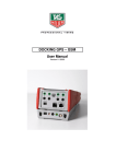
USER MANUAL
FOR
FIOA-0402-U-16
COPYRIGHT NOTICE
This manual is a publication of Renu Electronics Pvt. Ltd. and is provided for use by its customers only.
The contents of the manual are copyrighted by Renu Electronics; reproduction in whole or in part, for use
other than in support of Renu Electronics equipment, is prohibited without the specific written permission
of Renu Electronics.
SERVICE
If service is required then pack the unit in its original packaging container or, if unavailable, any suitable
rigid container. If a substitute container is used, surround the unit with shock absorbing material; damage
in shipment is not covered by the warranty. Include a letter with the unit describing the difficulty and
Hardware Revision and Software Version. Send to the following address:
Renu Electronics Pvt. Ltd.
Survey No. 2/6,
Baner Road,
Pune-411045
All returns will be tested to verify customer claims of noncompliance with the product warranty. Improper
return packaging, which makes verification impossible, will void the warranty. If noncompliance is verified
and is not due to customer abuse or the other exceptions described with product warranty, Renu
Electronics will, at its option, repair or replace the Product returned to it, freight prepaid, which fail to
comply with the foregoing warranty, provided REPL is notified of such noncompliance within the one-year
warranty period.
ASSISTANCE
This manual is designed to provide the necessary information for trouble-free installation and operation of
your new FIOA Series. However, if you need assistance, please call Renu Electronics Pvt. Ltd. at 91-2027292840 or visit our web site at www.renuelectronics.com
MANUAL REVISION
If you contact us in reference to this manual, please include the following document number
Name
:
User Manual For FIOA-0402-U-16
Part Number
:
URML414
Document
:
UMAN\FIOA-0402-U-16\0508
Revision
:
0.00
Revision Number
Document Number
Date
Description
Rev 0.00
UMAN\FIOA-0402-U-16\0508
08-05-2008
First Release
Contents
CH-1 INTRODUCTION
1.1
1.2
1.3
1.4
Purpose of this Manual
Introduction to FIOA-0402-U-16
Specifications:
Power Requirement:
CH-2 HARDWARE
2.1
2.2
2.3
2.4
Dimensional details and mounting instructions
Communication Port
Communication parameters and Modbus tag definitions:
Configuration:
CH-3 GETTING STARTED
3.1
3.1.1
3.1.2
3.1.3
3.2
3.3
3.3.1
3.3.2
3.4
Starting Prizm32 software:
Installing Prizm32 Software
Steps for starting Prizm32 Software
Uninstalling Prizm32 Software
Configuration of the unit:
Configuration Downloading procedure:
Prizm32 software configuration for downloading:
FIOA hardware configuration for downloading:
Upload:
CH-4 WIRING DIAGRAM
4.1
4.2
4.3
4.4
4.5
Analog Inputs:
Analog Outputs:
Multidropping Connection:
Data Output format for analog inputs:
Data entry format for analog outputs:
CH-5 CABLE DIAGRAM
5.1
5.2
5.3
5.4
IBM cable for downloading configuration:
Modbus master (PRIZM unit) to FIOA unit (2 Wire RS485):
Modbus master (PRIZM unit) to FIOA unit (RS232):
Modbus master (PRIZM unit) to FIOA unit (2 Wire RS485):
1
1
1
2
2
3
3
4
5
5
6
6
6
8
8
9
13
13
14
15
16
16
17
17
18
19
20
20
21
22
23
FIOA-0402-U-16 Manual
CH-1 INTRODUCTION
1.1
Purpose of this Manual
The intention of this Operation Manual is to provide a guide for Safe installation, Configuration and operation of FIOA unit.
Read this operation manual thoroughly before installing and operating the FIOA unit.
This document is based on information available at the time of its publication. While efforts have been
made to be accurate, the information in this document may not cover all the details or variations in hardware or software. Renu Electronics reserves the right to update information in this publication without prior
notice.
1.2
Introduction to FIOA-0402-U-16
FIOA 0402 U-16 is Analog Input Output Model having 4 Universal Analog inputs and 2 Analog outputs. The
Analog inputs can be Voltage ( 0-10V), Current (0 –20 mA, 4 – 20 mA), mV ( 0 –100 mV, 0 – 50 mV ), RTD
( PT 100 Alpha1 and Alpha2 constant ), Thermocouple ( B,R,S,E,J,K,N,T ). Each input channel can be
configured independently to work as any of the above type as per configuration made in the PRIZM
software. The Analog outputs can be Voltage ( 0 – 10 V) or Current ( 4 – 20 mA). Output channels also are
software configurable to current or voltage. The ADC & DAC resolution is 16 bit.
Unit supports standard Modbus RTU (slave) protocol for communicating with master device.
Internal circuitary (analog, digital and communication) is completely isolated from external power supply of
the unit. Also communication section is isolated from the internal circuit.
Renu Electronics Private Limited
Survey No. 2/6, Baner Road, Pune – 411 045
Maharashtra, INDIA
Tel: +91 20 2729 2840 Fax: +91 20 2729 2839
E-mail:
[email protected]
Website:
www.renuelectronics.com
1
FIOA-0402-U-16 Manual
1.3
1.4
Specifications:
1.
2.
3.
4.
Power Supply
Number of analog Inputs
Number of analog outputs
Analog Inputs
:
:
:
:
5.
6.
7.
Analog Outputs
Resolution
Communication Port
:
:
:
8.
9.
10.
11.
12.
13.
I/O Terminals
Operating Temperature
Storage Temperature
Humidity
Mounting
Dimensions (DIN rail)
:
:
:
:
:
:
24 VDC +/- 10%
4
2
Voltage (0-10V),
Current (0 –20 mA, 4 – 20 mA),
mV (0 –100 mV, 0 – 50 mV),
RTD (PT 100 Alpha1 and Alpha2 constant),
Thermocouple (Type: B, R, S, E, J, K, N, T)
Voltage ( 0 – 10 V) and Current ( 4 – 20 mA)
16 Bit
1. RJ45: RS232, 2-wire RS485, CMOS
2. Same 2 wire RS485 signals are available on
pluggable terminals
Pluggable terminals.
0OC to 50OC
-20OC to 80OC
10% to 90% (Non condensing)
DIN rail mounting
70 X 100 X 35 mm
Power Requirement:
FIOA is a 24VDC powered unit. Power should be applied on the PCB Terminal block on the unit. Power
rating is +24VDC +/- 10%; 2.5 Watts max.
Renu Electronics Private Limited
Survey No. 2/6, Baner Road, Pune – 411 045
Maharashtra, INDIA
Tel: +91 20 2729 2840 Fax: +91 20 2729 2839
E-mail:
[email protected]
Website:
www.renuelectronics.com
2
FIOA-0402-U-16 Manual
CH-2 HARDWARE
Dimensional details and mounting instructions
Following sketch shows dimensional details of FIOA with the mounting clamp.
70.
00
100.00
2.1
35
.00
Renu Electronics Private Limited
Survey No. 2/6, Baner Road, Pune – 411 045
Maharashtra, INDIA
Tel: +91 20 2729 2840 Fax: +91 20 2729 2839
E-mail:
[email protected]
Website:
www.renuelectronics.com
3
FIOA-0402-U-16 Manual
2.2
Communication Port
The RJ 45 COM Port has RS 232, RS 485 (two wire) and CMOS logic signals on its pins. This port can be
used to download the configuration in the unit from the PRIZM software as well as for communication with
any Modbus Master device. Same two wire RS 485 signals are provided on the terminal block for communication with Modbus Master Device.
Pinouts of RJ connector is as shown below:
4. DATA+ (A)
3. GND
2. RS232 RX
1. RS232 TX
5. DATA- (B)
6. Terminal resistor
7. NC
8. CMOS_TX
PIN1
PIN8
COMM Port
2 Wire RS485 connections on terminal block:
POWER
CS11
IN1+
AGND
I1CS21
COMM
ERR
FIOA
0402-U-16
GND
B
B
GND
A
A
B
TERM
REST
IN2+
AGND
I2-
COMM PORT
CS31
IN3+
AGND
I3-
A
TERM
REST
CS41
IN4+
GND
AGND
NC
B
I4-
TERM
REST
IO1
DC+
NC
AGND
NC
VO2
DC+
IO2
DC-
NC
NC
DC+
NC
A
VO1
120Ω
DC-
M
A
S
T
E
R
GND
DC-
+
-
24VDC
+/- 10%
EARTH
AGND
For using internal termination resistor (120 Ohm),
short “B” and “TERM REST”
Renu Electronics Private Limited
Survey No. 2/6, Baner Road, Pune – 411 045
Maharashtra, INDIA
Tel: +91 20 2729 2840 Fax: +91 20 2729 2839
E-mail:
[email protected]
Website:
www.renuelectronics.com
4
FIOA-0402-U-16 Manual
2.3
Communication parameters and Modbus tag definitions:
Unit supports standard Modbus RTU (slave) protocol for communicating with master device.
Driver:
Modbus RTU (slave)
Baud Rate:
9.6K, 19.2K, 57.6K OR 115.2K (Software Configurable)
Stop Bit:
1
No. of data bits: 8
Parity:
Odd, Even OR None (Software Configurable)
Station ID:
1 to 255 (Software Configurable)
The following dedicated modbus registers are assigned to analog inputs:
SR. No.
Analog Inputs
MODBUS Tag.
1.
INPUT 1
40001
2.
INPUT 2
40002
3.
INPUT 3
40003
4.
INPUT 4
40004
The following dedicated modbus registers are assigned to analog oututs:
SR. No.
2.4
Analog Outputs
MODBUS Tag.
1.
OUTPUT 1
40065
2.
OUTPUT 2
40066
Configuration:
FIOA 0402-U-16 requires PRIZM 32 software to configure analog input and outputs.
For downloading configuration use RJ COM Port of the unit.
Renu Electronics Private Limited
Survey No. 2/6, Baner Road, Pune – 411 045
Maharashtra, INDIA
Tel: +91 20 2729 2840 Fax: +91 20 2729 2839
E-mail:
[email protected]
Website:
www.renuelectronics.com
5
FIOA-0402-U-16 Manual
CH-3 GETTING STARTED
3.1
Starting Prizm32 software:
3.1.1
Installing Prizm32 Software
System requirements for installing Prizm32 on your PC:
Windows Version
Processor
Hard disk Space
Serial Mouse
RAM
:
:
:
:
:
Display resolution
Serial Port
:
:
Microsoft® Windows 2000 or higher
266 MHz Pentium® II or higher Pentium-compatible CPU
150 MB free memory space
Microsoft® mouse or compatible pointing device
At least 64 megabytes (MB) of RAM; more memory
generally improves responsiveness
800 X 600 with 24 bit true color
One Serial Port for Downloading Required
To install Prizm32 Software:
1. Open Microsoft® Windows.
2. Select Run and Pop up window appears. Type the path for installing the Setup.
This will install Prizm32 Setup Software.
3. When you click on OK, Welcome window appears on the screen. Click on Next.
Renu Electronics Private Limited
Survey No. 2/6, Baner Road, Pune – 411 045
Maharashtra, INDIA
Tel: +91 20 2729 2840 Fax: +91 20 2729 2839
E-mail:
[email protected]
Website:
www.renuelectronics.com
6
FIOA-0402-U-16 Manual
4. Enter user name and company name.
5. Select the destination folder where Setup will install the files.
Renu Electronics Private Limited
Survey No. 2/6, Baner Road, Pune – 411 045
Maharashtra, INDIA
Tel: +91 20 2729 2840 Fax: +91 20 2729 2839
E-mail:
[email protected]
Website:
www.renuelectronics.com
7
FIOA-0402-U-16 Manual
7. Installation starts. A dialog box indicating the status of progress of installation will display.
A screen is displayed to inform you when installation is completed.
This procedure installs Prizm32 Software in Start Menu (in selected folder).
3.1.2 Steps for starting Prizm32 Software
1. In Windows click the Start button.
2. Select Programs.
3. Select Prizm32.
4. Select New Application either from Tool station or from File Menu.
5. Select the product by clicking on picture of the product in the list.
6. Select model from model list.
7. Set configuration parameters for analog inputs, outputs and communication port settings.
3.1.3 Uninstalling Prizm32 Software
1. In Windows click the Start button.
2. Select Programs.
3. Select Prizm32.
4. Select Uninstall Prizm32.
Following screen will display. The screen will ask you for the confirmation for uninstalling Prizm32.
Renu Electronics Private Limited
Survey No. 2/6, Baner Road, Pune – 411 045
Maharashtra, INDIA
Tel: +91 20 2729 2840 Fax: +91 20 2729 2839
E-mail:
[email protected]
Website:
www.renuelectronics.com
8
FIOA-0402-U-16 Manual
7. When you click Yes button, it will uninstall Prizm configuration from your computer.
If you want to install Prizm32 again you have to follow the steps explained in section 3.3.1.
3.2
Configuration of the unit:
1. When you launch Prizm32 setup software and select FIOA unit as shown below:
Renu Electronics Private Limited
Survey No. 2/6, Baner Road, Pune – 411 045
Maharashtra, INDIA
Tel: +91 20 2729 2840 Fax: +91 20 2729 2839
E-mail:
[email protected]
Website:
www.renuelectronics.com
9
FIOA-0402-U-16 Manual
2. Select model from model list. Press “Next”. This will give you a analog I/O configuration wizard as
shown below:
Analog Input Configuration
Enable Analog Input: Check this check box to enable the selection of Analog Input channel.
Channel no: Channel number depends on the selection of FIOA model. Here user can configure 4 input
channels as selected FIOA model has 4 inputs.
Channel Type: Here selected model supports Universal inputs, so channel types are Thermocouple, mV,
mA, RTD and Voltage.
Each input channel can be configured independently as any of the input channel type.
Analog Output Configuration
Enable Analog Output: Check this check box to enable the selection of Analog Output channel.
Channel no: Channel number depends on the selection of FIOA model. Here user can configure 2 output
channels as selected FIOA model has 2 outputs.
Channel Type: Channel types are mA and Voltage.
Each output channel can be configured independently as any of the output channel type.
Renu Electronics Private Limited
Survey No. 2/6, Baner Road, Pune – 411 045
Maharashtra, INDIA
Tel: +91 20 2729 2840 Fax: +91 20 2729 2839
E-mail:
[email protected]
Website:
www.renuelectronics.com
10
FIOA-0402-U-16 Manual
3. The Analog Input and Output channel configuration is shown in the following screen:
4. If Thermocouple is selected as Channel type, then Thermocouple types are as shown below.
Renu Electronics Private Limited
Survey No. 2/6, Baner Road, Pune – 411 045
Maharashtra, INDIA
Tel: +91 20 2729 2840 Fax: +91 20 2729 2839
E-mail:
[email protected]
Website:
www.renuelectronics.com
11
FIOA-0402-U-16 Manual
5. To configure particular channel select Channel number, Channel type, channel subtype, normalization
factor (0 to 99) and click on Confirm button. The selected channel will be configured.
6. Normalization factor can be selected for each channel independently.
7. Follow the same procedure for configuring Analog Output channel.
8. Also define communication parameter settings. This is done by clicking the “Port Setting” button on the
wizard as shown below:
9. For communicating with master device; Baud rate and parity can select as shown below:
This completes the configuration of FIOA unit in Prizm32 software.
These configuration settings can be saved as “*.pzm” file so that we can use the same configuration next
time.
Renu Electronics Private Limited
Survey No. 2/6, Baner Road, Pune – 411 045
Maharashtra, INDIA
Tel: +91 20 2729 2840 Fax: +91 20 2729 2839
E-mail:
[email protected]
Website:
www.renuelectronics.com
12
FIOA-0402-U-16 Manual
3.3
Configuration Downloading procedure:
3.3.1
Prizm32 software configuration for downloading:
To download the configuration into the unit; follow the below given steps:
1. Press “Download” icon on the screen as shown below:
2. When user press “Download” icon from toolstation window; following screen will apprear:
Communication Port – This is used to define communication port for downloading. By default Com1 is
selected.
Click “Download” button to start download. By default; this task will complete application and firmware
downloading.
During download operation following error may be occur 1. Unit is not responding.
This error indicates that no communication has been etablished with unit. Please check cable connection
before you start downloading again.
2. Selected model is not matching with unit connected on IBM port.
This is product mismatch error. Please check you have defined correct model in application configuration.
Renu Electronics Private Limited
Survey No. 2/6, Baner Road, Pune – 411 045
Maharashtra, INDIA
Tel: +91 20 2729 2840 Fax: +91 20 2729 2839
E-mail:
[email protected]
Website:
www.renuelectronics.com
13
FIOA-0402-U-16 Manual
3.3.2
FIOA hardware configuration for downloading:
Follow the below given steps for downloading the application and firmware in the FIOA unit.
1. Remove communication cables from any master device.
2. Connect the IBM programming cable from PC to unit’s RJ45 COM Port.
(You may use RS 232 signals for communicating with PC.)
3. Power ON the FIOA unit.
4. Wait for 10 Seconds. The ERR led will glow. This means the unit is in Configuration Download mode.
5. Configure the input / output channel in the I/O configuration wizard of PRIZM software.
6. Press “Download” button in the Prizm32 software.
7. Prizm software will download the application and firmware in the unit.
8. After the firmware is downloaded connect the unit to Modbus master device.
#Note:
1. For downloading the configuration you must remove communication cables from any master device.
2. Once the unit is turned ‘ON’, ERR Led goes ‘ON’ only after 10 seconds.
3. Press Download only when ERR Led is ‘ON’.
4. If Download is pressed before turning ‘ON’ the ERR Led, you will have to restart the unit.
5. At power ‘ON’ if there is no PLC communication from the Master till 10 seconds, the unit will still enter
into the Configuration download mode, which is indicated by glowing ERR Led. But if any frame from
master arrives, unit will enter in to PLC communication mode switching ‘off’ the ERR Led.
6. ‘ERR’ LED turns OFF after 5 minutes of the power ON; even if there is no any download and no frame
from Modbus master
Renu Electronics Private Limited
Survey No. 2/6, Baner Road, Pune – 411 045
Maharashtra, INDIA
Tel: +91 20 2729 2840 Fax: +91 20 2729 2839
E-mail:
[email protected]
Website:
www.renuelectronics.com
14
FIOA-0402-U-16 Manual
3.4
Upload:
An application can be uploaded from the FIOA unit. To upload an application first select the appropriate
communication port for your computer by choosing “Communicate | Communication Port” menu option.
Attach a computer to FIOA cable. From the “Communicate” menu, click on the “Upload...” selection.
OR
In the Upload dialog, check the “Application” button and press the “Upload” button to begin uploading
the application.
Thus the application upload can be performed.
For uploading, hardware configuration is same as that for the downloading configuration of the unit.
Renu Electronics Private Limited
Survey No. 2/6, Baner Road, Pune – 411 045
Maharashtra, INDIA
Tel: +91 20 2729 2840 Fax: +91 20 2729 2839
E-mail:
[email protected]
Website:
www.renuelectronics.com
15
FIOA-0402-U-16 Manual
CH-4 WIRING DIAGRAM
4.1
Analog Inputs:
1. Current Input Connections:
+
mA
IN+
CS
Improper connection for current mode:
-
mA
AGND
CS
I-
+
-
IN+
AGND
I-
CURRENT
CURRENT
2. Voltage Input Connections:
+
V / mV
IN+
CS
AGND
I-
VOLTAGE & mV
3. RTD Input Connections:
RTD
IN+
CS
AGND
I-
3 WIRE RTD
4. Thermocouple Input Connections:
+
TC
IN+
CS
AGND
I-
THERMOCOUPLE
Renu Electronics Private Limited
Survey No. 2/6, Baner Road, Pune – 411 045
Maharashtra, INDIA
Tel: +91 20 2729 2840 Fax: +91 20 2729 2839
E-mail:
[email protected]
Website:
www.renuelectronics.com
16
FIOA-0402-U-16 Manual
4.2
Analog Outputs:
1. Current Output Connections:
Iout
VO
IO
AGND
2. Voltage Output Connections:
Vout
VO
4.3
IO
AGND
Multidropping Connection:
GND
FIOA Unit 1
B
A
M
A
S
T
E
R
FIOA Unit 2
FIOA Unit “n”
Note: Where “n” is upto 32. Connecting one
repeater can increase it to 64 and so on.
Renu Electronics Private Limited
Survey No. 2/6, Baner Road, Pune – 411 045
Maharashtra, INDIA
Tel: +91 20 2729 2840 Fax: +91 20 2729 2839
E-mail:
[email protected]
Website:
www.renuelectronics.com
17
FIOA-0402-U-16 Manual
4.4
Data Output format for analog inputs:
For
Voltage (0 to 10V)
Voltage Input
0V
For
0
2.5V
16384
5V
32768
7.5V
49152
10V
65535
Milivolt (0 to 100mV)
mV Input
0mV
For
Milivolt (0 to 50mV)
Count
mV Input
0
0mV
Count
0
25mV
16384
12.5mV
16384
50mV
32768
25mV
32768
75mV
49152
37.5mV
49152
100mV
65535
50mV
65535
Current (0 to 20mA)
Current Input
0mA
For
Count
current (4 to 20mA)
Count
Voltage Input
0
Count
4mA
0
5mA
16384
8mA
16384
10mA
32768
12mA
32768
15mA
49152
16mA
49152
20mA
65535
20mA
65535
RTD & Thermocouple
Output data will be in multiple of 10 of the actual temperature in degrees. It will be in the SIGNED
INTEGER format.
If temperature is 23.4 OC, data will be 234.
AND
If temperature is -57.1 OC, data will be -571.
#Note: Selecting unsigned integer format at Modbus master will give wrong readings for the negative
temperature range.
For Example:
Renu Electronics Private Limited
Survey No. 2/6, Baner Road, Pune – 411 045
Maharashtra, INDIA
Tel: +91 20 2729 2840 Fax: +91 20 2729 2839
E-mail:
[email protected]
Website:
www.renuelectronics.com
18
FIOA-0402-U-16 Manual
4.5
Data entry format for analog outputs:
For Analog output, enter the digital count for respective output register and observe the current & voltage
output on multimeter. It should be as per following table.
1. For Current (4 to 20 mA)
2. For Voltage (0 to 10 V)
Entered count
Current output
Entered count
0
Voltage output
0
4mA
0V
16384
8mA
16384
2.5V
32768
12mA
32768
5V
49152
16mA
49152
7.5V
65535
20mA
65535
10V
Renu Electronics Private Limited
Survey No. 2/6, Baner Road, Pune – 411 045
Maharashtra, INDIA
Tel: +91 20 2729 2840 Fax: +91 20 2729 2839
E-mail:
[email protected]
Website:
www.renuelectronics.com
19
FIOA-0402-U-16 Manual
CH-5 CABLE DIAGRAM
IBM cable for downloading configuration:
FIOA UNIT SIDE
PC SIDE
2 mtr.
IBM
5.1
DB9 FEMALE
(RS232)
SIGNALS
RJ45 CONNECTOR
(RS232)
Shield Wire
Pin #
Pin #
SIGNALS
1
1
TXD
RXD
2
2
RXD
TXD
3
3
SG
4
4
5
5
6
6
7
7
8
8
SG
9
Shield Wire
DB9 FEMALE PINOUTS
RJ45 CONNECTOR PINOUTS
R.H.S. VIEW
FRONT VIEW
9
Pin 1
(Left side)
5
Pin 8
(Right side)
6
1
Cable insert end
Cable insert end
Renu Electronics Private Limited
Survey No. 2/6, Baner Road, Pune – 411 045
Maharashtra, INDIA
Tel: +91 20 2729 2840 Fax: +91 20 2729 2839
E-mail:
[email protected]
Website:
www.renuelectronics.com
20
FIOA-0402-U-16 Manual
Modbus master (PRIZM unit) to FIOA unit (2 Wire RS485):
FIOA UNIT SIDE
PRIZM SIDE
2 mtr.
PLC
5.2
DB9 MALE
(RS485)
RJ45 CONNECTOR
(RS485)
Shield Wire
SIGNALS
Pin #
Pin #
TX+
1
1
A
2
SIGNALS
2
3
3
SG
RX+
4
4
A
SG
5
5
B
6
6
7
7
B
TX-
8
RX-
9
8
Shield Wire
DB9 MALE PINOUTS
RJ45 CONNECTOR PINOUTS
R.H.S. VIEW
FRONT VIEW
6
Pin 1
(Left side)
1
Pin 8
(Right side)
9
5
Cable insert end
Cable insert end
Renu Electronics Private Limited
Survey No. 2/6, Baner Road, Pune – 411 045
Maharashtra, INDIA
Tel: +91 20 2729 2840 Fax: +91 20 2729 2839
E-mail:
[email protected]
Website:
www.renuelectronics.com
21
FIOA-0402-U-16 Manual
Modbus master (PRIZM unit) to FIOA unit (RS232):
FIOA UNIT SIDE
PRIZM SIDE
2 mtr.
PLC
5.3
DB9 MALE
(RS232)
SIGNALS
RJ45 CONNECTOR
(RS232)
Shield Wire
Pin #
Pin #
SIGNALS
1
1
TXD
TXD
2
2
RXD
RXD
3
3
SG
4
4
5
5
6
6
7
7
8
8
SG
9
Shield Wire
DB9 MALE PINOUTS
RJ45 CONNECTOR PINOUTS
R.H.S. VIEW
FRONT VIEW
6
Pin 1
(Left side)
1
Pin 8
(Right side)
9
5
Cable insert end
Cable insert end
Renu Electronics Private Limited
Survey No. 2/6, Baner Road, Pune – 411 045
Maharashtra, INDIA
Tel: +91 20 2729 2840 Fax: +91 20 2729 2839
E-mail:
[email protected]
Website:
www.renuelectronics.com
22
FIOA-0402-U-16 Manual
5.4
Modbus master (PRIZM unit) to FIOA unit (2 Wire RS485):
POWER
COMM
CS11
ERR
IN1+
AGND
I1-
FIOA SIDE
CS21
FIOA
0402-U-16
IN2+
AGND
PRIZM SIDE
CS31
B
AGND
IN3+
I3-
A
CS41
TERM
REST
PLC
COMM PORT
I2-
GND
IN4+
AGND
NC
I4-
NC
VO1
DC+
AGND
DC-
VO2
GND
B
A
TERM
REST
IO1
NC
NC
DC+
IO2
DC-
AGND
WIRE OUTS
SIGNAL FROM PLC
SIGNALS
Pin #
RX+
YELLOW
TX+
GREEN
SG
BLACK
RX-
WHITE
TX-
BLUE
Shield Wire
Signals
A
SG
B
DB9 MALE PINOUTS
Shield Wire
1
5
6
9
Renu Electronics Private Limited
Survey No. 2/6, Baner Road, Pune – 411 045
Maharashtra, INDIA
Tel: +91 20 2729 2840 Fax: +91 20 2729 2839
E-mail:
[email protected]
Website:
www.renuelectronics.com
23