1
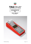
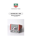
______________________________
PROFESSIONAL TIMING
DOCKING GPS – GSM
User Manual
Version 11/2009
1. General
•
•
•
The GPS Docking is equipped with a Li-Ion accumulator ensuring exceptional autonomy for the
Chronoprinter 540, even at very low temperatures (-20°C / -4° F).
A satellite detection module « GPS » ensures the automatic Time of Day synchronization and
precision control.
A GSM communication modem allows wireless connection between two CP540’s through the mobile
telephone network.
Power
Reset
Input
« Master Slave »
System A
•
Output
Top Minute
Antenna GPS
Connector
Antenna GSM
Connector
Output
« Master Slave »
System A
Charge LED
RESET button - in case of a problem with the Docking. To RESET, press the mini contact located
under the identification plate of the Docking.
Use a small blunt instrument to gently depress.
2. Important recommendation
•
•
•
•
•
•
•
To guarantee the security of your timekeeping, it is necessary to use your CP 540 with the internal
batteries in a charged state
Do not forget to charge the Docking before its use (see « How to charge the Docking »)
If the system is not used for several days, we recommend that you disconnect the Docking from the
Chronoprinter, and remove the batteries from the CP 540.
Do not forget to replace the « red blanking plug into the DOCKING » on the CP 540 to protect its
connector.
Protect the Docking with its original packing.
We recommend you to use the synchronization by GPS between two CP 540, which are
communicating Modem to Modem. The precision is thus guaranteed for your timing.
If you do not wish to use the Synchronization by GPS, please be sure to input the same date and time
on both systems before synchronizing them.
IMPORTANT
It is essential to update the software inside the CP 540 + Docking before initial use.
You will find the software version on our internet site (www.tagheuer-timing.com).
3. Docking connection
•
•
•
Remove the « DOCKING red blanking plug » from the CP 540 which gives access to the docking
connector.
Place the « DOCKING red blanking plug » on the Docking at the reserved position under the female
connector.
Place the CP 540 on the DOCKING and press firmly to ensure a good connection.
4. How to Use GPS
•
Carefully connect the GPS antenna cable in the socket (21).
The GPS antenna must be installed in a clear open place (outdoor) with an unobstructed view of the
sky in order to correctly receive the satellite signals generated by the GPS system.
•
Menu GPS (ON/OFF)
o Select GPS ON and confirm
o Select the time difference between GMT time and your time zone (ex GMT – 2, in the west of
GMT or GMT + 2 in the east of GMT).
o Validate your choice (this information is stored in memory).
o The display shows initially GPS Searching, then GPS Active as soon as it locates several
satellites.
o GPS Searching is also printed with the indication GPS UTC Delta = 15 sec. Then GPS
ready for Synchro.
o Validate 2 times under GSP to make the Synchro (mode Synchro)
The synchronization of Time of the Day with the correct date is automatically made.
REMARK
UTC TIME
The time provided by the satellites is GPS (terrestrial hours) of a certain number of seconds
(15 seconds since January 2009).
This information is transmitted by satellites every 12,5 mins.
It remains in the GPS almanac, this allows fast synchronization.
WARNING
When you remove the GPS antenna connector, hold the connector firmly. Never remove or hold
by the cable.
5. Remarks on GPS
► If GPS signal is Lost (poor positioning of the antenna), the printer indicates:
Synchro GPS lost
The time of day
The display time of day will flicker along with GPS LOST.
If the GPS signal is synchronized again, the printer indicates (repositioning of the antenna)
GPS Active
Synchro GPS found
Time of the day
DEV 3.0 µsec (for example)
Remark:
Automatic resynchronization of the time base of the CP 540 (temporary loss of GPS signal) is
acceptable in conditions where the drift of the time does not exceed 100 µsec (1/10'000 of a
second).
In case of resynchronization, the drift (DEV) is always printed.
If the drift value is over 100 µsec, the base time of the CP 540 is the reference for the rest of the
time keeping. The GPS can be switched OFF.
► If the Docking is disconnected the printers indicates:
Docking disconnected
Synchro GPS lost
Time of the day
When the Docking is reconnected the printer indicates
Docking Connected with its serial number and Software version
GPS Searching with GPS UTC Delta = 15sec
GPS Active
Synchro GPS founded
Time of the Day
DEV 2.4 µsec (for example)
6. How to use GSM
ATTENTION
The SIM Card should not have PIN number. Please disable any SIM PINs via your SIM
provider instructions.
6.1. General
•
•
•
•
•
Fit the GSM antenna to its connector.
Switch ON the CP 540 by pressing the Key ON for 5 seconds
The LCD display shows :
o Docking with 4 arrows directed to the top (arrow outgoing). These arrows show the status of
the 4 Data communication outputs (via RS232 or GSM).
o Charge status of the Docking (ex 85%) or Power supply presence
o GPS OFF
o GSM OFF
The incoming message of the CP 540 is printed with indication «Docking connected », its serial
number and software version.
Validate (OK) by pressing on ENTER (◄┘).
The Docking menu shows
o Status (of the Docking)
o GPS (ON/OFF)
o GSM (ON/OFF)
If the GPS is used for the Synchronization, please refer to the chapter « how to use GPS »
If the Synchro with GPS is not used, the display shows « Mode Synchro », select Manual or External.
Synchronize both CP 540 with the same date and time.
•
As soon the Synchro is done, come back to Docking GSM (ON/OFF)
o Select GSM ON and validate
o The LCD shows the Input E1 to E4 Status with 4 arrows.
These arrows indicate the direction of data – either transmit or receive of the timing
information from one Chronoprinter 540 to another. The status of each input can be
modified by pressing the respective E1 – E4.
It is possible to receive at the Start the Finish Time and at the Finish, the Start times.
Both CP 540’s will receive all information to edit results and ranking.
Example with one CP 540 at the start and another at the Finish:
Timing Mode: NET TIME
CP 540 at the Start:
-
With E1, program an outgoing arrow ( ) to transmit the times of the Start to
the Finish.
With E2 and E3, program «
», because these are used to transmit or
receive data for sector timing etc.
With E4, program the entering arrow (
) to receive the arrival time.
CP 540 at the finish:
-
With E1, program an entering arrow ( ) to receive the Start times to the
Finish.
With E2 and E3, program «
», because these are used to transmit or
receive data for sector timing etc
With E4, program the outgoing arrow (
) to transmit the Finish time.
Once the module GSM is enabled, the display shows “GSM Ready”
o Validate (OK) by pressing on ENTER (◄┘).
6.2. Mode CDS (Circuit Switched Data)
The Circuit Switched Data (CSD) is the original form for data transmission developed for the Ime
division multiple access – based mobile phone systems like Global System for Mobile communications
(GSM)
o
o
o
o
o
o
o
o
o
Select the mode CDS and valid by pressing on ENTER (◄┘).
LCD shows Modulation
> V.32 (related to the analog networks)
► V.110 (related to the numerical networks)
Select V.110 (the more popular choice for communicating Modem to Modem).
GSM Ready and Modem Setting V.110 are printed
Choose Modem on the CP540 which calls the other CP540. Validate
Compose the phone number of the second CP 540, and validate.
Call Modem is printed on the « caller » CP 540.
Income Call is printed on the « called » CP 540.
Connection Established is printed on both CP 540’s, when the bidirectional
communication is established.
ATTENTION
The GSM connection can sometimes be difficult to establish. If the connection Start – Finish is
not established after 3 or 4 automatic calls, you can try to call the Start from the Finish, or switch
GSM OFF and then ON again on both systems.
There also exists on the market GSM antennas to ensure better communication.
When the communication is established, the cost is the same as normal handy standard
communication. This communication could be expensive in certain cases.
But, this communication offer you the possibility to work in real time (no delay due to the
communication, as you have with GPRS communication).
The main menu has the indication « DOCKING ».
It is possible to check the status at anytime (or battery status, GPS Active or number of satellites).
Important information
-
-
In the menu Docking, you will have access to GSM Hang Up. Use this option to close the
communication if you don’t need the communication for a long period (to save cost of
communications).
To restore the communication, use Modem on one of the systems.
In case of temporary lost GSM communication (or poor reception of signal), the « caller »
system will try to automatically to re-establish the communication. All timing information not
already transferred will be automatically stored and then transmitted when the connection is
re- established.
6.3. GPRS mode
The GPRS (General Packet Radio Service) is an extension of GSM protocol. This mode is more
adapted to the data transmission. The resources are allowed only when data is being transmitted,
contrary to the CDS mode where the communication is allowed constantly.
o
o
o
Set the communication parameters via RS232
Use the program “CP540 GPRS setting” (available on www.tagheuer-timing.com)
Set the Access Point, User ID, Password (if necessary), Domaine Name or IP address,
sure as port number.
For countries and operator the access point name is different. It is necessary to contact
your operator to get this information (or via internet).
This information should be saved to the Docking. It is not necessary to do this setting each
time as this information is stored.
Important: if you download a new software version, you will lose your settings.
For further information, please read the user’s manual “Server GPRS” available on
www.tagheuer-timing.com.
o
o
o
Select GPRS mode and validate by pressing on ENTER (◄┘).
As soon the docking is connected to your server, the printer will print “CONNECTION
ETABLISHED”
You GPRS connection is now ready to transmit times.
ATTENTION
The GPRS mode could take a couple of 1/10 seconds to transmit data.
NOTE
It is very important to read carefully the user’s manual of «TAG Heuer CP540 Server »
7. How to insert the SIM Card in the Docking
Use a Standard SIM Card (annual subscription) or with pre-payment.
To guarantee a bidirectional communication between CP 540’s, it is necessary to have two GSM Docking
stations, with SIM cards with a different telephone number.
Proceed to the following steps:
- Unscrew the 5 screws on the back of the Docking with a Phillips screwdriver N° 1.
- Carefully, remove the upper cover.
- Place the SIM Card from the top into the support, with the 45° angle at Top Left. Push the card gently
downwards.
-
Replace the upper cover, return the Docking and secure gently the 5 screws while checking that the
two parts are well positioned. Press on the top of the Docking when you tighten the screws.
WARNING
Tighten all the screw slightly then, while being conscious that you screw in plastic, tighten a little
more, without over tightening (risk of damage to the plastic).
We advise against the repeated opening and the closing of the Docking.
For the Pre-paid SIM Card, it is generally possible to top-up the SIM Card via the internet.
Choose a telecom company with wider broadcast coverage.
It is also possible to have a SIM Card with an annual subscription.
Do not forget to write your phone number on the back of the Docking, even if it is memorized in
the Chronoprinter 540.
Do not cross CP 540 and Docking !
Suggestion: place a small green sticker on the CP 540 and Docking for the Start and red for the
Finish.
8. Information
⇒ The GSM – GPS Docking has « banana » output connector to provide a signal TOP-MINUTE which is
useful to synchronize other timing systems.
⇒ If the GPS is used only for the CP 540, it is recommended to wait 4 – 5 mins before to switching it
OFF (« memorize » the GPS precision)
⇒ The GSM – GPS Docking has an Input / output « Master / Slave ». This mode of synchronization
between several CP 540’s is very useful for the timekeeper, to guarantee absolute precision between
different systems.
For example: System A (Master) and the back-up system B (Slave).
Connect the CP 540 A « Master » to CP 540 B « Slave » with the special cable HL540-11.
The CP 540 A is synchronized with the Time of Day, manually or with GPS.
The CP 540 B is automatically synchronized by the CP 540 A by choosing Master/Slave in the
Synchro Menu.
If the Main system A is disconnected or communication fails, the back-up system B will operate with its
own time of base.
The Drift (DEV) described later « Synchronization by GPS » is also into the mode. Thus, if the Main
System A is again operational, it will take its main function as Master if the Drift is lower that 100 µsec.
All information is of course printed.
9. How to charge the Docking accumulator
•
•
•
•
•
The Docking can be charged seperately or connected to a CP 540.
Charge the docking with the power supply HL 540-1 from the CP 540
Connect the power supply to the POWER connector of the Docking (connector 3 poles).
The LED located at the bottom of the Docking allows you to see the charging status.
o LED is red during the charge (6 hours for a complete charge)
o LED is green when the docking is fully charged
When the CP 540 is used with the Docking, the external power supply should be connected to the CP
540.
WARNING
The Docking should be not charged in temperatures lower than 0°C / 32°F.
Remarks:
The charging status of the Docking is displayed on the CP540 LCD if charged together.
If the Docking is too discharged, the batteries of the CP 540 will power the system. If the power is too
low, the Time on the LCD will flicker and the printer will print « Low battery » before to switching OFF
automatically.
When the charge indicator of the Docking shows 50% on the LCD (Docking Menu), you still have at least
4 hours of autonomy.
10. Technical specification
General
o
o
o
o
Accumulator
o
o
o
Operating condition
External power supply
Top minute output
Connector IN / OUT
-20°C to +60°C
12Vdc
(optocoupler)
for Master / Slave (2 x RJ13)
Type
Charging condition
Charging current
7.4V Li-Po 2700mAh
0° to +40°C
500mA (~5.5 hours)
GPS
o
o
o
o
Precision
Current consumption when activated
12 channels, continuous tracking receiver.
Connector for external antenna
+/- 50 n seconds (+/- 50 x 10-9 sec)
30 mA (when GPS is actived)
o
o
Quad-band
EGSM 850 / 900 / 1800 / 1900 MHz
Output Power
• Class 4 (2W) from 850 / 900 MHz
• Class 1 (1W) from 1800 / 1900 MHz
Data transmission
• CDS, 9600 Bds, V.92, V.110 (Modem)
• GPRS Class 10
Standby consumption : 63 mA
Average consumption in Modem Mode: 197 mA
Connector for external antenna
GSM
o
o
o
o
TAG Heuer
PROFESSIONAL TIMING
6A Louis-Joseph Chevrolet
2300 la Chaux-de-Fonds
Switzerland
Tel : 032 919 8000
Fax : 032 919 9026
E-mail: [email protected]
Http: //www.tagheuer-timing.com