1
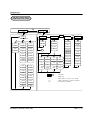
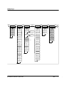
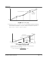
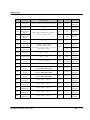
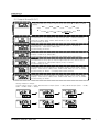
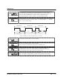
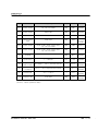
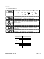
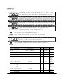
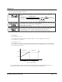
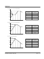
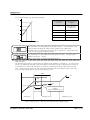
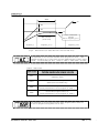
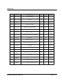
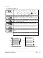
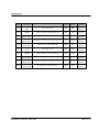
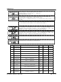
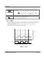
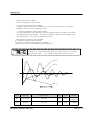
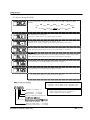
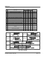
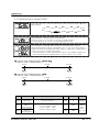
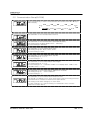
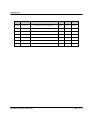
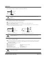
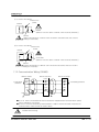
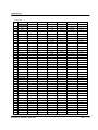
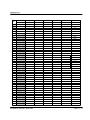
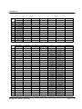
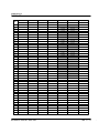
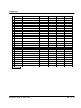
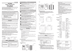
Instruction Manual
Contents
1. Safety Guide
3
2. Control Keys and Display
5
3. Parameter Map
6
4. Flow of Operating Display
8
5. Setting Up Parameter in each Group
9
5.1 Input Group(G.IN)
9
5.2 Output Group(G.OUT)
13
5.3 Control Group(G.CTL)
16
5.4 Program Group(G.PROG)
18
5.5 Digital Output Group(G.DO)
24
5.6 Inner Signal Group(G.IS)
25
5.7 PID Group(G.PID)
27
5.8 Auto Tunning Group(G.AT)
29
5.9 Alarm Group(G.ALM)
31
5.10 Retransmission Group(G.RET)
34
5.11 Communication Group(G.COM)
35
6. Display Error and Correction
37
7. Installation
38
7.1 Dimension and Panel Cutout
38
7.2 How to install Mount
42
7.3 Power Cable Specification
43
7.4 Terminal Specification
43
7.5 Terminal Arrangement and External Wiring
44
7.6 Grounding and Power Cable Connection
48
7.7 Analog Input Connection
48
7.8 Analog Output Connection
49
7.9 External Contact Output Connection(RELAY)
50
7.10 External Contact Input Connection(DI)
50
7.11 Use an Auxiliary Relay
50
7.12 Communication Wiring(RS485)
51
Attach. Table of D-Register
52
Table 1 : Type of Input Sensor
9
Table 2 : DI Operation
16
Table 3 : Link Code
21
Table 4 : DO Setting Type
Table 5 : Type of Alarm
24
32
Fig 1 : Example of Piece Bias
11
Fig 2 : Example of Piece Bias Formula
11
Fig 3 : Example of Control Output (CT = 10 sec)
14
Fig 4 : SSP START
18
Fig 5 : Wait Function-Wait Function Release Within Waiting Time
20
Fig 6 : Wait Function /PV input data can’t enter the wait zone
21
Fig 7 : Example of Inner Signal Zone
25
Fig 8 : Overshoot Suppressing by Fuzzy Function
27
Fig 9 : AUTO TUNING
29
Fig 10 : AT GAIN
30
Fig 11 : Alarm Operation
32
The following safety symbols are used in this manual
(A) If this symbol is marked on the product, the operator must investigate the explanation given in this
manual to protect injury or death to personnel or damage to instrument.
(1) For Production : it should be marked when operator must refer the explanation in the
manual to avoid loss of life or damage to instrument.
(2) For Instruction Manual : it marks to avoid operator’s loss of life and injury that may result
comes from Electric Shock.
(B) Functional earth terminal
Equipment protected by double or reinforced insulation
It marks the terminal must be connected to Ground prior to operating the equipment.
(C) It marks additional Information on the operation and features of the product.
(D) It marks for further information on the current topic and pages
(1) This Manual should be passed on the end User and keep a suitable place for operator to
study and check the function of the product.
(2) Operator should carefully study, understand how to operate this product before
(3) This manual is describing the functions of the product. We, Samwontech, does not warrant
that the functions will suit a particular purpose.
(4) Under absolutely no circumstance may the contents of this manual in part or in whole be
transcribed or copied without permission.
(5) All contents of this manual has been made to ensure accuracy in the preparation, However,
should any errors or omissions come to the attention of the user, feel free to contact our
sales representatives or our sales office
(1) In order to protect this product and the system controlled by it against damage and ensure
its safe use, make certain that all of the safety instructions and precautions in this manual
are strictly adhered to.
(2) We, Samwontech, are not guarantee safety if the products are not handled according to
this instruction manuals
(3) If separate protection or safety circuits are to be installed for this product or the system
which is controlled by this product, ensure that such circuits are installed external to the
product.
(4) Don’t try to make modifications or additions internal to the product. It may becomes
electric shock, burn or out of order.
(5) In case of replacement parts or consumables of the product, must call to our sales office.
(6) Protect this product from moisture. It may becomes out of order.
(7) Protect any kind of shock and vibration to the product. It may becomes product defects
and out of order
(1) Samwontech co. Ltd does not make any warranties regarding the product except Warranty
conditions those mentioned in this manual.
(2) We assumes no liability to any party for any loss or damage, direct or indirect, caused by
the use or any unpredictable defect of the product.
(1) The guaranteed period of the production quality assurance is (1) one year after end user
buy it and it will be free to fix defected product under regular usage described
by this manual.
(2) It will be charged to fix defected product after warranty period. This charge will announced
by our actual cost to be calculated during the fixing time.
(3) It will be charging even if within warranty period as following events.
(3.1) Defect by operator and user’s default.(forget password, production initialize)
(3.2) Natural disaster.(fire, water flow etc)
(3.3) Additional shift after 1st installed.
(3.4) Improperly repaired, or altered, modified in anyway.
(3.5) Power failure in unstable power condition.
(4) Feel free to contact our sales office whenever it need to make A/S.
(1) Be sure to operate the controller installed on a panel to prevent electric shock.
(2) To install the controller, do select a location where;
■ No one may accidentally touch terminal.
■ Mechanical vibrations are minimal.
■ No corrosive gas is prevent.
■ Temperature fluctuation is minimal.
■ Temperature can be maintained. (50 ℃ below / 10 ℃ over)
■ No direct heat radiation is present.
■ No magnetic disturbances are caused
■ No water is splashed.
■ No flammable materials are around.
■ No wind blows. (prevent Dust with salt)
■ No ultraviolet rays are present.
■ Pollution Degree 2
■ Installation Category II
■ Do not block openings
■ If the equipment is used in a manner not specified by the manufacturer,
the protection provided by the equipment may be impaired.
■ A switch or circuit-breaker acting as the disconnect device shall be included in the
application or the building installation
■ Keep the input circuit wiring as far as possible away from power and ground circuit.
■ Keep the controllers in 10℃ ~ 50℃/ 20 % ~ 90 % RH,
Warming up needed to use controller when temperature is below 10℃ in advance.
■ Do not mount front panel facing downward.
■ To prevent electric shock, be sure to turn off and the source circuit breaker before wiring.
■ The power consumptions are 100-240VAC, 50/60Hz, 10VAmax and operate without power
switching in advance.
■ No work in wet hands ( it caused electric shock)
■ Follow operation by precaution in the manual to avoid fire, electric shock, loss of life etc.
■ Requested to follow mounting and operation methods just indicated in this manual.
■ Refer the way of grounding connection, however, keep away for grounding to Gas pipe,
water pipe, lightening rod etc.
■ Be sure not to power connection before finishing of wiring between each contact point.
■ Not close and wrapping the heat hole in back case of controller.
⊙ Control Keys
KEY
Contents
SET/ENT
(ENTER)
- Used in switching between parameters or registering parameter settings.
- Pressing SET/ENT Key at least 3 sec. switches between an operating display
and an operating parameter setting display
▲/▼
(UP/DOWN)
◀ (SHIFT)
PROG1(P1)
PROG2(P2)
RESET(RST)
- Used to change the value of parameters.
- Used to move between GROUP and change SP value.
- Used when shifting position to modify value.
- Pressing to operation Program 1 ( pressing for 1 sec)
- Pressing to operation Program 2 ( pressing for 1 sec)
- Pressing when Pattern End( pressing for 1 sec),
and Program setting mode End.
⊙ LED Display
LED
EV1,2,3
OUT
AT
PRG1
PRG2
HOLD
Contents
-
Lights
Lights
Lights
Lights
Lights
Lights
on
on
on
on
on
on
during EVENT occurs.
when Control Output occurs.
when Auto-Tuning operates.
during operation of Program Pattern 1.
during operation of Program Pattern 2.
when operation of Program suspended.
▼▲
SET/ENT
SFT
SFT
SET/ENT
▼▲
PTNO
G.AT
SET/ENT
PTNO=0
PWD
G.PID
SET/ENT
PTNO=1
PTNO=2
TMU
1.LC
2.LC
STC
1.SSP
2.SSP
WZ
1.SP1
2.SP1
WTM
1.TM1
2.TM1
1.TS1
2.TS1
1.SP2
2.SP2
1.TM2
2.TM2
1.TS2
2.TS2
…
…
1.SPE
2.SPE
1.TME
2.TME
1.TSE
2.TSE
1.SPF
2.SPF
1.TMF
2.TMF
1.TSF
2.TSF
1.RPT
2.RPT
1.REN
2.REN
1.RST
2.RST
▼▲
G.CTL
SET/ENT
SET/ENT
G.IS
SET/ENT
AT
ARW
PE.TM
1.IST
AT-G
C.MOD
US1
1.ISB
FUZY
US2
1.ISH
PID
LOCK
1.ISL
DI.SL
1.ISD
OSTS
2.IST
DSP.H
2.ISB
DSP.L
2.ISH
U.PWD
2.ISL
INIT
2.ISD
B
1.P
2.P
3.P
4.P
1.I
2.I
3.I
4.I
1.D
2.D
3.D
4.D
1.MR
*
1.RP
2.MR
*
2.RP
3.MR
*
RHY
4.MR
*
RDV
: OPTION
*
**
***
****
:
:
:
:
when I=0
When type of OUT2, 3 is “Heat”
Option display for SP570, SP540
No Option in SP540
▼▲
▼▲
G.DO
SET/ENT
▼▲
G.IN
▼▲
G.OUT
SET/ENT
SET/ENT
DO1
IN-T
OUT1
DO2
IN-U
OUT2
DO3
IN.RH
DO4
IN.RL
OUT3
***
▼▲
G.ALM
SET/ENT
SET/ENT
▼
G.COM
SET/ENT
ALT1
RET
COM.P
HEAT
AL-1
RETH
BAUD
**
AL1.H
RETL
PRTY
HEAT
AL1.L
SBIT
A1DB
DLEN
A1DY
ADDR
ALT2
RP.TM
IN.DP
IN.SH
SUB1
IN.SL
SUB2
IN.FL
O.ACT
AL-2
D.FL
CT
AL2.H
BSL
OH
AL2.L
RSL
OL
A2DB
BSP1
PO
A2DY
BSP2
O.LED
ALT3
****
BSP3
AL-3
BS0
AL3.H
BS1
AL3.L
BS2
A3DB
BS3
A3DY
BS4
▼▲
G.RET
B
Set up time for unit, wait and
wait zone, Link, Time Signal and
each segment of Pattern.
*NOTE 1
ENT
SET/ENT 3 sec or
No Key 60 sec
▼ or ▲
*NOTE 2
ENT
SET/ENT
3 sec
The set up parameter setting up
is used to set setup parameters
(G.IN/G.OUT),which determine
the controller’s function and
must be set before starting
operation of the controller.
*NOTE 3
ENT
*NOTE 4
ENT
*NOTE 5
ENT
*NOTE 6
ENT
(*note
(*note
(*note
(*note
(*note
(*note
(*note
(*note
1:
2:
3:
4:
5:
6:
7:
8:
Display ‘STOP’ when operates stopping.)
Initial display after power on.)
Operation display for Output.)
Display segment number in process.)
Display balance time of segment in process.)
Display program running : STEP ON/OFF)
Display program running : HOLD ON/OFF)
Display ‘H.SP’/SP Value when operates hold during
SOAK zone : Changeable for SP Value)
(*note 9: Display ‘H.SP’/time when operates hold during
Soak zone : Changeable for Hold Time)
(*note 10: In case of registration for USER SCREEN 1)
(*note 11: in case of registration for USER SCREEN 2)
*NOTE 7
ENT
US1, US2 can be set up by operator
for modifying parameters and set up
in G.CTL refer to Table of D-Register
as attached in this manual
*NOTE 8
ENT
*NOTE 10
*NOTE 9
*NOTE 11
5.1 Input Group(G.IN)
Press SET/ENT Key to select input group after press ▲ or ▼ Key in Menu
display. (Refer to parameter Map in chapter 3.)
▲▼
▲▼
▲▼
▲▼
▲▼
G.AT ↔ G.PID ↔ PWD ↔ G.CTL ↔ G.IS ↔ G.DO
↕▲▼
▼↑
G.COM ↔ G.RET ↔ G.ALM ↔ G.OUT ↔
▲▼
▲▼
▲▼
▲▼
Change setting up parameters should be done for the first stage because it is
suspended initializing parameters in other group around.
The parameter to select type of temperature sensor and its initial setting is
type TC,K1.
Refer to following ‘Table of Input Sensor’ and select No shown in Table 1.
No.
1
2
3
4
5
6
7
8
9
10
11
12
13
14
15
16
17
18
19
20
21
22
23
24
TYPE
K1
K2
J
E
T
R
B
S
L
N
U
W
Platinel Ⅱ
C
PtA
PtB
PtC
JPtA
JPtB
0.4∼2.0V
1∼5V
0∼10V
-10∼20mV
0∼100mV
Temp.Range(℃) Temp.Range(°F)
-200∼1370
-300∼2500
-199.9∼999.9
0∼2300
-199.9∼999.9
-300∼2300
-199.9∼999.9
-300∼1800
-199.9∼400.0
-300∼750
0∼1700
32∼3100
0∼1800
32∼3300
0∼1700
32∼3100
-199.9∼900.0
-300∼1600
-200∼1300
-300∼2400
-199.9∼400.0
-300∼750
0∼2300
32∼4200
0∼1390
32∼2500
0~2320
32∼4200
-199.9∼850.0
-300∼1560
-199.9∼500.0 -199.9∼999.9
-19.99∼99.99
-4.0∼212.0
-199.9∼500.0 -199.9∼999.9
-150.0∼150.0 -199.9∼300.0
0.400∼2.000V
1∼5V
0∼10V
-10∼20mV
0∼100mV
Group
T/C
RTD
DCV
mV
DISP
TC.K1
TC.K2
TC.J
TC.E
TC.T
TC.R
TC.B
TC.S
TC.L
TC.N
TC.U
TC.W
TC.PL
TC.C
PTA
PTB
PTC
JPTA
JPTB
2V
5V
10V
20M
100M
The parameter to select type of temperature unit for ℃ or ℉.
Its initial selection is ℃ type.
Refer to Table 1 when change temperature unit.
The parameter to set High-Limit for input temperature measuring range.
The parameter to set Low-Limit for input temperature measuring range.
The parameter to set the position of decimal value in case that sensor type is
mV or V. The position if decimal value can change 0 ~ 3.
its initial set value is ‘1’.
The parameter to set High-Limit of input measuring scale in case that sensor
type is mV or V.
its initial value of ‘In.SH’ is ‘100.0’
The parameter to set Low-Limit of input measuring scale in case that sensor
type is mV or V.
its initial value of ‘In.SL’ is ‘0.0’
The parameter to set PV filter for stabilizing from electromagnetic noise etc.
it may effect violation of PV value. Its initial value of ‘In. FL’ is OFF and
can change 1 sec to 120 sec.
The parameter to set for decreasing when PV is unstable due to senstive
sensor response under normal control.
The parameter to set a direction of PV operation when sensor open. When set
value of BSL is ‘UP’, PV operation is for High-Limit of Input Sensor.
When set value of BSL is ‘DOWN’, PV operation is for Low-Limit of Input
Sensor. Its initial setting is ‘UP’ (* in case of mV, V input, initialize ‘OFF’ and
No checking Sensor-Open in 10V, 20mV, 100mV
The parameter to set whether using RJC or not in case that input sensor is
thermocouple. Its initial setting of ‘rSL’ is ‘ON’
The parameter to set range of Bias in PV value enabling Bias process.
Bias range can set Max 4. for further information, refer to Fig 1. and Fig 2.
..
.
The parameter to set Bias value of PV in Bias range.
For further information, refer to Fig 1. and Fig 2.
..
.
BS4
BS3
Actual Temperature
Temperature
after Bias
BS2
BS1
BS0
RL
BSP1
BSP2
BSP3
RH
Ex) There are +2℃ in 25℃, -1℃ in 50℃, +3℃ in 75℃ as temperature deviation in measuring
actual temperature in range from 0℃ to 100℃, and try to take a Piece Bias, each Bias set
value are shown as belows(RL=0℃, BSP1=25℃, BSP2=50℃, BSP3=75℃, RH=100℃)
BS0=0℃, BS1=-2℃, BS2=+1℃, BS3=-3℃, BS4=0℃
BS4=0
Temperature
after Piece Bias
BS3=50
BS2=10
Actual
Temperature
:Actual
600℃
P Temperature
after Bias
BS1=10
BS0=0
RL=0
BSP1=100
BSP2=500
BSP3=800
RH=1000
Temperature Bias Value = Temperature after Bias - Actual Temperature
Temperature in 600℃(P) after Bias
P = 600 + (600-BPS2) X
BS3 - BS2
BSP3 - BSP2
+ BS2
Sym
Parameter
Setting Range
Unit
Initial
Remark
IN-T
Input Type
Refer to Table 1 Type of Input Sensor
ABS
TC.K1
All time
indicate
IN-U
Display Unit
℃ / °F
ABS
℃
T/C, RTD
EU
1370
All time
indicate
EU
-200
All time
indicate
ABS
1
mV, V
100.0
All time
indicate
0.0
mV, V
Max. Value of
Measurement
Range
Min. Value of
Measurement
Range
Within DEF. Range refer to Table 1
however, INRH > INRL
IN.DP
Decimal Point
Position
0∼3
IN.SH
Max Value
of Input Scale
IN.SL
IN.RH
IN.RL
Min Value
of Input Scale
Within -1999∼9999
however, INSH > INSL
The Decimal Point Position is relay on
the value of IN.DP
ABS
IN.FL
PV Filter
OFF, 1∼120
sec
OFF
All time
indicate
D.FL
Display Filter
OFF, 1∼120
sec
OFF
All time
indicate
BSL
BOUT SEL
(note1)
OFF, UP, DOWN
ABS
UP
(DCV=OFF)
All time
indicate
RSL
RJC SEL
ON, OFF
ABS
ON
T/C
BSP1
Reference Bias
Point1
EU(0.0∼100.0%),
RL BSP1 BSP2 BSP3 RH
EU
EU(100.0%)
All time
indicate
BSP2
Reference Bias
Point2
EU(0.0∼100.0%),
RL BSP1 BSP2 BSP3 RH
EU
EU(100.0%)
All time
indicate
BSP3
Reference Bias
Point3
EU(0.0∼100.0%),
RL BSP1 BSP2 BSP3 RH
EU
EU(100.0%)
All time
indicate
BS0
Bias Value for
RL Point
EUS(-100.0∼100.0%)
EUS
0
All time
indicate
BS1
Bias Value for
BSP1 Point
EUS(-100.0∼100.0%)
EUS
0
All time
indicate
BS2
Bias Value for
BSP2 Point
EUS(-100.0∼100.0%)
EUS
0
All time
indicate
BS3
Bias Value for
BSP3 Point
EUS(-100.0∼100.0%)
EUS
0
All time
indicate
BS4
Bias Value for
RH Point
EUS(-100.0∼100.0%)
EUS
0
All time
indicate
(note 1) : S.OPN(Sensor-Open)=BOUT(Burn-Out)
5.2 Output Group(G.OUT)
Press SET/ENT Key to select Output Group after press ▲ or ▼ Key in Menu
display.
▲▼
▲▼
▲▼
▲▼
▲▼
G.AT ↔ G.PID ↔ PWD ↔ G.CTL ↔ G.IS ↔ G.DO
↕▲▼
▼↑
G.COM ↔ G.RET ↔ G.ALM ↔
↔ G.IN
▲▼
▲▼
▲▼
▲▼
The parameter to set operation of output control (OUT 1 :RELAY OUTPUT)
Value set in HEAT, ALM1, ALM2, ALM3, RUN, IS1, IS2, TS, PEND.
Its initial setting is ‘ALM1’
The parameter to set operation of output control (OUT 2 : 4~20mV or
Pulse Output). Value set in ‘HEAT, RET’.
Its initial setting is ‘HEAT’.
The parameter to set operation of output control (OUT 3: 4~20mV or Pulse
Output) Value set in ‘HEAT, RET’.
Its initial setting is ‘RET’. (* SP570/540 can display when option select)
The parameter to set a type of control output when OUT 2 or OUT 3 sets in
‘HEAT’. Value set in ‘SSR (Pulse Output), SCR ( 4~20mV)’.
Its initial setting is ‘SSR’.
The parameter to set the operation of Auxiliary Output Control (SUB 1: Relay
Output). Value sets in ‘HEAT, ALM1, ALM2, ALM3, RUN, IS1, IS2, TS, PEND’,
Its initial setting is ‘ALM2’. (* Display when option selects)
The parameter to set the operation of Auxiliary Output Control (SUB 2: Relay
Output). Value sets in ‘HEAT, ALM1, ALM2, ALM3, RUN, IS1, IS2, TS, PEND’.
Its initial setting is ‘ALM3’.
※ Setting example of Output :
Control Output (OUT2 → SSR), Retransmission Output (OUT3 → RET), RELAY Output (OUT1 → ALM1,
SUB1 → ALM2, SUB2 → ALM3)
The parameter to set Reverse or Forward operation of Control Output.
If ‘O.Act’ sets Reverse operation and PV value is lower the SP value, The
control output is ON(Relay) or increase control output(SSR,SCR)
If Forward operations, it works reverse. Its initial setting is ‘REV’.
The parameter to set one cycle time of control ON/OFF when control output
sets up Time-proportional control output. Its setting range is 1 ~ 1000 sec
and ‘2’ sec as initial setting.
Output=50%
5 Sec
5 Sec
CT=10 Sec
Output=70%
7 Sec
Output=30%
3 Sec 3 Sec
CT=10 Sec
7 Sec
CT=10 Sec
(Fig 3 : Example of Control Output in CT = 10 Sec)
To set High-Limited value of Control Output.
To set Low-Limited Value of Control Output.
Control Output is limited within High and Low limited value.
The parameter to set Preset Output value for emergency output.
It makes output value in ‘Po’ after stopping control output calculated
by PID algorithm when stop or A/D Error, Sensor open.
The parameter to set operation of MV OUT LAMP.
SSR : MV LAMP is blinking within CT when SSR or Relay control output.
SCR : MV LAMP is blingking irrespective of CT when SCR control output.
Sym
Parameter
Setting Range
Unit
Initial
Remark
OUT1
Select Output
HEAT, ALM1, ALM2, ALM3, RUN,
IS1, IS2, TS, PEND
ABS
ALM1
All time
indicate
OUT2
Select Output
HEAT, RET
ABS
HEAT
All time
indicate
OUT3
Select Output
HEAT, RET
ABS
RET
(note)1
HEAT
Select Ouput
Type
SSR, SCR
ABS
SSR
When OUT
2, 3 is in
‘HEAT’
SUB1
Select Output
HEAT, ALM1, ALM2, ALM3, RUN,
IS1, IS2, TS, PEND
ABS
ALM2
Option시
SUB2
Select Output
HEAT, ALM1, ALM2, ALM3, RUN,
IS1, IS2, TS, PEND
ABS
ALM3
(note)2
O.ACT
Reverse and
Forward
REV, FWD
ABS
REV
All time
indicate
CT
Cycle Time 1
1 ∼ 300 sec
sec
2 sec
All time
indicate
OH
High-Limit
Value of Output
OL+1Digit ∼ 105.0% However,OH>OL
%
100.0%
All time
indicate
OL
Low-Limit Value
of Output
-5.0% ∼ OH-1Digit However,OH>OL
%
0%
All time
indicate
PO
Preset Out1
-5.0 ∼ 105.0%
%
0.0%
All time
indicate
O.LED
OUTPUT LED
SCR, SSR
ABS
SSR
All time
indicate
(*note 1) : All time indicate (SP570, 540 is Option)
(*note 2) : Option (SP540 is SKIP)
5.3 Control Group(G.CTL)
Press ‘SET/ENT Key to select Control Group after press ▼ or ▲ Key in Menu
display.
▲▼
▲▼
▲▼
▲▼
▲▼
G.AT ↔ G.PID ↔ PWD ↔
↔ G.IS ↔ G.DO
↕▲▼
▼↑
G.COM ↔ G.RET ↔ G.ALM ↔ G.OUT ↔ G.IN
▲▼
▲▼
▲▼
▲▼
It makes a Output during the setting time when sets in Pattern End.
(it makes a output when PEND sets in G.OUT)
its initial setting is ‘15’ sec. It operates in second unit counting.
The parameter to set User Screen for display, confirmation and common use of
parameter. In order to register US1, 2, refer to the parameter number in
‘Table of D-Register.
Its initial setting of US1, 2 is ‘OFF’.
The parameter to set parameter display for common using or checking.
If LOCK sets ‘ON’,prohibit to set all parameter and SP value in operation
display as well.
The parameter to set operation status of the controller in effect of external
contact input when it sets option(/DI). The Controller operation of DI.SL
setting is refer to ‘Table of DI Operation’ as shown on belows.
Table 2 : DI Operation
DI.SL
DI1
DI2
Operation
OFF
-
-
No work
off
-
HOLD OFF
on
-
HOLD ON
-
off
STEP OFF
-
on
STEP ON
off
-
RESET
on
-
PROG RUN
-
off
PROG1
-
on
PROG2
1
2
The parameter to display control output status (OUT1, 2, 3, SUB 1, 2) of the
controller to the operation display.
You can check the control output status in operation display if ‘oStS’ sets.
The parameter to set High-Limited value display of Sensor Input in PV display
window. PV display window only shows the value of DSP.H even if it sets value
higher than DSP.H from the sensor. But controller operates in actual value
The parameter to set Low-Limited value display of Sensor Input in PV display
window. PV display window only shows the value of DSP.L even if it sets value
higher than DSP.L from the sensor. But controller operates in actual value
The parameter to set PASSWORD in Controller. Set U/PWD in PASSWORD
screen before entering control group (G.CTL) of parameter group.
Not allow for entering parameter group if input value is not the same as
registered password. Its initial setting U.PWD is ‘0’.
- Be sure not to forget PASSWORD after registration.
- If Forget the PASSWORD, Not available for operator’s maintenance.
Need to return the controller for our service center and sales office.
The parameter to initialize the controller. It is initialing when ‘INIT’ sets ‘ON’
(However, not allow communication for initializing)
It will be initialized all parameters of the controller when ‘INIT’ parameter sets.
Be sure to avoid any kind of inconvenience.
Sym
Parameter
Setting Range
Unit
PE.TM
Pattern End
Time
OFF, 1∼9999(sec)
ABS
US1
User Screen
OFF, D-Register No(1∼1299)
US2
User Screen
OFF, D-Register No(1∼1299)
LOCK
Key Lock
OFF, ON( No Editing)
DI.SL
DI Selection
OFF, 1, 2 Ref to Table 2 : DI Operation
OSTS
Output Status
OFF, ON
DSP.H
DSP.L
Display High
Limit
Display Low
Limit
U.PWD User password
INIT
Parameter
Initialization
EU(-5.0∼105.0%) : but DSP.L<DSP.H
EU(-5.0∼105.0%) : but DSP.L<DSP.H
0∼9999
OFF, ON
Initial
Remark
All time
indicate
All time
ABS
OFF
indicate
All time
ABS
OFF
indicate
All time
ABS
OFF
indicate
DI
ABS
OFF
Option
All time
ABS
OFF
indicate
All time
EU EU(105.0%)
indicate
All time
EU EU (-5.0%)
indicate
All time
ABS
0
indicate
All time
ABS
OFF
indicate
15 (sec)
5.4 Program Group(G.PROG)
Press ‘SET/ENT Key at least 3 sec to select Program Group in operation
display.
SET/ENT 3 Sec or
▲▼
No Key 60Sec
Operation
PROG
SETUP
Display
SET/ENT 3 Sec
SFT
SET/ENT
PTNO
The parameter to set Time Unit in Program Pattern.
Setting range of ‘TMU’ is the both HH. MM (hour. min) and MM. SS (min. sec).
Its initial setting is HH.MM.
The parameter to set the methods of SP operation when Program runs.
STC (Start Code) is able to set SSP (SSP start) and PV (PV start).
Its initial setting is ‘PV’. Refer to following ‘STC Operation’ in Fig. 4.
※ STC Operation
- SSP START(STC = SSP)
It is running from initial SSP set by starting program run to TM1 (Segment Time) set by
SP1 (Target SP) in Segment 1.
- PV START(STC = PV)
It is running from current PV in initial SP when program start to Target SP sets by next segment.
Its running time is calculated and by referring the contents of setting program as of time passed
to initial set point and runs.
Segment 1
Segment 2
1.TM1
1.TM2
1.SP1
1.SSP
(Fig 4 : SSP START)
For a soaking Segment, which uses the same target setpoint as preceding RAMP segment, it is
running with a period of time for duration of the soaking segment.(Segment 2)
① Segment 2 is in first Soaking Range
a
A
b
B
c
C
d
D
E
e
1
2
3
4
PV in program
starts run
Starting point of
program
a
C
b
C
c
C
d
D
e
E(SSP)
PV in program
starts run
Starting point of
program
a
A
b
B
c
C
d
D
e
E(SSP)
PV in program
starts run
Starting point of
program
a
A
b
B
c
C
d
D
e
E(SSP)
←Segment
② Segment 3 is in first Soaking Range
a
A
b
B
c
C
d
D
E
e
1
2
3
4
←Segment
③ In case No Soaking Range
a
A
b
B
c
C
d
D
E
e
1
2
3
4
←Segment
④ In case that have only Ascending Segment
a
A
b
PV in program
starts run
Starting point of
program
a
Not yet start
program run
b
B
c
C
d
D
e
E(SSP)
B
c
C
d
D
E
e
1
2
←Segment
The parameter for setting Wait Zone of Wait Function. The Deviation of set
value of WZ and Target SP value in each segment is the Wait Zone.
In Ramp Zone, it is working only when enter to Soak Zone. When WZ = OFF
(0.0), it is not working for Wait Function.
The parameter for setting Wait Time during wait function. Setting range of
WTM is OFF(0.00) ~ 99.59.
When it sets ‘OFF’, it doesn't work wait function.
※ Wait Function
The wait function holds off the transition of segment until deviation is cleared up. The use of this
function is enabled by defining a wait zone,which is a deviation range to determine the follow-up
of PV data input, and a wait time,which is a period of waiting time until PV data enters the wait
zone. When PV input enters the wait zone within the wait time, the operation shifts to the next.
If not,the shift takes place as soon as the wait time is over
WTM
SP
WZ
WZ
Wait
Function
(Time Hold)
Segment_n
PV
Point of Wait Function
release.
Shift to Segment_(n+1)
Segment_(n+1)
Segment_(n+2)
(Fig 5 : Wait Function - Wait Function Release within Waiting Time)
WTM
SP
WZ
WZ
PV
Wait Function
(Time Hold)
Segment_n
Point of wait time
release
shift to Segment_(n+1)
Segment_(n+1)
Segment_(n+2)
(Fig 6 : Wait Function /PV input data can’t enter the wait zone)
The parameter to set controller operation when program runs stop. 1.The
settable operations in LC (Link Code) are ‘RST (RESET=STOP)’.’HOLD’,’PTN1',
‘PTN2’. Its initial setting is ‘RST’. Refer to ‘Table 3 : LINK CODE ‘ as under.
Table 3 : LINK CODE
RST
Shift to RESET(STOP)
(Operation Hold)
HOLD
Runs to SP of Last Segment
(When press the RESET Key)
PTN1
Runs PTN1 (Program Pattern-1)
(Infinity Repeat when current Program is ‘PTN1’.)
PTN2
Runs PTN2 (Program Pattern-2)
(Infinity Repeat when current Program is ‘PTN2’.)
The parameter to set SP (Start Set Point) when Program pattern starts run.
It runs for program running when STC is ‘SSP’.
The parameter to set TSP (Target Set Point) in Segment 1.
Maximum setting TSP is 15(1~F).
The parameter to set Running time of Segment 1. 1. Setting ranges of ‘TM1’
are ‘OFF,1~99.59 sec. It displays HH.MM or MM.SS by setting TMU
parameter of ‘Program Group’.
The parameter to set whether using of TS (Time Signal) function in Segment 1
If TS sets ‘ON’ in the Segment, TS1 is ‘ON’ during the time period from
Segment start and End as sets in the time of TM1
.
.
.
.
.
.
The parameter to set TSP (Target Set Point) in Segment-15.
TSP can set max 15 points in one program pattern.(1~F)
The parameter to set operation time of Segment-15. Setting range of ‘1.TMF’
is OFF,1~99.59. It displays HH.MM and MM.SS by setting TMU parameter of
‘Program Group’.
The parameter to set whether using of TS (Time Signal) function in Segment
15. If TS sets ‘ON’ in the Segment, TS1 is ‘ON’ during the time period from
Segment start and End as sets in the time of ‘1.TMF’.
The parameter to set Repeat Time of Segment when program runs.
The setting ranges of RPT are 0(infinite repeat),1~999 cycle.
Its initial setting is ‘1’.
The parameter to set last segment number in when repeat running segment.
The setting range of ‘I.REN’ is 0, 1 ≤ 1.RST ≤ 1.REN.
Its initial setting is ‘0’.(no setting in repeat running)
The parameter to set start segment number in when repeat running segment.
The setting range of ‘I.RET’ is 0, 1 ≤ 1.RST ≤ 1.REN.
Its initial setting is ‘0’.(no setting in repeat running)
.
.
.
※ The parameter information of Program Pattern-2 is as the same as
Program Pattern-1
If it use only for 5 segment of 15(1~F), sets ‘6.TM1’ = OFF then next segment will
automatically skipped.
Sym
Parameter
Setting Range
Unit
Initial
Remark
TMU
Time Unit
HH.MM, MM.SS
ABS
HH.MM
All time
indicate
STC
Start Code
SSP, PV
ABS
PV
All time
indicate
WZ
Wait Zone
OFF(0), EUS(0.0%+1digit∼100.0%)
EUS
OFF (0)
All time
indicate
WTM
Wait Time
OFF(0.00)∼99.59
TIME
OFF (0.00)
All time
indicate
n.LC
Link Code
RST, HOLD, PTN1, PTN2
ABS
RST
All time
indicate
n.SSP
Start SP
EU(0.0∼100.0%)
EU
EU(0.0%)
All time
indicate
n.SP1
Target SP1
EU(0.0∼100.0%)
EU
EU(0.0%)
All time
indicate
Time Set : OFF, 0.00∼99.59
TIME
OFF
All time
indicate
n.TM1 Segment Time1
n.TS1
Time Signal1
On/Off
ON, OFF
ABS
OFF
All time
indicate
n.SP2
Target SP2
EU(0.0∼100.0%)
EU
EU(0.0%)
All time
indicate
Time Set : OFF, 0.00∼99.59
TIME
OFF
All time
indicate
ON, OFF
ABS
OFF
All time
indicate
n.TM2 Segment Time2
n.TS2
Time Signal2
On/Off
…
…
…
…
…
…
n.SPF
Target SP15
EU(0.0∼100.0%)
EU
EU(0.0%)
All time
indicate
n.TMF
Segment
Time15
Time Set : OFF, 0.00∼99.59
TIME
OFF
All time
indicate
n.TSF
Time Signal15
On/Off
ON, OFF
ABS
OFF
All time
indicate
n.RPT
Segment
Repeat
0∼999( 0:Infinite Repeat )
ABS
1
All time
indicate
n.REN
Repeat End
Segment
0, 1 ≤ n.RST ≤ n.REN ≤ 15(F)
ABS
0
All time
indicate
n.RST
Repeat Start
Segment
0, 1 ≤ n.RST ≤ n.REN ≤ 15(F)
ABS
0
All time
indicate
5.5 Digital Output Group(G.DO)
Press SET/ENT Key to select Digital Output Group after press ▲ or ▼ Key in
Menu display.
▲▼
▲▼
▲▼
▲▼
▲▼
G.AT ↔ G.PID ↔ PWD ↔ G.CTL ↔ G.IS ↔
↕▲▼
▼↑
↔ G.IN
G.COM ↔ G.RET ↔ G.ALM ↔
▲▼
▲▼
▲▼
▲▼
The parameter to set the function of DO1 when controller has DO(/Do2 or /
Do4) option. The Setting range of DO options are shown under as ‘Table 4 :
DO Setting Type’.
The parameter to set the function of DO2 when controller has DO(/Do2 or /
Do4) option. The Setting range of DO options are shown under as ‘Table 4 :
DO Setting Type’.
The parameter to set the function of DO3 when controller has DO(/Do4) option.
The Setting range of DO options are shown under as ‘Table 4 : DO Setting
Type’.
The parameter to set the function of DO4 when controller has DO(/Do4) option.
The Setting range of DO options are shown under as ‘Table 4 : DO Setting
Type’.
Table 4 : DO Setting Type
Set Value
Function
Set Value
Function
ALM1
Alarm-1
PEND
Pattern End
ALM2
Alarm-2
UP
When Running Segment is Ascending Ramp
ALM3
Alarm-3
DOWN
When Running Segment is Descending Ramp
IS1
Inner Signal-1
SOAK
Running Segment is Soaking
IS2
Inner Signal-2
RUN
Program Run
TS
Time Signal
Sym
Parameter
Setting Range
Unit
Initial
Remark
DO1
DO1 Type
ALM1, ALM2, ALM3, IS1, IS2, TS, PEND,
UP, DOWN, SOAK, RUN
ABS
OFF
Option
DO2
DO2 Type
ALM1, ALM2, ALM3, IS1, IS2, TS, PEND,
UP, DOWN, SOAK, RUN
ABS
OFF
Option
DO3
DO3 Type
ALM1, ALM2, ALM3, IS1, IS2, TS, PEND,
UP, DOWN, SOAK, RUN
ABS
OFF
Option
DO4
DO4 Type
ALM1, ALM2, ALM3, IS1, IS2, TS, PEND,
UP, DOWN, SOAK, RUN
ABS
OFF
Option
5.6 Inner Signal Group(G.IS)
Press SET/ENT Key to select Inner Signal Group after press ▲ or ▼ Key in
Menu display
▲▼
▲▼
▲▼
▲▼
▲▼
G.AT ↔ G.PID ↔ PWD ↔ G.CTL ↔
↔ G.DO
↕▲▼
▼↑
↔ G.IN
G.COM ↔ G.RET ↔ G.ALM ↔
▲▼
▲▼
▲▼
▲▼
The parameter to set the conditions of Inner Signal operation.
Setting ranges of ‘1.IST (Inner Signal)’ are ‘NPV (Current Value of PV)’,’NSP
(Current Value of SP)’,’O.BD(Out Band)’. Its initial setting is ‘NPV’.
The parameter to set the direction of zone that the inner signal operates.
Setting ranges of ‘1.ISB (Inner Signal Band)’are ‘I.BD (In Band)’ or ‘O.BD (Out
Band)’. Its initial setting is ‘I.BD’.
The parameter for setting High-Limited value of Inner Signal operate Zone.
The parameter for setting Low-Limited value of Inner Signal operate Zone.
The parameter to set Output Delay Time under the condition of Inner Signal
operates.
.
.
.
The detailed contents of Inner Signal-2 is the same as Inner Signal-1.
2.ISH
1.ISH
1.ISH
2.ISL
IS1
IS2
2.ISH
IS2
IS1
2.ISL
1.ISL
1.ISL
a) In case that 1.ISB, 2.ISB is in I.BD
IS1
b) In case that 1.ISB=I.BD, 2.ISB is in O.BD
(Fig 7 : Example of Inner Signal Zone)
Sym
Parameter
Setting Range
Unit
Initial
Remark
1.IST
Inner Signal
TYPE
NPV, NSP, TSP
ABS
NPV
All time
indicate
1.ISB
Inner Signal
BAND
I.BD(In Band), O.BD(Out Band)
ABS
I.BD
All time
indicate
1.ISH
Inner Signal
Range High 1
EU(0.0∼100.0%), but 1.ISH ≥ 1.ISL
EU
EU (0.0%)
All time
indicate
1.ISL
Inner Signal
Range Low 1
EU(0.0∼100.0%), but 1.ISH ≥ 1.ISL
EU
EU (0.0%)
All time
indicate
1.ISD
Inner Signal
DELAY TIME
OFF(00.00)∼99.59 (MM:SS)
TIME
OFF
All time
indicate
2.IST
Inner Signal
TYPE
NPV, NSP, TSP
ABS
NPV
All time
indicate
2.ISB
Inner Signal
BAND
I.BD(In Band), O.BD(Out Band)
ABS
I.BD
All time
indicate
2.ISH
Inner Signal
Range High 2
EU(0.0∼100.0%), but 2.ISH ≥ 2.ISL
EU
EU (0.0%)
All time
indicate
2.ISL
Inner Signal
Range Low 2
EU(0.0∼100.0%), but 2.ISH ≥ 2.ISL
EU
EU (0.0%)
All time
indicate
2.ISD
Inner Signal
DELAY TIME
OFF(00.00)∼99.59 (MM:SS)
TIME
OFF
All time
indicate
5.7 PID Group(G.PID)
Press SET/ENT Key to select PID Group after press ▲ or ▼ Key in Menu
display
▲▼
▲▼
▲▼
▲▼
▲▼
G.AT ↔
↔ PWD ↔ G.CTL ↔ G.IS ↔ G.DO
↕▲▼
▼↑
↔ G.IN
G.COM ↔ G.RET ↔ G.ALM ↔
▲▼
▲▼
▲▼
▲▼
The parameter to set deviation width to prevent overshoot.
When the control output reaches High-Limited value, for preventing Overshoot
by integral action, it is stop ordinary action for integrals and shift for ARW(AntiReset Wind-Up). When the setting of ‘ARW’ is ‘AUTO’, it is acting
automatically. Other setting is acting by setting value.
Set D.DV or D.PV as PROG mode in PID control.
If you select the D.DV on the control mode, overshoot is small but it take a
long time for reaching the TSP because the MV variation rate is low. Selecting
the D.PV, overshoot is big but it is faster than the D.DV for reaching the TSP
because the MV variation rate is high.
The parameter to select the use of ‘Fuzzy’ function.
The function can be effective suppressing overshoot and reducing load
variation that may occur when PV reaches SP.
(Refer to ‘Fig 8 Overshoot suppressing by Fuzzy function’)
PV : FUZZY OFF
SP
PV : FUZZY ON
(Fig 8 Overshoot suppressing by Fuzzy function)
The parameter to set the number of PID Group to be acting one of two PID
parameter when relative parameter sets.
The parameter to set the proportional operation for PID control.
Setting range of ‘1.P’ is ‘0.1 ~ 999.9%’.
Its initial setting is ’10.0%’.
The parameter to set the integration time for PID control.
Setting ranges of ‘1.I’ are ‘OFF’,’1 ~ 6000 sec’.
Its initial setting is 120 sec.
The parameter to set derivation time for PID control.
Setting ranges of ‘1.D’ are ‘OFF’,’1 ~ 6000 sec’.
Its initial setting is ’30 sec’.
The parameter to set apply for manual setting value in PID integral time
contents when Integral time(I) of PID control is ‘OFF’.
Setting value of ‘1.MR(Manual Reset) is not workable when setting value of ‘1.I’
is ‘OFF’.
.
.
.
※ The contents of PID number 2 is the same as PID number 1.
The parameter to set divide each zone of 3 PID. It is setting for Number 1 in
‘IN.RL(mV, IN.SL when input V-Sensor)~ 1.RP, and Number 2 in ‘1.RP ~ 2.RP,
Number 3 in ‘2.RP ~ IN.RH (mV, IN.SH when input V-Sensor).
The parameter to set divide each zone of 3 PID. It is setting for Number 1 in
‘IN.RL(mV, IN.SL when input V-Sensor)~ 1.RP, and Number 2 in ‘1.RP ~ 2.RP,
Number 3 in ‘2.RP ~ IN.RH (mV, IN.SH when input V-Sensor).
The parameter to set hysteresis width of zone PID.
The parameter to set deviation of deviation PID.
Sym
Parameter
Setting Range
Unit
Initial
ARW
Anti-Reset
Wind-Up Select
Auto(0.0) ~ 200.0%
%
100.0
D.DV, D.PV
ABS
D.PV
C.MOD Control Mode
Remark
All time
indicate
All time
indicate
All time
indicate
All time
indicate
All time
indicate
All time
indicate
All time
indicate
FUZY
Fuzzy
OFF, ON
ABS
OFF
PID
PID Number
MENU(0) or 1 or 2
ABS
MENU
n.P
n.Proportional
0.1∼999.9%
%
10.0%
n.I
n.Pro/Time
OFF, 1 ∼ 6000 sec
sec
120 sec
n.D
n.Derivation
time
OFF, 1 ∼ 6000 sec
sec
30 sec
-5.0 ∼ 105.0%
%
50.0%
EU(0.0%)≤ 1.RP≤ 2.RP
EU
EU(100.0%) PID 1Group
1.RP≤ 2.RP≤ EU(100.0%)
EU
EU(100.0%) PID 2Group
EUS(0.0∼10.0%)
EU
EU(0.3%)
PID 3Group
EUS(0.0∼100.0%)
EU
EU(0.0%)
PID 4Group
n.MR n.Manual Reset
1.RP
2.RP
RHY
RDV
Reference
Point1
Reference
Point2
Reference
Hystersys
Reference
Deviation
When I=0
5.8 Auto Tuning Group(G.AT)
Press SET/ENT Key to select Auto Tunning Group after press ▲ or ▼ Key in
Menu display.
▲▼
▲▼
▲▼
▲▼
▲▼
↔ G.PID ↔ PWD ↔ G.CTL ↔ G.IS ↔ G.DO
↕▲▼
▼↑
G.COM ↔ G.RET ↔ G.ALM ↔
↔ G.IN
▲▼
▲▼
▲▼
▲▼
The parameter to set AUTO TUNING carry on.
When AT sets ‘ON’ AUTO TUNING carry on.(can set when operate Program
Run) It will be skipped when sets ‘STOP’.
- The AUTO TUNING is used to have the controller measure process characteristics and automatically
set the most appropriate PID parameter. It makes ON/OFF control output to have Limit Cycle for
control object and get the appropriate PID value calculated by steps and the responses.
- Methods of AUTO TUNING
AUTO TUNING starts after TUNING Point for AUTO TUNING sets SP. The PID value sets
automatically in PID zone positioned SP by setting up RP.
RH
2.PID
RP
SP
1.PID
RL
Control Output
ON
OFF
ON
OFF
ON
AUTO TUNING ON
(ON/OFF Operation, MAN LED BLINK)
PID Control
- Display during AUTO TUNING
AT LED is blinking by 500ms interval.
- Change SP value during AUTO TUNING.
If the SP is changed during AUTO TUNING, the Tuning Point is maintained.
TUNING, it starts control for changed SP value.
After AUTO
- Change PID parameter during AUTO TUNING.
It can be changeable for PID value during AUTO TUNING however, it obtains by calculation
automatically after AUTO TUNING. But, when compulsory ending of AUTO TUNING except
normal operation, it is controlled by changed PID value.
- When abnormal Ending of AUTO TUNING.
① Compulsory Ending of AUTO TUNING
② Input Sensor Open (S.OPN)during AUTO TUNING
③ Measuring Cycle of AUTO TUNING is exceeding 24hour.
The parameter to set proportional PID control by obtaining AUTO TUNING.
Reduce AT-G, Cycle time became rapid and, Increase AT-G, control status
became more stable. If it is smaller, hunting become more and more.
Gain < 1
Gain = 1
Gain > 1
Sym
Parameter
Setting Range
Unit
Initial
Remark
AT
Auto Tuning
OFF, ON
ABS
OFF
When
Program runs
AT-G
AT Gain
OFF, ON
ABS
OFF
All time
indicate
5.9 Alarm Group(G.ALM)
Press SET/ENT Key to select Alarm Group after press ▲ or ▼ Key in Menu
display.
▲▼
▲▼
▲▼
▲▼
▲▼
G.AT ↔ G.PID ↔ PWD ↔ G.CTL ↔ G.IS ↔ G.DO
↕▲▼
▼↑
↔ G.OUT ↔ G.IN
G.COM ↔ G.RET ↔
▲▼
▲▼
▲▼
▲▼
The parameter to set Alarm-1.
The type of Alarm shown as ‘Table 5 Type of Alarm
The parameter to set Alarm point by setting ‘ALT1’.
(Display in the case of Upper-and-Lower-Limit alarm of set point)
Upper-Limit alarm in the case of Upper-Limit of Deviation, Upper-and-LowerLimit alarm and within Upper-and-Lower-Limit Range of Deviation
Lower-Limit alarm in the case of Lower-Limit of Deviation, Upper-and-LowerLimit alarm and within Upper-and-Lower-Limit Range of Deviation
The parameter to set DEAD BAND (hysteresis) of Alarm-1.
The parameter to set Delay Time of Alarm-1 output.
.
.
.
※ The contents of Alarm-2, 3 are the same as Alarm-1.
◎ Output
- Forward : ‘ON’ in Alarm occur, otherwise ‘OFF’.
- Reverse : ‘Off’ in Alarm occur, otherwise ‘ON’.
Standby on : Display ‘S’
Forward(NC) : ‘F’ Display
Reverse(NC) : ‘R’ Display
All time indicate Decimal Point.
Absolute Value Alarm : ‘A’ Display
Deviation Value Alarm : ‘D’ Display
◎ Standby Condition
- When shifts Reset run to Program run.
- when change the type of Alarm.
(Table 5 : Type of Alarm)
No.
1
2
3
4
5
6
7
8
9
10
11
12
13
14
15
16
17
18
19
20
Output Direct
For
Rev
○
Absolute-Value Upper-Limit Alarm
○
Absolute-Value Lower-Limit Alarm
○
Upper-Limit Alarm of Deviation
○
Lower-Limit Alarm of Deviation
○
Upper-Limit Alarm of Deviation
○
Lower-Limit Alarm of Deviation
○
Upper-and-Lower-Limit alarm of Deviation
○
Upper-and-Lower-Limit Range of Deviation
○
Absolute-Value Upper Limit Alarm
○
Absolute-Value Upper Limit Alarm
○
Absolute-Value Upper-Limit Alarm with Standby
○
Absolute-Value Lower-Limit Alarm with Standby
○
Upper-Limit Alarm of Deviation with Standby
○
Lower-Limit Alarm of Deviation with Standby
○
Lower-Limit Alarm of Deviation with Standby
○
Upper-Limit Alarm of Deviation with Standby
Upper-and-Lower-Limit Alarm of Deviation with
○
Standby
Upper-and-Lower-Limit Range Alarm of
○
Deviation with Standby
○
Absolute-Value Upper-Limit Alarm with Standby
○
Absolute-Value Lower-Limit Alarm with Standby
Alarm Type
DB
PV Upper
Limit
▲
DB
PV lower
Limit
Deviation
Upper and
Lower Limit
Within
Deviation
Upper and
Lower Limit
Deviation
Upper Limit
Deviation
Lower Limit
▲
DB
-
Display Data
AH.F
AL.F
DH.F
DL.F
DH.R
DL.R
DO.F
DI.F
AH.R
AL.R
AH.FS
AL.FS
DH.FS
DL.FS
DH.RS
DL.RS
○
DO.FS
○
DI.FS
○
○
AH.RS
AL.RS
DB
-
△
▲
-
△
▲
△
▲
+
▲
+
DB
▲
△
▲
+
DB
DB
DB
-
Standby
On
Off
○
○
○
○
○
○
○
○
○
○
○
○
○
○
○
○
+
Sym
Parameter
Setting Range
Unit
Initial
Remark
ALT1
Alarm Type 1
Refer to (Table 3 : Type of Alarm)
ABS
AH.F
All time
indicate
AL-1
Set value of
ALT1
EU(-100.0∼100.0%)
EU
EU(100.0%)
Not deviation
alarm
AL1.H
Upper-Limit of
set value ALT1
EUS(-100.0∼100.0%)
EUS
EUS(0.0%)
Deviation
alarm
AL1.L
Lower-Limit of
set value ALT1
EUS(-100.0∼100.0%)
EUS
EUS(0.0%)
Deviation
alarm
EUS(0.0∼100.0%)
EUS
EUS(0.5%)
All time
indicate
A1DB Alarm Type1 DB
A1DY
Delay Time of
Alarm 1
0.00∼99.59 (MM:SS)
MM.SS
0.00
All time
indicate
ALT2
Alarm Type 2
Refer to (Table 3 : Type of Alarm)
ABS
AH.F
All time
indicate
AL-2
Set value of
ALT2
EU(-100.0∼100.0%)
EU
EU(100.0%)
Not deviation
alarm
AL2.H
Upper-Limit of
set value ALT2
EUS(-100.0∼100.0%)
EUS
EUS(0.0%)
Deviation
alarm
AL2.L
Lower-Limit of
set value ALT2
EUS(-100.0∼100.0%)
EUS
EUS(0.0%)
Deviation
alarm
EUS(0.0∼100.0%)
EUS
EUS(0.5%)
All time
indicate
A2DB Alarm Type2 DB
A2DY
Delay Time of
Alarm 2
0.00∼99.59 (MM:SS)
MM.SS
0.00
All time
indicate
ALT3
Alarm Type 3
Refer to (Table 3 : Type of Alarm)
ABS
AH.F
All time
indicate
AL-3
Set value of
ALT3
EU(-100.0∼100.0%)
EU
EU(100.0%)
Not deviation
alarm
AL3.H
Upper-Limit of
set value ALT3
EUS(-100.0∼100.0%)
EUS
EUS(0.0%)
Deviation
alarm
AL3.L
Lower-Limit of
set value ALT3
EUS(-100.0∼100.0%)
EUS
EUS(0.0%)
Deviation
alarm
EUS(0.0∼100.0%)
EUS
EUS(0.5%)
All time
indicate
0.00∼99.59 (MM:SS)
MM.SS
0.00
All time
indicate
A3DB Alarm Type3 DB
A3DY
Delay Time of
Alarm 3
5.10 Retransmission Group(G.RET)
Press SET/ENT Key to select Retransmission Group after press ▲ or ▼ Key in
Menu display.
▲▼
▲▼
▲▼
▲▼
▲▼
G.AT ↔ G.PID ↔ PWD ↔ G.CTL ↔ G.IS ↔ G.DO
↕▲▼
▼↑
↔ G.ALM ↔ G.OUT ↔ G.IN
G.COM ↔
▲▼
▲▼
▲▼
▲▼
The parameter to set the type of retransmission.
There are ‘LPS’, ‘PV’,’SP’,’MV’ in the type of retransmission.
Its initial setting is ‘PV’. (LPS : Sensor Supply Power, 18V)
The parameter to set High and low limits for a Retransmission output.
When Retransmission output is specified to ‘PV’ or ‘SP’, the output range is
scaled according to the RETH and RETL setting. (High Limit : 20mA output
scale, Low Limit : 0 or 4mA output scale)
※ if Retransmission output is specified to ‘MV’,it is not display of RETH and
RETL parameter and it displays RETH = 100.0%, RETL = 0.0% fixed.
4.0mA
12.0mA
20.0mA
4.0mA
12.0mA
20.0mA
Sym
Parameter
Setting Range
Unit
Initial
Remark
RET
Select RET
LPS, PV, SP, MV
ABS
PV
All time
indicate
High-Limited
Value of
Retransmission
Low-Limited
Value of
Retransmission
T/C, RTD : INRH ∼ INRL
mV, V : INSH ∼ INSL
However, RETH > RETL
EU
INRH
EU
INRL
RETH
RETL
When
select
RET=
‘PV’, ‘SP’
5.11 Communication Group(G.COM)
Press SET/ENT Key to select Communication Group after press ▲ or ▼ Key in
Menu display.
▲▼
▲▼
▲▼
▲▼
▲▼
G.AT ↔ G.PID ↔ PWD ↔ G.CTL ↔ G.IS ↔ G.DO
↕▲▼
▼↑
↔ G.RET ↔ G.ALM ↔ G.OUT ↔ G.IN
▲▼
▲▼
▲▼
▲▼
The parameter to set communication Protocol.
The parameter to set communication speed (BAUD RATE).
The setting range of BAUD RATE is 600 ~ 19200 bys.
Its initial setting is ‘9600’bps.
The parameter to set Communication Parity.
The setting range are ‘None’,’Even’,’ODD’.
Its initial setting is ‘None’.
The parameter to set Communication Stop Bit.
The setting range is ‘1’ or ‘2’.
Its initial setting is ‘1’.
The parameter to set Communication Data Length.
The setting range is ‘7’ or ‘8’.
Its initial setting is ‘8’. Parameter ‘DLEN’ is not display when ‘COM.P’ sets
‘MODBUS ASCII’ or ‘RTU’.
The parameter to set Communication Address for controller.
The setting range is 1 ~ 99 Pcs Address.
its initial setting is ‘1’.
The parameter to set Communication Response Time.
The RP.TM is a Waiting Time to return upper device after processing received
commands when controller received it from upper device.
The setting of RP.TM is setting by 10 msec times.
In case of RP.TM = 0, If the processing of commands is over, it returns
response to upper device.
Sym
Parameter
Setting Range
Unit
Initial
Remark
COM.P
Communication
Protocol
PCC0, PCC1, MODBUS ASCII,
MODBUS RTU, SYNC-Master
ABS
PCC0
Option
BAUD
Baud Rate
600, 1200, 2400, 4800, 9600, 19200
ABS
9600
Option
PRTY
Parity
None, Even, Odd
ABS
None
Option
SBIT
Stop Bit
1, 2
ABS
1
Option
DLEN
Data Length
7, 8(SKIP when MODBUS)
ABS
8
Option
ADDR
Address
1 ∼ 99(Max 31 can connect)
ABS
1
Option
0 ∼ 10( ×10ms)
ABS
0
Option
RP.TM Response Time
Display ERROR
ERROR Contents
Correction
E.SYS
EEPROM, DATA Loss
Ask repair
E.RJC
RJC SENSOR Failure
Ask repair
Flash Decimal
point of SP
Communication Failure
Comm Cable
CHECK
S.OPN
SENSOR Open
SENSOR CHECK
E.AT
AT Time Out (24h over)
PROCESS CHECK
91.6
7.1 Dimension and Panel Cutout
99.6
96
91.6
11.4
107.5
96
1mm~10mm
(PANELThickness)
92
+0.6
0
120
+0.6
92 0
120
96XN-3
+2
0
N : the Number of Unit
92
+0.6
0
* In case of installing multiple units.
44.6
99.6
96
91.6
11.4
107.7
48
1mm~10mm
45
+0.6
0
92
70
+0.6
0
(PANELThickness)
70
48XN-3
+2
0
N : the Number of Unit
* In case of installing multiple units.
45
+0.6
0
67.6
99.6
72
67.6
11.4
1mm~10mm
(PANELThickness)
68
+0.6
0
90
68
+0.6
0
90
71XN-3
+2
0
N : the Number of Unit
68
+0.6
0
* In case of installing multiple units.
83.5
72
44.6
48
44.6
99.6
55.2
11
48
1mm~5mm
(PANELThickness)
45
+0.6
0
+0.6
45 0
70
70
48XN-3
45
+0.6
0
+2
0
N : the Number of Unit
* In case of installing multiple units.
7.2 How to install Mount
1) Cut the mounting panel. (Refer to 7.1 Dimension and Panel Cutout)
2) Insert the controller into the panel cutout with the rear terminal board facing ahead.
3) Attach the right and left mount and fix it to the panel.(Use driver)
Do not excessively tighten the clamp screws, protecting the controller housing and
mount against being damaged.
7.3 Power Cable Specification
Vinyl insulated wire 0.9~2.0㎟ (Allowed Rating Voltage 300V max)
7.4 Terminal Specification
5.8㎜ or less
Use M3.5 screw-compatible crimp-on terminals with insulating sleeve as shown below.
Φ3.0㎜ or over
First Turn off the source circuit breaker, check to ensure that the power cable is not
conducting electricity using a tester, and then proceed with wiring in the manner.
● Never touch the terminal in the rear panel to prevent electric shock when power
is supplied to the controller.
● Be sure to turn off the electric power before wiring.
Bind the wires connected to the controller terminals neatly together in order to
prevent electromagnetic wave radiation.
7.5 Terminal Arrangement and External wiring
Type
DO4
31
OUT1
11
12
13
IS1
IS2
COM TS
PEND
NC
NO
HEAT
ALM1
ALM2
ALM3
RUN
SCR
SCR
SSR
SSR
RET
RET
LPS
OUT3
DO2
33
DO3
34
DO4
40
COM
SUB OUT1
RELAY
Type
AL1
AL2
AL3
SOAK
RUN
IS1
IS2
TS
COM PEND
1
NO
2
Type
+ 14
+ 16
HEAT
- 15
- 17
RET
4-20mA DC or voltage-pulse
0-20mA DC(Option)
SUB OUT2
RELAY
Type
IS1
IS2
TS
COM PEND
NO
19
20
31
1
12
32
2
13
33
3
14
34
4
15
35
5
16
36
6
DI
17
37
7
5 DI1 RTX+ 5
18
38
8
6 DI2 RTX- 6
19
39
9
20
40
10
4
Contact Rating:250V AC 1A
30V DC 1A
RS485
7 COM SG
7
MAX:19200bps
L
TC INPUT
N
9 +
GND
100-240V AC 50/60Hz
HEAT
ALM1
ALM2
ALM3
RUN
11
POWER
18
HEAT
ALM1
ALM2
ALM3
RUN
Contact Rating:250V AC 1A
30V DC 1A
3
Contact Rating:250V AC 3A
30V DC 3A
OUT2
32
IS1
IS2
TS
PEND
UP
DN
Transistor Contact Rating:
24V DC 50mA or less
Type
RELAY
DO1
DISL
DI1
off
on
1
off
on
2
No-voltage Contact Relay
DI2
Operation
HOLD OFF
HOLD ON
off
STEP OFF
on
STEP ON
RESET
PROG RUN
PROG1
off
on
PROG2
or TR Contact
10 -
mV/V INPUT RTD INPUT
9
+
10 -
8
A
9
b
10
B
Type
DO4
21
OUT1
RELAY
NO
12
13
SCR
SCR
SSR
SSR
RET
RET
LPS
DO2
23
DO3
24
DO4
30
COM
AL1
AL2
AL3
SOAK
RUN
OUT3
+ 14
+ 16
- 15
- 17
SUB OUT1
Type
RELAY
NO
2
Contact Rating:250V AC 1A
30V DC 1A
IS1
IS2
TS
COM PEND
3
11
21
1
12
22
2
13
23
3
Type
14
24
4
15
25
5
HEAT
RET
16
26
6
17
27
7
18
28
8
19
29
9
20
30
10
4-20mA DC or voltage-pulse
0-20mA DC(Option)
19
20
4
Contact Rating:250V AC 1A
30V DC 1A
DI
6 DI2 RTX- 6
7 COM SG
7
MAX:19200bps
TC INPUT
N
100-240V AC 50/60Hz
RS485
5 DI1 RTX+ 5
L
GND
HEAT
ALM1
ALM2
ALM3
RUN
NO
POWER
18
HEAT
ALM1
ALM2
ALM3
RUN
IS1
IS2
TS
COM PEND
1
SUB OUT2
Type
RELAY
HEAT
ALM1
ALM2
ALM3
RUN
Contact Rating:250V AC 3A
30V DC 3A
OUT2
22
IS1
IS2
TS
PEND
UP
DN
Transistor Contact Rating:
24VDC 50mA or less
Type
IS1
IS2
COM TS
PEND
NC
11
DO1
9
DISL
DI1
off
on
1
off
on
2
No-voltage Contact Relay
Operation
DI2
HOLD OFF
HOLD ON
off
STEP OFF
on
STEP ON
RESET
PROG RUN
off
PROG1
on
PROG2
or TR Contact
+
10 -
mV/V INPUT RTD INPUT
9
+
10 -
8
A
9
b
10
B
DO2점
24
Type
DO4점
DO1
22
DO1
23
DO2
25
DO2
24
DO3
26
COM
25
DO4
26
COM
DISL
DI
IS1
IS2
TS
PEND
UP
DN
AL1
AL2
AL3
SOAK
RUN
DI1
off
on
1
off
on
2
No-voltage Contact Relay
RS485
22 DI1 RTX+ 22
23 DI2 RTX- 23
24 COM SG
24
MAX:19200bps
Transistor Contact Rating:24V DC 50mA or less
OUT1
SUB OUT1
Type
RELAY
Type
RELAY
8
NO
9
COM
10
NC
IS1
IS2
TS
PEND
HEAT
ALM1
ALM2
ALM3
RUN
SCR/SSR/RET
Type
+ 11
HEAT
RET
- 12
4-20mA DC or voltage-pulse
0-20mA DC(Option)
1
NO
2
COM
IS1
IS2
TS
PEND
HEAT
ALM1
ALM2
ALM3
RUN
Contact Rating:250V AC 1A
30V DC 1A
Contact Rating:250V AC 3A
30V DC 3A
OUT2
DI2
Operation
HOLD OFF
HOLD ON
off
STEP OFF
on
STEP ON
off
RESET
PROG RUN
off
PROG1
on
PROG2
or TR Contact
8
22
1
9
23
2
10
24
3
11
25
4
12
26
5
13
27
6
14
28
7
SUB OUT2
Type
RELAY
3
NO
4
COM
IS1
IS2
TS
PEND
HEAT
ALM1
ALM2
ALM3
RUN
Contact Rating:250V AC 1A
30V DC 1A
TC INPUT
POWER
13
14
6 +
N
7 -
L
100-240V AC 50/60Hz
OUT3
SCR/SSR/RET
+ 27
- 28
Type
HEAT
RET
4-20mA DC or voltage-pulse
0-20mA DC(Option)
mV/V INPUT RTD INPUT
6 +
7 -
5
A
6
b
7
B
DI2
DI1
Operation
HOLD OFF
off
on
HOLD ON
1
off
STEP OFF
on
STEP ON
off
off
RESET
on
PROG RUN
2
off
PROG1
on
PROG2
No-voltage Contact Relay or TR Contact
DISL
DI
RS485
11 DI1 RTX+ 11
12 DI2 RTX- 12
13 COM SG
13
OUT2
+ 1
MAX:19200bps
6
7
8
4-20mA DC or voltage-pulse
0-20mA DC(Option)
Type
IS1
IS2
COM TS
PEND
NC
HEAT
ALM1
ALM2
ALM3
RUN
NO
Contact Rating:250V AC 3A
30V DC 3A
POWER
9
10
HEAT
RET
- 2
OUT1
RELAY
Type
SCR/SSR/RET
N
L
6
11
1
7
12
2
8
13
3
9
14
4
10
15
TC INPUT
4 +
5 -
mV/V INPUT RTD INPUT
4 +
5
5 -
3
A
4
b
5
B
100-240V AC 50/60Hz
DO2
Type
DO4
11
DO1
13
DO1
12
DO2
14
DO2
13
DO3
15
COM
14
DO4
15
COM
OUT3
SCR/SSR/RET
IS1
IS2
TS
PEND
UP
DN
AL1
AL2
AL3
SOAK
RUN
Transistor Contact Rating:24V DC 50mA or less
+ 14
- 15
SUB OUT
Type
HEAT
RET
4-20mA DC or
voltage-pulse
0-20mA DC(Option)
RELAY
14
15
Type
IS1
NO IS2
TS
COM PEND
HEAT
ALM1
ALM2
ALM3
RUN
Contact Rating:250V AC 1A
30V DC 1A
7.6 Grounding and Power Cable Connection.
■ Use a thick grounding cable (2 ㎟ or thicker and shorter than 20m) for class-3 grounding or higher
(grounding resistance : 100 Ω below)
■ Be sure to ground from the grounding terminal to an independent grounding point(1 point grounding)
■ Use Vinyl insulation wire 0.9~2.0㎟ (Allowed Rating Voltage 300V max) or higher leveled cable for
power cable connection.
L
N
Be sure to ground FRAME GROUND (FG).
Be sure to keep L(Hot) and N(neutral) status connection.
Otherwise, it may result for operation default and defect.
FG
To prevent electric shock, be sure to turn off the controller and the source circuit
breaker before wiring.
■ Be sure to connect to correct polarities, Connecting to a wrong polarity may cause
unexpected malfunction.
■ Use shielded wires and ground the shielding to an independent grounding point.
■ Keep the input circuit wiring as far as possible away from the power and ground circuit.
■ Use a wire having a low conductor resistance and no three-wire resistance differential.
7.7 ANALOG INPUT Connection.
(1) RTD Input.
(2) DC VOLTAGE Input.
SHIELD
A
SHIELD
b
RTD
INPUT
B
NOVA
SHIELD
+
R
-
+
-
INPUT
NOVA
(3) DC CURRENT Input.
DCmA
V
INPUT
NOVA
7-8. ANALOG OUTPUT Connection.
To prevent electric shock, be sure to turn off the Nova Controller and the source circuit
breaker before wiring.
■ Be sure to connect to correct polarities. Connecting to a wrong polarity may cause
serious trouble.
■ Use shielded wires for the wiring and, Be sure to connect independently(1 point grounding)
(1) Voltage Pulse Output(SSR)/Current Output(SCR)
SCR : 4∼20mA DC, 600 ohm max
SSR : 12V DC min, 600 ohm min
SHIELD
Actuator
+
OUT2,3 +
-
OUT2,3 NOVA
To prevent electric shock, be sure to turn off the Nova controller and the source circuit
breaker before connection/disconnection of the actuator as well as wiring.
(2) Retransmission Output(RET)
4∼20mA DC,
600 ohm max
SHIELD
Receiver
(Recorder etc)
+
RET+
-
RETNOVA
To prevent electric shock, be sure to turn off the Nova controller and the source circuit
breaker before connection/disconnection of the receiver as well as wiring.
(3) Loop Power Supply(LPS)
24V DC Power Supply Wiring to Two-wire Sensor
9
External
250Ω
resistor
10
16
4~20mA DC
17
TYP 24±0.5V 30mA
MAX 22±0.5V 0.85W
PV Input
1 ~ 5 V DC signal
24V DC
Loop Power
Supply
7.9 External Contact Output Connection.(RELAY)
RLY_NO
COM
RLY_NC
NOVA
To protect electric shock, be sure to turn off the Nova controller and the source circuit
breaker
before wiring
7.10 External Contact Input Connection(DI)
■ Use a no-voltage contact such as relay contact.
■ It has an ample switching capacity for the terminal’s OFF voltage (approx. 5V)
and On current (approx. 1mA)
■ When using Open Collector(TR), use one with 2V or lower voltage when the contact is ON and
100㎂ or less leakage current when it is OFF.
DI_1
+5V
DI_1
DI_2
DI_2
DI_COM
NOVA
▲ RELAY Contact Connection
DI_COM
NOVA
▲ TRANSISTOR Contact Connection
To prevent electric shock, be sure to turn off the Nova controller and the source circuit
breaker before wiring
7.11 Use an Auxiliary Relay.
■ When using an auxiliary relay or inductance load (L) such as solenoid, be sure to insert a CR filter
(for AC) or diode (for DC) in parallel as a surge-suppressor circuit to reject sparks, preventing
malfunction or damage.
Recommended CR filters are as follows.
■ Recommended CR FILTER
▶ Seong Hoo Electronics
: BSE104R120 25V (0.1μ+120Ω)
▶ HANA PARTS CO.
: HN2EAC
▶ Songmi Eolectic co.,Ltd
: CR UNIT 953, 955 etc
▶ Jiwol Electric Co.,Ltd
: SKV, SKVB etc
▶ Shinyoug Communications Co.,Ltd : CR-CFS, CR-U etc
If inductance load is over as per the controller specifications, it is needed to set frequent
On/Off relay operations.
(1) In case of DC RELAY
External DC
power
Master
R
DIODE
(Need to connect direct to RELAY COIL Terminal (SOCKET))
RELAY
(Rating Specification of RELAY COIL should be used lower than the Contact
Rating of Controller)
(2) In case of AC RELAY
External AC
Power
Master
R
CR FILTER
(Need to connect direct to RELAY COIL Terminal (SOCKET))
RELAY
(Rating Specification of RELAY COIL should be used lower than the Contact
Rating of Controller)
7.12 Communication Wiring (RS485)
Master Station
NOVA Controller
RTX+
RTX+
RTX+
RTX-
RTX-
RTX-
SG
SG
SG
Terminating
Resistor
NOVA Controller
Terminating Resistor
SHIELD
■ Up to 31 slave controllers(Nova series instruments equipped with communication option)
can be multidrop-connected.
■ Be sure to connect terminating resistors(220Ω, 1/4W) to slave and master controllers at
communication-channel ends as shown above.
To prevent electric shock, be sure to turn off the NOVA controller and source circuit
breaker before wiring.
* D-Register
NO.
PROCESS
0
FUNCTION
100
0
1
NPV
2
NSP
3
TSP
4
5
6
MVOUT
7
8
9
PIDNO
10
NOWSTS
F.KEY,RST/P1/P2
11
HOLD,OFF/ON
12
STEP,OFF/ON
13
14
ALSTS
15
16
17 SIGNAL.STS
18
19
ERROR
20
21
AT
22
AT-G
23
24
25
PTNO
26
SEG.NO
27 END.SEG.NO
28
RUN.TIME
29
SET.TIME
30
31 LINK.CODE
32
RPT
33
RST
PE-TM
34
REN
35
US1
36
WAIT.TIME
US2
37
LOCK
38
DI.SL
39
DSP.H
40
DSP.L
41
42
43
SET POINT
200
HOLD SP
HOLD TIME
SIGNAL
300
ALARM
400
PID
500
IN/OUT
600
1.IST
1.ISB
1.ISH
1.ISL
1.ISD
2.IST
2.ISB
2.ISH
2.ISL
2.ISD
DO1
DO2
DO3
DO4
ALT1
ALT2
ALT3
ARW
FUZZY
C.MOD
IN-T
INT-U
IN.RH
IN.RL
IN.DP
IN.SH
IN.SL
IN.FL
BSL
RSL
BSP1
BSP2
BSP3
D.FL
BS0
BS1
BS2
BS3
BS4
AL-1
AL-2
AL-3
A1DB
A2DB
A3DB
1.P
1.I
1.D
1.MR
A1DY
A2DY
A3DY
RP1
AL1.H
AL2.H
AL3.H
2.P
2.I
2.D
2.MR
OUT1
OUT2
OUT3
SUB1
SUB2
AL1.L
AL2.L
AL3.L
RP2
3.P
3.I
3.D
3.MR
HEAT2
HEAT3
O.ACT
CT
RHY
4.P
4.I
4.D
OH
OL
NO.
44
45
46
47
48
49
50
51
52
53
54
55
56
57
58
59
60
61
62
63
64
65
66
67
68
69
70
71
72
73
74
75
76
77
78
79
80
81
82
83
84
85
86
87
PROCESS
0
FUNCTION
100
SET POINT
200
SIGNAL
300
ALARM
400
PID
500
4.MR
IN/OUT
600
PO
RDV
U
s
e
r
A
r
e
a
RET
RETH
RETL
COM.P
BAUD
PRTY
SBIT
DLEN
ADDR
RP.TM
NO.
PROCESS
0
FUNCTION
100
SET POINT
200
SIGNAL
300
ALARM
400
PID
500
IN/OUT
600
RESERVED
900
PT INFO
1000
PT1
1100
PT2
1200
RESERVED
1300
TMU
STC
WZ
WTM
1.LC
1.SSP
2.LC
2.SSP
1.SP1
1.TM1
1.TS1
1.SP2
1.TM2
1.TS2
1.SP3
1.TM3
1.TS3
1.SP4
1.TM4
1.TS4
1.SP5
1.TM5
1.TS5
1.SP6
1.TM6
1.TS6
1.SP7
1.TM7
1.TS7
1.SP8
1.TM8
1.TS8
2.SP1
2.TM1
2.TS1
2.SP2
2.TM2
2.TS2
2.SP3
2.TM3
2.TS3
2.SP4
2.TM4
2.TS4
2.SP5
2.TM5
2.TS5
2.SP6
2.TM6
2.TS6
2.SP7
2.TM7
2.TS7
2.SP8
2.TM8
2.TS8
88
89
90
91
92
93
94
95
96
97
98
99
(※ Thick line : Read Only)
NO.
0
1
2
3
4
5
6
7
8
9
10
11
12
13
14
15
16
17
18
19
20
21
22
23
24
25
26
27
RESERVED
700
RESERVED
800
NO.
28
29
30
31
32
33
34
35
36
37
38
39
40
41
42
43
44
45
46
47
48
49
50
51
52
53
54
55
56
57
58
59
60
61
62
63
64
65
66
67
68
69
70
71
RESERVED
700
RESERVED
800
RESERVED
900
PT INFO
1000
PT1
1100
1.SP9
1.TM9
1.TS9
1.SPA
1.TMA
1.TSA
1.SPB
1.TMB
1.TSB
1.SPC
1.TMC
1.TSC
1.SPD
1.TMD
1.TSD
1.SPE
1.TME
1.TSE
1.SPF
1.TMF
1.TSF
PT2
1200
2.SP9
2.TM9
2.TS9
2.SPA
2.TMA
2.TSA
2.SPB
2.TMB
2.TSB
2.SPC
2.TMC
2.TSC
2.SPD
2.TMD
2.TSD
2.SPE
2.TME
2.TSE
2.SPF
2.TMF
2.TSF
1.RPT
1.RST
1.REN
2.RPT
2.RST
2.REN
RESERVED
1300
NO.
RESERVED
700
RESERVED
800
RESERVED
900
PT INFO
1000
PT1
1100
72
73
74
75
76
77
78
79
80
81
82
83
84
85
86
87
88
89
90
91
92
93
94
95
96
97
98
99
: Not use User Screen (D1100 ~ D1153, D1200 ~ D1253)
PT2
1200
RESERVED
1300
Further information contact Samwontech
202-703, Buchon Techno-park,
Yakdae-dong, Wonmi-gu, Buchon,
Gyeonggi-do, Korea 420-733
TEL: +82-32-326-9120, 9121
FAX: +82-32-326-9119
http:// www.samwontech.com
E-mail: [email protected]