1
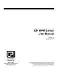
Toll Free: 1-888-865-6888
Tel: 510-226-8368 Fax: 510-226-8968
Email: [email protected]
Regulatory Notice
Legal Information
First English printing, October 2002
Information in this document has been carefully checked for accuracy; however, no guarantee is
given to the correctness of the contents. The information in this document is subject to change without notice. We are not liable for any injury or loss that results from the use of this equipment.
Safety Instructions
■
■
Unplug equipment before cleaning. Don’t use liquid or spray detergent; use a moist cloth.
Keep equipment away from excessive humidity and heat. Preferably, keep it in an air-conditioned environment with temperatures not exceeding 40º Celsius (104º Fahrenheit).
■
When installing, place the equipment on a sturdy, level surface to prevent it from accidentally falling and
causing damage to other equipment or injury to persons nearby.
■
When the drawer is in an open position, do not cover, block or in any way obstruct the gap between it
and the power supply. Proper air convection is necessary to keep it from overheating.
■
■
Arrange the equipment’s power cord in such a way that others won’t trip or fall over it.
If you are using a power cord that didn’t ship with the equipment, ensure that it is rated for the voltage
and current labeled on the equipment’s electrical ratings label. The voltage rating on the cord should be
higher than the one listed on the equipment’s ratings label.
■
■
Observe all precautions and warnings attached to the equipment.
If you don’t intend on using the equipment for a long time, disconnect it from the power outlet to prevent
being damaged by transient over-voltage.
■
Keep all liquids away from the equipment to minimize the risk of accidental spillage. Liquid
spilled on to the power supply or on other hardware may cause damage, fire or electrical shock.
■
Only qualified service personnel should open the chassis. Opening it yourself could damage the equipment and invalidate its warranty.
■
If any part of the equipment becomes damaged or stops functioning, have it checked by qualified service
personnel.
Regulatory Notices Federal Communications Commission (FCC)
This equipment has been tested and found to comply with the limits for a Class B digital device, pursuant to
Part 15 of the FCC rules. These limits are designed to provide reasonable protection against harmful interference in a residential installation.
Any changes or modifications made to this equipment may void the user’s authority to operate this equipment. This equipment generates, uses, and can radiate radio frequency energy and, if not installed and used
in accordance with the instructions, may cause harmful interference to radio communications.
However, there is no guarantee that interference will not occur in a particular installation. If this equipment
does cause harmful interference to radio or television reception, which can be determined by turning the
equipment off and on, the user is encouraged to try to correct the interference by one or more of the following measures:
■
■
■
Re-position or relocate the receiving antenna.
Increase the separation between the equipment and receiver.
Connect the equipment into an outlet on a circuit different from that to which the receiver is connected.
LCDK1009 / 1010 / 1011
Important Safeguards
Please read all of these instructions carefully before you use the device. Save this manual for future
reference.
What the warranty does not cover
■
■
Any product, on which the serial number has been defaced, modified or removed.
Damage, deterioration or malfunction resulting from:
□
□
□
□
□
□
□
□
■
Accident, misuse, neglect, fire, water, lightning, or other acts of nature, unauthorized product modification, or failure to follow instructions supplied with the product.
Repair or attempted repair by anyone not authorized by us.
Any damage of the product due to shipment.
Removal or installation of the product.
Causes external to the product, such as electric power fluctuation or failure.
Use of supplies or parts not meeting our specifications.
Normal wear and tear.
Any other causes which does not relate to a product defect.
Removal, installation, and set-up service charges.
Before Installation
■
It is very important to locate the KVM in a suitable environment.
■
The surface for placing and fixing the KVM should be stable and level or mounted into a suitable cabinet.
■
■
Make sure the place has good ventilation, is out of direct sunlight, away from sources of excessive dust,
dirt, heat, water, moisture and vibration.
Position LCD Keyboard Drawer with respect to related facilities.
Unpacking
The KVM comes with the standard parts shown in Package Content. Check and make sure they are included
and in good condition. If anything is missing, or damage, contact the supplier immediately.
P.1
LCDK1009 / 1010 / 1011
LCDK1009 / 1010 / 1011
PS/2 DB-15 KVM
Installation
P.2
LCDK1009 / 1010 / 1011
LCDK1009 / 1010 / 1011
PS/2 DB-15 KVM
Package Content (only for rackmount KVM)
1
5
al
User Manu
2
3
6
4
1 KVM switch x 1 pc
2 Screw M3.2 x 4.5mm x 4 pcs
3 Screw M4 x 10mm x 8 pcs
4 Bracket x 1 set
5 User manual x 1 pc
6 Power cord x 1 pc
P.3
LCDK1009 / 1010 / 1011
LCDK1009 / 1010 / 1011
PS/2 DB-15 KVM
Connection
Power
Local PS/2
Console
LCDK1009
Cascade
Power
Local PS/2
Console
LCDK1010
Cascade
Power
Local PS/2
Console
LCDK1011
Cascade
Connection
Rackmount KVM
PS2 cable supports
PS/2 interface server
Servers
DB-15 KVM port
P.4
LCDK1009 / 1010 / 1011
LCDK1009 / 1010 / 1011
PS/2 DB-15 KVM
Connection
KVM modules
PS2 cable supports
PS/2 interface server
Servers
back
DB-15 KVM port
Power
P.5
LCDK1009 / 1010 / 1011
LCDK1009 / 1010 / 1011
PS/2 DB-15 KVM
Cascade
■ Cascade up to 8 levels, 128 servers
■ Cascading multiple KVM by LCD-A1018 cable.
Cascade
Rackmount KVM
LCDK1011
Cascade
LCD-A1018 cable
Local PS/2
Console
LCDK1010
LCD-A1018
P.6
LCDK1009 / 1010 / 1011
LCDK1009 / 1010 / 1011
PS/2 DB-15 KVM
Cascade
■ Cascade up to 8 levels, 128 servers
■ Cascading multiple KVM by LCD-A1018 cable.
Cascade
KVM modules
back
16-port PS/2 DB-15 KVM module
Cascade
LCD-A1018 cable
Local PS/2
Console
LCDK1010
LCD-A1018
P.7
LCDK1009 / 1010 / 1011
Specifications
PS/2 DB-15 KVM
LCDK1009 / 1010 / 1011
▀
▀
▀
KVM Port
Number of ports:
4, 8 or 16
Connector:
DB-15 combo connector
Connectivity:
PS/2 3-in-1 KVM cable, up to 6, 10, 15 & 33 feet
Local Console
Graphic connector:
1 x DB-15 VGA
Resolution:
Up to 1600 x 1200
Input device:
2 x PS/2 for keyboard & mouse
Management
Multilingual OSD:
English, France, German, Spanish, Italian, Russian, Simplified Chinese, Japanese
Hotkey combination:
Scroll-lock, Cap-lock, Num-lock, Alt, Ctrl & Win
Security:
Password enable & disable, up to 8 users profile for port access
PC Selection:
Front button, OSD menu & hotkey
▀
Expansion:
Up to 128 servers by 8-level cascade
▀
Compatibility
▀
Multi-platform:
Mix PCs, SUNs, IBMs, HPs, DELLs Server
Support:
Windows Vista / 2003 / XP / 2000, Linux, Netware, Unix
Power
Input:
100 or 240V AC at 50 or 60 Hz via IEC type cord OR
AC / DC power adapter [email protected] (optional)
Option DC:
12V / 24V / 48V DC input
Consumption:
Max. 48 Watt, Standby 5 Watt
▀
Regulatory Approval:
FCC, CE
▀
Environmental
▀
Operating:
0 to 50°C
Storage:
-5 to 60°C
Relative humidity:
90%, non-condensing
Shock:
50G peak acceleration (11ms, half-sine wave)
Vibration:
58~100Hz / 0.98G (11ms / cycle)
Product Information
Dimension (W x D x H):
446 x 180 x 44 mm / 17.6 x 7.1 x 1.73 inch
Net weight:
LCDK1009: 3.5 kg / 8 lb
LCDK1010 / 1011: 4 kg / 9 lb
P.8
LCDK1009 / 1010 / 1011
KVM Button
PS/2 KVM Usage
Power ON
■ Turn off all servers and KVM switches
■ Make sure all cables / connectors are properly connected
■ Recommend Power ON sequence is monitor, KVM switch finally computer
Front Panel - Port LED Indications
4 ports (only for LCDK1009 )
Online Channel
Bank Button
Selected Channel
Bank
No.
Channel Select Button
Online Channel
Green LED on indicating a PC is connecting to the port
Selected Channel
RED LED on indicating a selected channel
Bank Button
Select the bank from1 to 8
Channel Select Button
Press to select channel from 1 to 8
Bank No.
7-Segment BANK LED indication
8 ports
BANK
Bank no.
PC port LEDs
Channel
button
Bank
button
16 ports
BANK
Bank no.
7-Segment BANK LED indication
PC port LEDs
Power : Orange LED on indicating a PC is connecting to the port
Access : Red LED on indicating a selected channel
Channel button
Press to select channel from 01 to 16
Bank button
Select the bank from 1 to 8
P.9
LCDK1009 / 1010 / 1011
Password
PS/2 KVM Usage
The password is enabled by default, the default password is “00000000” eight zeros (Do not use “0” on
number pad)
■
Set your own user name & password
1. Call KVM OSD menu by pressing the KVM hotkey Scroll Lock + Scroll
2. Select “CHANGE PASSWORD”
3. Enter “00000000” eight zeros in password field
(Do not use “0” on number pad)
4. Set your own password in “ENTER NEW PASSWORD” field
5. Retype your own new password in “RETYPE NEW PASSWORD” field
Lock + Space Bar
Remark: a. Blank has underscore. SPACE does not have underscore.
b. Press any alphanumeric key to move to next input item.
■
Change your password
1. Call KVM OSD menu by pressing the KVM hotkey Scroll Lock
2. Select “CHANGE PASSWORD”
3. Enter your own password
4. Change your password in “ENTER NEW PASSWORD” field
5. Retype your new password in “RETYPE NEW PASSWORD” field
+ Scroll Lock + Space Bar
Remark: a. Blank has underscore. SPACE does not have underscore.
b. Press any alphanumeric key to move to next input item.
■
Forget your password
Please contact your supplier for further support
Remark:
■ You must press the KVM hotkey within 2 seconds
■ A beep sound will be heard for successful entering KVM hotkey
P.10
LCDK1009 / 1010 / 1011
KVM OSD
PS/2 KVM Usage
OSD operation
next to the system name
The PC is powered on
next to the system name
The PC is selected
OSD
OSD menu on screen time
SCAN
Scan interval from one PC port to next PC when
applying auto scan
CHANGE PASSWORD
Change to a new password
Console ON/OFF
ON - quit the OSD menu without password
OFF - password is requested while quitting the
OSD menu
ESC
QUIT
TAB
NEXT
Select port for destination PC name and press
“Enter” to select
PgUp / PgDn
To switch previous or next bank
ENTER
Complete
INSERT
Edit
P.11
LCDK1009 / 1010 / 1011
KVM Hotkey
PS/2 KVM Usage
Hotkey
Function
Scroll Lock + Scroll Lock + Space Bar
Calling OSD menu
Scroll Lock + Scroll Lock +
Switch to previous port
Scroll Lock + Scroll Lock +
Switch to next port
Scroll Lock + Scroll Lock +
PgUp
Switch to previous bank
Scroll Lock + Scroll Lock +
Bank no. + Port no.
Switch to specific port
Scroll Lock + Scroll Lock +
PgDn
Switch to next bank
Scroll Lock + Scroll Lock +
S
Auto scan for powered on PC
Scroll Lock + Scroll Lock +
R
Reset to factory default setting
Scroll Lock + Scroll Lock +
B
Enable / Disable beeper sound
Scroll Lock + Scroll Lock +
F
Find port by name
Remarks:
Example of “Scroll Lock + Scroll Lock + Bank no. + Port no.”
■ Bank No. : 1 to 8
■ Port No. : 01 to 16
■ e.g. Bank 1 Port 4 : Scroll Lock + Scroll Lock + 1 + 0 + 4
■ e.g. Bank 2 Port 16 : Scroll Lock + Scroll Lock + 2 + 1 + 6
P.12
LCDK1009 / 1010 / 1011
Optional Accessories
PS/2 KVM Usage
1. PS/2 3-in-1 KVM cable
1.1 LCD-A1004
6 feet
1.2 LCD-A1005 10 feet
1.3 LCD-A1006 15 feet
1.4 LCD-A1007 33 feet
2. PS/2 KVM cascade cable
2.1 LCD-A1017
2 feet
2.2 LCD-A1018
6 feet
2.3 LCD-A1022 10 feet
2.4 LCD-A1023 15 feet
3. SUN / iMAC USB to PS/2 adapter
3.1 LCD-A1001
4. Power cord
4.1 IEC power cord
4.2 NEMA 5-15 power cord (US)
4.3 BS 1363 power cord (UK)
4.4 CEE 7/4 power cord (German)
4.5 AS 3112 power cord (Australia)
P.13
LCDK1009 / 1010 / 1011
DC Power 12V, 24V, 48V Input
PS/2 KVM Usage
12V
24V
48V
Input voltage:
12-Volt
24-Volt
48-Volt
Input range:
9 ~ 18V
18 ~ 36V
36 ~ 75V
- No load
50 mA
50 mA
50 mA
- Full load
4950 mA
2450 mA
1220 mA
Output voltage:
12-Volt
12-Volt
12-Volt
Output current:
4.16A
4.16A
4.16A
Efficiency
84%
85%
85%
Model
Input rating
Input current
Output rating
Remarks:
■ Package does not include power cord
Troubleshooting
1.
There is no LED display on KVM membrane switch
Make sure the power adapter plugged into the KVM Switch, if the LED’s still off, perform soft
i.
reset to KVM switch.
ii.
Power cycle KVM switch.
2.
I can power on the KVM, but I am not getting any picture at all, how can I solve this?
Switching to another port and checking if this port has the same problem
a.
If you switch to another port, please check the screen resolution is the same.
b.
Check the OSD menu is available on the hot keys “Scroll lock + Scroll lock + space bar”.
If the problems persist, please make sure the cables are inserted properly and the boot up
sequence is followed.
3.
The screen is on but the keyboard and mouse don’t work
i.
Check the server by using a different keyboard and mouse.
ii.
For PS/2 servers
The keyboard and mouse are not hot pluggable.
iii.
For USB servers
Unplug and plug allowing a few seconds for the bus emulation process to complete.
iv
Do not press any keys on the keyboard whilst the server is booting up. This can cause a
keyboard error or cause the keyboard not to detect the KVM switch.
v.
Try a different keyboard, but use only 101/102/104-key keyboard
vi.
Avoid moving the mouse whilst switching the KVM ports.
4.
There is no LED display on the dongle
The LED on the dongle will flash when plugged into the USB or PS/2 server. The light will then
become steady when the KVM switch has connected. If the LED light is on and not flashing when
plugged into server, please unplug the USB or PS/2 and try again. Or try another good dongle to
verify if problem still appears. If the problem persists, please contact your supplier.
P.14
LCDK1009 / 1010 / 1011
FAQ
General
1.
How do the KVM switches allow the user to switch ports?
There are two ways to switch ports. One is the membrane buttons on the front and the other way is
with Hot-key commands.
2.
What operating systems do the KVMs support?
The KVMs support multi-platform support allows you to control Windows-based computers, Sun Solaris systems, Linux, or even Macs by a single KVM switch. The KVM switches support multi-platform
operating systems including but not limited to DOS, Windows 95/98/ME/NT/2000/XP, Linux, Solaris
and Mac OS.
3.
Do I have to power down the KVMs to add a new server ?
The KVMs are hot-pluggable and allows servers or devices to be added or removed without powering down the switch, but components of connected devices, such as the servers, may not be hotpluggable. We suggest that turn off power to all devices before connecting them.
4.
Why I can’t login with default password on KVM switch
The default username and password for the KVM switch is eight zeros - “00000000”. Please check
i.
The “Num lock” is not turned on. (for notebook type keyboard)
ii.
The numeric (number) keys on the number pad are not accepted by KVM, only the main
number keys.
5.
Can I disable the KVM password ?
Yes, for Matrix KVM, Cat6 KVM & Combo DB-15 KVM, user can disable/ enable the KVM password
by hotkey.
No, for PS/2 KVM, user can’t disable the KVM password.
6.
What do I do if I forget the password?
If the user change the default password and lose the password, please contact the supplier for
further support.
7.
How many levels of KVM cascade are supported?
8 levels are supported.
8.
Can I cascade the different types KVM switches together ?
No, only same type KVM can cascade together. (e.g. PS/2 to PS/2, USB to USB,..)
9.
Why am I getting ghosting images or shadowing?
Check that all video cables are inserted properly.
i.
ii.
Check whether the KVM supports the resolution and refresh rate on your servers.
iii.
Check whether the graphics card you are using supports the resolution and refresh rate on
your server or not.
iv.
Connect the monitor directly into the servers you are having trouble with to see if problem
still appears.
P.15
LCDK1009 / 1010 / 1011
FAQ
10.
The server VGA resolution does not match the resolution of monitor ?
The KVM supports DDC function which will dynamically detect and the DDC data.
The problem may come from the power on sequence.
For KVM switch
The recommended power on sequence is - monitor, KVM switch and then servers.
For remote console box
It supports DDC function but does not support hot-plug, the recommend power on sequence
is – monitor, remote console box and then servers.
PS/2 KVM
Can I connect to Suns (USB type) and/or Macs system to PS/2 KVM switches ?
Yes. Use PS/2 to USB converter (LCD-A1001) to convert the keyboard & mouse of PS/2 KVM cable
(LCD-A1004) to USB interface. The LCD-A1001 includes the built-in mapping of all the Suns & Macs system
hotkey.
Combo KVM
Can the Combo KVM support the keyboard or monitor with a USB hub built-in ?
The Combo KVM switch is only capable of passing Keyboard, Mouse and Video signals. As a result,
other USB devices with a USB hub will not work.
Can I use the touchscreen with KVM switches ?
No, the KVM switches do not support the touchscreen driver
Two console KVM
What is the resolution support on remote console ?
The remote console can support up to 1,000 feet at 1024 x 768, and up to 500 feet at 1600 x 1200.
Why am I getting ghosting images or shadowing on remote console ?
Press “Scroll lock + Scroll lock + A” on the keyboard connected to remote console box to force autoadjusting the video signal to optimize.
Cat6 KVM
Can I use standard Cat6 cable for dongle ?
The dongle can support Cat5/5e/6 straight cable. To maximum performance and stability, we strongly
recommend applying the Cat6 cable (LCD-A2011 /12 / 13 / 14 / 15 / 16) from us, we are designed and
qualification tested using pre-made (factory made) Cat5e cable assemblies in fixed lengths.
Using this type of cable assembly will provide excellent link connections and data communication. As
poorly made field cable assemblies can cause damage to the Cat5 KVMs & dongles and result in a
poor or intermittent link. The warranties do not apply to damage resulting from user-supplied cable.
The company reserves the right to modify product specifications without prior notice and assumes no responsibility for any error which
may appear in this publication.
All brand names, logo and registered trademarks are properties of their respective owners.
Copyright 2008 Synergy Global Technology Inc. All rights reserved.
P.16
LCDK1009 / 1010 / 1011