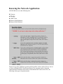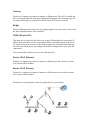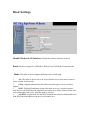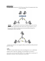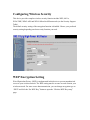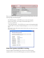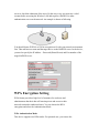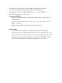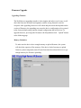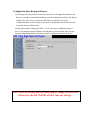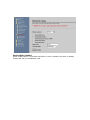
1
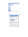
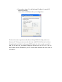
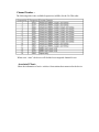
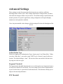
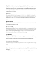
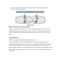
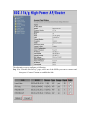
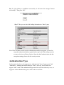
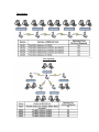
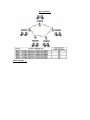
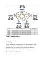
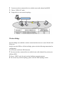
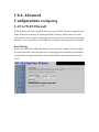
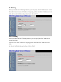
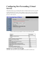
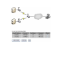
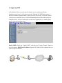
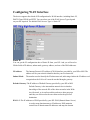
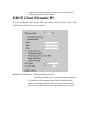
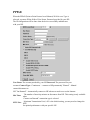
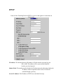
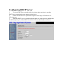
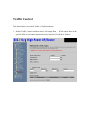
Wireless LAN Device Series
High-Power 400mW 802.11b/g Router
AIP-610H
User Manual
Version. 6.1
Preface
This guide is for the networking professional who installs and manages the AIP-W610H
product hereafter referred to as the “device”. To use this guide, you should have
experience working with the TCP/IP configuration and be familiar with the concepts and
terminology of wireless local area networks.
Ch 1. AIP-W610H Pack
Packing List
Before you start to install the AIP-W610H, make sure the package contains the following
items:
User CD
12VDC Power Adapter
2dBi Antenna
AIP-W610H Device
Ch 2. First Time Configuration
Before Start to Configure
There are two ways to configure the device, one is through web-browser, and the other is
through Secure Shell CLI interface. To access the configuration interfaces, make sure you
are using a computer connected to the same network as the device. The default IP address
of the device is 192.168.2.1, and the subnet-mask is 255.255.255.0.
In order to communicate with AIP-W610H, you have to configure the IP addresses of
your computer to be compatible with the device. The router supports DHCP server and it
is disabled as default. Users that configure your IP address as “Use the following IP
address”, check the following IP configuration instruction.
Note:
1. The default network setting of the device:
IP address: 192.168.2.1
Subnet Mask: 255.255.255.0
DHCP Server: disabled
2. In the following TCP/IP configuration guide, the IP address
“192.168.2.2 ” is assumed to be your IP address. You need to specify IP
addresses manually.
Please DO NOT choose 192.168.2.1 for the IP address (192.168.2.1)
has been set as the default IP for this device.
3. The following TCP/IP configuration guide uses windows XP as the
presumed operation system.
Procedures to configure IP addresses for your computer
1. If you are in Classic Start menu view, click Start Settings Control
Panel Network Connections.
If you are in Start menu view, click Start Control Panel Network
Connections.
2. Double click “Local Area Connection”
3. Choose Internet Protocol (TCP/IP) and click Properties.
4. You need to choose “Use the following IP address” to specify IP
addresses manually.
Please click the OK button after your configuration.
The device has three operation modes (Router/Bridge/WISP). In bridge mode, also
known as AP Client, you can access the device by both WLAN (Wireless Local Area
Network) and wired LAN. And in router/WISP modes, the device can be accessed by
both WLAN and LAN. The default IP addresses for the device are 192.168.2.1, so you
need to make sure the IP address of your PC is in the same subnet as the device, such as
192.168.2.X.
Knowing the Network Application
AIP-W610H can act as the following roles
● Gateway
● Bridge
● WISP Client
● Router (WAN Ethernet)
● Router (WAN Wireless)
The device provides 5 different operation modes and the wireless radio of device can act
as Gateway/Bridge/WISP Client/Router/Router. The operation mode is about the
communication mechanism between the wired Ethernet NIC and wireless NIC, the
following is the types of operation mode.
Gateway
The device is supposed to connect to internet via Ethernet port. The NAT is enabled and
PCs in LAN ports share the same IP to ISP through WAN port. The connection type can
be setup in WAN page by using PPPoE, DHCP client, PPTP client or static IP.
Bridge
The wired Ethernet and wireless NIC are bridged together. Once the mode is selected, all
the WAN related functions will be disabled.
WISP (Wireless ISP)
This mode can let you access the AP of your wireless ISP and share the same public IP
address form your ISP to the PCs connecting with the wired Ethernet port of the device.
To use this mode, first you must set the wireless radio to be client mode and connect to
the AP of your ISP then you can configure the WAN IP configuration to meet your ISP
requirement.
The wireless radio of the device acts as the following roles.
Router (WAN Ethernet)
The device is supposed to connect to internet via Ethernet port and it will act as router.
NAT system will be disabled.
Router (WAN Wireless)
The device is supposed to connect to internet via Wireless port and it will act as router.
NAT system will be disabled.
Hereafter are some topologies of network application for your reference.
Basic Settings
Disable Wireless LAN Interface: Disable the wireless interface of device
Band: The device supports 2.4GHz(B), 2.4GHz(G) and 2.4GHz(B+G) mixed modes.
Mode: The radio of device supports different modes as following:
1
AP : The radio of device acts as an Access Point to serves all wireless clients to
join a wireless local network.
2
Client : Support Infrastructure and Ad-hoc network types to act as a wireless
adapter.
3
WDS : Wireless Distribution System, this mode serves as a wireless repeater,
only devices with WDS function supported can connect to it, all the wireless clients can’t
survey and connect the device when the mode is selected.
4
AP+WDS : Support both AP and WDS functions, the wireless clients and devices
with WDS function supported can survey and connect to it.
Infrastructure :
This type requires the presence of 802.11b/g Access Point. All communication is done
via the Access Point.
Ad Hoc :
This type provides a peer-to-peer communication between wireless
stations. All the communication is done from Client to Client without any Access
Point involved. Ad Hoc networking must use the same SSID and channel for
establishing the wireless connection.
In client mode, the device can’t support the Router mode function including Firewall
and WAN settings.
SSID :
The SSID is a unique identifier that wireless networking devices use to establish and
maintain wireless connectivity. Multiple access point/bridges on a network or
sub-network can use the same SSID. SSIDs are case sensitive and can contain up to 32
alphanumeric characters. Do not include spaces in your SSID.
Channel Number :
The following table is the available frequencies (in MHz) for the 2.4-GHz radio:
When set to “Auto”, the device will find the least-congested channel for use.
Associated Client :
Show the information of active wireless client stations that connected to the device.
Advanced Settings
These settings are only for more technically advanced users who have sufficient
knowledge about wireless LAN. These settings should not be changed unless you know
what effect the changes will have on your device. The default setting is optimized for the
normal operation. For specific application, setting configuration will required highly
attention to reach optimistic condition.
Note: Any unreasonable value change to default setting will reduce the throughput of the
device.
Authentication Type
The device supports two Authentication Types “Open system” and “Shared Key”. When
you select “Share Key”, you need to setup “WEP” key in “Security” page (See the next
section). The default setting is “Auto”. The wireless client can associate with the device
by using one of the two types.
Fragment Threshold
The fragmentation threshold determines the size at which packets are fragmented (sent as
several pieces instead of as one block). Use a low setting in areas where communication
is poor or where there is a great deal of radio interference. This function will help you to
improve the network performance.
RTS Threshold
The RTS threshold determines the packet size at which the radio issues a request to send
(RTS) before sending the packet. A low RTS Threshold setting can be useful in areas
where many client devices are associating with the device, or in areas where the clients
are far apart and can detect only the device and not each other. You can enter a setting
ranging from 0 to 2347 bytes.
Data Rate
The standard IEEE 802.11b/11g supports 1, 2, 5.5, 11 / 6, 9, 12, 18, 24, 36, 48 and 54
Mbps data rates. You can choose the rate that the device uses for data transmission. The
default value is “auto”. The device will use the highest possible selected transmission
rate.
Beacon Interval
The beacon interval is the amount of time between access point beacons in mini-seconds.
The default beacon interval is 100.
Broadcast SSID
Broadcasting the SSID will let your wireless clients find the device automatically. If you
are building a public Wireless Network, disable this function can provide better security.
Every wireless stations located within the coverage of the device must connect this
device by manually configure the SSID in your client settings.
Int. Roaming
This function will let Wireless Stations roam among a network environment with
multiple devices. Wireless Stations are able to switch from one device to another as they
move between the coverage areas. Users can have more wireless working range.
An example as the following figure.
You should comply with the following instructions to roam among the wireless coverage
areas.
Note : For implementing the roaming function, the setting MUST comply the following
two items.
All the devices must be in the same subnet network and the SSID must be the same.
If you use the 802.1x authentication, you need to have the user profile in these
devices for the roaming station.
Block WLAN Relay (Isolate Client)
The device supports isolation function. If you are building a public Wireless Network,
enable this function can provide better security. The device will block packets between
wireless clients (relay). All the wireless clients connected to the device can’t see each
other.
Transmit Power
The device supports ten transmission output power levels
400,315,250,200,150,100,63,50,32 and 16mW for CCK (802.11b) mode and seven
transmission output power levels 100,63,32,16,6,3 and 2mW for OFDM (802.11g) mode.
User can adjust the power level to change the coverage of the device. Every wireless
stations located within the coverage of the device also needs to have the high power radio.
Otherwise the wireless stations only can survey the device, but can’t establish connection
with device.
Configuring Wireless Security
This device provides complete wireless security function include WEP, 802.1x,
WPA-TKIP, WPA2-AES and WPA2-Mixed in different mode (see the Security Support
Table).
The default security setting of the encryption function is disabled. Choose your preferred
security setting depending on what security function you need.
WEP Encryption Setting
Wired Equivalent Privacy (WEP) is implemented in this device to prevent unauthorized
access to your wireless network. The WEP setting must be as same as each client in your
wireless network. For more secure data transmission, you can change encryption type to
“WEP” and click the “Set WEP Key” button to open the “Wireless WEP Key setup”
page.
When you decide to use the WEP encryption to secure your WLAN, please refer to the
following setting of the WEP encryption:
64-bit WEP Encryption:64-bit WEP keys are as same as the encryption
method of 40-bit WEP. You can input 10 hexadecimal digits (0~9, a~f
or A~F) or 5 ACSII chars.
128-bit WEP Encryption:128-bit WEP keys are as same as the encryption method
of 104-bit WEP. You can input 26 hexadecimal digits (0~9, a~f or A~F) or 10 ACSII
chars.
The Default Tx Key field decides which of the four keys you want to use in your
WLAN environment.
WEP Encryption with 802.1x Setting
The device supports external RADIUS Server that can secure networks against
unauthorized access. If you use the WEP encryption, you can also use the RADIUS
server to check the admission of the users. By this way every user must use a valid
account before accessing the Wireless LAN and requires a RADIUS or other
authentication server on the network. An example is shown as following.
You should choose WEP 64 or 128 bit encryption to fit with your network environment
first. Then add user accounts and the target device to the RADIUS server. In the device ,
you need to specify the IP address、Password (Shared Secret) and Port number of the
target RADIUS server.
WPA Encryption Setting
WPA feature provides a high level of assurance for end-users and
administrators that their data will remain private and access to their
network restricted to authorized users. You can choose the WPA
encryption and select the Authentication Mode.
WPA Authentication Mode
This device supports two WPA modes. For personal user, you can use the
Pre-shared Key to enhance your security setting. This mode requires only an
access point and client station that supports WPA-PSK. For Enterprise,
authentication is achieved via WPA RADIUS Server. You need a RADIUS or
other authentication server on the network.
Enterprise (RADIUS):
When WPA Authentication mode is Enterprise (RADIUS), you have to add user
accounts and the
target device to the RADIUS Server. In the device , you need to specify the IP
address、Password
(Shared Secret) and Port number of the target RADIUS server.
Pre-Share Key:
This mode requires only an access point and client station that supports
WPA-PSK. The WPA-PSK settings include Key Format, Length and Value. They
must be as same as each wireless client in your wireless network. When Key format
is Passphrase, the key value should have 8~63 ACSII chars. When Key format is
Hex, the key value should have 64 hexadecimal digits (0~9, a~f or A~F).
Configuring as WLAN Client Adapter
This device can be configured as a wireless Ethernet adapter. In this mode,
the device can connect to the other wireless stations (Ad-Hoc network type)
or Access Point (Infrastructure network type) and you don’t need to install
any driver.
Quick start to configure
Step 1. In “Basic Settings” page, change the Mode to “Client” mode. And key in the
SSID of the AP you want to connect then press “Apply Changes” button to apply
the change.
Step 2. Check the status of connection in “Status” web page
The alternative way to configure as following:
Step 1. In “Wireless Site Survey” page, select one of the SSIDs you want to connect and
then press “Connect” button to establish the link.
Step 2. If the linking is established successfully. It will show the message”Connect
successfully”. Then press “OK”.
Step 3. Then you can check the linking information in “Status” page.
Note: If the available network requires authentication and data encryption, you need to
setup the authentication and encryption before step1 and all the settings must be
as same as the Access Point or Station. About the detail authentication and data
encryption settings, please refer the security section.
Authentication Type
In client mode, the device also supports two Authentication Types “Open system” and
“Shared Key”. Although the default setting is “Auto”, not every Access Points can
support “Auto” mode. If the authentication type on the Access Point is knew by user, we
suggest to set the authentication type as same as the Access Point.
Data Encryption
In client mode, the device supports WEP and WPA Personal/Enterprise except
WPA2 mixed mode data encryption. About the detail data encryption settings,
please refer the security section.
Ch 3. Configuring WDS
Wireless Distribution System (WDS) uses wireless media to communicate with the other
devices, like the
Ethernet does. This function allows one or more remote LANs connect with the local
LAN. To do this, you must
set these devices in the same channel and set MAC address of other devices you want to
communicate with in the
WDS AP List and then enable the WDS.
When you decide to use the WDS to extend your WLAN, please refer the following
instructions for configuration.
1. The bridging devices by WDS must use the same radio channel.
2. When the WDS function is enabled, all wireless stations can’t connect the device.
3. If your network topology has a loop, you need to enable the 802.1d Spanning Tree
function.
4. You don’t need to add all MAC address of devices existed in your network to WDS
AP List. WDS AP List only needs to specify the MAC address of devices you need to
directly connect to.
5. The bandwidth of device is limited, to add more bridging devices will split the more
bandwidth to every bridging device.
WDS network topology
In this section, we will demonstrate the WDS network topologies and WDS AP List
configuration. You can setup the four kinds of network topologies: bus, star, ring and
mesh.
In this case, there are five devices with WDS enabled: WDS1, WDS2, WDS3, WDS4 and
WDS5.
Bus topology:
Star topology:
Ring topology:
Mesh topology:
WDS Application
Wireless Repeater
Wireless Repeater can be used to increase the coverage area of another device (Parent
AP). Between the Parent AP and the Wireless Repeater, wireless stations can move
among the coverage areas of both devices. When you decide to use the WDS as a
Repeater, please refer the following instructions for configuration.
1 In AP mode, enable the WDS function.
2 You must set these connected devices with the same radio channel and SSID.
3 Choose “WDS+AP” mode.
4 Using the bus or star network topology.
Wireless Bridge
Wireless Bridge can establish a wireless connection between two or more Wired LANs.
When you
decide to use the WDS as a Wireless Bridge, please refer the following instructions for
configuration.
1 In AP mode, enable the WDS function.
2 You must set these connected devices with the same radio channel, but you may use
different SSID.
3 Choose “WDS” mode for only wireless backbone extension purpose.
4 You can use any network topology, please refer the WDS topology section.
Ch 4. Advanced
Configurations Configuring
LAN to WAN Firewall
Filtering function is used to block packets from LAN to WAN. The device supports three
kinds of filter Port Filtering, IP Filtering and MAC Filtering. All the entries in current
filter table are used to restrict certain types of packets from your local network to through
the device. Use of such filters can be helpful in securing or restricting your local network.
Port Filtering
When you enable the Port Filtering function, you can specify a single port or port ranges
in current filter table. Once the source port of outgoing packets match the port definition
or within the port ranges in the table, the firewall will block those packets from LAN to
WAN.
IP Filtering
When you enable the IP Filtering function, you can specify local IP Addresses in current
filter table. Once the source IP address of outgoing packets match the IP Addresses in the
table, the firewall will block this packet from LAN to WAN.
MAC Filtering
When you enable the MAC Filtering function, you can specify the MAC Addresses in
current filter table.
Once the source MAC Address of outgoing packets match the MAC Addresses in the
table,
the firewall will block this packet from LAN to WAN.
Configuring Port Forwarding (Virtual
Server)
This function allows you to automatically redirect common network services to a specific
machine behind the NAT firewall. These settings are only necessary if you wish to host
some sort of server like a web server or mail server on the private local network behind
the device's NAT firewall.
The most often used port numbers are shown in the following table.
Multiple Servers behind NAT Example:
In this case, there are two PCs in the local network accessible for outside users.
Configuring DMZ
A Demilitarized Zone is used to provide Internet services without sacrificing
unauthorized access to its local private network. Typically, the DMZ host contains
devices accessible to Internet traffic, such as Web (HTTP) servers, FTP servers, SMTP
(e-mail) servers and DNS servers. So that all inbound packets will be redirected to the
computer you set. It also is useful while you run some applications (ex. Internet game)
that use uncertain incoming ports.
Enable DMZ: Enable the “Enable DMZ”, and then click “Apply Changes” button to
save the changes. DMZ Host IP Address: Input the IP Address of the computer that you
want to expose to Internet.
Configuring WAN Interface
The device supports four kinds of IP configuration for WAN interface, including Static IP,
DHCP Client, PPPoE and PPTP. You can select one of the WAN Access Types depend
on your ISP required. The default WAN Access Type is “Static IP”.
Static IP
You can get the IP configuration data of Static-IP from your ISP. And you will need to
fill the fields of IP address, subnet mask, gateway address, and one of the DNS addresses.
IP Address:
Subnet Mask:
The Internet Protocol (IP) address of WAN interface provided by your ISP or MIS. The
address will be your network identifier besides your local network.
The number used to identify the IP subnet network, indicating whether the IP address can b
recognized on the LAN or if it must be reached hrough a gateway.
Default Gateway: The IP address of Default Gateway provided by your ISP or MIS.
Default Gateway is the intermediate network device that has
knowledge of the network IDs of the other networks in the Wide
Area Network, so it can forward the packets to other gateways
until they are delivered to the one connected to the specified
destination.
DNS 1~3: The IP addresses of DNS provided by your ISP. DNS (Domain Name Server)
is used to map domain names to IP addresses. DNS maintain
central lists of domain name/IP addresses and map the domain
names in your Internet requests to other servers on the Internet
until the specified web site is found.
DHCP Client (Dynamic IP)
All IP configuration data besides DNS will obtain from the DHCP server when
DHCP-Client WAN Access Type is selected.
DNS1~3: The IP addresses of DNS provided by your ISP.
DNS (Domain Name Server) is used to map domain names
to IP addresses. DNS maintain central lists of domain name/IP
addresses and map the domain names in your Internet requests to
other servers on the Internet until the specified web site is found.
PPPoE
When the PPPoE (Point to Point Protocol over Ethernet) WAN Access Type is
selected, you must fill the fields of User Name, Password provided by your ISP.
The IP configuration will be done when the device successfully authenticates
with your ISP.
User Name: The account provided by your ISP Password: The password for your
account. Connect Type: “Continuous “ : connect to ISP permanently ”Manual” : Manual
connect/disconnect to
ISP ”On-Demand” : Automatically connect to ISP when user need to access the Internet.
The number of inactivity minutes to disconnect from ISP. This setting is only available
Idle Time:
when
“Connect on Demand” connection type is selected.
Maximum Transmission Unit, 1412 is the default setting, you may need to change the
MTU Size:
MTU
for optimal performance with your specific ISP.
DNS1~3:
The IP addresses of DNS provided by your ISP.
DNS (Domain Name Server) is used to map domain names to IP addresses. DNS maintain
central lists of domain name/IP addresses and map the domain names in your Internet
requests
to other servers on the Internet until the specified web site is found.
PPTP
Point to Point Tunneling Protocol (PPTP) is a service that applies to connections in
Europe only.
IP Address: The Internet Protocol (IP) address of WAN interface provided by your
ISP or MIS. The address will be your network identifier
besides your local network.
Subnet Mask: The number used to identify the IP subnet network, indicating whether the
IP address can be recognized on the LAN or if it must be
reached through a gateway.
Server IP Address: The IP address of PPTP server (Default Gateway)
User Name: The account provided by your ISP
Password: The password of your account
MTU Size: Maximum Transmission Unit, 1412 is the default setting, you may need to
change the MTU for optimal performance with your specific
ISP.
DNS1~3: The IP addresses of DNS provided by your ISP. DNS (Domain Name Server)
is used to map domain names to IP addresses. DNS maintain
central lists of domain name/IP addresses and map the domain
names in your Internet requests to other servers on the Internet
until the specified web site is found.
Configuring DHCP Server
1
To use the DHCP server inside the device, please make sure there is no other
DHCP server existed in the same network as the device.
2
Enable the DHCP Server option and assign the client range of IP addresses as
following page.
3
When the DHCP server is enabled and also the device router mode is enabled then
the default gateway for all the DHCP client hosts will set to the IP address of device.
Traffic Control
This functionality can control Traffic of Up/Downstream
1. Enable Traffic Control and then enter LAN output Rate 、WAN output Rate in the
specific field. It can control maximum rate by interface, IP and MAC address
Firmware Upgrade
Upgrading Firmware
The Web-Browser upgrading interface is the simplest and safest way for user, it will
check the firmware checksum and signature, and the wrong firmware won’t be
accepted. After upgrading, the device will reboot and please note that depends on the
version of firmware, the upgrading may cause the device configuration to be restored
to the factory default setting, and the original configuration data will be lost! To
upgrade firmware, just assign the file name with full path then click ” Upload” button
as the following page.
Memory Limitation
To make sure the device have enough memory to upload firmware, the system
will check the capacity of free memory, if the device lack of memory to upload
firmware, please temporarily turn-off some functions then reboot the device to get
enough memory for firmware uploading.
Configuration Data Backup & Restore
Rest Setting to Factory Default Value Since the device is designed for outdoor used,
there is no interface outside the housing to reset the configuration value to the factory
default value. The device provides the Web-Browser interface to rest the
configuration data. After resetting it, the current configuration data will be lost and
restored to factory default value.
Saving & Restoring Configuration Data : To save & restore configuration data of
device, just assign the target filename with full path at your local host, then you can
backup configuration data to local host or restore configuration data to the device.
Note: After All setting, need to check Apply Change to take effect.
Otherwise, the AIP-W610H will not take any change.
Enable MESH (OLSRD):
When enable MESH. This means that when a route is needed, the route is already
known and can be immediately used.
HOW To List for all detail control and script
=> HOW TO USE BANDWIDTH CONTROL
NOTE: This control uses QoS with HTB.
Bandwidth control it's done through Traffic Control menu, via web interface or via
/etc/cbu.conf file. You can limit all traffic via Interface control or you can control via IP
and/or MAC basis. Further more, you can create QoS groups and share the group rate among
the members of that group. You can as well, guarantee minimum rate for group member.
Ex:
CASE 1:
You are going to install this equipment for a Wireless ISP client, which has maximum 256
kbit download speed and 128 kbit upload. Go to traffic control menu and enable "Interface
traffic control", with the values:
LAN Output rate: 256 -> LAN control downloads
WAN Output rate: 128 -> WAN control uploads
With interface based traffic control, you can control maximum interface speed, regardless
NAT function enabled or not.
CASE 2:
You are going to install this equipment for an inn establishment, which have 3 clients. Each
client wants to have their own speed rate.
With this scenario, you can control them via IP or MAC address. To do it so, enable you
desired option (IP/MAC control) and put your client's IP/MAC address. One entry for each
client. This way, you will limit desired speed for each individual client. Further more, you can
activate firewall option to block any other machine not listed.
To use IP/MAC control, you must disable interface traffic control.
=> HOW TO USE BANDWIDTH CONTROL WITH QoS GROUP OPTION
QoS groups are used to limit a group of users, and share the total rate. The idea here is
simple:
- Any member of the group can reach the total rate of the group
ٛ
- The total sum of all member's traffic together, will not exceed the total rate of the
ٛ
group
- Any member of the group can have guaranteed bandwidth
ٛ
-Equal bandwidth sharing
Ex:
Let's back to our example above. Inn establishment, which have 3 clients. All clients have
256 kbit speed contract. One of the clients has 2 machines, which he likes to use internet on
both. How to solve this case, if he has 256 kbit speed and two machines? Simple. Let's enable
QoS group option.
Go to traffic control and enable QoS group option. Create a group as follow:
Group ID: 1
LAN Out rate: 256 -> Total rate for download
WAN Out rate: 256 -> Total rate for upload
Next thing to do is to put the two machines of that client inside the group (via IP or MAC
control), as follow:
Group ID: 1 -> Member of QoS group ID 1
IP: 192.168.x.x -> machine's 1 IP
LAN Out rate: 0 -> 0 for equal sharing
WAN Out rate: 0 -> 0 for equal sharing
Group ID: 1 -> Member of QoS group ID 1
IP: 192.168.x.x -> machine's 2 IP
LAN Out rate: 0 -> 0 for equal sharing
WAN Out rate: 0 -> 0 for equal sharing
This is the example for equal sharing between those 2 machines. Now, let's suppose that, this
client wants to have at least 200 kbit guaranteed to machine 1. Simple to do it, as follow:
Group ID: 1 -> Member of QoS group ID 1
IP: 192.168.x.x -> machine's 1 IP
LAN Out rate: 200 -> 200 kbit guaranteed
WAN Out rate: 200 -> 200 kbit guaranteed
Group ID: 1 -> Member of QoS group ID 1
IP: 192.168.x.x -> machine's 2 IP
LAN Out rate: 0
WAN Out rate: 0
The other 2 clients will have no group:
Group ID: 0 -> Does not belong to any group
IP: 192.168.x.x -> Client 2
LAN Out rate: 256
WAN Out rate: 256
Group ID: 0
IP: 192.168.x.x
LAN Out rate: 256
WAN Out rate: 256
-> Does not belong to any group
-> Client 3
=> HOW TO GUARANTEE BANDWIDTH FOR A VOIP SYSTEM
We will use this example to show how easy is to guarantee bandwidth for a voip system for
instance. The main objective here is, to set up simple scenario with no effort. The scenario is:
-Internet connection of 300 kbit
- Guarantee 64 kbit for Voip machine
ٛ
- Don't need to enter every single machine as group member
ٛ
You are going to install this equipment, for some company which has a voip system and
some small network (let's say, 30 computers). We want that all machines have internet access.
Let's set up our QoS group:
Group ID: 1
LAN Out rate: 300 -> Internet Total download rate
WAN Out rate: 300 -> Internet Total upload rate
put our voip machine in first place:
now, the first thing to do is to
Group ID: 1 -> Member of QoS group ID 1
IP: 192.168.x.x -> Voip machine IP address
LAN Out rate: 64 -> 64 kbit guaranteed
WAN Out rate: 64 -> 64 kbit guaranteed
Next, instead of put every single machine inside the control list, we will put this rule:
Group ID: 1 IP: 0.0.0.0 LAN Out rate: 0 WAN Out rate: 0
Simple as that. How dos it work?
-> Member of QoS group ID 1 -> 0.0.0.0= the entire network
- When there is no VOIP traffic, the entire network can reach 300 kbit internet connections.
As soon as the voip system starts to operate, the QoS system will reserve 64 kbit for the voip.
But, if the boss machine wants to have 128 kbit guaranteed as well? Proceed as follow:
Group ID: 1 LAN Out rate: 300 WAN Out rate: 300
Group ID: 1 IP: 192.168.x.x LAN Out rate: 64 WAN Out rate: 64
Group ID: 1 IP: 192.168.x.x LAN Out rate: 128 WAN Out rate: 128
Group ID: 1 IP: 0.0.0.0 LAN Out rate: 0 -> Internet Total download rate -> Internet Total
upload rate
-> Member of QoS group ID 1
-> Voip machine IP address -> 64 kbit guaranteed -> 64 kbit guaranteed
-> Member of QoS group ID 1
-> Boss ip address -> 128 kbit guaranteed -> 128 kbit guaranteed
-> Member of QoS group ID 1 -> 0.0.0.0= the entire network WAN Out rate: 0
And so on. We can guarantee as many machines as we want. The rest, will share...
=> TRAFFIC CONTROL VIA CONFIG FILE INSTEAD OF WEB INTERFACE
This version allow unlimited IP or MAC address traffic control, via /etc/cbu.conf file. Via
WEB interface you can only control up to 40 entries. The file /etc/cbu.conf uses the same idea
as via WEB interface. After you’re done with file changes, you have to type the following
commands in order, to save and activate the changes:
# salvar
# /bin/cbu.sh
# /bin/firewall.sh
NOTE: REMEMBER TO ACTIVATE TRAFFIC CONTROL VIA WEB INTERFACE.
=> NOTES ABOUT SSH ACCESS
This firmware version comes with SSH2 server. As default, we have the user "root" with
password "root".
To change the root's password, proceed as follow:
- Access the equipment through SSH terminal ( putty for example )
-type: "passwd"
-Type your new password and confirm
- Now, to permanet save the change, type: "salvar" - save in portuguese :)
This version comes with SSH client program. You can use it to remotelly connect to another
equipment.
=> FREEDOM TO CHANGE/EDIT PERSONAL SCRIPT VIA WEB
Go to menu Management -> Edit Script File. You can change the way you want. After that,
just press Save button. Now your script will be saved and executed!
=> FREEDOM TO CHANGE/EDIT/CREATE SCRIPTS VIA SSH TERMINAL
When connected via SSH, you can edit/create scripts inside /etc structure. To do it, there
is a popular linux editor: "vi".
All files from /etc, will be permanently saved if you type "salvar". So, be carefull with your
changes...
The main script file is /etc/init.sh, which is responsible for the entire system. You can create
your own script inside /etc and call it from /etc/init.sh.
NOTE: DO NOT FORGET TO TYPE "salvar" AFTER ANY CHANGE TO PERMANENTLY SAVE IT
INSIDE THE FLASH MEMORY! AGAIN, BE EXTRA CEREFULL WITH YOUR CHANGES!
=> HOW TO FIX MAC ADDRESS TO CERTAIN IP AND STATIC LEASE VIA DHCP
(VIA SSH TERMINAL)
With just one file it's possible to lease static ip based on mac addr and to tie-up this pair
mac/ip. To do it, you have to edit this file /etc/ethers like that:
# John
00:12:34:51:fd:ea 192.168.2.100
# Jhony
00:4f:23:fb:ce:3d 192.168.2.101
After that, save it. Now, type "salvar". To put it to work straightaway, type: "init.sh gw all"
With this file, the DHCP server will give IP ADDR based on MAC ADDR. Further more,
the equipment will only respond for that IP ADDR with that MAC ADDR.
=> HOW TO FIX MAC ADDRESS TO CERTAIN IP AND STATIC LEASE VIA DHCP
(VIA WEB INTERFACE)
It's simple, fast and easy to edit /etc/ethers file. To do it, just go to Management - Edit ethers
file menu. Once you're done, press "save" button, to apply your changes.
=> HOW TO USE CROND
This firmware version comes with the popular job scheduler CROND. The file responsible
for that is located at: /etc/crontabs/root. Use the following format:
minute hour day_of_month month day_of_week script_or_command
Ex: To schedule a ping command for every 5 minutes.
Edit the file and put
the line as follow: */5 * * * * ping -c 5 192.168.2.40 Save the file. Now type:
"salvar" and "init.sh gw all"