1
SAFETY PRECAUTIONS
(Please read these instructions before using this equipment.)
Before using this product, please read this manual and the relevant manuals introduced in this manual
carefully and pay full attention to safety to handle the product correctly.
These precautions apply only to this product. Refer to the Q173D(S)CPU/Q172D(S)CPU Users manual
for a description of the Motion controller safety precautions.
In this manual, the safety instructions are ranked as "DANGER" and "CAUTION".
DANGER
Indicates that incorrect handling may cause hazardous
conditions, resulting in death or severe injury.
CAUTION
Indicates that incorrect handling may cause hazardous
conditions, resulting in medium or slight personal injury or
physical damage.
CAUTION may also be linked to serious
Depending on circumstances, procedures indicated by
results.
In any case, it is important to follow the directions for usage.
Please save this manual to make it accessible when required and always forward it to the end user.
A-1
For Safe Operations
1. Prevention of electric shocks
DANGER
Never open the front case or terminal covers while the power is ON or the unit is running, as this
may lead to electric shocks.
Never run the unit with the front case or terminal cover removed. The high voltage terminal and
charged sections will be exposed and may lead to electric shocks.
Never open the front case or terminal cover at times other than wiring work or periodic
inspections even if the power is OFF. The insides of the Motion controller and servo amplifier are
charged and may lead to electric shocks.
Completely turn off the externally supplied power used in the system before mounting or
removing the module, performing wiring work, or inspections. Failing to do so may lead to electric
shocks.
When performing wiring work or inspections, turn the power OFF, wait at least ten minutes, and
then check the voltage with a tester, etc. Failing to do so may lead to electric shocks.
Be sure to ground the Motion controller, servo amplifier and servomotor. (Ground resistance :
100 or less) Do not ground commonly with other devices.
The wiring work and inspections must be done by a qualified technician.
Wire the units after installing the Motion controller, servo amplifier and servomotor. Failing to do
so may lead to electric shocks or damage.
Never operate the switches with wet hands, as this may lead to electric shocks.
Do not damage, apply excessive stress, place heavy things on or sandwich the cables, as this
may lead to electric shocks.
Do not touch the Motion controller, servo amplifier or servomotor terminal blocks while the power
is ON, as this may lead to electric shocks.
Do not touch the built-in power supply, built-in grounding or signal wires of the Motion controller
and servo amplifier, as this may lead to electric shocks.
2. For fire prevention
CAUTION
Install the Motion controller, servo amplifier, servomotor and regenerative resistor on
incombustible. Installing them directly or close to combustibles will lead to fire.
If a fault occurs in the Motion controller or servo amplifier, shut the power OFF at the servo
amplifier’s power source. If a large current continues to flow, fire may occur.
When using a regenerative resistor, shut the power OFF with an error signal. The regenerative
resistor may abnormally overheat due to a fault in the regenerative transistor, etc., and may lead
to fire.
Always take heat measures such as flame proofing for the inside of the control panel where the
servo amplifier or regenerative resistor is installed and for the wires used. Failing to do so may
lead to fire.
Do not damage, apply excessive stress, place heavy things on or sandwich the cables, as this
may lead to fire.
A-2
3. For injury prevention
CAUTION
Do not apply a voltage other than that specified in the instruction manual on any terminal.
Doing so may lead to destruction or damage.
Do not mistake the terminal connections, as this may lead to destruction or damage.
Do not mistake the polarity ( + / - ), as this may lead to destruction or damage.
Do not touch the heat radiating fins of controller or servo amplifier, regenerative resistor and
servomotor, etc., while the power is ON and for a short time after the power is turned OFF. In this
timing, these parts become very hot and may lead to burns.
Always turn the power OFF before touching the servomotor shaft or coupled machines, as these
parts may lead to injuries.
Do not go near the machine during test operations or during operations such as teaching.
Doing so may lead to injuries.
4. Various precautions
Strictly observe the following precautions.
Mistaken handling of the unit may lead to faults, injuries or electric shocks.
(1) System structure
CAUTION
Always install a leakage breaker on the Motion controller and servo amplifier power source.
If installation of an electromagnetic contactor for power shut off during an error, etc., is specified in
the instruction manual for the servo amplifier, etc., always install the electromagnetic contactor.
Install the emergency stop circuit externally so that the operation can be stopped immediately and
the power shut off.
Use the Motion controller, servo amplifier, servomotor and regenerative resistor with the correct
combinations listed in the instruction manual. Other combinations may lead to fire or faults.
Use the Motion controller, base unit and motion module with the correct combinations listed in the
instruction manual. Other combinations may lead to faults.
If safety standards (ex., robot safety rules, etc.,) apply to the system using the Motion controller,
servo amplifier and servomotor, make sure that the safety standards are satisfied.
Construct a safety circuit externally of the Motion controller or servo amplifier if the abnormal
operation of the Motion controller or servo amplifier differ from the safety directive operation in the
system.
In systems where coasting of the servomotor will be a problem during the forced stop, emergency
stop, servo OFF or power supply OFF, use dynamic brakes.
Make sure that the system considers the coasting amount even when using dynamic brakes.
In systems where perpendicular shaft dropping may be a problem during the forced stop,
emergency stop, servo OFF or power supply OFF, use both dynamic brakes and electromagnetic
brakes.
A-3
CAUTION
The dynamic brakes must be used only on errors that cause the forced stop, emergency stop, or
servo OFF. These brakes must not be used for normal braking.
The brakes (electromagnetic brakes) assembled into the servomotor are for holding applications,
and must not be used for normal braking.
The system must have a mechanical allowance so that the machine itself can stop even if the
stroke limits switch is passed through at the max. speed.
Use wires and cables that have a wire diameter, heat resistance and bending resistance
compatible with the system.
Use wires and cables within the length of the range described in the instruction manual.
The ratings and characteristics of the parts (other than Motion controller, servo amplifier and
servomotor) used in a system must be compatible with the Motion controller, servo amplifier and
servomotor.
Install a cover on the shaft so that the rotary parts of the servomotor are not touched during
operation.
There may be some cases where holding by the electromagnetic brakes is not possible due to the
life or mechanical structure (when the ball screw and servomotor are connected with a timing belt,
etc.). Install a stopping device to ensure safety on the machine side.
(2) Parameter settings and programming
CAUTION
Set the parameter values to those that are compatible with the Motion controller, servo amplifier,
servomotor and regenerative resistor model and the system application. The protective functions
may not function if the settings are incorrect.
The regenerative resistor model and capacity parameters must be set to values that conform to
the operation mode, servo amplifier and servo power supply module. The protective functions
may not function if the settings are incorrect.
Set the mechanical brake output and dynamic brake output validity parameters to values that are
compatible with the system application. The protective functions may not function if the settings
are incorrect.
Set the stroke limit input validity parameter to a value that is compatible with the system
application. The protective functions may not function if the setting is incorrect.
Set the servomotor encoder type (increment, absolute position type, etc.) parameter to a value
that is compatible with the system application. The protective functions may not function if the
setting is incorrect.
Set the servomotor capacity and type (standard, low-inertia, flat, etc.) parameter to values that
are compatible with the system application. The protective functions may not function if the
settings are incorrect.
Set the servo amplifier capacity and type parameters to values that are compatible with the
system application. The protective functions may not function if the settings are incorrect.
Use the program commands for the program with the conditions specified in the instruction
manual.
A-4
CAUTION
Set the sequence function program capacity setting, device capacity, latch validity range, I/O
assignment setting, and validity of continuous operation during error detection to values that are
compatible with the system application. The protective functions may not function if the settings
are incorrect.
Some devices used in the program have fixed applications, so use these with the conditions
specified in the instruction manual.
The input devices and data registers assigned to the link will hold the data previous to when
communication is terminated by an error, etc. Thus, an error correspondence interlock program
specified in the instruction manual must be used.
Use the interlock program specified in the intelligent function module's instruction manual for the
program corresponding to the intelligent function module.
(3) Transportation and installation
CAUTION
Transport the product with the correct method according to the mass.
Use the servomotor suspension bolts only for the transportation of the servomotor. Do not
transport the servomotor with machine installed on it.
Do not stack products past the limit.
When transporting the Motion controller or servo amplifier, never hold the connected wires or
cables.
When transporting the servomotor, never hold the cables, shaft or detector.
When transporting the Motion controller or servo amplifier, never hold the front case as it may fall
off.
When transporting, installing or removing the Motion controller or servo amplifier, never hold the
edges.
Install the unit according to the instruction manual in a place where the mass can be withstood.
Do not get on or place heavy objects on the product.
Always observe the installation direction.
Keep the designated clearance between the Motion controller or servo amplifier and control panel
inner surface or the Motion controller and servo amplifier, Motion controller or servo amplifier and
other devices.
Do not install or operate Motion controller, servo amplifiers or servomotors that are damaged or
that have missing parts.
Do not block the intake/outtake ports of the Motion controller, servo amplifier and servomotor with
cooling fan.
Do not allow conductive matter such as screw or cutting chips or combustible matter such as oil
enter the Motion controller, servo amplifier or servomotor.
The Motion controller, servo amplifier and servomotor are precision machines, so do not drop or
apply strong impacts on them.
Securely fix the Motion controller, servo amplifier and servomotor to the machine according to
the instruction manual. If the fixing is insufficient, these may come off during operation.
A-5
CAUTION
Always install the servomotor with reduction gears in the designated direction. Failing to do so
may lead to oil leaks.
Store and use the unit in the following environmental conditions.
Environment
Ambient
temperature
Ambient humidity
Storage
temperature
Atmosphere
Conditions
Motion controller/Servo amplifier
According to each instruction manual.
According to each instruction manual.
According to each instruction manual.
Servomotor
0°C to +40°C (With no freezing)
(32°F to +104°F)
80% RH or less
(With no dew condensation)
-20°C to +65°C
(-4°F to +149°F)
Indoors (where not subject to direct sunlight).
No corrosive gases, flammable gases, oil mist or dust must exist
Altitude
1000m (3280.84ft.) or less above sea level
Vibration
According to each instruction manual
When coupling with the synchronous encoder or servomotor shaft end, do not apply impact such
as by hitting with a hammer. Doing so may lead to detector damage.
Do not apply a load larger than the tolerable load onto the synchronous encoder and servomotor
shaft. Doing so may lead to shaft breakage.
When not using the module for a long time, disconnect the power line from the Motion controller
or servo amplifier.
Place the Motion controller and servo amplifier in static electricity preventing vinyl bags and store.
When storing for a long time, please contact with our sales representative.
Also, execute a trial operation.
When fumigants that contain halogen materials such as fluorine, chlorine, bromine, and iodine
are used for disinfecting and protecting wooden packaging from insects, they cause malfunction
when entering our products.
Please take necessary precautions to ensure that remaining materials from fumigant do not
enter our products, or treat packaging with methods other than fumigation (heat method).
Additionally, disinfect and protect wood from insects before packing products.
A-6
(4) Wiring
CAUTION
Correctly and securely wire the wires. Reconfirm the connections for mistakes and the terminal
screws for tightness after wiring. Failing to do so may lead to run away of the servomotor.
After wiring, install the protective covers such as the terminal covers to the original positions.
Do not install a phase advancing capacitor, surge absorber or radio noise filter (option FR-BIF)
on the output side of the servo amplifier.
Correctly connect the output side (terminal U, V, W) and ground. Incorrect connections will lead
the servomotor to operate abnormally.
Do not connect a commercial power supply to the servomotor, as this may lead to trouble.
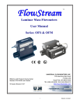
Do not mistake the direction of the surge absorbing diode installed on the DC relay for the control
signal output of brake signals, etc. Incorrect installation may lead to signals not being output
when trouble occurs or the protective functions not functioning.
Servo amplifier
DOCOM
Control output
signal
Servo amplifier
24VDC
DOCOM
Control output
signal
RA
DICOM
24VDC
RA
DICOM
For the sink output interface
For the source output interface
Do not connect or disconnect the connection cables between each unit, the encoder cable or
PLC expansion cable while the power is ON.
Securely tighten the cable connector fixing screws and fixing mechanisms. Insufficient fixing may
lead to the cables combing off during operation.
Do not bundle the power line or cables.
(5) Trial operation and adjustment
CAUTION
Confirm and adjust the program and each parameter before operation. Unpredictable
movements may occur depending on the machine.
Extreme adjustments and changes may lead to unstable operation, so never make them.
When using the absolute position system function, on starting up, and when the Motion controller
or absolute value motor has been replaced, always perform a home position return.
Before starting test operation, set the parameter speed limit value to the slowest value, and
make sure that operation can be stopped immediately by the forced stop, etc. if a hazardous
state occurs.
A-7
(6) Usage methods
CAUTION
Immediately turn OFF the power if smoke, abnormal sounds or odors are emitted from the
Motion controller, servo amplifier or servomotor.
Always execute a test operation before starting actual operations after the program or
parameters have been changed or after maintenance and inspection.
Do not attempt to disassemble and repair the units excluding a qualified technician whom our
company recognized.
Do not make any modifications to the unit.
Keep the effect or electromagnetic obstacles to a minimum by installing a noise filter or by using
wire shields, etc. Electromagnetic obstacles may affect the electronic devices used near the
Motion controller or servo amplifier.
When using the CE Mark-compliant equipment, refer to the User's manual for the Motion
controllers and refer to the corresponding EMC guideline information for the servo amplifiers,
inverters and other equipment.
Use the units with the following conditions.
Item
Conditions
Input power
According to each instruction manual.
Input frequency
According to each instruction manual.
Tolerable momentary power failure
According to each instruction manual.
(7) Corrective actions for errors
CAUTION
If an error occurs in the self diagnosis of the Motion controller or servo amplifier, confirm the
check details according to the instruction manual, and restore the operation.
If a dangerous state is predicted in case of a power failure or product failure, use a servomotor
with electromagnetic brakes or install a brake mechanism externally.
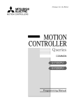
Use a double circuit construction so that the electromagnetic brake operation circuit can be
operated by emergency stop signals set externally.
Shut off with servo ON signal OFF,
alarm, electromagnetic brake signal.
Servo motor
RA1
Electromagnetic
B
brakes
Shut off with the
emergency stop
signal (EMG).
EMG
24VDC
If an error occurs, remove the cause, secure the safety and then resume operation after alarm
release.
The unit may suddenly resume operation after a power failure is restored, so do not go near the
machine. (Design the machine so that personal safety can be ensured even if the machine
restarts suddenly.)
A-8
(8) Maintenance, inspection and part replacement
CAUTION
Perform the daily and periodic inspections according to the instruction manual.
Perform maintenance and inspection after backing up the program and parameters for the Motion
controller and servo amplifier.
Do not place fingers or hands in the clearance when opening or closing any opening.
Periodically replace consumable parts such as batteries according to the instruction manual.
Do not touch the lead sections such as ICs or the connector contacts.
Before touching the module, always touch grounded metal, etc. to discharge static electricity from
human body. Failure to do so may cause the module to fail or malfunction.
Do not directly touch the module's conductive parts and electronic components.
Touching them could cause an operation failure or give damage to the module.
Do not place the Motion controller or servo amplifier on metal that may cause a power leakage
or wood, plastic or vinyl that may cause static electricity buildup.
Do not perform a megger test (insulation resistance measurement) during inspection.
When replacing the Motion controller or servo amplifier, always set the new module settings
correctly.
When the Motion controller or absolute value motor has been replaced, carry out a home
position return operation using one of the following methods, otherwise position displacement
could occur.
1) After writing the servo data to the Motion controller using programming software, switch on the
power again, then perform a home position return operation.
2) Using the backup function of the programming software, load the data backed up before
replacement.
After maintenance and inspections are completed, confirm that the position detection of the
absolute position detector function is correct.
Do not drop or impact the battery installed to the module.
Doing so may damage the battery, causing battery liquid to leak in the battery. Do not use the
dropped or impacted battery, but dispose of it.
Do not short circuit, charge, overheat, incinerate or disassemble the batteries.
The electrolytic capacitor will generate gas during a fault, so do not place your face near the
Motion controller or servo amplifier.
The electrolytic capacitor and fan will deteriorate. Periodically replace these to prevent secondary
damage from faults. Replacements can be made by our sales representative.
Lock the control panel and prevent access to those who are not certified to handle or install
electric equipment.
Do not burn or break a module and servo amplifier. Doing so may cause a toxic gas.
A-9
(9) About processing of waste
When you discard Motion controller, servo amplifier, a battery (primary battery) and other option
articles, please follow the law of each country (area).
CAUTION
This product is not designed or manufactured to be used in equipment or systems in situations
that can affect or endanger human life.
When considering this product for operation in special applications such as machinery or systems
used in passenger transportation, medical, aerospace, atomic power, electric power, or
submarine repeating applications, please contact your nearest Mitsubishi sales representative.
Although this product was manufactured under conditions of strict quality control, you are strongly
advised to install safety devices to forestall serious accidents when it is used in facilities where a
breakdown in the product is likely to cause a serious accident.
(10) General cautions
All drawings provided in the instruction manual show the state with the covers and safety
partitions removed to explain detailed sections. When operating the product, always return the
covers and partitions to the designated positions, and operate according to the instruction
manual.
A - 10
REVISIONS
The manual number is given on the bottom left of the back cover.
Print Date
May., 2012
Jan., 2015
Manual Number
Revision
IB(NA)-0300183-A First edition
IB(NA)-0300183-B Revisions regarding the addition of safety communication function and
safety encoder
[Additional correction/partial correction]
Chapter 1, section 1.1, section1.2, section 1.3, section 1.4.2, section
1.4.5, section 1.5, section 1.6, section 2.1, section 2.2, section 2.4.1,
section 2.7.1, section 3.4.1, section 3.4.2, section 3.5.1, section 4.1,
section 4.2, section 4.3.2, section 6.1, section 6.2, section 6.4
[Additional]
Section 1.4.7, section 2.9, section 2.9.1, section 2.9.2, section 2.9.3,
section 2.9.4, section 2.9.5, section 2.9.6, section 2.11, section 4.3.5,
section 4.3.6
Japanese Manual Number IB(NA)-0300182
This manual confers no industrial property rights or any rights of any other kind, nor does it confer any patent
licenses. Mitsubishi Electric Corporation cannot be held responsible for any problems involving industrial property
rights which may occur as a result of using the contents noted in this manual.
© 2012 MITSUBISHI ELECTRIC CORPORATION
A - 11
INTRODUCTION
Thank you for choosing the Mitsubishi Motion controller Q173D(S)CPU/Q172D(S)CPU.
Before using the equipment, please read this manual carefully to develop full familiarity with the functions
and performance of the Motion controller you have purchased, so as to ensure correct use.
CONTENTS
Safety Precautions .........................................................................................................................................A- 1
Revisions ........................................................................................................................................................A-11
Contents .........................................................................................................................................................A-12
About Manuals ...............................................................................................................................................A-16
Manual Page Organization ............................................................................................................................A-18
1. OVERVIEW
1- 1 to 1-20
1.1 Functional Overview ................................................................................................................................ 1- 3
1.2 System Configuration............................................................................................................................... 1- 5
1.2.1 Q173DSXY Safety signal module..................................................................................................... 1- 8
1.3 Applicable Standard ................................................................................................................................. 1- 9
1.4 Risk Assessment...................................................................................................................................... 1-10
1.4.1 Safety signal comparison .................................................................................................................. 1-11
1.4.2 Speed monitoring function (SLS) ...................................................................................................... 1-11
1.4.3 Safe speed monitor (SSM)................................................................................................................ 1-12
1.4.4 Shut-off function (STO, SS1) ............................................................................................................ 1-13
1.4.5 Standstill monitoring (SOS, SS2) ..................................................................................................... 1-14
1.4.6 Safe break control (SBC) .................................................................................................................. 1-14
1.4.7 Safety communication function ......................................................................................................... 1-15
1.5 Restrictions ............................................................................................................................................... 1-16
1.6 Equipment Configuration of Safety Observation Function Compatible Motion Controller .................... 1-18
2. SAFETY OBSERVATION FUNCTION
2- 1 to 2-46
2.1 Configuration of Safety Observation Function ........................................................................................ 2- 1
2.2 Sequence Programs for Safety Observation on PLC CPU .................................................................... 2- 3
2.2.1 Activity check in sequence programs for safety observation ........................................................... 2- 6
2.3 Safety Signals Comparison ..................................................................................................................... 2- 7
2.3.1 Re-start after error ............................................................................................................................. 2- 7
2.4 Speed Monitoring Function (SLS) ........................................................................................................... 2- 8
2.4.1 System configuration of speed monitoring function ......................................................................... 2- 8
2.4.2 Timing of speed monitoring function................................................................................................. 2-12
2.4.3 Example of speed monitoring start operation................................................................................... 2-13
2.4.4 Parameter consistency check ........................................................................................................... 2-14
2.4.5 Comparison of speed monitoring parameter .................................................................................... 2-14
2.4.6 Speed command observation ........................................................................................................... 2-14
2.4.7 Feedback speed observation............................................................................................................ 2-15
2.4.8 Position feedback monitoring............................................................................................................ 2-15
2.4.9 Speed deviation monitoring .............................................................................................................. 2-16
2.4.10 External auxiliary pulse input observation ...................................................................................... 2-17
2.4.11 Continuous standstill during speed monitoring .............................................................................. 2-17
A - 12
2.4.12 Speed error detection check ........................................................................................................... 2-17
2.5 Safe Speed Monitor (SSM) ...................................................................................................................... 2-18
2.6 Shut-off Function (STO/SS1) ................................................................................................................... 2-19
2.6.1 Sequence program example for shut-off function (STO/SS1 (Stop category 1)) ........................... 2-19
2.7 Standstill Monitoring (SOS, SS2) ............................................................................................................ 2-21
2.7.1 Encoder consistency check by small oscillation during standstill monitoring ................................. 2-21
2.7.2 Sequence program example for standstill monitoring (SOS, SS2 (Stop category 2)) .................... 2-23
2.7.3 Sequence program example for small oscillation during standstill monitoring ............................... 2-24
2.8 Safe Break Control (SBC)........................................................................................................................ 2-26
2.8.1 Sequence program example for safe break control (SBC).............................................................. 2-26
2.9 Safety Communication ............................................................................................................................. 2-27
2.9.1 Functional safety signal..................................................................................................................... 2-30
2.9.2 Sequence program example for shut-off function (STO, SS1 (Stop category 1)) .......................... 2-33
2.9.3 Sequence program example for standstill monitoring (SOS, SS2 (Stop category 2)) .................... 2-35
2.9.4 Sequence program example for speed monitoring (SLS1 to SLS4) ............................................... 2-37
2.9.5 Checking the connection status of safety communication ............................................................... 2-39
2.9.6 SSCNET communication condition monitor .................................................................................. 2-40
2.10 Self-diagnosis Function ......................................................................................................................... 2-41
2.10.1 Safety signal output check function ................................................................................................ 2-41
2.10.2 Memory Check Function ................................................................................................................. 2-43
2.10.3 Internal processing check of Safety observation function ............................................................. 2-43
2.10.4 Scan time check .............................................................................................................................. 2-44
2.10.5 Voltage monitoring of Motion CPU circuit ...................................................................................... 2-44
2.10.6 Temperature monitoring of Motion CPU module ........................................................................... 2-44
2.11 Speed Monitoring Function Omitting External Auxiliary Pulse Input .................................................. 2-45
3. START-UP PROCEDURES
3- 1 to 3-30
3.1 Start-up Procedures Flow Chart .............................................................................................................. 3- 1
3.2 Communication between GX Works2/GX Developer and Motion CPU................................................. 3- 3
3.3 PLC Memory Formating ........................................................................................................................... 3- 4
3.4 Parameters Setting .................................................................................................................................. 3- 5
3.4.1 Parameter setting of Motion CPU ..................................................................................................... 3- 5
3.4.2 Parameter settings for PLC CPU...................................................................................................... 3-11
3.5 Creating User Safety Sequence Program ............................................................................................... 3-17
3.5.1 Creating PLC CPU side user safety sequence program ................................................................. 3-17
3.5.2 Creating Motion CPU side user safety sequence program ............................................................. 3-19
3.6 Validation of Parameter or Program ........................................................................................................ 3-29
3.6.1 How to validate parameter ................................................................................................................ 3-29
3.6.2 How to validate user safety sequence program ............................................................................... 3-30
4. DEDICATED DEVICES
4- 1 to 4-28
4.1 Special Relay/Special Register for Safety Observation Function .......................................................... 4- 1
4.2 Device Used in Sequence Programs for Safety Observation on PLC CPU Side.................................. 4- 3
4.3 Multiple CPU Shared Device for Safety Observation Functions ............................................................ 4- 4
4.3.1 Shared device list for safety signal comparison ............................................................................... 4- 5
4.3.2 Detailed description of shared device for safety signal comparison ............................................... 4- 6
4.3.3 Shared device list for speed monitoring ........................................................................................... 4-13
4.3.4 Detailed description of shared device for speed monitoring ............................................................ 4-14
A - 13
4.3.5 Shared device list for safety communication .................................................................................... 4-21
4.3.6 Detailed description of shared device for safety communication .................................................... 4-22
5. SEQUENCE INSTRUCTIONS FOR MOTION CPU
5- 1 to 5-78
5.1 Description of the Device for the Sequence Program ............................................................................ 5- 1
5.1.1 Input/output (X, Y) ............................................................................................................................. 5- 1
5.1.2 Internal relays (M, F) ......................................................................................................................... 5- 2
5.1.3 Special relays (SM) ........................................................................................................................... 5- 3
5.1.4 Timer (T) ............................................................................................................................................ 5- 3
5.1.5 Counter (C) ........................................................................................................................................ 5- 5
5.1.6 Data register (D) ................................................................................................................................ 5- 5
5.1.7 Link register (W) ................................................................................................................................ 5- 6
5.1.8 Index registers (Z) ............................................................................................................................. 5- 6
5.1.9 Nesting (N) ........................................................................................................................................ 5- 7
5.1.10 Pointer (P) ....................................................................................................................................... 5- 8
5.1.11 Special register (SD) ....................................................................................................................... 5- 8
5.1.12 Decimal constant (K) ....................................................................................................................... 5- 9
5.1.13 Hexadecimal constant (H)............................................................................................................... 5- 9
5.2 Configuration of Instructions .................................................................................................................... 5-10
5.2.1 How to read the instruction table ...................................................................................................... 5-10
5.2.2 Number of steps ................................................................................................................................ 5-11
5.2.3 END instruction ................................................................................................................................. 5-12
5.2.4 Index ornament ................................................................................................................................. 5-12
5.2.5 Digit designation ................................................................................................................................ 5-13
5.3 Basic Instructions ..................................................................................................................................... 5-16
5.3.1 Operation start, series connection, parallel connection: LD, LDI, AND, ANI, OR, ORI .................. 5-16
5.3.2 Ladder block series connection and parallel connection: ANB, ORB ............................................. 5-17
5.3.3 Out instruction: OUT (excluding timers, counters) ........................................................................... 5-18
5.3.4 Timers: OUT T................................................................................................................................... 5-19
5.3.5 Counter: OUT C ................................................................................................................................ 5-21
5.3.6 Setting and resetting devices: SET, RST ......................................................................................... 5-22
5.3.7 Setting and resetting the master control: MC, MCR ........................................................................ 5-23
5.3.8 Leading edge and trailing edge outputs: PLS, PLF ......................................................................... 5-25
5.3.9 Bit device shifts: SFT ........................................................................................................................ 5-26
5.3.10 Operation results push, read, pop: MPS, MRD, MPP ................................................................... 5-27
5.4 Function Instructions ................................................................................................................................ 5-28
5.4.1 16-bit data comparisons: =, <, > ....................................................................................................... 5-28
5.4.2 32-bit data comparisons: D=, D<, D> ............................................................................................... 5-29
5.4.3 BIN 16-bit addition and subtraction operations: +, -......................................................................... 5-30
5.4.4 BIN 32-bit addition and subtraction operations: D+, D- ................................................................... 5-32
5.4.5 BIN 16-bit multiplication and division operations: *, / ....................................................................... 5-34
5.4.6 BIN 32-bit multiplication and division operations: D*, D/.................................................................. 5-36
5.4.7 Incrementing and decrementing 16-bit BIN data: INC, DEC ........................................................... 5-38
5.4.8 Incrementing and decrementing 32-bit BIN data: DINC, DDEC...................................................... 5-39
5.4.9 Conversion from BIN to BCD (16 bits, 32bits): BCD, DBCD ........................................................... 5-40
5.4.10 Conversion from BCD to BIN (16 bits, 32bits): BIN, DBIN ............................................................ 5-42
5.4.11 16-bit and 32-bit data transfers: MOV, DMOV ............................................................................... 5-44
5.4.12 16-bit and 32-bit data exchanges: XCH, DXCH ............................................................................. 5-45
A - 14
5.4.13 Block 16-bit data transfers: BMOV ................................................................................................. 5-46
5.4.14 Identical 16-bit data block transfers: FMOV ................................................................................... 5-47
5.4.15 Pointer branch instructions: CJ ....................................................................................................... 5-48
5.4.16 End main routine program: FEND .................................................................................................. 5-50
5.4.17 Call/return of subroutine program: CALL, RET .............................................................................. 5-51
5.4.18 Logical products with 16-bit data: WAND....................................................................................... 5-52
5.4.19 Logical product with 32-bit data: DAND ......................................................................................... 5-53
5.4.20 Logical sums with 16-bit data: WOR .............................................................................................. 5-54
5.4.21 Logical sum with 32-bit data: DOR ................................................................................................. 5-55
5.4.22 16-bit exclusive OR operation: WXOR ........................................................................................... 5-56
5.4.23 32-bit exclusive OR operation: DXOR ............................................................................................ 5-57
5.4.24 Complement of 2 of BIN 16-bit data: NEG ..................................................................................... 5-58
5.4.25 Right rotation of 16-bit data: ROR, RCR ........................................................................................ 5-59
5.4.26 Right rotation of 32-bit data: DROR, DRCR ................................................................................... 5-61
5.4.27 Left rotation of 16-bit data: ROL, RCL ............................................................................................ 5-63
5.4.28 Left rotation of 32-bit data: DROL, DRCL ...................................................................................... 5-65
5.4.29 n-bit shift to right or left of 16-bit data: SFR, SFL ........................................................................... 5-67
5.4.30 1-word shift to right or left of n-word data: DSFR, DSFL ............................................................... 5-69
5.4.31 16-bit data searches: SER .............................................................................................................. 5-71
5.4.32 16-bit data checks: SUM ................................................................................................................. 5-72
5.4.33 Decoding from 8 to 256 bits: DECO ............................................................................................... 5-73
5.4.34 7-segment decode: SEG ................................................................................................................ 5-75
5.4.35 Calculation of average value: S.AVE ............................................................................................. 5-77
6. TROUBLESHOOTING
6- 1 to 6-14
6.1 Safety Observation Error List................................................................................................................... 6- 1
6.2 Safety Observation Warning List ............................................................................................................. 6- 8
6.3 How to Correct Errors of Motion CPU Side Sequence Program ............................................................ 6-10
6.4 Troubleshooting when the Error "CAN'T EXE. PRG" Occurs in a PLC CPU ........................................ 6-13
APPENDICES
App- 1 to App-14
APPENDIX 1 Functions of GX Works2/GX Developer available for Motion CPU ...................................App- 1
APPENDIX 1.1 GX Works2 features support........................................................................................App- 1
APPENDIX 1.2 GX Developer features support ...................................................................................App- 8
APPENDIX 2 Example of Checklist for User Documentation ................................................................. App-14
A - 15
About Manuals
The following manuals are also related to this product.
In necessary, order them by quoting the details in the tables below.
Related Manuals
(1) Motion controller
Manual Number
(Model Code)
Manual Name
Q173D(S)CPU/Q172D(S)CPU Motion controller User's Manual
This manual explains specifications of the Motion CPU modules, Q172DLX Servo external signal interface
module, Q172DEX Synchronous encoder interface module, Q173DPX Manual pulse generator interface
module, Power supply modules, Servo amplifiers, SSCNET
IB-0300133
(1XB927)
cables and Synchronous encoder, and the
maintenance/inspection for the system, trouble shooting and others.
Q173D(S)CPU/Q172D(S)CPU Motion controller Programming Manual (COMMON)
This manual explains the Multiple CPU system configuration, performance specifications, common
IB-0300134
(1XB928)
parameters, auxiliary/applied functions, error lists and others.
Q173D(S)CPU/Q172D(S)CPU Motion controller (SV13/SV22) Programming Manual
(Motion SFC)
This manual explains the functions, programming, debugging, error lists for Motion SFC and others.
Q173D(S)CPU/Q172D(S)CPU Motion controller (SV13/SV22) Programming Manual
(REAL MODE)
This manual explains the servo parameters, positioning instructions, device lists, error lists and others.
Q173D(S)CPU/Q172D(S)CPU Motion controller (SV22) Programming Manual
(VIRTUAL MODE)
This manual explains the dedicated instructions to use the synchronous control by virtual main shaft,
mechanical system program create mechanical module, servo parameters, positioning instructions, device
IB-0300135
(1XB929)
IB-0300136
(1XB930)
IB-0300137
(1XB931)
lists, error lists and others.
Q173DSCPU/Q172DSCPU Motion controller (SV22) Programming Manual
(Advanced Synchronous Control)
This manual explains the dedicated instructions to use the synchronous control by synchronous control
IB-0300198
(1XB953)
parameters, device lists, error lists and others.
Q173D(S)CPU/Q172D(S)CPU Motion controller Programming Manual (Safety Observation)
This manual explains the details, safety parameters, safety sequence program instructions, device lists
IB-0300183
(1XB945)
and error lists and others for safety observation function by Motion controller.
Motion controller Setup Guidance (MT Developer2 Version1)
This manual explains the items related to the setup of the Motion controller programming software
MT Developer2.
A - 16
IB-0300142
( — )
(2) PLC
Manual Number
(Model Code)
Manual Name
QCPU User's Manual (Hardware Design, Maintenance and Inspection)
This manual explains the specifications of the QCPU modules, power supply modules, base units,
extension cables, memory card battery, and the maintenance/inspection for the system, trouble shooting,
SH-080483ENG
(13JR73)
error codes and others.
QnUCPU User's Manual (Function Explanation, Program Fundamentals)
This manual explains the functions, programming methods and devices and others to create programs
SH-080807ENG
(13JZ27)
with the QCPU.
QCPU User's Manual (Multiple CPU System)
This manual explains the Multiple CPU system overview, system configuration, I/O modules,
communication between CPU modules and communication with the I/O modules or intelligent function
SH-080485ENG
(13JR75)
modules.
QnUCPU User's Manual (Communication via Built-in Ethernet Port)
This manual explains functions for the communication via built-in Ethernet port of the CPU module.
MELSEC-Q/L Programming Manual (Common Instruction)
This manual explains how to use the sequence instructions, basic instructions, application instructions and
SH-080811ENG
(13JZ29)
SH-080809ENG
(13JW10)
micro computer program.
MELSEC-Q/L/QnA Programming Manual (PID Control Instructions)
This manual explains the dedicated instructions used to exercise PID control.
MELSEC-Q/L/QnA Programming Manual (SFC)
This manual explains the system configuration, performance specifications, functions, programming,
SH-080040
(13JF59)
SH-080041
(13JF60)
debugging, error codes and others of MELSAP3.
I/O Module Type Building Block User's Manual
This manual explains the specifications of the I/O modules, connector, connector/terminal block
SH-080042
(13JL99)
conversion modules and others.
MELSEC-L SSCNET /H Head Module User's Manual
This manual explains specifications of the head module, procedures before operation, system
configuration, installation, wiring, settings, and troubleshooting.
A - 17
SH-081152ENG
(13JZ78)
(3) Servo amplifier
Manual Number
(Model Code)
Manual Name
SSCNET /H interface AC Servo MR-J4_B(-RJ)/MR-J4_B4(-RJ)/MR-J4_B1(-RJ) Servo
amplifier Instruction Manual
This manual explains the I/O signals, parts names, parameters, start-up procedure and others for AC
SH-030106
(1CW805)
Servo MR-J4_B(-RJ)/MR-J4_B4(-RJ)/MR-J4_B1(-RJ) MR-J4- B Servo amplifier.
SSCNET /H interface Multi-axis AC Servo MR-J4W2-_B/MR-J4W3-_B Servo amplifier
Instruction Manual
This manual explains the I/O signals, parts names, parameters, start-up procedure and others for Multi-
SH-030105
(1CW806)
axis AC Servo MR-J4W2-_B/MR-J4W3-_B Servo amplifier.
Functional safety unit MR-D30 Instruction Manual
This manual explains the I/O signals, parts names, parameters, start-up procedure and others for
SH-030132
(1CW817)
functional safety unit MR-D30.
SSCNET
interface MR-J3- B Servo amplifier Instruction Manual
This manual explains the I/O signals, parts names, parameters, start-up procedure and others for
SH-030051
(1CW202)
MR-J3- B Servo amplifier.
SSCNET
Compatible Linear Servo MR-J3- B-RJ004U
Instruction Manual
This manual explains the I/O signals, parts names, parameters, start-up procedure and others for Linear
Servo MR-J3- B-RJ004U
SH-030054
(1CW943)
Servo amplifier.
SSCNET Compatible Fully Closed Loop Control MR-J3- B-RJ006 Servo amplifier
Instruction Manual
This manual explains the I/O signals, parts names, parameters, start-up procedure and others for Fully
SH-030056
(1CW304)
Closed Loop Control MR-J3- B-RJ006 Servo amplifier.
SSCNET interface 2-axis AC Servo Amplifier MR-J3W-0303BN6/MR-J3W- B Servo
amplifier Instruction Manual
This manual explains the I/O signals, parts names, parameters, start-up procedure and others for 2-axis
SH-030073
(1CW604)
AC Servo Amplifier MR-J3W-0303BN6/MR-J3W- B Servo amplifier.
SSCNET
Manual
Interface Direct Drive Servo MR-J3- B-RJ080W Servo amplifier Instruction
This manual explains the I/O signals, parts names, parameters, start-up procedure and others for Direct
SH-030079
(1CW601)
Drive Servo MR-J3- B-RJ080W Servo amplifier.
SSCNET
Manual
interface Drive Safety integrated MR-J3- B Safety Servo amplifier Instruction
This manual explains the I/O signals, parts names, parameters, start-up procedure and others for safety
SH-030084
(1CW205)
integrated MR-J3- B Safety Servo amplifier.
Manual Page Organization
The symbols used in this manual are shown below.
Symbol
QDS
QD
Description
Symbol that indicates correspondence to only Q173DSCPU/Q172DSCPU.
Symbol that indicates correspondence to only Q173DCPU-S1/Q172DCPU-S1.
A - 18
1 OVERVIEW
1. OVERVIEW
This manual describes the safety observation function and start-up procedure in
Motion controller, and the devices and instructions for creating a sequence program for
the safety circuit.
In this manual, the following abbreviations are used.
Generic term/Abbreviation
Description
Motion CPU built-in safety observation
Q173DSCPU/Q172DSCPU/Q173DCPU-S1/Q172DCPU-S1 Motion CPU module
(module) or Motion CPU (module)
Q173DSXY Safety signal module
Safety signal module
AMP or Servo amplifier
General name for "Servo amplifier model MR-J4- B/MR-J4W- B MR-J3- B/
MR-J3W- B"
QCPU, PLC CPU or PLC CPU module QnUD(E)(H)CPU
Multiple CPU system or Motion system Abbreviation for "Multiple PLC system of the Q series"
Operating system software
General name for "SW8DNC-SV13Q /SW8DNC-SV22Q "
Programming software package
General name for MT Developer2/GX Works2/GX Developer/MR Configurator
Abbreviation for "Motion controller engineering environment
MELSOFT MT Works2"
Abbreviation for "Motion controller programming software MT Developer2
(Version 1.34L or later)"
Abbreviation for "Programmable controller engineering software
MELSOFT GX Works2 (Version 1.15R or later)"
Abbreviation for "MELSEC PLC programming software package
GX Developer (Version 8.48A or later)"
MELSOFT MT Works2
MT Developer2
(Note-1)
GX Works2
GX Developer
SSCNET /H
SSCNET
(Note-2)
(Note-2)
SSCNET (/H)
(Note-2)
High speed synchronous network between Motion controller and servo amplifier
General name for SSCNET /H, SSCNET
Multiple CPU high speed transmission Dedicated bus communication between PLC CPU and Motion CPU
Communication between PLC CPU and safety signal module via base unit
Bus transmission
RIO transmission
Serial communication between Motion CPU and Safety signal module
Safety signal
User safety sequence program
I/O signal in the safety circuit such as such safety door signal and light curtain
User sequence program for I/O control of the safety signal
User program
General name for user sequence program or Motion control program
Safety signal comparison sequence
program
Program for PLC CPU to compare safety signal
(Automatically created by Motion CPU.)
Speed monitoring sequence program
Program for PLC CPU to execute the speed monitoring
(Automatically created by Motion CPU.)
Sequence programs for safety
observation
General name for "Safety signal comparison sequence program" and "Speed
monitoring sequence program"
SLS
(Note-3)
Abbreviation for Safely-limited Speed.
SSM
(Note-3)
Abbreviation for Safe Speed Monitor.
STO
(Note-3)
Abbreviation for Safe torque off that shuts off servo amplifier main circuit power
(primary contactor), or electronically shuts off power the servo motor within the
servo amplifier
Shut-off
(Note-3)
Abbreviation for Safe stop 1
(Note-3)
Abbreviation for Safe operating stop
SS2
(Note-3)
Abbreviation for Safe stop 2
SBC
(Note-3)
Abbreviation for Safe brake control
SS1
SOS
1-1
1
1 OVERVIEW
Generic term/Abbreviation
Description
Safety signal input pulse for double feedback during speed monitoring
Diagnostic function to check the consistency between the encoder feedback value
and auxiliary pulse
Function for communicating safety data between safety stations on the same
network.
Encoder that is installed in a safety standard compatible motor.
External auxiliary pulse input
Small oscillation
Safety communication
Safety encoder
(Note-1): This software is included in Motion controller engineering environment "MELSOFT MT Works2".
(Note-2): SSCNET: Servo System Controller NETwork
(Note-3): Function that are defined in IEC 61800-5-2
REMARK
For information about each module, design method for program and parameter, refer
to the following manuals relevant to each module.
Item
Reference Manual
Q173D(S)CPU/Q172D(S)CPU Motion controller User's
Motion CPU module/Motion unit
Manual
PLC CPU, peripheral devices for sequence program design,
I/O modules and intelligent function module
Operation method for MT Developer2
Manual relevant to each module
Help of each software
• Multiple CPU system configuration
• Performance specification
Q173D(S)CPU/Q172D(S)CPU Motion controller
• Design method for common parameter
Programming Manual (COMMON)
• Auxiliary and applied functions (common)
• Design method for Motion SFC program
SV13/SV22
• Design method for Motion SFC parameter
• Motion dedicated PLC instruction
Q173D(S)CPU/Q172D(S)CPU Motion controller
(SV13/SV22) Programming Manual (Motion SFC)
• Design method for positioning control
program in the real mode
• Design method for positioning control
Q173D(S)CPU/Q172D(S)CPU Motion controller
(SV13/SV22) Programming Manual (REAL MODE)
parameter
SV22
(Virtual mode)
• Design method for mechanical system
program
Q173D(S)CPU/Q172D(S)CPU Motion controller (SV22)
Programming Manual (VIRTUAL MODE)
SV22
(Advanced
synchronous
• Design method for synchronous control
parameter
Q173DSCPU/Q172DSCPU Motion controller (SV22)
Programming Manual (Advanced Synchronous Control)
control)
1-2
1 OVERVIEW
1.1 Functional Overview
Motion controller has safety observation functions such as safety signal comparison,
speed monitoring function, safe speed monitor, shut-off function, standstill monitoring,
and safe brake control in addition to the general purpose Motion control functions.
Furthermore, for Motion CPUs that support safety communication function, a safety
communication compatible servo amplifier and safety encoder may be included in the
system.
All the safety of human lives and properties are not guaranteed by these functions.
Execute risk assessment by user and reduce the level of risk until the residual risk is
less than the tolerable risk.
• Safety signal comparison
A safety signal is input/output to/from PLC CPU and Motion CPU. The CPUs
compare the safety signals. The power will be shut off if error occurs.
• Speed monitoring function (SLS)
PLC CPU and Motion CPU monitor if the motor speed does not exceed the safety
speed. The power will be shut off if error occurs.
• Safe speed monitor (SSM)
SSM outputs the safety signal indicating the motor speed is safety speed or lower.
• Shut-off function (STO, SS1)
This function is composed of SS1 and STO. SS1 function initiates the motor
deceleration and initiates the STO function after an application specific time delay.
STO function shuts power to the motor.
• Standstill monitoring (SOS, SS2)
This function is composed of SOS and SS2. SS2 function initiates the motor
deceleration and initiates the STO function after an application specific time delay.
SOS function monitors if the motor stand still while power is being supplied.
• Safe brake control (SBC)
Two control signals for holding the motor by brake are output.
• Safety communication function QDS
Communicates safety information with the servo amplifier by using the safety
communication function in a system compatible with safety communication.
Also checks the operation and status of safety observation functions in the servo
amplifier with the safety sequence program of the user.
Speed monitoring function and standstill monitoring can be performed using a safety
encoder.
(1) Correspondence table for function name of EN standards and safety observation
function in a Motion system.
Abbreviation
SLS
Function name
EN 61800-5-2
Motion system
Safely-limited Speed
Speed monitoring function
SSM
Safe Speed Monitor
Safe speed monitor
STO
Safe Torque Off
SS1
Safe Stop 1
SOS
Safe Operating Stop
SS2
Safe Stop 2
SBC
Safe Brake Control
1-3
Shut-off function
Standstill monitoring
Safe brake control
1 OVERVIEW
(2) Safety specification
Item
Specification
Category
Category3 (EN ISO13849-1)
Safety Integrity Level
SIL CL2 (EN62061)
Performance Level
PL d (EN ISO13849-1)
MTTFd
169 years or longer
DC
Low
2.17×10
PFH
-8
hr
-1
Safety signal comparison,
Safety observation
safety communication (IEC61784-3:2010),
functions
STO,SS1,SS2,SOS,SLS,SBC,SSM (IEC61800-5-2:2007)
(Note): Safety specifications are under certificate. Above description is the minimum value
required for certification. After certified, the value will be updated.
Only processing block is included in the scope of safety specifications. Input block
(including sensor) and output block (contactor and safety servo STO function) are
not included.
PLC CPU
Motion CPU
Safety signal
comparison
Safety signal
comparison
Speed monitoring
function
Safe speed monitor
Multiple CPU
high speed
transmission
Speed monitoring
function
Safe speed monitor
Shut-off function
Shut-off function
Standstill monitoring
Standstill monitoring
Safe brake control
Safe brake control
Main power
When servo amplifier without
STO function is used, shut main
power by magnet contactor.
MC
MC
Bus transmission
RIO transmission
Safety signal module
Safety signal: Safety door switch, Light curtain
Emergency stop input, External
auxiliary pulse speed monitoring etc.
SSCNET (/H)
Motor encoder
position feedback
Shut-off (via Motion CPU)
STO
Shut-off (via PLC CPU)
STO
SSCNET (/H)
Motor encoder position
Functional safety
feedback
Functional safety status command
Servo motor/
safety encoder or
standard encoder
1-4
Servo amplifier
Servo motor/
standard encoder
Safety
communication
compatible
servo amplifier
Servo motor/
safety encoder or
standard encoder
1 OVERVIEW
1.2 System Configuration
Safety observation function is configured by Motion CPU built-in safety observation
(Q17 DSCPU/Q17 DCPU-S1), PLC CPU and safety signal module (Q173DSXY).
Wire two signals to the safety signal module for PLC CPU and Motion CPU. The safety
observation is executed in the Motion CPU and PLC CPU individually.
The speed monitoring function monitors both the command speed and feedback speed.
It also uses external auxiliary pulses to ensure safety when the motor is stopped.
When performing speed monitoring function with a safety encoder compatible Motion
CPU and safety encoder compatible servo amplifier, external auxiliary pulse input is
not necessary.
Refer to "Functional safety unit MR-D30 Instruction Manual" for details of safety
communication function compatible servo amplifiers and safety encoder compatible
servo amplifiers.
Only one PLC CPU (CPU No.1) and one Motion CPU (CPU No.2) execute safety
observation. The other CPUs (CPU No.3 or later) cannot execute safety observation.
1-5
1 OVERVIEW
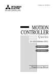
The diagram below shows the system configuration for safety observation function.
Main base
Q3 DB
PLC
CPU
QnUD
CPU
Motion
CPU Safety
built-in signal
safety module
obser- Q173
vation DSXY
Power
supply
Q6 P
Main power
USB/RS-232/
Ethernet
Ethernet
RIO
cable
I/O cable
MC
SSCNET (/H)
MC
GX Works2/GX Developer
MT Developer2
Terminal block
(Motion CPU)
Terminal block
(PLC CPU)
Shut-off
STO
Shut-off
STO
When using
servo amplifier
without a STO
function
Servo amplifier
External auxiliary pulses
Mechanical attachment
Emergency stop Safety door
switch
switch
Light curtain
SSCNET (/H)
Servo motor/
standard encoder
Safety
communication
compatible
servo amplifier
Servo motor/
safety encoder
or standard
encoder (Note-1)
(Note-1): When performing standstill monitoring, an external auxiliary pulse generator is required.
1-6
1 OVERVIEW
System combinations that support safety observation function, and the safety
observation functions that can be applied by the Motion CPU are shown below.
Motion CPU
Servo amplifier
Safety observation function
Encoder
STO
SS1
SS2
SOS
SLS
SBC
SSM
Standard encoder
Not safety encoder
compatible
Standard encoder and
external auxiliary pulse
Safety encoder
Not safety encoder
(Note-1)
compatible
(Note-2)
Standard encoder
Safety encoder
compatible
Standard encoder and
external auxiliary pulse
Safety encoder
Standard encoder
Not safety encoder
(Note-1)
compatible
Standard encoder and
external auxiliary pulse
Safety encoder
Safety encoder
compatible
(Note-2)
Standard encoder
Safety encoder
compatible
Standard encoder and
external auxiliary pulse
Safety encoder
: Can be applied
: Cannot be applied
(Note-1): Assumed as safety communication function compatible.
(Note-2): When a safety encoder is connected to a servo amplifier not compatible with safety encoders, the safety encoder functions as a
standard encoder.
1-7
1 OVERVIEW
1.2.1 Q173DSXY Safety signal module
The safety signal module is the I/O combined module that has 20 input points ×2 lines
and 12 output points ×2 lines. (Number of occupied I/O points: 32 points per slot)
Up to three safety signal modules can be used. The safety signal module cannot be
used on the extension base unit.
One output point is controlled by the system as a shut-off signal. (Safety observation is
normal: ON, abnormal: OFF)
Communication method is the following:
• Bus communication between safety signal module and PLC CPU
• Remote I/O communication between safety signal module and Motion CPU
Refer to the "Q173D(S)CPU/Q172D(S)CPU Motion controller User's Manual" for
details of I/O specifications and installation.
Safety
Safety
Safety
signal
signal
signal
module1 module2 module3
Q173DSXYQ173DSXYQ173DSXY
(Note-1): 1output is controlled by the sysytem
as a shut-off signal.
For Motion CPU 20inputs/12outputs (Note-1)
For PLC CPU 20inputs/12inputs
For Motion CPU 20inputs/12outputs
For PLC CPU 20inputs/12inputs
For Motion CPU 20inputs/12outputs
For PLC CPU 20inputs/12inputs
I/O device No.
Input
Safety signal module 1
(Note-1)
Application
X
X
X
X
+00 to X
+10 to X
+0A to X
+1A to X
+09
+19
+0F
+1F
Y
Y
X
X
X
X
+0B to Y
+1A to Y
+00 to X
+10 to X
+0A to X
+1A to X
+0F
+1F
+09
+19
+0F
+1F
Y
Y
X
X
X
X
+0A to Y
+1A to Y
+00 to X
+10 to X
+0A to X
+1A to X
+0F
+1F
+09
+19
+0F
+1F
Y +0A
Output
Input
Safety signal module 2
Output
Input
Safety signal module 3
Output
(Note-1):
For safety signal input
Return signal (Y +0A to Y +0F)
Return signal (Y +1A to Y +1F)
Shut-off signal (Controlled by system)
Y +0A to Y +0F
Y +1A to Y +1F
For safety signal output
For safety signal input
Return signal (Y +0A to Y +0F)
Return signal (Y +1A to Y +1F)
For safety signal output
For safety signal input
Return signal (Y +0A to Y +0F)
Return signal (Y +1A to Y +1F)
For safety signal output
is the setting value of start device number for safety signal comparison parameter. (for each module)
1-8
1 OVERVIEW
1.3 Applicable Standard
Motion controller complies with a safety standard, but this fact does not guarantee that
Product will be free from any malfunction or failure. The user of this Product shall
comply with any and all applicable safety standard, regulation or law and take
appropriate safety measures for the system in which the Product is installed or used
and shall take the second or third safety measures other than the Product. MELCO is
not liable for damages that could have been prevented by compliance with any
applicable safety standard, regulation or law.
Safety observation function
Certification standards
1
Safety signal comparison
2
Speed monitoring function (SLS)
3
Safe speed monitor (SSM)
1
EN ISO13849-1: Category3 PLd
4
Shut-off function (STO, SS1)
2
EN 62061 (SIL CL 2)
5
Standstill monitoring (SS2, SOS)
6
Safe brake control (SBC)
7
Safety communication function
QDS
For Declaration of Conformity (DoC), MITSUBISHI ELECTRIC EUROPE B.V.,
declares that the Motion controllers are in compliance with the necessary requirements
and standards (2006/42/EC, 2004/108/EC and 2006/95/EC). You can obtain the copy
of Declaration of Conformity from our website.
1-9
1 OVERVIEW
1.4 Risk Assessment
Define all risk assessments and residual risks for the whole machine to ensure safety.
The company and/or individuals who constructed the system take responsibility for
everything in terms of safety system installation and commission. In addition, to
correspond to EC Machinery Directive, the safety standard needs to be certified as the
whole system.
Execute all risk assessment and safe level verification for the equipment and the whole
system. It is recommended to use third-party certifier as a final certifier of the system.
The residual risk in safety observation function of this product is shown below.
• This function does not detect errors among the parameters and programs that are set
by you. Therefore, safety of machines cannot be secured unless the safety operation
test is performed on the machines.
• At the shipment to end-users, confirm the safety related setting by monitoring status
and displayed details of the programming tools and displays. Also, record and save
the setting data of safety-related information and programming tools by using check
sheet, etc.
• Safety cannot be secured unless assembling, installation, wiring and adjustment of
the machine are completed. For the installation, wiring and adjustment, follow the
instructions in the user’s manual of each module.
• Only qualified personnel are authorized to install, start-up, repair or service the
machines in which components are installed. Only trained engineers should install
and operate the equipment. (ISO 13849-1 Table F.1 No.5)
• Separate the wiring for safety observation function from other signal wirings.
(ISO 13849-1 Table F.1 No.1)
• Protect the cables with appropriate ways (routing them in a cabinet, using a cable
guard, etc.)
• To use the switch, relay and sensor which complies with the safety standards is
recommended. In case of using the switch, relay and sensor which does not comply
with the safety standard, please apply them for the certifications.
• Keep the required clearance/creepage distance depending on voltage.
• Time to detect the safety observation error depend on the process cycle of safety
observation of each CPU.
The residual risk in each function of safety observation function is shown below.
1 - 10
1 OVERVIEW
1.4.1 Safety signal comparison
(1) Make sure that the mounting location of the safety signal module, MT Developer2
number head device, and GX Works2/GX Developer I/O assignments are
correctly set.
(2) When a signal error occurs, make sure that safety is secured within the signal
mismatch permissible time that is set by a parameter.
(3) Even when a signal error occurs, the servo motor does not stop automatically.
Give a (forced) stop command and execute a forced stop processing.
(4) Make sure that the ladder name to be written to a PLC CPU is not the same as
that of sequence programs for safety observation.
(5) Make sure that the safety signal is properly input via two different paths.
(6) Make sure that the screws will not get loose after fixing the connector on the
safety signal module.
(7) Make sure that all the modules are firmly inserted into the main base unit or
extension base unit.
(8) Scan time processing must be within 100ms so that PLC CPU performs the
comparison function within a certain process time. Make sure that the program
contents can be handled less than 100ms. If the scan time is 100ms or longer,
PLC CPU should be added for safety to distribute the load of the safety process.
1.4.2 Speed monitoring function (SLS)
(1) Under the condition that the failure rate of the additional pulse encoder
components does not exceed 195FIT/395FIT the resulting PFD/PFH will be less
than 195FIT/395FIT. (See below diagram.)
Encoder
MR-J4- B
Q17 DSCPU
Q173DSXY
Motion
Motion
I/O
ch A
PLC
I/O
ch B
Common Comp.
Common
(PSU)
Additional Pulse
Encoder Comp.
PLG
QnUDHCPU
and Q3nDB
PLC
(2) Avoid the continuous use (about 8 hours) of the same Speed Monitor parameter
block to prevent the accumulation of errors.
1 - 11
1 OVERVIEW
(3) Safely-limited Speed function guarantees the motor control (the motor rotation
speed), but it does not guarantee the actual machine safety speed. Make sure to
set parameters so that the safety speed of the machine is the same as the safety
speed of the motor.
(4) When using Safely-limited Speed function when there is no speed command from
the Motion controller or the command speed is 0, using an external encoder
(external auxiliary input pulses), or a safety encoder and switching to Safe
Operating Stop (SOS) is required.
(5) The accuracy of safety speed observation depends on the performance of the
external auxiliary pulses, or the safety encoder. Therefore, when using external
auxiliary pulses, the number of the external input pulses for safety speed must be
determined considering the external auxiliary pulses resolution and the allowance
input pulse frequency.
(6) Check if the rotation speed of the monitored servo axis is the same as the actual
speed by using a tachometer, etc. considering the speed includes an error caused
by the encoder resolution of the external auxiliary input pulses.
(7) The defect of the mechanical section such as slid of shaft and wanting of a timing
belt, etc is not covered. Be sure to eliminate the risk of mechanical section before
operation.
(8) Speed monitoring error detection time is set in the unit of 10ms, but the time
resolution in the actual operation is 25ms. Error in shorter than this time are not
detected.
(9) Create sequence program so that Scan time is within 25ms to make sure that PLC
CPU performs the safety observation function within a certain process time. If
scan time is 25ms or longer, PLC CPU should be added to distribute the load of
the process.
(10) Safety observation error (shutdown signal OFF) does not occur during the time
set by the safety observation parameters after speed is over the limit. Make sure
that safety can be ensured during this period.
(11) The error occurs when detected speed is different between the motor encoder
and the external auxiliary input pulse, and the time required to detect the error
depends on the frequency of the external auxiliary pulse. Determine the number
of external input pulse considering the error detection risk.
1.4.3 Safe speed monitor (SSM)
(1) If the safety output condition of SSM is used as a restart trigger, incidental start-up
cannot be prevented. A restart interlock must comply with EN60204-1. However,
using it as the operation ready signal is possible.
1 - 12
1 OVERVIEW
1.4.4 Shut-off function (STO, SS1)
(1) STO function disables energy supply to the servo motor by electrical shut-off. The
function does not mechanically disconnect electricity from the motor. Therefore, it
cannot prevent exposure to electric shock, install a magnet contactor or a molded
case circuit breaker to the main circuit power supply (L1, L2, and L3) of the servo
amplifier.
(2) STO function can disable the energy to servo motor by the electrical shutoff. This
function does not guarantee the procedure of stopping the servo motor and
deceleration control.
(3) SS1 function only guarantees the delay time before STO becomes effective.
(4) If SS1 delay time is shorter than servo motor deceleration time, or forced stop
function has an error, STO becomes effective during motor rotation, dynamic
brake stop or free-run stop is activated.
(5) Even if STO function becomes effective with a STO switch, voltage may be left in
the servo motor due to the inherent delay of the equipment.
(6) When the servo amplifier is replaced, make sure that new one is the same type as
the old one. After installation, make sure to check the performance of safety
observation function before operating the system.
(7) Check the safety at a certain cycle, or with machinery which is defined by the
safety standard to prevent the accumulation of failures. Check the safety at least
once a day regardless of system safety level.
(8) If a power module of a servo amplifier shorted at the upper and lower positions,
the servo motor axis rotates half at maximum. For a linear servo motor, the
primary side will move a distance of pole pitch.
(9) Make sure to supply STO input signals (STO1, STO2) from one power supply.
Otherwise, the STO function may not function properly due to a sneak current,
failing to bring the STO shut-off state.
(10) For the STO I/O signals of the STO function, supply power by using a safety extra
low voltage (SELV) power supply with the reinforced insulation.
1 - 13
1 OVERVIEW
1.4.5 Standstill monitoring (SOS, SS2)
(1) The position dependent safety observation function (SOS) is based on two
independent safety-related sensors. One of them is part of the motor, which has a
built-in encoder (for functional motion control); the other must be provided by the
customer's application (e.g. an external sensor, PLG).
For standstill monitoring when using a safety encoder, an external auxiliary pulse
signal is not necessary.
(2) During Safe Operating Stop, make sure that monitoring status is enabled by small
oscillation before a certain period of time (about one hour) elapses in the stop
status. However, an error cannot be detected in the check interval. (The derivation
of failure until next check cannot be detected.) If stop time becomes long, use
Safe Brake Control (SBC) as mechanical lock or perform Safe Torque Off (STO).
(3) Avoid the continuous use of Safe Operating Stop (SOS) for eight hours or more to
prevent the accumulation of failure. If stop time becomes long, use Safe Brake
Control (SBC) as mechanical lock or perform Safe Torque Off (STO).
(4) Encoder position feedback data does not guarantee the range out of the small
oscillation. Therefore, make sure that motor encoder feedback position can
operate normally in the machine mobile region. At least, the performance check of
motor mobile region is required.
(5) The position assurance of the motor with SOS is 1.75 pulses, and 1 pulse with
safety encoder with the external auxiliary input pulse conversion.
1.4.6 Safe brake control (SBC)
(1) This function guarantees only that power to mechanic brake is properly supplied.
Abrasion of the brake cannot be detected. Make sure regularly that the mechanic
brake operates.
1 - 14
1 OVERVIEW
1.4.7 Safety communication function
(1) The safety communication function cannot detect an incorrect servo amplifier
station number setting. Check that the station number setting for the Motion
control program and the axis select rotary switch setting of servo amplifier match.
(2) For servo amplifiers that support the safety communication function, check that
safety communication is connected. Refer to Section 2.9.5 for details.
(3) To ensure that PLC CPU executes the safety communication function within the
safety communication cycle (refer to Section 3.4.1 (4) (c)), make a sequence
program with the maximum scan time less than or equal to the value below. If the
scan time of the sequence program exceeds the value below, add more PLC
CPUs and distribute the processes.
Maximum scan time ≤ (safety communication cycle - 3.555[ms])
(4) Safety communication function can only be used with SSCNET /H
communication. Safety communication function cannot be used with SSCNET
communication.
1 - 15
1 OVERVIEW
1.5 Restrictions
There are following restrictions to use this function.
(1) Install Q173DSXY into the main base unit.
It cannot be used on the extension base unit.
(2) Q173DSXY is controlled by PLC CPU.
Q173DSXY can be connected to only Motion CPU (CPU No.2) in the Multiple
CPU system. Do not connect Q173DSXY to Motion CPU (CPU No.3 or No.4). The
safety observation functions cannot be executed in Motion CPU (CPU No.3 or
No.4).
(3) Some devices are used for safety observation process in the system. These
devices cannot be used in user programs.
(4) When a sequence program for safety observation is not stored in PLC CPU at the
initial start-up, the sequence programs for safety observation is transferred from
Motion CPU to PLC CPU. If PLC CPU starts running before completion of transfer,
an error will occur in PLC CPU. Turn the power ON again or reset the PLC CPU.
(5) Communication between Motion CPU and GX Developer/GX Works2 can be
executed when the safety observation function parameters are set in the Motion
CPU and the rotary switch (SW2) at the front side of CPU is changed to "1". Make
sure to set the safety observation function parameters in the Motion CPU before
communication.
(6) MT Developer2 is required for safety observation settings in Motion CPU.
MT Developer cannot be used.
(7) Instructions, device range and program capacity of sequence programs in Motion
CPU differ from those of Q series PLC CPU. Confirm the instructions, device
range and program capacity before creating the program.
(8) Available functions in GX Developer/GX Works2 when sequence programs are
created in Motion CPU differ from those of Q series PLC CPU. Confirm the
available functions before creating the program.
(9) A safety encoder, or external auxiliary pulse input is required for monitoring when
the motor is stopped. The external auxiliary pulse input must be defined according
to the input specification of the safety signal module (Q173DSXY).
(10) Speed monitoring (SLS) and Standstill monitoring (SOS) cannot be executed in
amplifier-less operation. Safety observation error will occur because there is no
motor encoder feedback and external auxiliary pulse input.
1 - 16
1 OVERVIEW
(11) It is recommended that operation cycle of Motion CPU is set to 0.8ms or more for
safety observation function. If the operation cycle is set to shorter than 0.8ms, an
operation cycle over will occur.
(12) When safety observation function is enabled, the self-diagnostics of CPU module
is executed after power supply ON. Therefore, the time until CPU module
becomes RUN state is about 15 seconds longer than time without safety
observation function.
(13) Safety observation functions cannot be used in combination with the high-speed
universal model QnUDVCPU PLC CPU module.
1 - 17
1 OVERVIEW
1.6 Equipment Configuration of Safety Observation Function Compatible Motion Controller
(1) Module list (safety observation function compatible product)
Part name
PLC CPU module
(Note-1)
Motion CPU module
Model name
Q03UDCPU
Program capacity 30k steps, LD instruction processing speed 0.02μs
Q04UDHCPU
Program capacity 40k steps, LD instruction processing speed 0.0095μs
Q06UDHCPU
Program capacity 60k steps, LD instruction processing speed 0.0095μs
Q10UDHCPU
Program capacity 100k steps, LD instruction processing speed 0.0095μs
Q13UDHCPU
Program capacity 130k steps, LD instruction processing speed 0.0095μs
Q20UDHCPU
Program capacity 200k steps, LD instruction processing speed 0.0095μs
Q26UDHCPU
Program capacity 260k steps, LD instruction processing speed 0.0095μs
Q03UDECPU
Program capacity 30k steps, LD instruction processing speed 0.02μs,Built-in Ethernet port
Q04UDEHCPU
Program capacity 40k steps, LD instruction processing speed 0.0095μs,Built-in Ethernet port
Q06UDEHCPU
Program capacity 60k steps, LD instruction processing speed 0.0095μs,Built-in Ethernet port
Q10UDEHCPU
Program capacity 100k steps, LD instruction processing speed 0.0095μs,Built-in Ethernet port
Q13UDEHCPU
Program capacity 130k steps, LD instruction processing speed 0.0095μs,Built-in Ethernet port
Q20UDEHCPU
Program capacity 200k steps, LD instruction processing speed 0.0095μs,Built-in Ethernet port
Q26UDEHCPU
Program capacity 260k steps, LD instruction processing speed 0.0095μs,Built-in Ethernet port
Q50UDEHCPU
Program capacity 500k steps, LD instruction processing speed 0.0095μs,Built-in Ethernet port
Q100UDEHCPU
Program capacity 1000k steps, LD instruction processing speed 0.0095μs, Built-in Ethernet port
Q173DSCPU
Safety observation function compatible (Max. 32 axes control)
Q172DSCPU
Safety observation function compatible (Max. 16 axes control)
Q173DCPU-S1
Safety observation function compatible (Max. 32 axes control)
Q172DCPU-S1
Safety observation function compatible (Max. 8 axes control)
Safety signal module Q173DSXY
Main base unit
Description
Input: 20 points (2 lines), Output: 12 points (2 lines)
Q35DB
Multiple CPU high speed bus (4 slots), Number of I/O modules: 5 slots
Q38DB
Multiple CPU high speed bus (4 slots), Number of I/O modules: 8 slots
Q312DB
Multiple CPU high speed bus (4 slots), Number of I/O modules: 12 slots
(Note-1): Use PLC CPU module which the first five digits of the serial number are "10102" or later.
(2) Servo amplifiers (safety observation function compatible product)
Part name
Model name
Description
Supported version
(Note-3)
(Note-2)
MR-J4- B- RJ
Safety observation function compatible
"B3" or later
(Note-4)
"B5" or later
Functional safety
(Note-2)
unit
MR-D30
Safety observation function compatible
"A0" or later
(Note-4)
"A1" or later
Servo amplifier
(Note-3)
(Note-2): Required when using safety communication function
(Note-3): When using safety communication function (safety encoder not used)
(Note-4): When using safety communication function and safety encoder
1 - 18
1 OVERVIEW
(2) Software package list
Product name
Operating system
software package
Model name
Description
SW8DNC-SV13QJ
Conveyor assembly use (SV13), compatible with Q173DSCPU
SW8DNC-SV13QL
Conveyor assembly use (SV13), compatible with Q172DSCPU
SW8DNC-SV22QJ
Automatic machinery use (SV22), compatible with Q173DSCPU
SW8DNC-SV22QL
Automatic machinery use (SV22), compatible with Q172DSCPU
SW8DNC-SV13QB
Conveyor assembly use (SV13), compatible with Q173DCPU-S1
SW8DNC-SV13QD
Conveyor assembly use (SV13), compatible with Q172DCPU-S1
SW8DNC-SV22QA
Automatic machinery use (SV22), compatible with Q173DCPU-S1
SW8DNC-SV22QC
Automatic machinery use (SV22), compatible with Q172DCPU-S1
Supported version
(Note-3)
"00A" or later
(Note-4)
"00E" or later
(Note-5)
"00G" or later
(Note-2)
"00N" or later
(Note-3)
"00S" or later
(Note-2)
"1.03D" or later
(Note-3)
"1.39R" or later
(Note-4)
"1.100E" or later
(Note-5)
"1.110Q" or later
MELSOFT
MT Works2
(MT Developer2
(Note-1)
)
SW1DNC-MTW2-E
Motion controller engineering environment
GX Works2
SW1DNC-GXW2-E
Programmable controller engineering software
"1.15R" or later
GX Developer
SW8D5C-GPPW-E
MELSEC PLC programming software package
"8.68W" or later
(Note-1): This software is included in Motion controller engineering environment "MELSOFT MT Works2".
(Note-2): In the case of using only safety signal comparison function.
(Note-3): In the case of using both safety signal comparison function and speed monitoring function.
(Note-4): In the case of using safety observation functions with safety signal comparison function, speed monitoring function, and safety
communication function.
(Note-5): In the case of using safety observation functions with safety signal comparison function, speed monitoring function, safety
communication function, and safety encoder.
Refer to the "Q173D(S)CPU/Q172D(S)CPU Motion controller User's Manual" for
"Installation and wiring" and "Inspection and maintenance" of safety observation
function compatible Motion controller.
1 - 19
1 OVERVIEW
MEMO
1 - 20
2 SAFETY OBSERVATION FUNCTION
2. SAFETY OBSERVATION FUNCTION
This chapter describes the safety observation function performed by safety observation
function compatible Motion CPU.
2.1 Configuration of Safety Observation Function
The safety observation function is structured by the following:
• Safety signal comparison which monitors the signal mismatch status with input/output
signals on both CPUs side.
• Speed monitoring which monitors if the motor speed exceeds the safety speed or not.
• User safety sequence program which controls safety signal output.
• Safety communication with safety communication compatible servo amplifiers.
Motion CPU and PLC CPU execute the safety observation function.
(1) Safety signal comparison, Speed monitoring function
Motion CPU executes safety signal comparison and speed monitoring function
as internal processing. And, PLC CPU executes these functions in the sequence
program created automatically by Motion CPU. (Refer to Section 2.2 (1).)
(2) User safety sequence program
The safety circuit is configured as a software program instead of hard-wired
safety relay logic.
Store the same logic program to each of the CPUs. The CPUs check the
processing of the program.
2-1
2
2 SAFETY OBSERVATION FUNCTION
(3) Safety communication function
Communicates safety information with the servo amplifier by using the safety
communication in a system compatible with safety communication.
Also checks the operation and status of safety observation functions in the servo
amplifier with the safety sequence program of the user.
Controls machine systems.
[Created by user]
Controls safety signal and
functional safety signal
(safety communication) I/O.
[Created by user]
Compares the Motion
CPU side safety signal.
[Created by system]
Monitors if motor speed is
within the safety speed.
[Created by system]
Sends/receives safety
information and compares
the Motion CPU side
safety information
[Created by system]
PLC CPU
Motion CPU
Machine control
sequence program
Machine control
Motion program
User safety
sequence program
Safety signal
comparison
sequence program
Speed monitoring
sequence program
Multiple CPU high
speed transmission
Bus
transmission
Safety signal, Comparison error
Safety signal, Comparison error
Command/detected speed,
SLS error
Safety information
Safety information
Shut-off signal
RIO
transmission
Safety signal module
PLC CPU side
safety signal
Controls safety
signal I/O.
[Created by user]
User safety
sequence program
Safety signal
comparison
Speed monitoring
SLS error
Safety
communication
sequence program
Controls machine systems.
[Created by user]
Motion CPU side
safety signal
Safety
communication
function
Shut-off
signal
Compares the PLC CPU
side safety signal
[Executed by system]
Monitors if motor speed is
within the safety speed.
[Executed by system]
Sends/receives safety
information and compares
the PLC CPU side
safety information
[Executed by system]
Safety
information
Safety
communication
compatible servo
amplifier
Servo motor/
safety encoder
or
standard encoder
: System internal process by Motion CPU.
: Process created automatically by Motion CPU.
2-2
2 SAFETY OBSERVATION FUNCTION
2.2 Sequence Programs for Safety Observation on PLC CPU
This section describes the procedure that the Motion CPU transfers the sequence
programs for safety observation to PLC CPU and executes the comparison.
(1) Transfer of sequence programs for safety observation
The sequence programs for safety observation is embedded in Motion CPU
system. The Motion CPU transfers the program to PLC CPU at the Multiple CPU
system start.
The program is structured by the safety signal comparison sequence program
(Program name: SSU_CMP), speed monitoring sequence program (Program
name: SLS_CMP), and safety communication sequence program (Program
name: SNT_CMP).
If the speed monitoring function is not to be used, the sequence program will not
be transferred.
If the safety communication function is not to be used, the sequence program will
not be transferred.
PLC CPU
Machine control
sequence program
User safety
sequence program
Safety signal
comparison
sequence program
Speed monitoring
sequnce program
Safety
communication
sequence program
Write user
sequence
program
Write user
sequence
program
GX Works2/GX Developer
Transfer at starting up
the controller
Compare at startup
and more than 24-hours
continuous operation
Motion CPU
Machine control
sequence program
User safety
sequence program
Write user
Motion
program
MT Developer2
Safety signal
comparison
sequence program
Speed monitoring
sequnce program
PLC CPU sequence programs
for safety observation
(Automatic creation at starting up)
Safety
communication
sequence program
(2) Comparison of sequence programs for safety observation
After the sequence program is transferred to PLC CPU, the Motion CPU reads
the sequence program from PLC CPU and compares the program with the
original program to check if the sequence programs for safety observation has
been transferred correctly. This check is executed every 24 hours (in case of 24hours continuous operation) and at the start.
The shutoff signal will not be turned ON until the sequence programs for safety
observation is confirmed as normal after the power ON.
2-3
2 SAFETY OBSERVATION FUNCTION
(a) Comparison procedure of sequence programs for safety observation at
power ON
Power ON
Read PLC parameter of PLC CPU.
(By Motion CPU)
PLC CPU
PLC paramaters check
NG
Safety observation error 34 occurs.
OK
Does PLC CPU have
sequence programs for
safety observation?
NO
Read device points of PLC parameter.
(From PLC CPU by Motion CPU)
YES
Read sequence programs for
safety observation.
(From PLC CPU by Motion CPU)
Compare sequence programs
for safety observation.
OK
Transfer sequence programs for
safety observation.
(From Motion CPU to PLC CPU)
NG
Read sequence programs for
safety observation.
(From PLC CPU by Motion CPU)
Compare sequence programs
for safety observation.
OK
Initial check completed.
Start executing the sequence programs
for safety observation
2-4
NG
Safety observation error 23 occurs.
2 SAFETY OBSERVATION FUNCTION
(b) Comparison procedure of sequence programs for safety observation in 24hour continuous operation
24-hour continuous operation
Read PLC parameter of PLC CPU.
(By Motion CPU)
PLC CPU
PLC parameters check
NG
Safety observation error 34 occurs.
OK
Read sequence programs for
safety observation.
(From PLC CPU by Motion CPU)
Compare sequence programs
for safety observation.
NG
Safety observation error 23 occurs.
OK
Return to normal processing.
POINTS
(1) Do not erase or change the sequence programs for safety observation
(Program name: SSU_CMP, SLS_CMP, SNT_CMP) of PLC CPU. If erased or
changed, "Safety observation error (error code: 23)" will occur in case of 24hours continuous power ON status.
(2) When the sequence programs for safety observation (Program name:
SSU_CMP, SLS_CMP, SNT_CMP) is incorrect, turn the power supply OFF to
ON again. Safety is secured by reading the sequence programs for safety
observation from Motion CPU again.
2-5
2 SAFETY OBSERVATION FUNCTION
2.2.1 Activity check in sequence programs for safety observation
PLC CPU and Motion CPU execute an activity check to ensure that both CPUs
execute the safety observation function correctly.
One CPU checks if the counter of the other CPU is updated. If the counter is not
updated within a certain period of time, an error will occur. The time to detect error is
automatically determined depending on the PLC CPU scan time.
When the Motion CPU detects that the PLC CPU's safety signal comparison is not
operated, "Safety observation error 24" will occur. When the PLC CPU detects that the
Motion CPU's safety signal comparison is not operated, "Safety observation error 25"
will occur. In both case, the shut-off signal will be turned OFF.
Error will occur if Motion CPU side counter update
is not confirmed within certain time.
PLC CPU side
Counter value
50
52
54
One CPU starts updating after
detecting the counterpart's CPU updates.
Motion CPU side
Counter value
4F
Detection of
Motion CPU side
Safety observation function.
(by PLC CPU)
Shut-off signal
(From PLC CPU to
Safety signal module)
2-6
51
53
2 SAFETY OBSERVATION FUNCTION
2.3 Safety Signals Comparison
The input/output signals on Motion CPU side and PLC CPU side are compared.
If the mismatch status of input/output signal exceeds the setting allowance time,
"Safety observation error (error code: 20)" occurs, and the shut-off signal is turned
OFF.
When each CPU detects a signal comparison error, the shut-off signal is turned OFF
and the mismatch status is reported to the other CPU at the same time. Set the
mismatch allowance time in consideration of the time lag of signal input and signal
reading for each CPU.
Error will occur if the
mismatch time exceeds
the allowance time
Safety signal
Motion CPU side
Safety signal
PLC CPU side
Comparison mismatch
Motion CPU side
When mismatch time is within
allowance time an error won't occur.
Mismatch
allowance time
Comparison mismatch
PLC CPU side
Shut-off signal (Y A)
Motion CPU side
Shut-off signal (Y A)
PLC CPU side
Shut-off signal will still be OFF even when
the signals match after error detection.
2.3.1 Re-start after error
When a signal comparison error occurs, turn ON the system's power supply after
checking the wiring where the input error occurred and eliminating the error cause.
Safety observation warning (SM24) is turned ON and "Safety comparison warning
(error code: 11)" occurs after power ON. Turn ON/OFF the error signal during signal
comparison. Release the warning by the reset operation (PLC ready flag (M2000) OFF
to ON or Motion error detection flag ((M2039) ON to OFF) after confirming the signal
input.
POINTS
(1) Continuous operation with "Safety observation warning (error code: 11)" may
damage the safety observation function due to accumulated errors. Safety
observation warning (SM24) should be OFF when starting the machine
operation after power ON.
X
SM24
Y A
Startup
Shutoff
Safety
instruc observation signal
tion
warning
M
Machine
operation
starts
(2) When "Safety observation warning (error code: 11)" occurs, make sure to
confirm that the signal is input properly by turning the error signal ON/OFF
during the signal comparison. And, inform that this signal confirmation is
required through a man-machine I/F such as the indicator.
2-7
2 SAFETY OBSERVATION FUNCTION
2.4 Speed Monitoring Function (SLS)
2.4.1 System configuration of speed monitoring function
(1) Functions
Motion CPU and PLC CPU execute the following monitoring function.
• Command speed monitoring
: Command speed does not exceed the safety speed.
• Feedback speed monitoring
: Motor speed does not exceed the safety motor speed.
• Position deviation monitoring
: Difference between command position and feedback position does not
exceed the allowance value.
• Speed deviation monitoring
: Difference between command speed and feedback speed does not
exceed the allowance value
• External auxiliary pulse input monitoring
: Difference between accumulation of external auxiliary pulse input and
feedback position does not exceed the allowance value
If the above speed and difference exceed the allowance value, the Safety
observation error occurs and the shut-off signal is turned OFF. The response
time (response time for input/output signal is excluded) of speed monitoring
function is within 50 [ms].
The external auxiliary pulses are used as safety signals to confirm the validation
of motor encoder. The external auxiliary pulse signal is input via safety signal
module, and diagnosed by the safety signal comparison function. The validation
of pulse signal is guaranteed by this diagnosis, so the special devices are not
required.
When performing speed monitoring function with a safety encoder compatible
servo amplifier and a safety encoder, external auxiliary pulse is not necessary.
The safety response time of a system that uses a safety communication
compatible servo amplifier is up to 250ms. The response time includes the
maximum response time of the controlling section (PLC CPU and Motion CPU),
communication delay, communication timeout, and the maximum time to start the
STO of the servo amplifier. Take the above response time into account when
shutting off power supply by the STO function in safety communication.
2-8
2 SAFETY OBSERVATION FUNCTION
The system configuration for speed monitoring function is shown below.
PLC CPU
Safety signal
comparison
Motion CPU
Speed
monitoring
Mutual check
Safety signal
comparison
Motor encoder data
Safety
communication
compatible
servo amplifier
Speed
monitoring
Consistency check
Consistency
check
External auxiliary
pulses
External auxiliary
pulses
Servo motor/
safety encoder
Safety signal module
PLC IO
Motion IO
Servo amplifier
Shut-off
signal
Shut-off
signal
External auxiliary
pulse generator
Mechanical
attachment
2-9
Servo motor/
standard encoder
2 SAFETY OBSERVATION FUNCTION
(2) External auxiliary pulse input
(a) PLC CPU counts the number of leading edge of external auxiliary pulse
during speed monitoring, and check the consistency between the motor
feedback position from Motion CPU and the leading edge.
Refer to the "Q173D(S)CPU/Q172D(S)CPU Motion controller User's
manual" for input specification of external auxiliary pulse signal.
It is recommended to use the pulse generator achieves the safety
performance level required for system.
Contact the manufacture for the safety reliability data of pulse generator
Example of an external pulse generator for speed monitoring
A
B
Slit disk & Photo-interrupter
or Proximity sensor
Incremental encoder
Magnetic scale
(b) The input mode of external auxiliary pulse is the following.
Input mode and count timing are shown below.
Pulse input mode
Count timing
1-phase mode
A-phase
A-phase
A-phase/B-phase mode
(2-phase multiple of 1).
B-phase
A-phase
B-phase
Up count by A-phase leading
edge.
Up count by A-phase leading
edge when B-phase is OFF.
Down count by A-phase trailing
edge, when B-phase is OFF.
POINTS
(1) Be sure to use A-phase/B-phase mode during standstill monitoring so that
rotation information is acquired.
(2) In the case of 1-phase mode, internal counter counts up regardless of rotating
direction. In the case of an operation pattern where the inverse rotation for
motor rotating direction is repeated in a short time, a speed monitoring error
may occur because an internal counter miscounts by input pulse chattering.
Use A-phase/B-phase mode to prevent the miscount.
2 - 10
2 SAFETY OBSERVATION FUNCTION
(c) The safety speed depends on the number of external auxiliary pulse per
revolution and PLC CPU scan time. One pulse (ON to OFF, OFF to ON)
must be longer than one scan time. If there are two or more pulse edges
(OFF to ON, ON to OFF) in one scan, the count cannot be executed
properly.
Calculate the detectable maximum speed (pulse frequency) from the longer
time, the PLC CPU scan time or input response time.
Example)
Number of pulses per revolution of external pulse: 8 [pulse/rev]
PLC CPU scan time: 25 [ms] (In the case of maximum allowable scan
time for speed monitoring function)
Input response time: 10 [ms]
• Maximum input frequency
1
-3
(Note-1) = 20 [Hz] (20 [pulse/s])
25[ms] × 10 × 2
(Note-1): Two scans are required to detect the pulse input of OFF to ON.
• Detectable maximum speed
20[Hz] × 60[s/min]
= 150[r/min]
8[pulse/rev]
Set "150 [r/min] or less" as the safety speed of the external auxiliary pulse
generation mechanism part.
25ms
25ms
or more or more
Make the pulse width
(OFF to ON, ON to OFF)
of 25ms or more.
1-phase mode
25ms(PLC CPU scan time)
25ms
25ms
25ms
25ms
or more or more or more or more
Make the pulse width
(OFF to ON (A-phase),
OFF to ON (B-phase))
of 25ms or more
A-phase
A-phase/B-phase
mode
B-phase
25ms(PLC CPU scan time)
2 - 11
2 SAFETY OBSERVATION FUNCTION
2.4.2 Timing of speed monitoring function
The speed monitoring function is started by the speed monitoring request signal.
Turn on the speed monitoring request signal after the motor is decelerated to the
safety motor speed or lower by the speed change instruction (CHGV) etc. in user
program. If the speed monitoring request signal is turned ON when the motor speed
exceeds the safety speed, "safety observation error (error code: 110)" occurs after
speed monitoring error detection time, and the shut-off signal turns OFF.
When the speed monitoring request signal is accepted within the safety speed, the
following checks are executed.
• Safety observation error is not occurred.
• Parameter check (Refer to Section 2.4.4, 2.4.5) is completed correctly.
• Speed error detection check (Refer to Section 2.4.12) is completed correctly.
After the check is completed successfully, Motion CPU and PLC CPU start the speed
monitoring, and the speed monitoring enable signal is turned ON. If any error occurs,
the shut-off signal is turned OFF and the speed monitoring does not start.
If the speed monitoring request signal is turned ON when the safety observation error
occurs, "Safety observation warning (error code: 210)" occurs and the speed
monitoring does not start.
The speed monitoring is ended by turning OFF the speed monitoring request signal.
Turn OFF the speed monitoring request signal after ensuring the safety in user
program. When the speed monitoring is completed, the speed monitoring enabling
signal is turned OFF, and the normal operation becomes available.
In addition, the speed monitoring enable signal is not turned OFF even if the safety
observation error is detected during speed monitoring.
Speed monitoring
start switch etc.
Speed monitoring
request signal
Speed monitoring
parameter check/
Error check
Checking
Speed monitoring
enable signal
within 200ms
V
Decelerates to below the safety
motor speed before the speed
monitoring request signal is on.
Motor speed
Safety
motor speed
t
0
Unsafe state
2 - 12
Speed monitoring
Unsafe state
2 SAFETY OBSERVATION FUNCTION
2.4.3 Example of speed monitoring start operation
Safety door lock can be released only when the power is shut OFF for safety. However,
in case that the door lock needs to be released without power shut-off such as in
maintenance and preparation, speed monitoring function is required so that the device
operate safely.
The operation example of speed monitoring start is shown below.
Door lock
Safety door
Operator
1.Turns ON the start switch
of speed monitoring function.
Operation
for door
opening
User program
2.Decelerates the command speed to
the safety speed or lower.
3.Turns ON "speed monitoring request
signal".
7.Confirms that the "speed monitoring
enable signal" ON.
9.Opens the door
Motion CPU and PLC CPU process
4.Checks the parameter.
5.Starts speed monitoring.
6.Turns ON "speed monitoring enable
signal".
8.Releases the door lock.
Safe status (during speed monitoring)
10.Closes the door.
Operation
for door
closing
11.Confirms that the door is closed.
12.Locks the door.
13.Turns OFF "Speed monitoring
request signal".
2 - 13
14.Ends the speed monitoring.
15.Turns OFF "Speed monitoring
enable signal".
2 SAFETY OBSERVATION FUNCTION
2.4.4 Parameter consistency check
The monitoring speed is set by the speed monitoring parameter (for each parameter
block). Set the following two parameters that have different type of unit to prevent the
mis-setting.
• Safety speed
: Load-side safety (limit) speed
[mm/min, inch/min, pulse/s, degree/min]
• Safety motor speed: Load-side safety (maximum) speed [r/min]
(The unit is [mm/s] when using linear motor.)
If the setting value is inconsistent, the "Safety observation error (error code: 101)"
occurs, and the shut-off signal is turned OFF.
2.4.5 Comparison of speed monitoring parameter
The speed monitoring parameter used by Motion CPU and PLC CPU are compared at
the speed monitoring process start or parameter reading. If the parameters are
mismatched, "Safety observation error (error code: 101)" occurs and the shut-off signal
is turned OFF.
2.4.6 Speed command observation
Both Motion CPU and PLC CPU monitor if the absolute value of command
(Note-1)
by Motion CPU does not exceed the safety speed during speed
speed
monitoring.
If the command speed continues to exceed the safety speed over "speed monitoring
error detection time", "Safety observation error (error code: 110)" occurs and the shutoff signal is turned OFF.
Set the safety speed and speed monitoring error detection time by parameters.
(Note-1): Value calculated from the time derivative of command position from servo amplifier to Motion CPU.
V
Speed monitoring error detection time
(Parameter)
Error occurs
Safety speed
(Parameter)
Command speed
t
0
Safety observation error
(SM57)
Shut-off signal
(Y A)
2 - 14
2 SAFETY OBSERVATION FUNCTION
2.4.7 Feedback speed observation
(Note-1)
Both Motion CPU and PLC CPU monitor if the motor speed
does not exceed
the safety motor speed during speed monitoring.
(Note-1)
continues to exceed the safety motor speed over "speed
If the motor speed
monitoring error detection time", "Safety observation error (error code: 111)" occurs
and the shut-off signal is turned OFF.
Set the safety motor speed and speed monitoring error detection time by parameter.
(Note-1): Value calculated from the time derivative of command position from servo amplifier to Motion CPU.
V
Speed monitoring error detection time
(Parameter)
Error occurs
Safety motor speed
(Parameter)
Motor speed
t
0
Safety observation error
(SM57)
Shut-off signal
(Y A)
2.4.8 Position feedback monitoring
Both Motion CPU and PLC CPU monitor if the difference between the feedback
position and command position of Motion CPU does not exceed the allowance value of
position deviation during speed monitoring.
If the difference continues to exceed the allowance value over "speed monitoring error
detection time", "Safety observation error (error code: 112)" occurs and the shut-off
signal is turned OFF.
Set the allowance value of position deviation and speed monitoring error detection time
by parameter.
Position deviation depends on the amplifier parameter (position gain, etc.). Set the
allowance value of position deviation in consideration of the amplifier parameter.
Speed monitoring error detection time
(Parameter)
P
Allowance value of
position deviation
(Parameter)
Error occurs
Command position
Feedback position
0
Safety observation error
(SM57)
Shut-off signal
(Y A)
2 - 15
t
2 SAFETY OBSERVATION FUNCTION
2.4.9 Speed deviation monitoring
Both Motion CPU and PLC CPU monitor if the difference between the feedback
(Note-1)
(Note-2)
and command speed
of Motion CPU does not exceed the
speed
allowance value of speed deviation during speed monitoring.
If the difference continues to exceed the allowance value over "speed monitoring error
detection time", "Safety observation error (error code: 113)" occurs and the shut-off
signal is turned OFF.
Set the allowance value of speed deviation and speed monitoring error detection time
by parameters.
(Note-1): Value calculated from the time derivative of command position from servo amplifier to Motion CPU.
(Note-2): Value calculated from the time derivative of command position from servo amplifier to Motion CPU.
Speed monitoring error detection time
(Parameter)
V
Allowance value of
speed deviation
(Parameter)
Error occurs
Command speed
Feedback speed
0
Safety observation error
(SM57)
Shut-off signal
(Y A)
2 - 16
t
2 SAFETY OBSERVATION FUNCTION
2.4.10 External auxiliary pulse input observation
Both Motion CPU and PLC CPU monitor if the difference between the feedback
position and cumulative position of external auxiliary input pulses, or safety encoder
exceeds the allowance value of position deviation or not during speed monitoring.
If the difference between the feedback position and cumulative position of external
auxiliary input pulses, or safety encoder continues to exceed the allowance value over
"speed monitoring error detection time", "Safety observation error (error code: 114)"
occurs and the shut-off signal is turned OFF.
Set the speed monitoring error detection time by parameter.
The position deviation allowance value is 1.75 pulses of external auxiliary pulse input,
or 1 pulse of safety encoder.
Speed monitoring error detection time
(Parameter)
P
Allowance value of
position deviation
(Equivalent of 1.75 pulse
in the external auxiliary
input pulse)
Error occurs
Feedback position
External auxiliary input pulse accumulation
0
Safety observation error
(SM57)
Shut-off signal
(Y A)
2.4.11 Continuous standstill during speed monitoring
Switch the speed monitoring to the standstill monitoring (Refer to Section 2.7.) when
the command speed or motor speed continues the state of during stop (speed 0).
2.4.12 Speed error detection check
Before starting the speed monitoring, set the safety speed for test (50% of command
speed. -1 when command speed is 0) internally lower than the command speed when
the speed monitoring request is ON, and confirm to detect the following status.
"Command speed > Safety speed for test"
"Feedback speed > Safety motor speed for test"
If the over speed status is not detected within 200ms after the speed monitoring
request flag is turned ON, "Safety observation error (error code: 115)" occurs and the
shut-off signal is turned OFF.
2 - 17
t
2 SAFETY OBSERVATION FUNCTION
2.5 Safe Speed Monitor (SSM)
The safe speed monitor signal (SSM signal) is turned ON if both the command speed
and feedback speed are the safety speed or lower during speed monitoring. The
output signals of safety signal module are used as SSM signal.
If the command speed or feedback speed exceeds the safety speed, SSM signal
output is turned ON to OFF regardless of the speed monitoring error detection time.
If both command speed and feedback speed become smaller than the hysteresis width
from safety speed, SSM signal output is turned OFF to ON again. The SSM signal
chattering can be prevented by setting hysteresis width when the motor speed
fluctuates around the safety speed.
Set the device number of SSM signal output and hysteresis width by parameter.
V
Motor speed
(SLS monitoring speed)
Specified speed
(Safety speed)
Hysteresis width
t
If the speed continues to exceed
the safety speed, the error occurs.
Shut-off signal
(Y A)
SSM signal output
SSM signal output is constantly updated regardless of the safety observation error
while the speed monitoring enabled signal is ON. SSM output is OFF when the speed
monitoring enabled signal is OFF.
2 - 18
2 SAFETY OBSERVATION FUNCTION
2.6 Shut-off Function (STO/SS1)
The power shut-off is required after timer delay processing for motor deceleration in
user sequence program to correspond to the safe stop category 1 defined by
IEC 60204-1.
Execute the ON/OFF control of shutoff signal (STO signal: output signal of safety
signal module) and timer delay processing for motor deceleration time (SS1) using
safety signal comparison process in user safety sequence program.
Safety input signal
(Safety door, etc)
Start of deceleration
V
Motor speed
t
0
Power shut-off signal
(STO signal)
The timer delay processed by
user safety sequence program
2.6.1 Sequence program example for shut-off function (STO/SS1 (Stop category 1))
The user safety sequence program example (Motion CPU side) for corresponding to
STO/SS1 (stop category 1) is shown below. Create the user safety sequence program
of PLC CPU side in the same logic as Motion CPU.
(1) Devices
X100 (General signal)
(Note-1)
X200
(Safety signal)
(Note-1)
X20A
(Safety signal)
(Note-1)
Y20A
(Safety signal)
(Note-1)
Y20B
(Safety signal)
M0
M1
M3
T16 (100ms timer)
: Start switch input
: Safety switch input
: Shutoff signal feedback input
: Shutoff signal (control by system).
: STO signal
: Trailing edge detection flag of start switch input
: Start enable signal
(Note-2)
: Stop request flag
(Note-3)
: SS1 delay time 1.0s
(Note-1): When the start device number of safety signal module is set to 200.
(Note-2): Create the Motion SFC program etc. to stop the positioning with stop
request flag (M3) ON (Not required to embed it in a user safety
sequence program.)
(Note-3): Set the deceleration time and SS1 delay time so that a motor completes
the deceleration within SS1 delay time.
2 - 19
2 SAFETY OBSERVATION FUNCTION
(2) Program example
*Start request
P252
X200
X100
Safety
switch
input
Start
switch
0
M0
Start switch
ON to OFF
SET
M1
Start
enable
SET
M3
Stop
request
M0
Start switch
ON to OFF
* SS1 delay timer
10
PLF
X200
M1
Safety
switch
input
M3
Start
enable
K10
T16
SS1 delay
time
14
Stop
request
T16
19
RST
M1
Start
enable
RST
M3
Stop
request
SS1 delay
time
* STO
M1
Y20A
X20A
Y20B
STO signal
22
Start
enable
Shut-off Shut-off
(system) (system)FB
27
END
(3) Operation outline
(a) When the start switch (X100) is pushed after confirming safety (safety switch
input (X200) is ON.), the STO signal (Y20B) is output.
(b) Create the program so that the start switch is enabled only when the switch is
turned OFF to ON, preventing accidental start when the start switch is
shorted or welded.
(c) When the safety switch input is turned OFF, the STO signal is turned OFF
after SS1 delay time (T16) elapses.
(d) When the safety observation error is detected during operation, the shut-off
signal (Y20A/X20A) is turned OFF, and the STO signal is immediately turned
OFF.
2 - 20
2 SAFETY OBSERVATION FUNCTION
2.7 Standstill Monitoring (SOS, SS2)
SOS function is executed by setting the safety speed, safety motor speed and
allowance value of position deviation to approximately "0".
Execute the ON/OFF control of speed monitoring request signal and timer delay
processing for motor deceleration time (SS2) using safety signal in user safety
sequence program.
The command position is also monitored in addition to the speed monitoring for safety
speed "0" during standstill. The load-side machine position is guaranteed to be within
the allowance value of position deviation by feedback position monitoring (Refer to
Section 2.4.8.) and external auxiliary pulse input monitoring (Refer to Section 2.4.10.).
Safety input signal
(Safety door, etc)
V
Start of deceleration
Motor speed
t
0
P
Allowance value of
position deviation
Motor position
t
0
Standstill monitoring
(SOS)request signal
The timer delay processed by
user safety sequence program
2.7.1 Encoder consistency check by small oscillation during standstill monitoring
The feedback position validity from the motor encoder (the memory shall not be
internally changed and fixed) must be checked during standstill monitoring which uses
external auxiliary pulse input. Make small oscillation within the allowance range. If the
small oscillation request flag signal does not turn ON after the standstill status
continues for certain time (about one hour), "Safety observation error (error code: 120)"
occurs and the shut-off signal is turned OFF.
The small oscillation executing flag turns ON when the small oscillation request flag is
turned ON, and move the motor so that the external auxiliary pulse both edges are
detected. ("Movement amount: +0.6pulse → -1.2pulse → +0.6pulse", "Command
speed: 1pulse/s" Both are the conversion value of external auxiliary pulse input)
Both edges of external auxiliary pulse input must be defined according to user system.
During standstill monitoring which uses a safety encoder, encoder consistency check
by small oscillation is not necessary.
External pulse input(A/B-phase)
(A-phase)
(B-phase)
+0.6pulse
+0.6pulse
-1.2pulse
Make small oscillation so that the both edge can be detected,
and check the consistency between motor encoder travel amount.
2 - 21
2 SAFETY OBSERVATION FUNCTION
If the difference between value of motor encoder and external auxiliary pulse input
occurs, "Safety observation error (error code: 121)" occurs, and the shut-off signal is
turned OFF.
The positioning cannot be executed during small oscillation. If the positioning (JOG,
servo program) is started during small oscillation, "Safety observation warning (error
code: 201)" occurs, and the positioning does not start. Also, when small oscillation
request signal is turned ON for an axis which is in the middle of positioning or
synchronous control, "Safety observation warning (error code: 203)" occurs and the
small oscillation does not start.
In the case that the small oscillation request signal is turned ON in the virtual mode, set
clutches for the target output axes and turn OFF the all connected clutches. If the small
oscillation request signal is turned ON at the clutches being ON, "Safety observation
warning (error code: 202)" occurs and the small oscillation does not start.
If the small oscillation cannot be completed within five seconds, "Safety observation
warning (error code: 203)" is output.
Confirm that servo error does not occur during motor operation, and the time until inposition signal is turned ON is not too long after the motor operation.
After the confirmation, execute the small oscillation again.
P+
Cumulative external auxiliary input pulses
+0.6pulse (Corresponding value of external auxiliary input pulse)
0
t
Motor position feedback
When small oscillation is normal. When small oscillation is error.
P-
Execute it within one hour.
Small oscillation
request signal
Small oscillation
executing flag
Start accept flag
(M2001 to M2032)
Safety observation error
(SM57)
Shut-off signal
(Y A)
POINTS
During the small oscillation, the speed monitoring continues to execute using the
safety speed where the external auxiliary pulse is 1 [pulse/s], not using the user
specified safety speed. Chattering might occur during small oscillation because the
safe speed monitor signal (SSM signal) is output for the safety speed.
2 - 22
2 SAFETY OBSERVATION FUNCTION
2.7.2 Sequence program example for standstill monitoring (SOS, SS2 (Stop category 2))
The user safety sequence program example (Motion CPU side) for corresponding to
SOS/SS2 (stop category 2) is shown below.
(1) Devices
X101 (Normal signal)
: Reset switch input
(Note-1)
X200
(Safety signal) : Safety switch input
(Note-2)
Y300
: SOS request signal
(Note-3)
M3
: Stop request flag
M11
: Trailing edge detection flag of reset switch input
(Note-4)
T17 (100ms timer)
: SS2 delay time 1.0s
(Note-1): When the start device number of safety signal module is set to 200.
(Note-2): When the speed monitoring I/O device No. is set to 300.
(Note-3): Create the Motion SFC program etc. to stop the positioning with stop
request flag (M3) ON (Not required to embed it in a user safety
sequence program.)
(Note-4): Set the deceleration time and SS2 delay time so that a motor completes
the deceleration within SS2 delay time.
* Start requset
P252
(2) Program example
X200
X101
0
Safety
switch
input
PLF
M11
Reset switch
ON to OFF
RST
M3
Stop
request
SET
M3
Stop
request
Reset switch
M11
Reset switch
ON to OFF
* SS2 delay timer
X200
10
Safety
switch input
M3
K10
T17
SS2 delay
time
13
Stop
request
* SOS
T17
Y300
SOS
request
18
SS2 delay
time
21
END
2 - 23
2 SAFETY OBSERVATION FUNCTION
(3) Operation outline
(a) When the safety switch input (X200) is turned OFF, the speed monitor
request signal (SOS request signal) is turned ON after SS2 delay time (T17)
elapse.
(b) When SOS starts or the safety observation error is detected during SOS, the
shut-off signal (Y20A/X20A) is turned OFF. Create the separate sequence
program where the shut-off (such as STO) is executed by the shut-off signal
as interlock.
(c) SOS is released by reset switch input (X101). Create the program so that the
reset switch is enabled only when the switch is turned OFF to ON, which
prevents accidental start when the reset switch input (X101) is shorted or
welded.
POINTS
The operation of SOS request signal is not required in user sequence program of
PLC CPU side. However, create the separate sequence program of both Motion
CPU side and PLC CPU side when the output signal (Y) is controlled (such as door
lock release) by status of SOS.
Use the speed monitoring executing bits (Refer to Section 4.3.3.) of corresponding
block No. of shared device as interlock.
2.7.3 Sequence program example for small oscillation during standstill monitoring
Sequence program example (Motion CPU side) for small oscillation during standstill
monitoring is shown below. The user safety sequence program for small oscillation on
PLC CPU side is not required.
(1) Devices
(Note-1)
X300
: Standstill monitoring executing flag
(Note-1)
X301
: Small oscillation executing flag
(Note-1)
Y301
: Small oscillation request signal
(Note-2)
M100
: Small oscillation enable flag
M101
: Small oscillation start flag
M2001
: Axis1 start accept flag
M2402
: Axis1 in-position flag
M2415
: Axis1 servo ON flag
SM57
: Safety observation error flag
(Note-1): When the speed monitoring I/O device No. is set to 300.
(Note-2): Turn it on by the user program at intervals within one hour during the
standstill monitoring.
2 - 24
2 SAFETY OBSERVATION FUNCTION
(2) Program example
* Small oscillation
P370
M100
X300
X301
M2001
M2402
M2415
SM57
0
PLS
M101
Small
oscillation
start
SET
Y301
Small
oscillation
request
RST
M100
Small
oscillation
enable
Small
Axis1 Start Axis1 In Axis1
Safety
SOS exec Small
oscillation uting
oscillation accept flag position Servo ON observation
enable
error
executing
M101
11
Small
oscillation
start
14
END
(3) Operation outline
(a) When M100 is turned ON program during standstill monitoring, small
oscillation request signal (Y301) is turned ON.
At this time, confirm that the target axis (axis 1) for the small oscillation is:
• Not during positioning
• In the state of servo ON and in-positioning
(b) When the small oscillation is completed, Y301 is automatically turned OFF.
2 - 25
2 SAFETY OBSERVATION FUNCTION
2.8 Safe Brake Control (SBC)
Control the external brake ON/OFF by output signals for external brake control (output
signal of safety signal module) of both CPUs in the user safety sequence program.
Connect the relay for the brake to each of the output signals of Motion CPU and PLC
CPU.
2.8.1 Sequence program example for safe brake control (SBC)
The user safety sequence program example (Motion CPU side) for corresponding to
SBC is shown below. Create the user safety sequence program of PLC CPU side in
the same logic as Motion CPU.
(1) Devices
(Note-1)
X20A
(Safety signal): Shutoff signal feedback input
(Note-1)
(Safety signal): Shutoff signal (controlled by system).
Y20A
(Note-1)
Y20C
(Safety signal): Brake output
M50
: Brake output enabling signal (Create the control
sequence program additionally.)
(Note-1): When the start device number of safety signal module is set to 200.
(2) Program example
P252
M50
Y20A
X20A
Y20C
Brake
output
(MC side)
0
Brake
output
enable
Shutoff
(system)
Shutoff
FB
(system)
5
END
(3) Operation outline
(a) When the brake output enable signal (M50) is ON, the brake output is turned
ON.
(b) When the safety observation error is detected during control, the shut-off
signal (Y20A/X20A) is turned OFF and then brake output is also turned OFF.
Create the separate sequence program where the shut-off (such as STO) is
executed by the shut-off signal as interlock.
2 - 26
2 SAFETY OBSERVATION FUNCTION
2.9 Safety Communication
PLC CPU
Motion CPU
Safety
communication
function
Safety
communication
function
Safety observation
function (STO, SLS
command etc.)
Safety
communication
compatible
servo amplifier
(STO, SLS status etc.)
Mutual check
Servo motor
Safety information is communicated by SSCNET /H between a Motion CPU and
servo amplifier that support safety communication. Data is created and compared by
the Motion CPU and PLC CPU. Safety communication function can only be used with
SSCNET /H communication. Safety communication function cannot be used with
SSCNET communication.
If using a safety encoder, safe position feedback from the safety encoder is included in
the safety information. This position feedback utilized in the speed/standstill monitoring
function, thus external auxiliary pulses are not necessary when performing speed
monitoring function with a safety encoder and a Motion CPU and servo amplifier which
support a safety encoder.
When using a safety encoder, external auxiliary pulses cannot be used in
speed/standstill monitoring.
Also, with safety communication, the safety observation functions of the servo amplifier
can be used by sending and receiving the safety observation status signals and
command signals in the servo amplifier.
The system configurations that execute safety observation functions are determined by
the combinations shown below.
Motion CPU
(Note-1)
Not safety encoder
compatible
Safety encoder
compatible
Servo amplifier
(Note-1)
Not safety encoder
compatible
Motor encoder
Standard encoder
Safety encoder
Standard encoder
Safety encoder
compatible
Safety encoder
Not safety encoder
compatible
Safety encoder
Safety encoder
compatible
(Note-2)
Monitor external auxiliary pulses with
the controller
Monitor the safety encoder data with
the servo amplifier
Standard encoder
(Note-2)
Standard encoder
Safety encoder
Speed/standstill monitoring method
Monitor external auxiliary pulses with
the controller
Monitor the safety encoder data with
the controller or servo amplifier
(Note-1): Refer for Section 1.6 for details for supported versions.
(Note-2): When a safety encoder is connected to a servo amplifier not compatible with safety encoders, the
safety encoder functions as a standard encoder.
The servo amplifier and encoder combination is set by parameter. When the parameter
settings differ from the actual mounting status, a safety observation error occurs, and
safety observation function is not executed.
2 - 27
2 SAFETY OBSERVATION FUNCTION
The communication cycle of safety communication is set by parameter. When the
processing time of safety communication exceeds the set communication cycle, a
safety observation error occurs, and safety observation function is not executed.
Review the PLC CPU processes and shorten the scan time, or change the
communication cycle to a larger value.
When an error related to safety observation function occurs when safety
communication function is enabled, the following operations occur depending on the
location of the error and the error type.
Error location
Error type
Restorable error
Shut-off signal
(Note-1)
Controller
Non-restorable error
Servo amplifier
Network
Restorable error
All axes disconnected
(Note-2)
(Note-4)
OFF
(Note-1)
Non-restorable error
Safety communication
Communication with all
axes maintained
Communication with
other axes maintained
—
STO by user program
(Note-3)
All axes in STO
Error axis disconnected
(Note-4)
(Note-2)
Status of servo amplifier
Error axis in STO
(Note-3)
Other axes in STO by user program
(Note-1): Error due to an external factor (speed monitoring error, safety signal comparison error etc.)
(Note-2): Error due to an internal factor (memory error etc.)
(Note-3): The transition to STO is executed by the user safety sequence program.
(The user safety sequence program does not stop.)
(Note-4): Communication with SSCNET /H is maintained.
[Restrictions]
(1) When operation cycle is 0.22ms, a safety observation error occurs, and safety
observation function cannot be used.
(2) There is a restriction on the number of servo amplifier axes per line for
SSCNET /H communication where safety communication can be used,
depending on the connection configuration of the servo amplifiers and
SSCNET /H head module.
The number of axes per line for SSCNET /H communication where safety
communication can be used is shown below.
Table 2.1 Number of servo amplifier axes where safety
communication can be used
Number of SSCNET /H
head module stations
Number of connected axes per SSCNET /H communication line
16
15
14
13
11
4
7
8
10
3
9
10
12
2
11
12
1
13
14
0
15
15
14
(Note-1)
13
(Note-1): When the number of connected axes per SSCNET /H communication line for is 12 or less,
safety communication is possible for all axes, regardless of the number of head module
stations.
The servo amplifiers to use safety communication are set by parameter. When
the number of servo amplifier axes to use safety communication set in the
parameter exceeds the above restrictions, a safety observation error occurs, and
safety communication cannot be used.
2 - 28
2 SAFETY OBSERVATION FUNCTION
(3) The safety observation function parameters of the servo amplifier are not
controlled by the Motion CPU. Refer to "Functional safety unit MR-D30 Instruction
Manual" for details of safety observation function parameters and safety
observation functions of the servo amplifier.
(4) When the operating status of the PLC CPU is STOP, safety communication
cannot be continued. When changing the operating status of the PLC CPU to
STOP, use the connect/disconnect function to disconnect SSCNET /H
communication before changing the operating status of the PLC CPU to STOP.
To restart safety communication, use the SSCNET connect/disconnect function
to reconnect after changing the operating status of the PLC CPU to RUN.
Refer to "Q173D(S)CPU/Q172D(S)CPU Motion controller Programming Manual
(COMMON)" for connect/disconnect function of SSCNET communication.
(5) The response time (processing time) in a system using safety communication
function is no more than 250ms total from the Motion CPU to the servo amplifier. If
using the STO function (shut-off) with safety communication, design the system
with consideration to the response time.
2 - 29
2 SAFETY OBSERVATION FUNCTION
2.9.1 Functional safety signal
For the functional safety signal, the status signal from the servo amplifier (functional
safety status) and command signal to the servo amplifier (functional safety command)
is used.
When safety communication with the servo amplifier is established, the operation of
the safety observation functions (SLS, STO, SS1, SS2, SOS, SBC etc.) in the servo
amplifier can be controlled with the Y device (functional safety command) on the user
safety sequence program. Also, the status of the safety observation functions (SLS,
STO, SS1, SS2, SOS, SBC etc.) in the servo amplifier can be checked with the X
device (functional safety status) on the user safety sequence program.
Refer to "Functional safety unit MR-D30 Instruction Manual" for details of safety
observation function of the servo amplifier.
The device number of the functional safety signal is set with the functional safety signal
start device number (refer to Section 3.4.1 (4)) of the safety communication parameter.
Use the same device number for the X device (functional safety status) and Y device
(functional safety command), and allocate 32 points each for the X device and Y
device from the set start device number. Set device numbers for both the PLC CPU
and Motion CPU.
Create the user safety sequence program used for the functional safety signal with the
same logic for both the PLC CPU and Motion CPU.
When safety communication is disconnected, all functional safety statuses turn OFF.
When a safety observation error is detected in the servo amplifier, safety
communication is disconnected, therefore all functional safety statuses turn OFF.
(1) Functional safety statuses
X
FEDCB A 9 8 7 6 5 4 3 2 1 0
STO status
SS1 status
SS2 status
SLS1 status
SLS2 status
SLS3 status
SLS4 status
X(
+10) F E D C B A 9 8 7 6 5 4 3 2 1 0
Error status 1
Error status 2
SBC status
SOS status
SSM status
(Note):
• STO status
• SS1 status
• SS2 status
= Functional safety signal start device number
: Turns OFF when the STO function of the servo amplifier
is operating and power supply is shut-off. Other than the
above, the STO status is ON.
: Turns ON when the SS1 function of the servo amplifier is
operating. Other than the above, the SS1 status is OFF.
: Turns ON when the SS2 function of the servo amplifier is
operating. Other than the above, the SS2 status is OFF.
2 - 30
2 SAFETY OBSERVATION FUNCTION
• SLS1 to SLS4 status : Turns ON when operating the SLS function of the servo
amplifier with SLS1 to SLS4 command. Other than the
above, SLS1 to SLS4 status is OFF.
• Error status1
: Turns ON when an error relating to safety
communication occurs in the servo amplifier. Other than
the above, Error status1 is OFF.
• Error status2
: Turns ON when a command signal for a safety
observation function which cannot be used is input in the
servo amplifier parameter settings. Other than the above,
Error status2 is OFF.
• SBC status
: Status signal for motor holding brake. Turns OFF when
the STO function of the servo amplifier is operating and
power supply to the brake is shut-off. Other than the
above, SBC status is ON.
• SOS status
: Turns ON when the SOS function of the servo amplifier
is operating with the SS2 function of the servo amplifier.
Other than the above, the SOS status is OFF.
• SSM status
: Turns ON when the motor speed is less than or equal to
the SSM speed set at the servo amplifier. SSM status is
OFF when SSM function is disabled.
(2) Functional safety commands
Y
(Note-1)
FEDCBA 9 8 7 6 5 4 3 2 1 0
STO signal
SS1 command
SS2 command
SLS1 command
SLS2 command
SLS3 command
SLS4 command
(Note):
= Functional safety signal start device number.
• STO signal
: When the STO signal is turned OFF, the
STO function of the servo amplifier operates
and power supply is shut-off.
(Note-2)
• SS1 command
: When the SS1 command is turned ON, the
SS1 function of the servo amplifier operates.
(Note-2)
• SS2 command
: When the SS2 command is turned ON, the
SS2 function of the servo amplifier operates.
(Note-2)
• SLS1 to SLS4 command
: When the SLS1 to SLS4 command is turned
ON, the SLS function of the servo amplifier
operates.
(Note-1): The second half (16 points) of the 32 points allocated to the Y device
+ 10h to Y
+ 1Fh(
= Functional safety signal start device
(Y
number)) are not used.
(Note-2): The bits are in reverse to the bits of the command signals for safety
observation function of the servo amplifier.
2 - 31
2 SAFETY OBSERVATION FUNCTION
In the user safety sequence ladder program created in either the PLC CPU or
Motion CPU, the functional safety command starts the safety observation
function of the servo amplifier when the safety observation function changes to
an operating status.
Functional safety
command
STO
SS1, SS2, SLS1 to
SLS4
Functional safety command bit status
Operating status of safety observation
function of servo amplifier
PLC CPU side
Motion CPU side
OFF
OFF
OFF
ON
ON
OFF
ON
ON
STO function is stopped
(power supply in ON)
OFF
OFF
Safety observation function is stopped
OFF
ON
ON
OFF
ON
ON
2 - 32
STO function is operating
(power supply shut-off)
Safety observation function is
operating
2 SAFETY OBSERVATION FUNCTION
2.9.2 Sequence program example for shut-off function (STO, SS1 (Stop category 1))
The following is an example of a user safety sequence program (Motion CPU side) that
issues a STO signal. Create the user safety sequence program on the PLC CPU side
with the same logic.
(1) Devices
X100 (General signal)
(Note-1)
X200
(Safety signal)
(Note-1)
(Safety signal)
X20A
(Note-2)
X300
(Functional safety status)
(Note-1)
Y20A
(Safety signal)
: Start switch input
: Safety switch input
: Shut-off signal feedback input
: STO status
: Shut-off signal output (control by
system)
(Note-2)
(Functional safety command) : STO signal
Y300
(Note-2)
Y301
(Functional safety command) : SS1 command
M0
: Trailing edge detection flag of start
switch input
M1
: Start enable signal
(Note-1): When the start device number of safety signal module is set to 200.
(Note-2): When the start device number of functional safety signal is set to 300.
(2) Program example
P252
0
X200
X100
Safety
switch
input
Start
switch
PLF
M0
Start switch
ON to OFF
SET
M1
Start enable
RST
Y301
SS1 command
M0
Start switch
ON to OFF
* STO
X300
Y20A
X20A
Y300
STO signal
10
* SS1
19
STO Shut-off Shut-off
status (system) (system)
FB
M1
X300
M1
Start
enable
STO
status
Start
enable
X200
X300
Safety
switch
input
STO
status
RST
M1
Start enable
SET
Y301
SS1 command
END
23
2 - 33
2 SAFETY OBSERVATION FUNCTION
(3) Operation outline
(a) When the start switch (X100) is pushed after confirming safety (safety switch
input (X200) is ON.), the STO signal (Y300) is output.
(b) Create the program so that the start switch is enabled only when the switch is
turned ON to OFF, preventing accidental start when the start switch is
shorted or welded.
(c) When the safety switch is turned OFF, the SS1 command (Y301) is turned
ON.
(d) When the safety observation error is detected in the controller or servo
amplifier during operation, the shut-off signal (Y20A/X20A) is turned OFF,
and the STO signal is immediately turned OFF.
(e) During SS1 operation, commands from the Motion CPU are ignored and
operation is at the command speed of the servo amplifier. Because the
commands from the Motion CPU are ignored, the command speed changes
when SS1 stops, and a safety observation error may occur when speed
monitoring function is being executed by the Motion CPU.
(f) When this function is used during synchronous control, axis positions of
synchronized axes can no longer be synchronized. To maintain
synchronization between axes turn the SS1 command ON after stopping the
axes.
(4) Timing chart
The timing chart for this function is shown below.
Safety input
signal such as
door signal etc.
SS1 command
SS1/SS2
operating time
SS1 status
STO status
SBC status
V
SS1 operating
STO status
Feedback speed
Motor speed
Command speed
0
2 - 34
t
2 SAFETY OBSERVATION FUNCTION
2.9.3 Sequence program example for standstill monitoring (SOS, SS2 (Stop category 2))
The following is an example of a user safety sequence program (Motion CPU side) for
supporting the SS2 (stop category 2) of the servo amplifier. Create the user safety
sequence program on the PLC CPU side with the same logic.
After the SS2 command is turned ON, standstill monitoring (SOS) is performed in the
servo amplifier after confirming the delay time has elapsed, or stopping of the motor is
detected.
(1) Devices
X101 (General signal)
(Note-1)
X200
(Safety signal)
(Note-2), (Note-3)
(Functional safety command)
Y302
M11
: Reset switch input
: Safety switch input
: SS2 command
: Trailing edge detection flag of
reset switch input
(Note-1): When the start device number of safety signal module is set to 200.
(Note-2): When the start device number of functional safety signal is set to 300.
(Note-3): Create a separate program in Motion SFC etc. for stopping positioning at
the SS2 command turning ON. (Incorporating this into the user safety
sequence program is not necessary)
(2) Program example
P252
0
X200
X101
Safety
switch
input
Reset
switch
PLF
M11
Reset switch
ON to OFF
RST
Y302
SS2 command
SET
Y302
SS2 command
M11
Reset switch
ON to OFF
* SS2
9
X200
Safety
switch
input
12
END
(3) Operation outline
(a) When the safety switch (X200) is turned OFF, the SS2 command (Y302) is
turned ON.
(b) When the safety observation error is detected in the controller or servo
amplifier while executing SOS function at the servo amplifier, the shut-off
signal (Y20A/X20A) is turned OFF, and the STO signal is immediately turned
OFF.
(c) SS2 is disabled with the reset switch (X101). Create the program so that SOS
is disabled only when the switch is turned ON to OFF, preventing accidental
start when the reset switch is shorted or welded.
2 - 35
2 SAFETY OBSERVATION FUNCTION
(4) Timing chart
The timing chart for this function is shown below.
Safety input
signal such as
door signal etc.
SS2 command
SS2 status
SOS status
Deceleration
monitoring (Note-1)
V
Motor speed
Command
speed
Standstill
speed
Motor position
Feedback speed
t
0
P
Standstill
monitoring
(SOS state)
SOS movement
amount allowance
t
0
(Note-1): The SS1/SS2 operation time, or the time until motor stop is detected
2 - 36
2 SAFETY OBSERVATION FUNCTION
2.9.4 Sequence program example for speed monitoring (SLS1 to SLS4)
The following is an example of a user safety sequence program (Motion CPU side) for
supporting the SLS1 to SLS4 of the servo amplifier. Create the user safety sequence
program on the PLC CPU side with the same logic.
(1) Devices
X102 (General signal)
(Note-1)
X200
(Safety signal)
(Note-2), (Note-3)
(Functional safety command)
Y303
M21
: Reset switch input
: Safety switch input
: SLS1 command
: Trailing edge detection flag of
reset switch input
(Note-1): When the start device number of safety signal module is set to 200.
(Note-2): When the start device number of functional safety signal is set to 300.
(Note-3): When using SLS2 to SLS4, change to Y304 to Y306.
(2) Program example
P252
0
X200
X102
Safety
switch
input
Reset
switch
PLF
M21
Reset switch
ON to OFF
RST
Y303
SLS command
SET
Y303
SLS command
M21
Reset switch
ON to OFF
* SLS1
9
X200
Safety
switch
input
12
END
(3) Operation outline
(a) When the safety switch (X200) is turned OFF, the SLS1 command (Y303) is
turned ON.
(b) When the safety observation error is detected in the controller or servo
amplifier while executing SLS function at the servo amplifier, the shut-off
signal (Y20A/X20A) is turned OFF, and the STO signal is immediately turned
OFF.
(c) The SLS of the servo amplifier is disabled with the reset switch (X102).
Create the program so that SLS is disabled only when the switch is turned
ON to OFF, preventing accidental start when the reset switch is shorted or
welded.
2 - 37
2 SAFETY OBSERVATION FUNCTION
(4) Timing chart
The timing chart for this function is shown below.
Safety input
signal such as
door signal etc.
SLS1 command
SLS1 status
SLS deceleration
monitoring time 1
V
Motor speed
SLS speed 1
Command
speed
Speed
monitoring
Feedback speed
t
0
2 - 38
2 SAFETY OBSERVATION FUNCTION
2.9.5 Checking the connection status of safety communication
For a servo amplifier that supports the safety communication function, a safety
observation error does not occur when safety communication is disconnected. Check
that safety communication is connected with the safety communication connection
information special register (refer to Section 4.1), or the safety communication enabled
bit in the shared device for safety communication (refer to Section 4.3.6 (7)).
When incorporating the connection status as an interlock to the user safety sequence
program, use the safety communication enabled bit for the user safety sequence
program on the PLC CPU side. For the user safety sequence program on the Motion
CPU side, use the safety communication connection information.
(1) Safety communication connection information
Signal name
Device No.
Safety communication
connection information
SD42, SD43
Description
Checks the connection status of safety communication
(Communicating: 1/Disconnected: 0), and stores the result as
bit data.
SD42: b0 to b15 (Axis 1 to 16)
SD43: b0 to b15 (Axis 17 to 32)
(2) Safety communication enabled bit
Device No.
Signal name
PLC CPU side
Safety
communication
enabled bit
(Note-1):
(Note-1)
Motion CPU
side
Description
Shows the status of the safety communication function.
When safety communication is enabled, the bit of the
U3E1\G +76,
corresponding axis turns ON.
U3E1\G +77
U3E1\G +76: b0 to b15 (axis 1 to 16)
U3E1\G +77: b0 to b15 (axis 17 to 32)
is Multiple CPU shared device start address of safety communication parameter.
2 - 39
2 SAFETY OBSERVATION FUNCTION
2.9.6 SSCNET
communication condition monitor
When communicating by safety communication function, the status of safety
communication can be checked on the MT Developer2 SSCNET communication
condition monitor screen.
<Screen: MT Developer2>
2 - 40
2 SAFETY OBSERVATION FUNCTION
2.10 Self-diagnosis Function
2.10.1 Safety signal output check function
The safety signal cannot be controlled correctly in case of the transistor malfunction of
the safety signal module. Ensure the safety by checking the output signal using the
output off check function at power ON and output off check function every 24 hours.
(1) Output off check function at power ON.
Confirm that all output signals from the safety signal module are turned OFF
normally before turning ON the shut-off signal after the power ON. Execute the
output off check of PLC CPU side after the output off check of Motion CPU side is
completed.
If an error is detected during PLC CPU side output check, "Safety observation
error (error code: 48)" occurs, and "Safety observation error (error code: 49)"
occurs during the check of the Motion CPU side.
When the safety signal comparison starts after the check, the shut-off signal is
turned ON.
Power supply
User safety sequence program
(Motion CPU side)
Execute
Transfer and check of the sequence
programs for safety observation
(Motion CPU to PLC CPU)
Safety signal output off check
(Motion CPU side)
Complete
Execute
Execute
Safety signal output off check
(PLC CPU side)
Output off check incomplete
(SM27)
Execute
Safety signal comparison
Shut-off signal
(Y A)
CAUTION
All output signals are turned OFF instantaneously by this function if the output signal of the
safety signal module is turned ON by the user safety sequence program after the power ON
and before the shut-off signal is turned ON. Design the machine so that any dangerous status is
occurred even when all output signal when all outputs signal points are turned OFF
instantaneously.
2 - 41
2 SAFETY OBSERVATION FUNCTION
(2) Output off check function every 24 hours
When all output signals have not stayed OFF for 24 hours, output off check
incomplete signal is turned ON. Turn ON output off check signal in user program.
When "Output off check signal" is turned ON, the following will be carried out.
(a) The Motion CPU is in emergency stop status and all-axis servo ready are
turned OFF only when the forced stop is assigned to the M flag.
(b) All output signals from the safety signal module are turned OFF.
(c) Confirm that the feedback signals are turned OFF within a certain period of
time.
(d) Return the output to the original status.
When the output off check is completed, "Output off check incomplete signal" is
turned OFF. "Safety observation error" occurs if output off signals are not
confirmed. If an error is detected during the PLC CPU side output check, "Safety
observation error (error code: 50)" occurs. For Motion CPU side, "Safety
observation error (error code: 51)" occurs.
Output off check not complete
(SM27)
Safety signal output off check
(SM28)
If all output are not turned OFF for 24 hours, the check will be turned ON.
When output off check not complete,
output off check execute.
When output off check execute, all-axis servo ready is turned OFF.
Servo ready status
All output signals turned OFF.
All output signal of
safety sugnal module
Feedback input signals of
the output signals
When all output signals are confirmed as OFF, the output off check is complete.
When "Output off check incomplete signal" is output, make sure to execute the
output off check using the output off check function.
The sequence program below is additionally required to execute the output off
check automatically when output off check incomplete signal is turned ON. Output
off check enable signal below is a signal that indicates the machine remains safe
even when all outputs are turned OFF.
M
SM27
SM28
Output
off check
Output
Output
off check off check
possible incomplete
Create the user safety sequence program so that an operator cannot touch the
moving parts when "Output off check not complete signal" is ON (e.g., Disable the
door lock, shut the power down, etc.). During the output off check, the sequence
scan time becomes longer (not an error).
2 - 42
2 SAFETY OBSERVATION FUNCTION
CAUTION
Without output off check, safety cannot be secured because a transistor failure of safety signal
module cannot be detected, and safety signals may not be turned OFF.
When the output off check is executed, all output signal points of safety signal module are
turned OFF. Make sure to create the sequence so that the machine safety can be ensured
even when all the output signals are OFF.
2.10.2 Memory Check Function
Execute the memory check of PLC CPU device memory and Motion CPU internal
memory for safety observation process constantly after power supply ON.
If an error is detected during PLC CPU side memory check, "Safety observation error
(error code: 46)" occurs, and "Safety observation error (error code: 47)" occurs during
the check of the Motion CPU side.
No particular precaution is given for parameter setting and the program creation of this
function.
2.10.3 Internal processing check of Safety observation function
Execute the following check to ensure that the software of Motion CPU and PLC CPU
executing safety observation function operates correctly.
When error is detected, "Safety observation error (error code: 132)" occurs, and the
shut-off signal is turned OFF.
• Multiple CPU high speed transmission memory check
(Note-1)
for safety observation function
• PLC CPU internal clock check
• Motion CPU internal clock check
• Motion CPU internal work memory consistency check
• Stuck check for Motion CPU internal processing
• Transmission memory access check for safety signal module
• Motion CPU internal processing watchdog timer check
• Motion CPU internal processing code CRC check
• Motion CPU internal processing execution sequence check
• Continuity check for Motion CPU internal processing
(Note-1): Execute only when the speed monitoring function is used. Not need to execute at
safety signal comparison only.
No particular precaution is given for parameter setting and the program creation of this
function.
2 - 43
2 SAFETY OBSERVATION FUNCTION
2.10.4 Scan time check
Execute the scan time check to guarantee that the PLC CPU and Motion CPU execute
the observation function within a certain process time during the safety observation
function. Both Motion CPU and PLC CPU execute the scan time check.
"Safety observation error" occurs if the scan time is the following case.
Scan time with only safety signal comparison: 100[ms]
Scan time with safety signal comparison and speed monitoring function: 25[ms]
Error CPU
PLC CPU scan time error
Motion CPU scan time error
Detect CPU
Error code
PLC CPU
140
Motion CPU
25
PLC CPU
24
Motion CPU
141
When the error occurred, please reduce the number of steps of sequence programs,
and shorten the scan time.
2.10.5 Voltage monitoring of Motion CPU circuit
The safety observation function constantly monitors that the normal and stable DC
voltage is supplied to Motion CPU internal main electric parts (CPU, system LSI, etc.).
If the internal voltage has failure status (voltage rise, voltage drop), "Safety observation
error (error code: 150)" will occur and the shut-off signal will turn OFF.
No particular precaution is given for the parameter setting and program creation of this
function.
2.10.6 Temperature monitoring of Motion CPU module
The safety observation function constantly monitors if the Motion CPU internal main
electric parts (CPU, system LSI, etc.) executes within the permissible temperature.
If the temperature is abnormal (overheated), "Safety observation error (error code:
151)" will occur and the shut-off signal will turn OFF. When the error occurred, be sure
that the Motion CPU ambient temperature is below 55°C, and take measure for heat
release.
No particular precaution is given for the parameter setting and program creation of this
function.
2 - 44
2 SAFETY OBSERVATION FUNCTION
2.11 Speed Monitoring Function Omitting External Auxiliary Pulse Input
The speed monitoring function conducts a double observation by monitoring the
command speed and motor feedback speed with two CPUs. In order to maintain safety
when stopped (command speed or motor feedback speed is 0), the motor rotation
pulse generated from an external sensor is input and checked for consistency with the
motor feedback position.
When speed monitoring parameter "External sensor input X device number" is set to
"1FFF", and "Number of pulses per external sensor rotation" and "Movement amount
per external sensor rotation" is set to "2147483647", this consistency check is disabled,
and speed monitoring can be conducted without external auxiliary pulse input.
CAUTION
When not using external auxiliary pulse input, the safety performance level in a stopped state
during speed monitoring (command speed or motor feedback speed is 0) is PL d/category 2. If
stopping for a long period, stop with a mechanical lock such as a brake (SBC), or shut-off
operation (STO).
When not using external auxiliary pulse input, the longest time a motor stopped status
(command speed or motor feedback speed is 0) can be maintained is one hour. Without
external auxiliary pulse input, the encoder cannot diagnose small oscillation, and so after one
hour in the stopped status "Safety observation error (error code: 120)" occurs, and the shut-off
signal turns OFF.
Do not turn ON the small oscillation request signal when set to not use external auxiliary pulse
input. "Safety observation error (error code: 121)", or "Safety observation warning (error code:
203)" occurs, and small oscillation does not complete correctly.
Standstill monitoring (SOS) function cannot be used when set to not use external auxiliary
pulse input. At power supply ON "Safety observation error (error code: 27, detail code
61)" occurs, and shut-off signal does not turn ON.
H
2 - 45
2 SAFETY OBSERVATION FUNCTION
(1) Speed monitoring parameter
Item
External sensor input X
device No.
Description
Setting range
Set the input (X) device No. on the PLC CPU side (occupies two points) of the
safety signal module which inputs pulses of the pulse output system connected
mechanically to the servo axis performing speed monitor.
In the Motion CPU side, the input (X) device number corresponding to the input
(X) device number set on the PLC CPU side is assigned. Make sure to set the
A-phase/B-phase mode to use the standstill monitoring (SOS).
[Setting device number is an even number. (A-phase/B-phase mode)]
• External auxiliary pulse input A-phase: X (setting device No.)
• External auxiliary pulse input B-phase: X (setting device No. + 1)
[Setting device number is an odd number. (1-phase mode)]
• External auxiliary pulse input: X (Setting device No.)
("Setting device number -1" can be used as a general input.)
[Setting example]
Block No.
No.1
No.2
No.3
External sensor input X device number
0201 0202
0205
Input device allocation
X200
Unused (Usable as a general input.)
X201
Sensor input for block No.1 (1-phase)
X202
Sensor input for block No.2 (A-phase)
X203
Sensor input for block No.2 (B-phase)
X204
Unused (Usable as a general input.)
X205
Sensor input for block No.3 (1-phase)
When 1FFF is set, external auxiliary pulse input is disabled only if "Number of
pulses per external sensor rotation" and "Movement amount per external sensor
rotation" are 2147483647.
2 - 46
0000 to 1FFF
(The actual maximum IO
number is 0FFFh. If a
number more than or
equal to 1000h is set, it
cannot be used.)
3 START-UP PROCEDURES
3. START-UP PROCEDURES
3.1 Start-up Procedures Flow Chart
The start-up procedure of safety observation function is shown below.
Start
Module installation and wiring/connection
Install the modules required for the system
configuration to the base unit and make a
wiring of power and the safety signal.
Refer to the "Q173D(S)CPU/Q172D(S)CPU
Motion contoroller User's Manual".
3
System's power supply ON
Set the switch of PLC CPU module and
Motion CPU module to STOP, and turn ON
the system's power supply.
Install operating system software
Motion CPU
[MT Developer2]
Install the operating system software to the
Motion CPU.
Refer to the "Q173D(S)CPU/Q172D(S)CPU
Motion contoroller User's Manual".
Turn ON power supply again
Turn ON system's power supply again or
reset the PLC CPU.
Memory formatting
Refer to Section 3.3.
Format the memory to be used by the
"Format PLC Memory".
PLC CPU
[GX Works2]
[GX Developer]
Write parameters and programs
Refer to Section 3.4.2, Section 3.5.1.
Write the PLC parameters, user safety
sequence and control sequence for safety
observation function to PLC CPU.
Write safety observation function parameters
Motion CPU
[MT Developer2]
Write the parameters and motion programs
that the safety observation function is set to
Motion CPU .
Turn ON power supply again
Turn ON system's power supply again or
reset the PLC CPU.
1)
3-1
Refer to Section 3.4.1
(Note): When the safety observation function
parameters are not set, the later safety
sequence program of Motion CPU side
cannot be written.
3 START-UP PROCEDURES
1)
Check errors
"ERR" LED of PLC CPU is OFF, and check
that "AL" LED is not displayed at 7-segment
LED of Motion CPU.
Refer to Section 3.3.
Memory formatting (Note-1)
Format the memory to be used by the
"Format PLC Memory".
Motion CPU
[GX Works2]
[GX Developer]
(Note-1): Set a rotary switch 2 (SW2) at the front side of
Motion CPU module to "1" after before writing.
(Refer to Section 3.2.)
Refer to Section 3.5.2.
Writing the sequence program (Note-1)
Write the user safety sequence program to
Motion CPU.
Validation of parameters and programs
Refer to Section 3.6.
Check the safety observation function
parameters and user safety sequence
program are written CPU module correctly.
Running of the CPU module
Execute the RUN of Each CPU. "RUN" LED
is displayed of PLC CPU.
Check that the "RUN" LED of Motion CPU
is displayed.
Start safety observation function
The safety signal comparison is executed.
When the speed monitoring parameter is
set, the speed monitoring is started by the
speed monitoring request flag.
END
POINT
(1) Format the PLC memory before writing a user safety sequence program to
Motion CPU first. Not doing so cause an error message "Error in specified
drive" and the program cannot be written.
(2) Do not change PLC parameter of Motion CPU side from default setting.
In addition, do not write PLC parameter when writing the user safety sequence
program to Motion CPU. The safety observation function may not operate
properly. In addition, if PLC parameter is selected as a writing target file, an
error message "Application has turned unstable" will display.
(3) The online change of sequence program cannot be executed in Motion CPU. If
the online change is executed, an error message "The executed function is not
supported" will be displayed. Write the sequence program after setting the
remote STOP switch or RUN/STOP switch to STOP position.
3-2
3 START-UP PROCEDURES
3.2 Communication between GX Works2/GX Developer and Motion CPU
Change the rotary switch setting at the front side of Motion CPU as the figure below to
communicate with GX Works2/GX Developer for writing or monitoring of the user
safety sequence program in Motion CPU.
Change the rotary switch setting depending on the programming software to
communicate. Turning ON the system's power supply ON again is not required at the
rotary switch change.
Motion CPU
SW2
Q173DSCPU
789
CDE
AB
CD
AB E
789
789
STOP RUN
PERIPHERAL I/F
EMI
Writing or monitoring of sequence
program to Motion CPU is possible
with GX Works2/GX Developer.
(Note) : Only when safety observation
function is enable.
4 56
SW
2
23
45
23 6
45
23 6
1
F01
CD
AB E
F01
F01
Set to "1"
GX Works2/GX Developer
789
CN2
Safety observation function setting
and writing or monitoring of Motion
SFC program to Motion CPU with
MT Developer2 .
456
CD
AB E
F01
23
EXT.I/F
CN1
SW2
Set to "other than 1"
PULL
MT Developer2
FRONT
RIO
The connection destination can be selected from the PLC CPU or Motion CPU by
Transfer Setup of programming software.
Motion CPU
PLC CPU
Q173DSC PU
4
4
C
0
C
0
8
1
SW
2
8
STOP RUN
CN2
EXT.I/F
CN1
PERIPHERAL I/F
EMI
PULL
FRONT
RIO
USB/RS-232/
Ethernet
GX Works2/GX Developer
MT Developer2
3-3
Ethernet
GX Works2/GX Developer
MT Developer2
3 START-UP PROCEDURES
3.3 PLC Memory Formating
Format the PLC memory of PLC CPU and Motion CPU with GX Works2/GX Developer
at the first start.
If the PLC memory format is not executed in Motion CPU, the user safety sequence
program cannot be written.
<Screen: GX Works2>
3-4
3 START-UP PROCEDURES
3.4 Parameters Setting
3.4.1 Parameter setting of Motion CPU
(1) System configuration setting
There are no items setting as the safety observation function. Do not set a safety
signal module in the system configuration of Motion CPU because the safety
signal module is set as PLC CPU control module (No.1).
(2) SSCNET configuration setting
Make sure to set one or more servo amplifier axis regardless of connecting or
non-connecting. An error will occur when writing the parameter to Motion CPU,
and the system setting cannot be written.
(3) Forced stop input setting
Follow the procedure below to put all axes into forced stop status (servo OFF)
when the safety observation function detects an error:
Select [System Setting] - [Basic Setting] - [System Basic Setting]. Assign an
internal relay (M) in "Forced Stop" and turn this siganl from ON to OFF in the
user safety sequence program.
(ON: Forced stop cancel, OFF: Forced stop status)
<Screen: MT Developer2>
3-5
3 START-UP PROCEDURES
(4) Parameters for safety observation function
(a) Safety signal comparison parameter
Set the parameter for safety signal.
Item
Description
Setting range
The Number of Safety
Signal Module
Set the number of safety signal modules to be installed.
When "0" is set, the safety signal comparison function is not executed.
0 to 3
Safety Signal Unmatch
Allowance Time
Set the allowance time for absorbing signal input time difference and signal
reading time difference for each CPU.
When "0" is set, a mismatch allowance time is 0.1[s].
0 to 50 [0.1s]
Start Device No.
Set the start device number of safety signal module to the both of PLC CPU and
Motion CPU.
• Match the start device number to I/O assignment by PLC parameter in PLC
CPU.
• Set the start device number using different I/O number of the other Motion
control modules and output device of limit output data in Motion CPU.
PLC CPU side:
0000 to 1FE0
Motion CPU side:
0000 to 0AE0
Station No.
Multiple CPU Shared
Device
Match the station number setting
number.
(Note-1)
of safety signal module with this station 1 to 3
(Automatically assignment)
This shared device area is used to exchange information for the safety
observation between the PLC CPU and Motion CPU.
Set this device within the range of a user setting area in each multiple CPU highspeed transmission area.
10000 to (End address of
<Number of occupied points>
user setting area - Number
• Only safety signal comparison function use.
of occupied points)
PLC CPU side : 50 points
Motion CPU side : 50 points
• Safety signal comparison function and speed monitoring function use.
PLC CPU side : 200 points,
Motion CPU side : 1400 points
(Note-1): Refer to the "Q173D(S)CPU/Q172D(S)CPU Motion controller User's Manual" for the station number setting of safety signal
module.
3-6
3 START-UP PROCEDURES
(b) Speed monitoring parameter
Set the even number as the Multiple CPU shared device start address of
safety signal comparison parameter setting to use the speed monitoring
function. If the odd number is set, "Safety observation error (error code: 27)"
will occur.
The following 16 types of parameters can be registered as one-parameter
block and up to 32 blocks.
When the multiple parameter blocks are enabled for the same axis, the
monitoring process is executed with the lowest safety speed for the same
axis.
Item
Description
Set the axis No. which performs the speed monitor.
Speed Monitoring Axis No.
When "0" is set, the corresponding block is unused.
Setting range
0 to 32
Set the detection time to detect that the motor speed during the speed
monitoring (while the speed monitoring is permitted) exceeds the safe rotation
speed.
0 to 200 [10ms]
Axis Unit Setting
Select the unit of the axis which performs the speed monitor. This setting should
be as the servo data setting.
0: mm
1: inch
2: degree
3: degree (10)
4: pulse
Number of Pulses per
Motor Revolution
Set the feedback pulse per motor rotation which is determined by machine
systems of the axis which performs the speed monitor. This setting should be
the same as the servo data setting value.
1 to 2147483647 [pulse]
Movement Amount per
Motor Revolution
Set the machine travel value per motor rotation which is determined by machine
systems of the axis which performs the speed monitor. This setting should be
the same as the servo data setting value.
Motor Encoder Resolution
Set the number of pulses per rotation of an encoder used in the axis which
performs the speed monitor.
1 to 2147483647 [pulse]
Set the number of pulses per rotation by an input of auxiliary pulse mechanically
connected to the axis which performs the speed monitor.
This cannot be set when the speed monitor axis uses a safety encoder and
safety communication function. The setting value is fixed (512[pulse]).
1 to 2147483647 [pulse]
Speed Monitoring Error
Detection Time
(Note-2), (Note-3)
(Note-2), (Note-3)
(Note-2), (Note-3)
(Note-2)
Number of Pulses per
External Sensor Rotation
(Note-2)
Travel Value per External
(Note-2)
Sensor Rotation
Set the travel value corresponding to one rotation by an input of auxiliary pulse
mechanically connected to the axis which performs the speed monitor.
This cannot be set when the speed monitor axis uses a safety encoder and
safety communication function. The setting value is fixed (the same value as
travel value per motor rotation).
Safety Speed
Set the safety speed (upper limit speed while the speed monitor is permitted) of
the axis which performs the speed monitor as the speed converted to the
machine system.
Safety Motor Speed
Set the safety speed (upper limit speed while the speed monitor is permitted) of
the axis which performs the speed monitor as the motor speed.
Allowance Value of
(Note-7)
Position Deviation
Set the allowance value for the difference between the position command value
and the feedback position (position deviation value) while the speed monitor of
the axis which performs the speed monitor is permitted.
3-7
(Note-1)
(Note-4)
(Note-4)
(Note-5)
0 to 214748364.7 [r/min]
(Note-6)
0 to 214748364.7 [m]
0 to 21474.83647 [inch]
0 to 21474.83647 [degree]
0 to 2147483647 [pulse]
3 START-UP PROCEDURES
Item
Description
Setting range
Allowance Value of Speed
Deviation
Set the allowance value for the difference between the speed command value
and the feedback speed (speed deviation value) while the speed monitor of the
axis which performs the speed monitor is permitted. As a general guideline, set
allowance speed deviation value to 90% of safety speed,
SSM Hysteresis Width
Set the hysteresis width (speed width) for outputting safe speed monitor signals
(SSM signals) when Speed monitoring function is performed.
SSM Output Y Device No.
Set the PLC CPU side device number of the safety signal module which assigns
safe speed monitor signals (SSM signals) when Speed monitoring function is
0000 to 1FFF, FFFF
performed. When SSM signals are not required, set FFFF.
As for the device number on Motion CPU side, the number that corresponds to
the set device number on PLC CPU side is assigned.
External Sensor Input X
(Note-2)
Device No.
(Note-5)
Set the input (X) device No. on the PLC CPU side (occupies two points) of the
safety signal module which inputs pulses of the pulse output system connected
mechanically to the servo axis which performs the speed monitor.
In the Motion CPU side, the input (X) device number corresponding to PLC CPU
side is assigned. Make sure to set the A-phase/B-phase mode to use the
standstill monitoring (SOS).
[Setting device number is an even number. (A-phase/B-phase mode)]
• External auxiliary pulse input A-phase: X (setting device No.)
• External auxiliary pulse input B-phase: X (setting device No. + 1)
[Setting device number is an odd number. (1-phase mode)]
• External auxiliary pulse input: X (Setting device No.)
("Setting device number -1" can be used as a general input.)
0000 to 1FFF
[Setting example]
Block No.
No.1
No.2
No.3
External sensor input X device number
0201 0202
0205
Input device allocation
X200
Unused (Usable as a general input.)
X201
Sensor input for block No.1 (1-phase)
X202
Sensor input for block No.2 (A-phase)
X203
Sensor input for block No.2 (B-phase)
X204
Unused (Usable as a general input.)
X205
Sensor input for block No.3 (1-phase)
When the speed monitor axis uses a safety encoder and safety communication
function, this setting is disabled.
3-8
3 START-UP PROCEDURES
Item
Speed Monitoring I/O
Device No.
Description
Setting range
Set Motion CPU side device number of the flags (occupies two points for each
X/Y) about the speed monitoring function.
X device and Y device of the set Numbers are the device Numbers of the
following flags.
These devices cannot specify the actual devices of the safety signal module.
• Speed monitoring function request signal : Y (set device number)
• Speed monitoring function enable signal : X (set device number)
• Small oscillation request signal
: Y (set device number + 1)
• Small oscillation execute signal
: X (set device number + 1)
When the speed monitor axis uses a safety encoder and safety communication
function, the small oscillation request signal and small oscillation execute flag
are not used.
0000 to 1FFE
(Note-1): Speed monitoring error detection time by speed monitoring is set in unit of 10ms, but the time resolution in the actual operation is
25ms. Error occurred in shorter than this time are not detected.
(Note-2): The consistency check is executed for each parameter block (refer to section 2.4.4). Therefore, input the same setting respectively
to set the multiple parameter blocks for one axis.
(Note-3): Set the same setting as the fixed parameters of servo data.
(Note-4): Range of position setting by axis unit setting.
mm
inch
0.1 to 214748364.7
[m]
0.00001 to 21474.83647
[inch]
degree
degree (10)
0.00001 to 21474.83647
[degree]
pulse
1 to 2147483647
[pulse]
(Note-5): Range of speed setting by axis unit setting.
mm
inch
degree
degree (10)
pulse
0.00 to 6000000.00
[mm/min]
0.000 to 600000.000
[inch/min]
0.000 to 2147483.647
[degree/min]
0.00 to 21474836.47
[degree/min]
0 to 2147483647
[pulse/sec]
(Note-6): Linear motor use [mm/s]
(Note-7): Set the allowance value of position deviation on the basis of model control gain (PG1) set to the servo amplifier.
Droop pulse (pulse) =
Speed command pulse frequency [pulse/s]
PG1
Since the droop pulse is calculated in theory by the formula above, set the allowance value of position deviation based on the set
travel distance per motor rotation.
3-9
3 START-UP PROCEDURES
(c) Safety communication parameter
Set the parameter for safety communication function. Setting is only possible
when the amplifier model in system settings is "MR-J4-(W)B(-RJ)".
Item
Servo Amplifier Function
(Note-1)
Safety Module
Encoder Type
(Note-1)
Description
Setting range
Set whether to use the servo amplifier functional safety unit or not. When using
the functional safety unit with the servo amplifier set "1: Use".
0: Not use
1: Use
Set the type of encoder to be connected.
0: Standard Encoder
1: Safety Encoder
Set the start device number (occupies 32 points each for the X, Y device) of the
signal of safety observation functions for safety communication function. Set
device numbers in units of 16 points. These devices cannot be assigned to
actual devices on the safety signal module. Make sure the device numbers of
the functional safety signal do not overlap with other axis settings. Set device
numbers on the PLC CPU side and Motion CPU side.
[Functional safety status]
FEDCB A 9 8 7 6 5 4 3 2 1 0
X
STO status
SS1 status
SS2 status
SLS1 status
SLS2 status
SLS3 status
SLS4 status
X(
+10) F E D C B A 9 8 7 6 5 4 3 2 1 0
Function Safety Signal
Start Device No.
Error status 1
Error status 2
SBC status
PLC CPU side:
0000 to 1FE0
Motion CPU side:
0000 to 1FE0
SOS status
SSM status
(Note):
= Functional safety signal start device number
[Functional safety command]
Y
FEDCBA 9 8 7 6 5 4 3 2 1 0
STO signal
SS1 command
SS2 command
SLS1 command
SLS2 command
SLS3 command
SLS4 command
(Note):
Y
= Functional safety signal start device number.
+ 10 to Y
+1F is not used.
First No. of Multi. CPU
Shared Dev. for Safety
Comm.
The shared device area is used to exchange information for safety
communication between the PLC CPU and Motion CPU. Set this device within
the range of a user setting area in each multiple CPU high-speed transmission
area.
• PLC CPU side: 1000 points, Motion CPU side: 1000 points
10000 to (End address of
user setting area - Number
of occupied points)
Safety Communication
(Note-2)
Cycle
Set the communication cycle when communicating safety data.
14.2ms/28.4ms
(Note-1): When the parameter settings differ from the actual mounting status, a safety observation error occurs, and safety observation
function is not executed.
(Note-2): When the processing time of safety communication exceeds the set communication cycle, a safety observation error occurs, and
safety observation function is not executed. Review the PLC CPU processes and shorten the scan time, or change the
communication cycle to a larger value. Set the same settings as the safety communication cycle of the servo amplifier. When the
communication cycle differs to the safety communication cycle settings of the servo amplifier, a safety observation error occurs,
and safety observation function is not executed.
3 - 10
3 START-UP PROCEDURES
3.4.2 Parameter settings for PLC CPU
(1) I/O assignment setting
(a) Select "I/O Mix" of 32 points as the safety signal module type, and set the
start device number of safety signal module.
<Screen: GX Works2>
POINT
If the start device number of safety signal module is different from the safety
observation function parameter of Motion CPU, "Safety observation error (error
code: 34)" will occur at the system's power supply ON or after 24-hour continuous
operation.
3 - 11
3 START-UP PROCEDURES
(b) Following settings in safety signal module is Intelligent Function Module
Detailed Setting.
• Error Time Output Mode
: "Clear"
• I/O Response Time
: "10ms"
• Control PLC
: "PLC No.1"
<Screen: GX Works2>
POINT
If the Error Time Output Mode of safety signal module is not set to "Clear", "Safety
observation error (error code: 34)" will occur at the system's power supply ON or
after 24-hour continuous operation.
3 - 12
3 START-UP PROCEDURES
(2) Safety observation sequence program setting
Make sure to add the program name of sequence programs for safety
observation (SSU_CMP: Safety signal comparison sequence program,
SLS_CMP: Speed monitoring sequence program, SNT_CMP: Safety
communication sequence program) to "Program setting" of PLC CPU to execute
the safety observation function. These programs are automatically created by
Motion CPU system.
Message "The program name does not match with the name in the project." is
displayed in order to specify a program name that does not exist in the project.
However, an error will not occur by transferring the setting program from Motion
CPU. Select "OK" to end the parameter setting.
Add SSU_CMP (Scan), SLS_CMP (Scan) (Note-1),
and SNT_CMP (Scan) (Note-2).
(Note-1): Not required when not using speed
monitoring function.
(Note-2): Not required when not using safety
communication function.
Select "OK" to end.
<Screen: GX Works2>
POINT
(1) If the program name (SSU_CMP, SLS_CMP) is not set, "Safety observation
error (error code: 24)" will occur.
(2) If the program name (SNT_CMP) is not set, "Safety observation error (error
code: 226)" will occur.
(3) SSU_CMP, SLS_CMP and SNT_CMP cannot be used as the program name
of user sequence program. Set another program name.
(4) When the speed monitoring function is not used, addition of SLS_CMP is not
necessary. For this case, a safety observation error does not occur.
(5) When the safety observation function is not used, addition of SNT_CMP is not
necessary. For this case, a safety observation error does not occur.
3 - 13
3 START-UP PROCEDURES
(3) Device setting
Assign the device range (Refer to Section 4.2.) used in the sequence programs
for safety observation in case of changing the device points setting.
No restriction in the latch setting.
When the setting of
is changed,
delete the sequence programs for
safety observation once.
<Screen: GX Works2>
POINT
(1) When the device points setting of PLC CPU is changed, turn OFF and ON the
controller after deleting the sequence programs for safety observation
(SSU_CMP, SLS_CMP, SNT_CMP) once. The write-inhibited password is set
for the sequence programs for safety observation (SSU_CMP, SLS_CMP,
SNT_CMP). Input "sFTy" to delete the password.
(2) If "self-diagnostic error (error code: 2500)" in the PLC CPU or "Safety
observation error (error code: 34)" in the Motion CPU will occur at the system's
power supply ON or after 24-hour continuous operation, check the following
items.
1) The device range (Refer to Section 4.2.) used in the sequence programs
for safety observation is included in the device point setting D (excluding
extended D)/M/T.
2) When the device points setting or "Indexing setting of ZR device" is
changed, the sequence programs for safety observation is delete once.
(3) Be sure to check that the devices shown in Section 4.2 are not used in the
user program before shipment.
3 - 14
3 START-UP PROCEDURES
(4) PLC system setting
Check that the value of High speed set in Timer limit setting is "10.00" (default
value).
P0 to P19 are used as local pointers in the safety observation sequence program.
Use P20 or later as common pointers. If a common pointer No. is set to be a
smaller number than P20, the "self-diagnostic error (error code: 4021) occurs in
the PLC CPU, the PLC CPU will stop when the pointer is used.
<Screen: GX Works2>
POINT
Do not change the value of High speed set in Timer limit setting from "10.00".
"Safety observation error (error code: 34)" will occur at the system's power supply
ON or after 24-hour continuous operation.
3 - 15
3 START-UP PROCEDURES
(5) Multiple CPU setting
Select "PLC No1" in "Host station". And, select the "No.1 (PLC CPU)" and "No.2
(Motion CPU)" in Target PLC of the Multiple CPU synchronous startup setting.
<Screen: GX Works2>
3 - 16
3 START-UP PROCEDURES
3.5 Creating User Safety Sequence Program
Write the user safety sequence program to the both of Motion CPU and PLC CPU to
operate a safety circuit.
By writing the same-logic sequence program to the both CPUs, even when one CPU
failure occurs, the other CPU can be controlled the input/output signals safely.
CAUTION
Always use safety signal module's signals as the input/output signals to/from safety sequence
program. If you use input signals of a general-purpose I/O module instead, safety can't be
ensured in case of Base unit's breakdown. This is because those signals don't have double-line
system.
As the comparison is performed for all safety signals, signal output status must be the same on
both PLC CPU and Motion CPU sides. So, always create sequence program having the same
logic on both sides even if only either output signal is used.
3.5.1 Creating PLC CPU side user safety sequence program
Read this section to create the user program and write it to the PLC CPU.
The PLC CPU side user safety sequence program judges the safety signal inputs of
the PLC CPU to control the safety signal output of the PLC CPU.
CAUTION
User safety sequence program controls output of safety signals. The safety cannot be ensured
with incorrect sequence program. Make sure to check the safety signal control logic.
(1) Devices to use
Create the PLC CPU side user safety sequence program using the I/O device of
safety signal module. Other devices as temporary memory, timer, counter, etc.
will follow the QnU series PLC CPU's specification. However, as the PLC CPU
side sequence programs for safety observation uses the devices shown in
Section 4.2, they cannot be used for the user program.
(2) User program name
Do not use user program name "SSU_CMP", "SLS_CMP", and "SNT_CMP".
These are the name of sequence programs for safety observation used in the
system.
3 - 17
3 START-UP PROCEDURES
(3) User program size
The following size is necessary for the sequence programs for safety observation.
Secure the following area by the user program as an empty area.
• Only safety signal comparison use: 17kbyte (approx. 4300 steps)
• Both safety signal comparison and speed monitoring
: 27kbyte (approx. 7000 steps)
• Both safety signal comparison and safety communication function
: 39kbyte (approx. 10000 steps)
• Safety signal comparison, speed monitoring, and safety communication function
: 50kbyte (approx. 13000 steps)
If the sequence programs for safety observation cannot be written because the
program size is insufficient, "Safety observation error (error code: 21)" will occur.
3 - 18
3 START-UP PROCEDURES
3.5.2 Creating Motion CPU side user safety sequence program
Read this section to create a Motion CPU side user safety sequence program. The
Motion CPU side user safety sequence program judges the safety signal inputs of
Motion CPU to control the safety signal output of Motion CPU.
Create a sequence program to release the forced stop when the operation setup
conditions are satisfied from the safety signal status. Assigned the forced stop input
setting in the system basic setting (Refer to Section 3.4.1 (3).). When the
corresponding assigned device is OFF, the Motion CPU becomes in the forced stop
status and all servo motors are OFF and do not drive.
CAUTION
User safety sequence program controls output of safety signals. The safety cannot be ensured
with incorrect sequence program. Make sure to check the safety signal control logic.
(1) PLC type/program type
Select "Q03UD" as a PLC type for the project of a user safety sequence program
of Motion CPU side. In addition, select "Ladder" for a programming language.
The sequence program processing function of Motion CPU is not equivalent with
Q03UDCPU. The program size, the used device and the sequence instruction,
etc. are limited. Create the program according to the following contents.
(2) User safety sequence program size
The size of Motion CPU side user safety sequence program can be registered up
to 8k steps (32k byte). However, a large size sequence program may affect the
Motion operation cycle. Create a program of around 1k steps.
The following figure shows the overall configuration of a user memory area for
storing a sequence program of Motion CPU.
Control information
Information area for file management.
Generated automatically at the PC memory format.
Sequence program
Sequence program
Up to 10 programs, and up to 8000 steps
(step 1 = 4 bytes) can be registerd.
User memory
Up to 64k bytes
Data Comments
3 - 19
Data Comments
Capacity excluding control information and sequence
program from full capacity of user memory area can
be used.
3 START-UP PROCEDURES
(3) Handling of user memory for sequence program
The user memory area is stored in the built-in backup memory.
The following operations are possible with MT Developer2.
• ROM operation by "Export to ROM Format" function
• Data clear by "Clear CPU Memory" function
• Backup and load of data by "CPU Backup" function
Refer to the "Q173D(S)CPU/Q172D(S)CPU Motion controller Programming
Manual (COMMON)" or help of MT Developer2 for details of each function.
3 - 20
3 START-UP PROCEDURES
(4) Available devices
The following devices can be used. Refer to Chapter 5 for details.
The local devices cannot be used. Status of each device is shared in all
sequence programs. X/Y/M/F/SM/SD/D/W is also shared with the general control
(positioning dedicated signal, Motion SFC etc.) of Motion CPU.
Device
Device range
X0000 to 0AFF
X200 to X21F
X
X220 to X23F
X240 to X25F
(Note-1)
(Note-1)
(Note-1)
Y0000 to 0E7F
Y20A
(Note-1)
Unit
2816 points
1 bit
Input signal in sequence program
32 points
1 bit
Motion CPU side input signal from safety signal module 1
(Return of output signal, including X20A to X20F and X21A to
X21F)
32 points
1 bit
Motion CPU side input signal from safety signal module 2
(Return of output signal, including X22A to X22F and X23A to
X23F)
32 points
1 bit
Motion CPU side input signal from safety signal module 3
(Return of output signal, including X24A to X24F and X25A to
X25F)
3712 points
1 bit
Output signal in sequence program
1 points
1 bit
Shut-off signal (Controlled by system. Only monitoring
possible)
11 points
1 bit
Motion CPU side output signal from safety signal module 1
12 points
1 bit
Motion CPU side output signal from safety signal module 2
12 points
1 bit
Motion CPU side output signal from safety signal module 3
(Note-1)
Y20B to Y20F
(Note-1)
Y21A to Y21F
Y
Description
(Note-1)
Y22A to Y22F
(Note-1)
Y23A to Y23F
(Note-1)
(Note-2)
M
F
D
(Note-2)
W
SM
SD
T
C
Z
N
P
K
H
(Note-2)
(Note-2)
(Note-3)
(Note-3)
(Note-3)
(Note-3)
(Note-3)
Y24A to Y24F
(Note-1)
Y25A to Y25F
M0 to M8191
F0 to F127
8192 points
1 bit
Internal relays
128 points
1 bit
Internal relays
D0 to D8191
8192 points
16 bits
Data register
W0 to W1FFF
8192 points
16 bits
Data register
SM0 to SM127
128 points
1 bit
Special relays
SD0 to SD127
128 points
16bits
Special register
T0 to T15, T104 to T143
56 points 1 bit/16 bits 10ms increment timer
T16 to T95, T144 to T239
176 points 1 bit/16 bits 100ms increment timer
T96 to T103, T240 to T255
C0 to C127
24 points 1 bit/16 bits 100ms retentive timer
128 points 1 bit/16 bits Counter
Z0, Z1
2 points
16 bits
N0 to N7
8 points
Nesting level
Program label
(P252: user safety sequence program label)
P0 to P249
P252, P255, P370 to P378
261 points
Address index register
K-32768 to K32767
Decimal constant for 16 bit instruction
K-2147483648 to K2147483647
Decimal constant for 32 bit instruction
H0 to HFFFF
Hexadecimal constant for 16 bit instruction
H0 to HFFFFFFFF
Hexadecimal constant for 32 bit instruction
(Note-1): Examples for case when the safety signal module I/O assignments as Module 1: 200, Module2: 220 and Module 3: 240.
(Note-2): The devices used in the system by Motion CPU such as positioning dedicated signals are included.
Refer to the "Q173D(S)CPU/Q172D(S)CPU Motion controller (SV13/SV22) Programming Manual (REAL MODE)" for details.
(Note-3): These devices are added for the Motion CPU sequence program processing, and cannot be used by Motion SFC program etc.
3 - 21
3 START-UP PROCEDURES
(5) Available sequence instructions
The following sequence instructions can be used in the user safety sequence
programs of Motion CPU side.
The following pulse generation instructions ( P) cannot be used. If used, they
are always processed in the same way as execution instructions.
SFTP SFT, BINP/DBINP BIN/DBIN, MOVP/DMOVP MOV/DMOV,
BMOVP BMOV, FMOVP FMOV, XCHP/DXCHP XCH/DXCH,
WANDP/WORP/WXORP WAND/WOR/WXOR,
RORP/RCRP/ROLP/RCLP ROR/RCR/ROL/RCL,
DRORP/DRCRP/DROLP/DRCLP DROR/DRCR/DROL/DRCL,
SFRP/SFLP SFR/SFL, SUMP SUM, SEGP SEG, CALLP CALL
(a) Basic instruction
Category
Instruction
Symbol
Symbol
Processing Details
LD
Starts logic operation
(Starts a contact logic operation)
1
LDI
Starts logical NOT operation
(Starts b contact logic operation)
1
AND
Logical product
(a contact series connection)
1
ANI
Logical product NOT
(b contact series connection)
1
OR
Logical sum
(a contact parallel connection)
1
ORI
Logical sum NOT
(b contact parallel connection)
1
AND between logical blocks
(Series connection between logical blocks)
1
OR between logical blocks
(Series connection between logical blocks)
1
Contact
ANB
ANB
ORB
ORB
Connection
MPS
MRD
MPS
MRD
MPP
MPP
OUT
Output
Shift
Steps
Memory storage of operation results
1
Read of operation results stored with MPS instruction
1
Read and reset of operation results stored with MPS
instruction
1
Device output
1 to 3
SET
SET
D
Sets device
RST
RST
D
Resets device
PLS
PLS
D
Generates 1 cycle program pulse at leading edge of input
signal.
2
PLF
PLF
D
Generates 1 cycle program pulse at trailing edge of input
signal.
2
SFT
SFT
D
1-bit shift of device
4
n
D
Starts master control
2
MCR
n
Resets master control
1
MC
Master control
MCR
MC
3 - 22
1
1 to 2
3 START-UP PROCEDURES
(b) Comparison instruction
Instruction
Symbol
Category
LD=
BIN 16-bit data
comparisons
BIN 32-bit data
comparisons
Symbol
=
S1
Processing Details
S2
AND=
=
S1
S2
OR=
=
S1
S2
LD>
>
S1
S2
AND>
>
S1
S2
OR>
>
S1
S2
LD<
<
S1
S2
AND<
<
S1
S2
OR<
<
S1
S2
LDD=
D=
S1
S2
ANDD=
D=
S1
S2
ORD=
D=
S1
S2
LDD>
D>
S1
S2
ANDD>
D>
S1
S2
ORD>
D>
S1
S2
LDD<
D<
S1
S2
ANDD<
D<
S1
S2
ORD<
D<
S1
S2
Steps
3
Conductive status when (S1) = (S2)
Non-Conductive status when (S1) (S2)
3
3
3
Conductive status when (S1) > (S2)
Non-Conductive status when (S1) ≤ (S2)
3
3
3
Conductive status when (S1) < (S2)
Non-Conductive status when (S1) ≥ (S2)
3
3
3 to 4
Conductive status when (S1+1, S1) = (S2+1, S2)
Non-Conductive status when (S1+1, S1) (S2+1, S2)
3 to 4
3 to 4
3 to 4
Conductive status when (S1+1, S1) > (S2+1, S2)
Non-Conductive status when (S1+1, S1) ≤ (S2+1, S2)
3 to 4
3 to 4
3 to 4
Conductive status when (S1+1, S1) < (S2+1, S2)
Non-Conductive status when (S1+1, S1) ≥ (S2+1, S2)
3 to 4
3 to 4
(c) Arithmetic operation instruction
Instruction
Symbol
Category
BIN 16-bit addition +
and subtraction
operations
Processing Details
Steps
+
S1 S2
D
(S1)+(S2) → (D)
4
-
S1 S2
D
(S1)-(S2) → (D)
4
D+
S1 S2
D
(S1+1, S1) + (S2+1, S2) → (D+1, D)
4 to 5
D-
S1 S2
D
(S1+1, S1) - (S2+1, S2) → (D+1, D)
4 to 5
*
S1 S2
D
(S1) × (S2) → (D+1,D)
4
/
S1 S2
D
(S1) / (S2) → Quotient (D), Remainder (D+1)
5
D*
S1 S2
D
(S1+1, S1) × (S2+1, S2) → (D+3, D+2, D+1, D)
5 to 6
D/
S1 S2
D
(S1+1, S1) / (S2+1, S2)
→ Quotient (D+1, D), Remainder (D+3, D+2)
5 to 6
INC
D
(D)+1 → (D)
2
DINC
DINC
D
(D+1, D)+1 → (D+1, D)
2
DEC
DEC
D
(D)-1 → (D)
2
DDEC
DDEC D
(D+1, D)-1 → (D+1, D)
2
BIN 32-bit addition D+
and subtraction
Doperations
BIN 16-bit
*
multiplication and
division operations /
D*
BIN 32-bit
multiplication and
division operations D/
INC
BIN data
increment and
decrement
Symbol
3 - 23
3 START-UP PROCEDURES
(d) BCD ↔ BIN conversion instruction
Category
Instruction
Symbol
BCD
Symbol
Processing Details
S
D
(S)
DBCD
S
D
BCD conversions
(S+1,S)
BIN(0 to 99999999)
BIN
S
D
(S)
DBIN
S
D
BIN conversions
(S+1,S)
(D+1,D)
BIN(0 to 99999999)
BCD conversions
DBCD
BIN
BIN conversions
DBIN
BCD conversions
BCD
(D)
3
BIN(0 to 9999)
BIN conversions
Steps
(D+1,D)
(D)
4
3
BCD(0 to 9999)
4
(e) Data transfer instruction
Category
Instruction
Symbol
16-bit data transfer MOV
32-bit data transfer DMOV
16-bit data
exchange
XCH
32-bit data
exchange
DXCH
Symbol
Processing Details
MOV
S
D
(S) → (D)
DMOV
S
D
(S+1, S) → (D+1, D)
XCH
D1
D2
(D1) ↔ (D2)
4
DXCH
D1
D2
(D1+1, D1) ↔ (D2+1, D2)
4
(S)
Block transfer
Identical 16-bit
data block
transfers
Steps
BMOV
BMOV S
D
n
FMOV
FMOV S
D
n
3
3 to 4
(D)
n
5
n
5
Processing Details
Steps
(D)
(S)
(f) Program branch instruction
Category
Instruction
Symbol
Symbol
CJ
Pn
Jump
CJ
Termination
FEND
FEND
Subroutine
program calls
CALL
CALL Pn
RET
RET
Jumps to Pn when input conditions are met.
2
Termination of main program
1
Executes subroutine program Pn when input condition is
met.
2
Returns from subroutine program
1
3 - 24
3 START-UP PROCEDURES
(g) Logical operation instruction
WAND
Logical product
DAND
WOR
Logical sum
DOR
WXOR
Exclusive OR
DXOR
Complement to 2
NEG
Symbol
Processing Details
WAND S1 S2 D
DAND
WOR
S
(S1)
D
(D+1, D)
S1 S2 D
DOR
S
D
NEG
S
(S+1, S) → (D+1, D)
D
(S2) → (D)
(D+1, D)
D
3 to 4
4
(D+1, D) V (S + 1, S) → (D + 1, D)
(S1)
Steps
4
(S1) V (S2) → (D)
WXOR S1 S2 D
DXOR
(S2) → (D)
V
Instruction
Symbol
V
Category
3 to 4
4
(S2) → (D+1, D)
3 to 4
(D)+1 → (D)
2
(h) Rotation instruction
Category
Instruction
Symbol
ROR
Symbol
ROR
D
Processing Details
n
Right rotation
(16-bit data)
Carry flag
D
b15
b0
Steps
3
Right rotation by n bits
Carry flag
RCR
RCR
D
D
b15
n
b0
3
Right rotation by n bits
DROR
DROR D
n
Carry flag b15
D+1
b0 b15
D
b0
3
Right rotation by n bits
Right rotation
(32-bit data)
DRCR
DRCR D
n
Carry flag b15
D+1
b0 b15
D
b0
3
Right rotation by n bits
Carry flag
ROL
ROL
D
D
b15
n
b0
3
Left rotation by n bits
Left rotation
(16-bit data)
Carry flag
RCL
RCL
D
D
b15
n
b0
3
Left rotation by n bits
Carry flag b15
DROL
DROL D
D+1
b0 b15
D
b0
n
Left rotation
(32-bit data)
3
Left rotation by n bits
Carry flag b15
DRCL
DRCL D
D+1
b0 b15
D
n
b0
3
Left rotation by n bits
b15
SFR
SFR
D
n
n-bit shift of
16-bit data
n
b0
3
Carry flag
0-0
15
SFL
SFL
D
n
n
0
3
Carry flag
0-0
n
DSFR
DSFR D
D
n
4
00
1-word shift of
n-words data
n
DSFL
DSFL
D
D
n
4
0 0
3 - 25
3 START-UP PROCEDURES
(i) Data processing instruction
Category
Instruction
Symbol
Symbol
Processing Details
Steps
(S2)
Data searches
Bit checks
SER
SER S1 S2 D
SUM
SUM
S
n
D
(S1)
b15
(D): Match No.
(D+1): Number of matches
n
(S)
b0
(D): Number of 1s
6
4
Decode form 8 to 256
Decode
DECO
DECO
S
D n
(D)
Decode
(S)
2n bits
5
n
7-segment decode SEG
Calculation of
averages
S.AVE
SEG
S
D
S.AVE S
D
n
(S)
b3 b0
7SEG
(D)
Calculates the mean of n-point devices (in 16-bit units)
starting from the device specified by (S), and then stores
the result into the device specified by (D).
3 - 26
3
5
3 START-UP PROCEDURES
(6) Statement/note/comment
Line space statement and note can be used only in "Peripheral" type. If they are
used in "PLC" type, the sequence programs cannot be executed correctly and
"Safety observation error (error code: 10) (Sequence program error)" will occur.
In addition, a device comment of each program cannot be held in Motion CPU.
Use only "Global Device Comments" (GX Works2)/"Common Comments" (GX
Developer) as device comments.
(7) Execution order of sequence programs
Up to 10 user safety sequence programs can be registered in Motion CPU and
executed in series. The execution order of more than one programs depends on
the label No. which is described on the head of each program.
Label No.
Execution priority
P252
First (must be set even when there is only one main program.)
P370 to P378
Second to tenth (has higher priority as the number becomes smaller.)
The following shows an execution example of more than one sequence
programs.
Program name:
SAFETY1
Program name:
SAFETY2
P252
P370
END
Program name:
SAFETY3
Program name:
SAFETY4
P371
END
Execaution order of P252 to P370, P371
END
END
The sequence program cannot be
executed so that there are not a
label of P252 and P370 to P378.
POINT
(1) Make sure to set a program label P252 and P370 to P378 on the start of each
program. If the label is not set, sequence programs are not executed.
(2) Do not use program labels P252 and P370 to P378 during a program or as
jump destinations of CJ instruction or CALL instruction.
(3) Label number is common in all registered programs. If the label No. is used
redundantly, the program label which is written later has priority.
3 - 27
3 START-UP PROCEDURES
(8) Refresh timing of input/output signal
Execute the refresh of input (X) and output (Y) of the user safety sequence
program of Motion CPU as the following timing. Direct refresh is unavailable.
Target module
Refresh Timing
Input (X)
: Before execution of the sequence program that
P252 label was set
Safety signal module
Output (Y) : At the END processing of the sequence program
which is the last to be executed
(Note-1)
I/O module controlled by
Motion CPU other than
Main cycle of the Motion CPU
safety signal module
(Note-1): Refer to this section (7) for the execution order of sequence programs.
(9) Execution level and operation of sequence program processing
The execution levels of sequence programs for Motion CPU and contents of
each motion processing are shown below.
Process
Contents
Sequence program
Safety signal monitoring processing, Execution of
execution processing
user safety sequence program
Motion operation
processing
Motion main
processing
Priority
1 (high)
Servo amplifier operating processing, Servo amplifier
communication processing, Motion SFC event task
2
processing, etc.
Communication processing with peripheral
equipment, Automatic refresh device processing,
3 (low)
Motion SFC normal task processing, etc.
(10) Sequence program check
When the PLC READY flag (M2000) of Motion CPU turns from OFF to ON,
check of the sequence program (detection of unavailable instructions, device
range check, etc.) is executed.
If any error is detected, "Safety observation error (error code: 10)" occurs, and
the Motion CPU cannot run the program. Confirm a detailed error code (SD33),
remove the cause of the error, and turn M2000 from OFF to ON. Refer to
chapter 6 for the contents of error codes and how to handle them.
3 - 28
3 START-UP PROCEDURES
3.6 Validation of Parameter or Program
The following shows how to transfer safety observation function parameters and user
safety sequence programs created by programming software to CPU modules.
Motion CPU
PLC CPU
Safety observation
function parameter
USB/RS-232/
Ethernet
Transfer
Consistency
check
User safety
sequence program
USB/
RS-232/
Ethernet
Safety observation
function parameter
User safety
sequence program
MT Developer2
USB/
RS-232/
Ethernet
GX Works2/GX Developer
GX Works2/GX Developer
3.6.1 How to validate parameter
Check the safety parameters transferred from MT Developer2 to Motion CPU on
screen of MT Developer2 or touch panel (GOT etc.) connected to CPU module by
monitoring the parameter information assigned to the Multiple CPU shared device.
Make sure to confirm the parameters by comparing them to parameters written in the
(Note-1)
setting value list
.
Lock safety parameters by passwords to prevent from changing the setting.
Parameter
transfer
Motion CPU
MT Developer2
Monitor the parameter
information assigned to the
Multiple CPU shared device
on touch panel (GOT etc.).
Lock by a passwords
to prevent from the
setting change.
Verification
Verification
Setting value list (Note-1)
Program designer
Operator
(Note-1): List of safety observation function parameter printed by print function of MT Developer2.
3 - 29
3 START-UP PROCEDURES
3.6.2 How to validate user safety sequence program
Check the user safety sequence programs created by programming software and user
safety sequence programs written in the CPU module by using different tools (one of
GX Developer/GX Works2/GOT Ladder monitor function) in writing or reading each.
Lock user safety sequence programs by passwords to prevent from changing the
setting.
Write
GX Works2
Verification
Write
PLC CPU
Motion CPU
User safety
sequence
program
User safety
sequence
program
Sequence
Logic Monitor
GX Works2
Verification
Read
Q-Bus/RS-232/Ethernet
Ladder monitor function
of touch panel (GOT) etc,.
GX Developer
3 - 30
4 DEDICATED DEVICES
4. DEDICATED DEVICES
4.1 Special Relay/Special Register for Safety Observation Function
Special relays and registers listed below are available in user safety sequence
programs on Motion CPU side or Motion SFC programs while the safety observation
function is activated.
Type
Device No.
SM12
Carry flag
SM23
Sequence function STOP
SM24
Safety observation warning
SM27
SM28
Special
relay
Special
register
Name
(Note-1)
(Note-3)
Safety signal output off check
incomplete
Safety signal output off check
request
Description
Carry flag used in application instruction
Turns ON when user safety sequence program on PLC CPU
side is in STOP status.
Turns ON when the error (warning) occurs because the
shut-off signal is not turned OFF by safety observation
function.
Turns ON when output signals from safety signal module
continue to be ON for more than 24 hours.
ON: output off check of safety signal module will start.
PLC side
(Note-2)
SM700
—
—
—
—
SM32
Always ON
Normally is ON
SM33
Always OFF
Normally is OFF
SM400
SM401
SM34
ON only at one scan after RUN
After RUN, ON for 1 scan only.
SM402
SM35
OFF only at one scan after RUN
After RUN, OFF for 1 scan only.
SM403
SM36
0.1 seconds clock
Repeat the ON and OFF every 0.05 seconds.
SM410
SM37
0.2 seconds clock
Repeat the ON and OFF every 0.1 seconds.
SM411
SM38
1 second clock
Repeat the ON and OFF every 0.5 seconds.
SM412
SM39
2 seconds clock
SM413
SM40
2n seconds clock
SM57
Safety observation error
Repeat the ON and OFF every 1 second.
This relay alternates between ON and OFF at intervals of the
time (unit: s) specified in SD40.
Turns ON when the error that turns OFF the shut-off signal
occurs.
SM810
(Note-3), (Note-4)
Safety observation error reset
enable
ON: Speed monitoring error reset is enabled by switching
remote STOP to RUN with MT Developer2.
—
SD32
Safety signal observation error
(Error code)
Stores the safety observation error code
—
SD33
Safety signal observation error
(Detail code)
Stores the safety observation error detail code
—
SD34
1 second counter
Following CPU RUN, 1 is added each second
Count repeats from 0 to 32767 to -32768 to 0
SD412
SD35
Scan counter
Following CPU RUN, 1 is added each scan
Count repeats from 0 to 32767 to -32768 to 0
SD420
SM414
—
SD37
Current scan time (ms)
The current scan time is stored
SD520
SD38
Minimum scan time (ms)
Stores the minimum value of the scan time
SD524
Maximum scan time (ms)
Stores the maximum value of the scan time
SD526
2n seconds clock setting
Store the setting value of 2n seconds clock (SM40)
SD414
SD39
SD40
(Note-3)
(Note-1): The ranges of SM0 to 127 and SD0 to 127 which are not on this list are also available. Refer to "Q173D(S)CPU/Q172D(S)CPU
Motion controller Programming Manual (COMMON)" for details.
(Note-2): Device number on PLC CPU side for the same function.
(Note-3): Command (Setting) device.
(Note-4): This device cannot be used in the user safety sequence program.
4-1
4
4 DEDICATED DEVICES
Type
Device No.
Name
(Note-1)
SD42
SD43
Safety communication connection
information
Special
register
SD980
(Note-5)
PLC device allocation change
Description
Checks the connection status of safety communication
(Communicating: 1/Disconnected: 0), and stores the result
as bit data.
SD42: b0 to b15 (Axis 1 to 16)
SD43: b0 to b15 (Axis 17 to 32)
Changes device area used by sequence programs for safety
observation of PLC CPU.
0: fixed area
1: the end of usable area
(Note-5): Refer to section 4.2 for details.
4-2
PLC side
(Note-2)
—
—
4 DEDICATED DEVICES
4.2 Device Used in Sequence Programs for Safety Observation on PLC CPU Side.
The sequence programs for safety observation use the devices shown below.
Do not use the devices in the list for user program of PLC CPU.
Table 4.1 devices for safety observation (when SD980 is 0)
Device range
Used for the safety signal
Device
type
Used only for the safety
signal comparison
Used for the safety signal
comparison, the speed
comparison and the speed comparison and the safety
Used for the safety signal
monitoring function, and
monitoring function
communication function
the safety communication
function
D
M
T
D8000 to D8192
D5700 to D8191
M7000 to M8191
T1900 to T2047
Z
P
D8000 to D9499
D5700 to D9499
M6700 to M8191
T1850 to T2047
T1900 to T2047
Z15 to Z19
T1850 to T2047
Z13 to Z19
(Note-1)
P0 to P19
(Note-1): Uses the pointer P is used as a local pointer.
The device range (D/M/T) used by the sequence program for safety observation can
be changed to end device by setting "1" to SD980 of Motion CPU. Change SD980
before turning on the power again after the safety observation function parameter is
written in Motion CPU.
Table 4.2 devices for safety observation (When SD980 is1)
Device range
Used for the safety signal
Device
type
Used only for the safety
signal comparison
Used for the safety signal
Used for the safety signal
comparison and the speed comparison and the safety
monitoring function
communication function
comparison, the speed
monitoring function, and
the safety communication
function
D
M
T
Z
P
192 points of end of
1500 points of end of
2492 points of end of
3800 points of end of
device area
device area
device area
device area
1192 points of end of device area
1492 points of end of device area
148 points of end of
198 points of end of
148 points of end of
198 points of end of
device area
device area
device area
device area
Z15 to Z19
(Note-1)
Z13 to Z19
P0 to P19
(Note-1): Uses the pointer P is used as a local pointer.
POINT
Even after power turns OFF, the setting value of SD980 is not erased because
SD980 is the latch device. However, this device is not included in ROM operating
data. When using SD980 in ROM operation, create the Motion SFC program that
sets the value of SD980.
4-3
4 DEDICATED DEVICES
4.3 Multiple CPU Shared Device for Safety Observation Functions
PLC CPU and Motion CPU exchange information about the safety observation each
other by using the high-speed transmission area among multiple CPUs. Monitoring this
area by using the sampling trace function of GX Works2/GX Developer or digital
oscilloscope function of MT Developer2 can be a help to perform the troubleshooting.
CAUTION
The device in this section is a device only for the monitor. Do not change the value of the device
by the user program. If the value is changed by mistake, safety cannot be secured.
The safety observation error also may occur, and the shut-off signal may be turned off.
4-4
4 DEDICATED DEVICES
4.3.1 Shared device list for safety signal comparison
Table 4.3 Shared device list for safety signal comparison
Device No.
PLC CPU side
Signal types
I/O device
1
2
3
(Note-1)
Multiple CPU
(Note-2)
shared device
Motion CPU side
I/O device
(Note-1)
Multiple CPU
(Note-2)
shared device
Safety signal module1 input status
X +00 to X +0F
X +10 to X +1F
U3E0\G +00
U3E0\G +01
X +00 to X +0F
X +10 to X +1F
U3E1\G +00
U3E1\G +01
Safety signal module2 input status
X +00 to X +0F
X +10 to X +1F
U3E0\G +02
U3E0\G +03
X +00 to X +0F
X +10 to X +1F
U3E1\G +02
U3E1\G +03
Safety signal module3 input status
X +00 to X +0F
X +10 to X +1F
U3E0\G +04
U3E0\G +05
X +00 to X +0F
X +10 to X +1F
U3E1\G +04
U3E1\G +05
Safety signal module1 input error
—
U3E0\G +10
U3E0\G +11
—
U3E1\G +10
U3E1\G +11
Safety signal module2 input error
—
U3E0\G +12
U3E0\G +13
—
U3E1\G +12
U3E1\G +13
Safety signal module3 input error
—
U3E0\G +14
U3E0\G +15
—
U3E1\G +14
U3E1\G +15
Safety signal module1 output status
Y +0A to Y +0F
Y +1A to Y +1F
U3E0\G +20
Y +0A to Y +0F
Y +1A to Y +1F
U3E1\G +20
Safety signal module2 output status
Y +0A to Y +0F
Y +1A to Y +1F
U3E0\G +21
Y +0A to Y +0F
Y +1A to Y +1F
U3E1\G +21
Safety signal module3 output status
Y +0A to Y +0F
Y +1A to Y +1F
U3E0\G +22
Y +0A to Y +0F
Y +1A to Y +1F
U3E1\G +22
Safety signal module1 output error
—
U3E0\G +24
—
U3E1\G +24
Safety signal module2 output error
—
U3E0\G +25
—
U3E1\G +25
Safety signal module3 output error
—
U3E0\G +26
—
U3E1\G +26
5
Safety signal comparison status 2
—
U3E0\G +29
—
U3E1\G +29
6
Safety signal comparison activity check
information
—
U3E0\G +30
—
U3E1\G +30
7
Safety signal comparison status
—
U3E0\G +31
—
U3E1\G +31
8
Multiple CPU shared device address
for safety observation
—
U3E0\G +32
—
U3E1\G +32
9
Safety signal mismatch allowance time
—
U3E0\G +33
—
U3E1\G +33
PLC CPU side safety signal module1
start device No.
—
U3E0\G +34
—
U3E1\G +34
PLC CPU side safety signal module2
start device No.
—
U3E0\G +35
—
U3E1\G +35
PLC CPU side safety signal module3
start device No.
—
U3E0\G +36
—
U3E1\G +36
—
U3E0\G +38
—
U3E1\G +38
4
10
11 The number of safety signal module
(Note-1):
(Note-2):
is the setting value of start device number for safety signal comparison parameter. (for each module)
is Multiple CPU shared device start address of safety signal comparison parameter.
Device numbers are for when PLC CPU is CPU No.1, and Motion CPU is CPU No.2
4-5
4 DEDICATED DEVICES
4.3.2 Detailed description of shared device for safety signal comparison
(1) Safety signal input status
Device No.
Signal name
(Note-1)
PLC CPU side
Motion CPU side
Safety signal module1 input status
U3E0\G +00, U3E0\G +01
U3E1\G +00, U3E1\G +01
Safety signal module2 input status
U3E0\G +02, U3E0\G +03
U3E1\G +02, U3E1\G +03
Safety signal module3 input status
U3E0\G +04, U3E0\G +05
U3E1\G +04, U3E1\G +05
(Note-1):
is Multiple CPU shared device start address of safety signal comparison parameter.
[Function]
Safety signal input status of the safety signal module 1 to 3 is stored.
[Operation]
Each bit corresponds to the following signals. If a signal is ON, the
corresponding bit will be turned ON.
Low side
F EDCBA9 8 7 6 5 4 3 2 1 0
bit
Safety signal input 00
Safety signal input 01
Safety signal input 0F
High side F E D C B A 9 8 7 6 5 4 3 2 1 0
bit
Safety signal input 10
Safety signal input 11
Safety signal input 1F
4-6
4 DEDICATED DEVICES
(2) Safety signal input error
Device No.
Signal name
(Note-1)
PLC CPU side
Motion CPU side
Safety signal module1 input error
U3E0\G +10, U3E0\G +11
U3E1\G +10, U3E1\G +11
Safety signal module2 input error
U3E0\G +12, U3E0\G +13
U3E1\G +12, U3E1\G +13
Safety signal module3 input error
U3E0\G +14, U3E0\G +15
U3E1\G +14, U3E1\G +15
(Note-1):
is Multiple CPU shared device start address of safety signal comparison parameter.
[Function]
The comparison status between the safety signal input to Motion CPU side
and PLC CPU side from safety signal module 1 to 3 is stored. Once the
signal is turned ON, the signal status will not change until the power is
turned ON again or is reset.
[Operation]
Each bit corresponds to the following signals. If safety signal comparison
error, a corresponding signal bit will be turned ON.
Low side
F EDCBA9 8 7 6 5 4 3 2 1 0
bit
Safety signal input error 00
Safety signal input error 01
Safety signal input error 0F
High side F E D C B A 9 8 7 6 5 4 3 2 1 0
bit
Safety signal input error 10
Safety signal input error 11
Safety signal input error 1F
(3) Safety signal output status
Device No.
Signal name
(Note-1)
PLC CPU side
Motion CPU side
Safety signal module1 output status
U3E0\G +20
U3E1\G +20
Safety signal module2 output status
U3E0\G +21
U3E1\G +21
Safety signal module3 output status
U3E0\G +22
U3E1\G +22
(Note-1):
is Multiple CPU shared device start address of safety signal comparison parameter.
[Function]
The output status of safety signal from the safety signal module 1 to 3 is
stored.
4-7
4 DEDICATED DEVICES
[Operation]
Each bit corresponds to the following signals. If a signal is ON, the
corresponding signal bit will be turned ON.
F E D C B A 9 8 7 6 5 4 3 2 1 0 bit
Safety signal output 0A
Safety signal output 0B
Safety signal output 0F
Safety signal output 1A
Safety signal output 1B
Safety signal output 1F
(4) Safety signal output feedback comparison error
Device No.
Signal name
(Note-1)
PLC CPU side
Motion CPU side
Safety signal module1 output error
U3E0\G +24
U3E1\G +24
Safety signal module2 output error
U3E0\G +25
U3E1\G +25
Safety signal module3 output error
U3E0\G +26
U3E1\G +26
(Note-1):
is Multiple CPU shared device start address of safety signal comparison parameter.
[Function]
The comparison status between safety signal output from safety signal
module 1 to 3 and its return input signal is stored. Once the signal turns ON,
the signal status will not be changed until the controller power is turned ON
again.
[Operation]
Each bit corresponds to the following signal. If signal comparison error
occurs, the corresponding bit will be turned ON.
F E D C B A 9 8 7 6 5 4 3 2 1 0 bit
Safety signal output error 0A
Safety signal output error 0B
Safety signal output error 0F
Safety signal output error 1A
Safety signal output error 1B
Safety signal output error 1F
4-8
4 DEDICATED DEVICES
(5) Safety signal comparison status 2
Device No.
Signal name
Safety signal comparison status 2
(Note-1):
(Note-1)
PLC CPU side
Motion CPU side
U3E0\G +29
U3E1\G +29
is Multiple CPU shared device start address of safety signal comparison parameter.
[Function]
The safety signal comparison status is stored.
[Operation]
Each bit corresponds to the following signals.
F EDCBA9 8 7 6 5 4 3 2 1 0
bit
Output off check error
Device memory check error (backup)
Safety communication function enable (Only Motion CPU)
Speed monitoring function enable (Only Motion CPU)
• Bit 0: Output off check error
This signal is turned ON when an error is detected in output signal
by output off check.
This is the inverted signal of bit F of "safety signal comparison
status"
• Bit 1: Device memory check error (backup)
This signal is turned ON when the CPU detects device memory
check error.
This is the same signal as bit 7 of "safety signal comparison status".
• Bit E: Safety communication function enable (Only Motion CPU)
This signal is turned ON when the safety communication parameter
is set.
• Bit F: Speed monitoring function enable (Only Motion CPU)
This signal is turned ON when the speed monitoring parameter is
set.
(6) Safety signal comparison activity check information
Device No.
Signal name
Safety signal comparison activity check
information
(Note-1):
(Note-1)
PLC CPU side
Motion CPU side
U3E0\G +30
U3E1\G +30
is Multiple CPU shared device start address of safety signal comparison parameter.
[Function]
The counter value of safety signal comparison activity check is stored.
[Operation]
To confirm that the safety signal comparison is properly executed by the
Motion CPU and PLC CPU, the CPUs perform activity check each other.
4-9
4 DEDICATED DEVICES
(7) Safety signal comparison status
Device No.
Signal name
Safety signal comparison status
(Note-1):
(Note-1)
PLC CPU side
Motion CPU side
U3E0\G +31
U3E1\G +31
is Multiple CPU shared device start address of safety signal comparison parameter.
[Function]
The safety signal comparison status is stored.
[Operation]
Each bit corresponds to the following signals.
F EDCBA9 8 7 6 5 4 3 2 1 0
bit
Safety signal comparison normal
Safety signal input comparison error
Counterpart's signal comparison stop detected
Safety signal data error detected (Note-1)
Safety signal output FB comparison error
Comparison process start
Initial signal comparison check complete
Device memory check error
Motion CPU side comparison process running (Note-1)
PLC CPU side comparison process running (Note-1)
Safety signal comparison circuit check normal (Note-1)
Remote IO transmission disconnected (Note-1)
Output off check request
Output off check normal
(Note-1): Only Motion CPU side
• Bit 0: Safety signal comparison normal
This signal is turned ON when no error relating to signal comparison
and sequence check is occurring, and the safety signal comparison
is properly being performed on Motion CPU or PLC CPU side
• Bit 1: Safety signal input comparison error
This signal is turned ON when mismatch status is detected by input
signal comparison on Motion CPU or PLC CPU side.
• Bit 2: Counterpart's signal comparison stop detected
This signal is turned ON when Motion CPU or PLC CPU side detect
that the safety signal comparison process (sequence program) on
counterpart’s CPU is not executed correctly.
• Bit 3: Safety signal data error detected (only Motion CPU side)
This signal is turned ON when data transmission from the Motion
CPU to PLC CPU is not executed correctly. (The data is to be
transferred from the Motion CPU to PLC CPU so that the PLC CPU
executes the safety signal comparison sequence program.)
• Bit 4: Safety signal output FB comparison error
This signal is turned ON when the output signal and its return input
signal do not match on Motion CPU or PLC CPU side.
• Bit 5: Comparison process start
This signal is turned ON when the safety signal comparison
processing (sequence program) is being executed on Motion CPU
or PLC CPU side.
4 - 10
4 DEDICATED DEVICES
• Bit 6: Initial signal comparison check complete
This signal is turned ON when detects that both the Motion CPU
and PLC CPU start to execute the safety signal comparison
process (sequence program), and the signal status match at startup.
• Bit 7: Device memory check error
This signal is turned ON when detects device memory check error.
• Bit 8: Comparison process running (only Motion CPU side)
This signal is turned ON when the Motion CPU is running the
sequence program.
• Bit 9: PLC CPU side comparison process running (only Motion CPU side)
This signal is turned ON when the Motion CPU detects that the PLC
CPU is running the sequence program.
• Bit B: Safety signal comparison circuit check normal (only Motion CPU
side)
This signal is turned ON when the Motion CPU reads and compares
the PLC CPU's safety signal comparison sequence program, and
detects that no error is occurring.
• Bit C: Remote I/O transmission disconnected (only Motion CPU side)
This signal is turned ON when disconnection of cable between the
Motion CPU and the safety signal module is detected.
• Bit E: Output off check request (Motion CPU side)
This signal is turned ON when the output off check is requested. It
is linked with the output off check request flag (SM28)
Output off check complete (PLC CPU side)
After completing the output off check, this signal stays ON until the
Motion CPU side check request flag is dropped.
• Bit F: Output off check normal
This signal is turned ON when the result of first time output off
check is normal at power up. After the first time check, the signal
will be turned OFF if the output off check by user request detects an
error.
(8) Multiple CPU shared device address for safety observation
Device No.
Signal name
Multiple CPU shared device address for
safety observation
(Note-1):
(Note-1)
PLC CPU side
Motion CPU side
U3E0\G +32
U3E1\G +32
is Multiple CPU shared device start address of safety signal comparison parameter.
[Function]
Start number of the multiple CPU shared device address for safety
observation is stored.
[Operation]
The value set in the safety signal comparison parameter "multiple CPU area
device address setting" is always stored.
4 - 11
4 DEDICATED DEVICES
(9) Safety signal mismatch allowance time
Device No.
Signal name
Safety signal mismatch allowance time
(Note-1):
(Note-1)
PLC CPU side
Motion CPU side
U3E0\G +33
U3E1\G +33
is Multiple CPU shared device start address of safety signal comparison parameter.
[Function]
The safety signal comparison mismatch allowance time of the safety signal
module is stored. Whether the set data is transmitted correctly from Motion
CPU to PLC CPU is confirmed.
[Operation]
The set value of "Safety signal mismatch allowance time” in the safety
observation function parameter is always stored.
(10) PLC CPU side safety signal module start device No.
Device No.
Signal name
(Note-1)
PLC CPU side
Motion CPU side
Safety signal module1 start device No.
U3E0\G +34
U3E1\G +34
Safety signal module2 start device No.
U3E0\G +35
U3E1\G +35
Safety signal module3 start device No.
U3E0\G +36
U3E1\G +36
(Note-1):
is Multiple CPU shared device start address of safety signal comparison parameter.
[Function]
The safety signal start device No. of PLC CPU side of the safety signal
module 1 to 3 is stored. Whether the set data is transmitted correctly from
Motion CPU to PLC CPU is confirmed.
[Operation]
The set value of "Safety signal start device No. (PLC CPU side)" in the
safety observation function parameter is always stored.
(11) The number of safety signal module
Device No.
Signal name
The number of safety signal module
(Note-1):
(Note-1)
PLC CPU side
Motion CPU side
U3E0\G +38
U3E1\G +38
is Multiple CPU shared device start address of safety signal comparison parameter.
[Function]
The number of safety signal modules is stored. Whether the set data was
correctly transmitted from Motion CPU to PLC CPU is confirmed.
[Operation]
The set value of "The number of safety signal modules" in the safety
observation function parameter is always stored.
4 - 12
4 DEDICATED DEVICES
4.3.3 Shared device list for speed monitoring
Table 4.4 Shared device list for speed monitoring
Device No.
Signal types
(Note-1)
PLC CPU side
Motion CPU side
1
Speed monitoring enabled flag
U3E0\G +50, U3E0\G +51
U3E1\G +50, U3E1\G +51
2
Speed monitoring executing flag
U3E0\G +52, U3E0\G +53
U3E1\G +52, U3E1\G +53
3
Speed monitoring parameter consistency
check flag
U3E0\G +54, U3E0\G +55
U3E1\G +54, U3E1\G +55
Unusable
U3E0\G +56 to U3E0\G +59
U3E1\G +56 to U3E1\G +59
4
Speed monitoring error status
Parameter block 1 to 32
U3E0\G +60 to U3E0\G +91
U3E1\G +60 to U3E1\G +91
5
Cumulative external input pulses
Parameter block 1 to 32
U3E0\G +92 to U3E0\G +123
U3E1\G +92 to U3E1\G +123
6
Travel value per motor encoder rotation
Parameter block 1 to 32
U3E0\G +124 to U3E0\G +187
(2 words / block)
U3E1\G +124 to U3E1\G +187
(2 words / block)
7
Speed monitoring parameter
Parameter block 1to 32
—
U3E1\G +188 to U3E1\G +1019
(26 words / block)
Speed monitoring function control status
Axis 1 to 32
—
U3E1\G +1020 to U3E1\G +1339
(10 words / axis)
—
U3E1\G +1340 to U3E1\G +1341
8
Unusable
(Note-1):
is Multiple CPU shared device start address of safety signal comparison parameter.
Device numbers are for when PLC CPU is CPU No.1, and Motion CPU is CPU No.2
4 - 13
4 DEDICATED DEVICES
4.3.4 Detailed description of shared device for speed monitoring
(1) Speed monitoring enabled flag
Device No.
Signal name
Speed monitoring enabled flag
(Note-1):
(Note-1)
PLC CPU side
Motion CPU side
U3E0\G +50, U3E0\G +51
U3E1\G +50, U3E1\G +51
is Multiple CPU shared device start address of safety signal comparison parameter.
[Function]
Status of execution enable of the speed monitoring (SLS) function is stored.
[Operation]
After speed monitoring request signal is turned ON, and speed monitoring
parameter consistency check is completed normally, the bits of the
corresponding parameter block will be turned ON.
This signal does not show the executing state of the speed monitoring.
Confirm the executing status by “Speed monitoring executing flag”.
Low side F E D C B A 9 8 7 6 5 4 3 2 1 0
bit
Speed monitoring parameter block No.1
Speed monitoring parameter block No.2
Speed monitoring parameter block No.16
High side F E D C B A 9 8 7 6 5 4 3 2 1 0
bit
Speed monitoring parameter block No.17
Speed monitoring parameter block No.18
Speed monitoring parameter block No.32
(2) Speed monitoring executing flag
Device No.
Signal name
Speed monitoring executing flag
(Note-1):
(Note-1)
PLC CPU side
Motion CPU side
U3E0\G +52, U3E0\G +53
U3E1\G +52, U3E1\G +53
is Multiple CPU shared device start address of safety signal comparison parameter.
[Function]
The monitoring status of monitoring of the speed monitoring (SLS) function
is stored.
4 - 14
4 DEDICATED DEVICES
[Operation]
This flag shows the executing status of the speed monitoring function. When
the speed monitoring is processing, the bit of the corresponding parameter
block No. will be turned on.
Low side F E D C B A 9 8 7 6 5 4 3 2 1 0
bit
Speed monitoring parameter block No.1
Speed monitoring parameter block No.2
Speed monitoring parameter block No.16
High side F E D C B A 9 8 7 6 5 4 3 2 1 0
bit
Speed monitoring parameter block No.17
Speed monitoring parameter block No.18
Speed monitoring parameter block No.32
(3) Speed monitoring parameter consistency check flag
Device No.
Signal name
Speed monitoring parameter
consistency check flag
(Note-1):
(Note-1)
PLC CPU side
Motion CPU side
U3E0\G +54, U3E0\G +55
U3E1\G +54, U3E1\G +55
is Multiple CPU shared device start address of safety signal comparison parameter.
[Function]
The consistency check and comparison status of speed monitoring
parameter is stored.
[Operation]
The execution status of the consistency check (Refer to section 2.4.4) in the
speed monitoring parameter is stored. If the speed monitoring or the small
oscillation starts, the bits of the corresponding parameter No. will be turned
ON.
Low side F E D C B A 9 8 7 6 5 4 3 2 1 0
bit
Speed monitoring parameter block No.1
Speed monitoring parameter block No.2
Speed monitoring parameter block No.16
High side F E D C B A 9 8 7 6 5 4 3 2 1 0
bit
Speed monitoring parameter block No.17
Speed monitoring parameter block No.18
Speed monitoring parameter block No.32
4 - 15
4 DEDICATED DEVICES
(4) Speed monitoring error status
Device No.
Signal name
Speed monitoring error status
(Note-1):
(Note-1)
PLC CPU side
Motion CPU side
U3E0\G +60 to U3E0\G +91
U3E1\G +60 to U3E1\G +91
is Multiple CPU shared device start address of safety signal comparison parameter.
[Function]
The error status detected by speed monitoring function is stored.
[Operation]
The error factor detected by speed monitoring is stored in the corresponding
device of each speed monitoring parameter block. Each bit corresponds to
the signals below. If the error factor is ON, the bit of the corresponding signal
will be turned ON.
Bit 0 to 6 reflect the monitoring result of the corresponding signal in real time.
If one of the bits 0 to 6 continues to be ON over speed monitoring error
detection time, bit 7 will be turned ON and safety observation error will occur.
Within the detection time, the all bits corresponding to the detected error
factor is turned ON.
PLC CPU : U3E0\G +60 (Parameter block No.1) to
U3E0\G +91 (Parameter block No.32)
Motion CPU : U3E1\G +60 (Parameter block No.1) to
U3E1\G +91 (Parameter block No.32)
F EDCBA9 8 7 6 5 4 3 2 1 0
bit
Command speed over
Feedback speed over
Allowance value of position deviation over
Factor of speed
Allowance value of speed deviaction over
monitoring error
External auxiliary pulse positon deviation over
Standstill monitoring position command over
Speed monitoring error detection
Axis stop time over (Note-1)
Speed monitoring unaccepted request (Note-1)
Speed error detection check time out (Note-1)
Small oscillation warning detection (Note-1)
Small oscillation error detecton (Note-1)
Servo axis data error detection (Note-1)
Speed monitoring parameter inconsistency detection
(Note-1): Only Moton CPU side
• Bit 0: Command speed over
If the command speed exceeds the safety speed (factor of "Safety
observation error (error code: 110)"), this bit will be turned ON.
• Bit 1: Feedback speed over
If the feedback speed exceeds the safety speed (factor of "Safety
observation error (error code: 111)"), this bit will be turned ON.
• Bit 2: Allowance value of position deviation over
If the position deviation exceeds the allowance value of position
deviation (factor of "Safety observation error (error code: 112)"), this
bit will be turned ON.
4 - 16
4 DEDICATED DEVICES
• Bit 3: Allowance value of speed deviation over
If the speed deviation exceeds the allowance value of speed
deviation (factor of "Safety observation error (error code: 113)"), this
bit will be turned ON.
• Bit 4: External auxiliary pulse position deviation over
If the difference between cumulative external auxiliary input pulse, or
safety encoder and motor encoder value exceeds the allowance
value (factor of "Safety observation error (error code: 114)"), this bit
will be turned ON.
Allowance value is equivalent of 1.75 pulse in the external input
pulse, or 1 pulse of safety encoder.
• Bit 6: Standstill monitoring position command over
If the command position has changed during standstill monitoring
(factor of "Safety observation error (error code: 115)"), this bit will be
turned ON
• Bit 7: Speed monitoring error detection
If one of the bits 0 to 6 continues to be ON over the speed
monitoring error detection time, this bit will be turned ON.
• Bit 8: Axis stop time over (Motion CPU only)
During speed monitoring, if the axis is in standstill status without the
small oscillation for one hour or more ("Safety observation error
(error code: 120)"), this bit will be turned ON.
• Bit 9: Speed monitoring unaccepted request (Motion CPU only)
If the speed monitoring starts with the safety observation error
("Safety observation warning (error code: 210)"), this bit will be
turned ON
• Bit A: Speed error detection check time out (Motion CPU only)
If a prior diagnosis is not completed normally at speed monitoring
start-up ("Safety observation error (error code: 116)"), this bit will be
turned ON
• Bit B: Small oscillation warning detection (Motion CPU only)
If the safety observation warning related to the small oscillation is
occurred ("Safety observation warning (error code: 20 )"), this bit
will be turned ON
• Bit C: Small oscillation error detection (Motion CPU only)
If the safety observation error related to the small oscillation is
occurred ("Safety observation error (error code: 121)"), this bit will
be turned ON
• Bit E: Servo axis data error detection (Motion CPU only)
If the inconsistency between the number of pulse per motor
revolution, the movement amount per motor revolution, and the
motor encoder resolution is detected, in the safety observation
function parameter ("Safety observation error (error code: 102)"),
this bit will be turned ON.
• Bit F: Speed monitoring parameter inconsistency detection
If the inconsistency between safety speed, the safety motor speed,
and the movement amount per motor revolution is detected ("Safety
observation error (error code: 101)"), this bit will be turned ON.
4 - 17
4 DEDICATED DEVICES
(5) Cumulative external input pulses
Device No.
Signal name
Cumulative external input pulses
Parameter block 1 to 32
(Note-1):
PLC CPU side
(Note-1)
Motion CPU side
U3E0\G +92 to U3E0\G +123 U3E1\G +92 to U3E1\G +123
is Multiple CPU shared device start address of safety signal comparison parameter.
[Function]
The cumulative pulse value (BIN 16 bit data) of external auxiliary input pulse,
or safety encoder is stored.
[Operation]
The external input pulse is counted by 1 multiplication, and the number of
cumulative pulses is stored in the corresponding device for each parameter
block. When a safety encoder is used, the number of cumulative pulses of
the safety encoder is stored. After the power is turned ON, the number of
cumulative pulses is counted during the speed monitoring enable status.
PLC CPU : U3E0\G +92 (Parameter block No.1) to
U3E0\G +123 (Parameter block No.32)
Motion CPU : U3E1\G +92 (Parameter block No.1) to
U3E1\G +123 (Parameter block No.32)
(6) Travel value per motor encoder rotation
Device No.
Signal name
Travel value per motor encoder
rotation Parameter block 1 to 32
(Note-1):
(Note-1)
PLC CPU side
Motion CPU side
U3E0\G +124 to
U3E0\G +187
U3E1\G +123 to
U3E1\G +187
is Multiple CPU shared device start address of safety signal comparison parameter.
[Function]
The travel value per motor encoder rotation calculated with each CPU is
stored.
[Operation]
The travel value per motor encoder rotation was calculated from the
"number of pulse per motor rotation", "travel value per motor rotation", and
the "motor encoder resolution", of speed monitoring parameter. The travel
value per motor encoder rotation is stored in corresponding device by singleprecision floating point data (32 bit) at every the parameter block.
PLC CPU : U3E0\G +124 (Parameter block No.1) to
U3E0\G +187 (Parameter block No.32)
Motion CPU : U3E1\G +124 (Parameter block No.1) to
U3E1\G +187 (Parameter block No.32)
4 - 18
4 DEDICATED DEVICES
(7) Speed monitoring parameter (Total 26 words per block)
Device No.
Signal name
Speed monitoring parameter
(Note-1):
(Note-1)
PLC CPU side
Motion CPU side
—
U3E1\G +188 to U3E1\G +1019
is Multiple CPU shared device start address of safety signal comparison parameter.
[Function]
The setting data in the speed monitoring parameter is stored. (Only Motion
CPU side)
POINT
Compare this device value and the setting value list, and confirm the parameter is
transferred to CPU unit correctly. (Refer to section 3.6.1)
[Operation]
The setting data is stored in each parameter block.
Device No.
Block No.
(Note-1)
Signal name
1
U3E1\G +188 to U3E1\G +213
2
U3E1\G +214 to U3E1\G +239
3
U3E1\G +240 to U3E1\G +265
4
U3E1\G +266 to U3E1\G +291
0
Speed monitoring axis number
5
U3E1\G +292 to U3E1\G +317
1
Speed monitoring error allowance time
6
U3E1\G +318 to U3E1\G +343
2
Axis unit setting
7
U3E1\G +344 to U3E1\G +369
3
Unusable
8
U3E1\G +370 to U3E1\G +395
4
9
U3E1\G +396 to U3E1\G +421
5
10
U3E1\G +422 to U3E1\G +447
6
11
U3E1\G +448 to U3E1\G +473
7
12
U3E1\G +474 to U3E1\G +499
8
13
U3E1\G +500 to U3E1\G +525
9
14
U3E1\G +526 to U3E1\G +551
10
15
U3E1\G +552 to U3E1\G +577
11
16
U3E1\G +578 to U3E1\G +603
12
17
U3E1\G +604 to U3E1\G +629
13
18
U3E1\G +630 to U3E1\G +655
14
19
U3E1\G +656 to U3E1\G +681
15
20
U3E1\G +682 to U3E1\G +707
16
21
U3E1\G +708 to U3E1\G +733
17
22
U3E1\G +734 to U3E1\G +759
18
23
U3E1\G +760 to U3E1\G +785
19
24
U3E1\G +786 to U3E1\G +811
20
25
U3E1\G +812 to U3E1\G +837
21
26
U3E1\G +838 to U3E1\G +863
22
27
U3E1\G +864 to U3E1\G +889
23
28
U3E1\G +890 to U3E1\G +915
24
SSM output Y device number
29
U3E1\G +916 to U3E1\G +941
25
External sensor input X device number
30
U3E1\G +942 to U3E1\G +967
31
U3E1\G +968 to U3E1\G +993
32
Signal name
Number of pulses per motor rotation
Travel value per motor rotation
Motor encoder resolution
Number of pulses per external sensor
rotation
Movement amount per external sensor
rotation
Safety speed
Safety motor speed
Allowance position deviation value
Allowance speed deviation value
SSM hysteresis width
U3E1\G +994 to U3E1\G +1019
(Note-1):
is Multiple CPU shared device start address of safety signal comparison parameter.
4 - 19
4 DEDICATED DEVICES
(8) Speed monitoring function control status (Total 10 words per axis)
Device No.
Signal name
PLC CPU side
Motion CPU side
—
U3E1\G +1020 to
U3E1\G +1339
Speed monitoring function control status
Axis 1 to 32
(Note-1):
(Note-1)
is Multiple CPU shared device start address of safety signal comparison parameter.
[Function]
Axis control information used by speed monitoring is stored (only Motion
CPU side).
[Operation]
The control status of each axis is stored.
Axis
No.
Device No.
(Note-1)
Signal name
1
U3E1\G +1020 to U3E1\G +1029
2
U3E1\G +1030 to U3E1\G +1039
3
U3E1\G +1040 to U3E1\G +1049
4
U3E1\G +1050 to U3E1\G +1059
5
U3E1\G +1060 to U3E1\G +1069
6
U3E1\G +1070 to U3E1\G +1079
7
U3E1\G +1080 to U3E1\G +1089
8
U3E1\G +1090 to U3E1\G +1099
9
U3E1\G +1100 to U3E1\G +1109
2
10
U3E1\G +1110 to U3E1\G +1119
3
11
U3E1\G +1120 to U3E1\G +1129
12
U3E1\G +1130 to U3E1\G +1139
13
U3E1\G +1140 to U3E1\G +1149
14
U3E1\G +1150 to U3E1\G +1159
15
U3E1\G +1160 to U3E1\G +1169
16
U3E1\G +1170 to U3E1\G +1179
6
17
U3E1\G +1180 to U3E1\G +1189
7
18
U3E1\G +1190 to U3E1\G +1199
8
19
U3E1\G +1200 to U3E1\G +1209
9
20
U3E1\G +1210 to U3E1\G +1219
21
U3E1\G +1220 to U3E1\G +1229
(Note-2): Servo control status
22
U3E1\G +1230 to U3E1\G +1239
F E D C B A 9 8 7 6 5 4 3 2 1 0 bit
23
U3E1\G +1240 to U3E1\G +1249
24
U3E1\G +1250 to U3E1\G +1259
25
U3E1\G +1260 to U3E1\G +1269
26
U3E1\G +1270 to U3E1\G +1279
27
U3E1\G +1280 to U3E1\G +1289
28
U3E1\G +1290 to U3E1\G +1299
29
U3E1\G +1300 to U3E1\G +1309
30
U3E1\G +1310 to U3E1\G +1319
31
U3E1\G +1320 to U3E1\G +1329
32
U3E1\G +1330 to U3E1\G +1339
(Note-1):
Signal name
Position control
mode
0
1
4
5
Speed control
mode
Motor position
command
(pulse)
Torque control
mode
Unusable
Motor position feedback (pulse)
Movement
amount of
position
command
(pulse/25ms)
Speed limit
Command
speed to motor value to motor
(0.01r/min)
(0.01r/min)
Movement amount of feedback position of motor
(pulse/25ms)
Servo control status
(Note-2)
Unusable
Motor control mode
00: Position control mode
01: Speed control mode
10: Torque control mode
In-position ON
Servo ON
is Multiple CPU shared device start address of safety signal comparison parameter.
4 - 20
4 DEDICATED DEVICES
4.3.5 Shared device list for safety communication
Table 4.5 Shared devices for safety observation
Device No.
Signal types
(Note-1)
PLC CPU side
Motion CPU side
Servo amplifier functional safety unit
setting bit
—
U3E1\G +0, U3E1\G +1
2
Encoder setting bit
—
U3E1\G +2, U3E1\G +3
3
Functional safety signal start device
number
—
U3E1\G +4 to U3E1\G +67
4
Safety communication Multiple CPU
shared device (PLC side)
—
U3E1\G +68
5
Safety communication Multiple CPU
shared device (Motion side)
—
U3E1\G +69
1
6
7
—
U3E1\G +70
U3E0\G +71 to U3E0\G +75
U3E1\G +71 to U3E1\G +75
—
U3E1\G +76, U3E1\G +77
Safety communication cycle
Unusable
Safety communication enabled bit
Unusable
U3E0\G +78 to U3E0\G +661
U3E1\G +78 to U3E1\G +661
8
Functional safety command
U3E0\G +662 to U3E0\G +725
U3E1\G +662 to U3E1\G +725
9
Unusable
U3E0\G +726 to U3E0\G +999
U3E1\G +726 to U3E1\G +999
(Note-1):
is Multiple CPU shared device start address of safety communication parameter.
Device numbers are for when PLC CPU is CPU No.1 and Motion CPU is CPU No.2.
4 - 21
4 DEDICATED DEVICES
4.3.6 Detailed description of shared device for safety communication
(1) Servo amplifier functional safety unit setting bit
Device No.
Signal name
Servo amplifier functional safety unit
setting bit
(Note-1):
(Note-1)
PLC CPU side
Motion CPU side
—
U3E1\G +0, U3E1\G +1
is Multiple CPU shared device start address of safety communication parameter.
[Function]
Whether the servo amplifier functional safety unit is used or not is stored.
[Operation]
When the servo amplifier functional safety unit is used, the bits of the
corresponding axis No. will be turned ON.
Low side F E D C B A 9 8 7 6 5 4 3 2 1 0
bit
Axis 1
Axis 2
Axis 16
High side F E D C B A 9 8 7 6 5 4 3 2 1 0
bit
Axis 17
Axis 18
Axis 32
4 - 22
4 DEDICATED DEVICES
(2) Encoder setting bit
Device No.
Signal name
Encoder setting bit
(Note-1):
(Note-1)
PLC CPU side
Motion CPU side
—
U3E1\G +2, U3E1\G +3
is Multiple CPU shared device start address of safety communication parameter.
[Function]
The encoder setting of the axis that conducts safety communication is stored.
[Operation]
When the safety encoder is used, the bits of the corresponding axis No. will
be turned ON, and when the standard encoder is used, the bits of the
corresponding axis No. will be turned OFF
Low side F E D C B A 9 8 7 6 5 4 3 2 1 0
bit
Axis 1
Axis 2
Axis 16
High side F E D C B A 9 8 7 6 5 4 3 2 1 0
bit
Axis 17
Axis 18
Axis 32
4 - 23
4 DEDICATED DEVICES
(3) Functional safety signal start device number
Device No.
Signal name
PLC CPU side
Motion CPU side
—
U3E1\G +4 to U3E1\G +67
Functional safety signal start device
number
(Note-1):
(Note-1)
is Multiple CPU shared device start address of safety communication parameter.
[Function]
The functional safety signal start device number of the PLC CPU side and
Motion CPU side for each axis is stored.
[Operation]
The functional safety signal start device number of the PLC CPU side and
Motion CPU side for each axis is stored.
Axis
No.
Device No.
1
U3E1\G +4 to U3E1\G +5
2
U3E1\G +6 to U3E1\G +7
3
U3E1\G +8 to U3E1\G +9
4
U3E1\G +10 to U3E1\G +11
5
U3E1\G +12 to U3E1\G +13
6
U3E1\G +14 to U3E1\G +15
7
U3E1\G +16 to U3E1\G +17
8
U3E1\G +18 to U3E1\G +19
(Note-1)
9
U3E1\G +20 to U3E1\G +21
10
U3E1\G +22 to U3E1\G +23
11
U3E1\G +24 to U3E1\G +25
12
U3E1\G +26 to U3E1\G +27
13
U3E1\G +28 to U3E1\G +29
14
U3E1\G +30 to U3E1\G +31
15
U3E1\G +32 to U3E1\G +33
16
U3E1\G +34 to U3E1\G +35
17
U3E1\G +36 to U3E1\G +37
18
U3E1\G +38 to U3E1\G +39
19
U3E1\G +40 to U3E1\G +41
20
U3E1\G +42 to U3E1\G +43
21
U3E1\G +44 to U3E1\G +45
22
U3E1\G +46 to U3E1\G +47
23
U3E1\G +48 to U3E1\G +49
24
U3E1\G +50 to U3E1\G +51
25
U3E1\G +52 to U3E1\G +53
26
U3E1\G +54 to U3E1\G +55
27
U3E1\G +56 to U3E1\G +57
28
U3E1\G +58 to U3E1\G +59
29
U3E1\G +60 to U3E1\G +61
30
U3E1\G +62 to U3E1\G +63
31
U3E1\G +64 to U3E1\G +65
32
U3E1\G +66 to U3E1\G +67
(Note-1):
Signal name
Signal name
0
Functional safety signal start device number
(PLC side)
1
Functional safety signal start device number
(Motion side)
is Multiple CPU shared device start address of safety communication parameter.
4 - 24
4 DEDICATED DEVICES
(4) Safety communication Multiple CPU shared device (PLC side)
Device No.
Signal name
Safety communication Multiple CPU
shared device (PLC side)
(Note-1):
(Note-1)
PLC CPU side
Motion CPU side
—
U3E1\G +68
is Multiple CPU shared device start address of safety communication parameter.
[Function]
The safety communication Multiple CPU shared device start number (PLC
side) is stored.
[Operation]
The value set in the "safety communication Multiple CPU shared device" of
the safety communication parameter on the PLC CPU side is set at all times.
(5) Safety communication Multiple CPU shared device (Motion side)
Device No.
Signal name
Safety communication Multiple CPU
shared device (Motion side)
(Note-1):
(Note-1)
PLC CPU side
Motion CPU side
—
U3E1\G +69
is Multiple CPU shared device start address of safety communication parameter.
[Function]
The safety communication Multiple CPU shared device start number (Motion
side) is stored.
[Operation]
The value set in the "safety communication Multiple CPU shared device" of
the safety communication parameter on the Motion CPU side is set at all
times.
(6) Safety communication cycle
Device No.
Signal name
Safety communication cycle
(Note-1):
(Note-1)
PLC CPU side
Motion CPU side
—
U3E1\G +70
is Multiple CPU shared device start address of safety communication parameter.
[Function]
The safety communication cycle is stored.
[Operation]
The value set in the "safety communication cycle" of the safety
communication parameter is set at all times.
4 - 25
4 DEDICATED DEVICES
(7) Safety communication enabled bit
Device No.
Signal name
Safety communication enabled bit
(Note-1):
(Note-1)
PLC CPU side
Motion CPU side
—
U3E1\G +76, U3E1\G +77
is Multiple CPU shared device start address of safety communication parameter.
[Function]
The status of the safety communication function is stored.
[Operation]
Shows the status of the safety communication function. When safety
communication function is enabled, the bits of the corresponding axis No.
will be turned ON.
Low side F E D C B A 9 8 7 6 5 4 3 2 1 0
bit
Axis 1
Axis 2
Axis 16
High side F E D C B A 9 8 7 6 5 4 3 2 1 0
bit
Axis 17
Axis 18
Axis 32
4 - 26
4 DEDICATED DEVICES
(8) Functional safety command
Device No.
Signal name
Functional safety command
(Note):
(Note-1)
(Note)
PLC CPU side
Motion CPU side
U3E0\G +662 to
U3E0\G +725
U3E1\G +662 to
U3E1\G +725
is Multiple CPU shared device start address of safety communication parameter.
[Function]
The status of the functional safety command of each axis is stored.
[Operation]
Low side F E D C B A 9 8 7 6 5 4 3 2 1 0 bit
STO signal
SS1 command
SS2 command
SLS1 command
SLS2 command
SLS3 command
SLS4 command
• Bit 0
: STO signal
When the STO signal is turned OFF, the STO function
of the servo amplifier operates and power supply is
shut-off.
(Note-2)
• Bit 1
: SS1 command
When the SS1 command is turned ON, the SS1
function of the servo amplifier operates.
• Bit 2
: SS2 command
When the SS2 command is turned ON, the SS2
function of the servo amplifier operates.
(Note-2)
• Bit 3 to 6
: SLS1 to SLS4 command
When the SLS1 to SLS4 command is turned ON, the
SLS function of the servo amplifier operates.
(Note-1): The high side devices (16 bits) allocated to the functional safety
command are not be used.
(Note-2): The bits are in reverse to the bits of the command signals for
safety observation function of the servo amplifier.
4 - 27
4 DEDICATED DEVICES
Axis
No.
Device No.
(Note-1)
Signal name
1
U3E \G +662, U3E \G +663
2
U3E \G +664, U3E \G +665
3
U3E \G +666, U3E \G +667
4
U3E \G +668, U3E \G +669
0
5
U3E \G +670, U3E \G +671
1
6
U3E \G +672, U3E \G +673
7
U3E \G +674, U3E \G +675
8
U3E \G +676, U3E \G +677
9
U3E \G +678, U3E \G +679
10
U3E \G +680, U3E \G +681
11
U3E \G +682, U3E \G +683
12
U3E \G +684, U3E \G +685
13
U3E \G +686, U3E \G +687
14
U3E \G +688, U3E \G +689
15
U3E \G +690, U3E \G +691
16
U3E \G +692, U3E \G +693
17
U3E \G +694, U3E \G +695
18
U3E \G +696, U3E \G +697
19
U3E \G +698, U3E \G +699
20
U3E \G +700, U3E \G +701
21
U3E \G +702, U3E \G +703
22
U3E \G +704, U3E \G +705
23
U3E \G +706, U3E \G +707
24
U3E \G +708, U3E \G +709
25
U3E \G +710, U3E \G +711
26
U3E \G +712, U3E \G +713
27
U3E \G +714, U3E \G +715
28
U3E \G +716, U3E \G +717
29
U3E \G +718, U3E \G +719
30
U3E \G +720, U3E \G +721
31
U3E \G +722, U3E \G +723
32
U3E \G +724, U3E \G +725
(Note-1):
Signal name
Functional safety command
is 0: PLC CPU side, is 1: Motion CPU side
is Multiple CPU shared device start address of safety communication parameter.
4 - 28
5 SEQUENCE INSTRUCTIONS FOR MOTION CPU
5. SEQUENCE INSTRUCTIONS FOR MOTION CPU
This chapter describes the devices and instructions used to create a sequence
program for Motion CPU.
5.1 Description of the Device for the Sequence Program
This section describes the devices available for the user safety sequence program of
the Motion CPU. For the available device range, refer to Section 3.5.2.
POINTS
Not available the bit specification for the word device. If it is used sequence
program will be error.
Safety observation errors (SM57) are turned ON and error code (SD32): 10, detail
code (SD33): 2700H are stored.
5.1.1 Input/output (X, Y)
5
Input/output X and Y are used to transfer data between the sequence program and I/O
module (safety signal module).
(1) Input (X)
(a) This issued commands or data from an external device such as a safety
door, safety curtain, EMG buttons to the Motion CPU.
(b) Assuming that there is a hypothetical relay Xn built-in the Motion CPU per
input point, the program uses the "A" contact and "B" contact of that Xn.
(c) There is no limit to the number of "A" contacts and "B" contacts of the input
Xn that can be used in the program.
(d) The input number is expressed with a hexadecimal.
Motion CPU
Hypothetical relay
X10
PB1
X10
X11
LS2
X11
X1F
PB16
X1F
Input circuit
Program
5-1
5 SEQUENCE INSTRUCTIONS FOR MOTION CPU
(2) Output (Y)
(a) This outputs the results of the program control to the solenoid, magnetic
switch, signal lamp or digital indicator, etc.
(b) The output (Y) can be retrieved with the equivalent of one "A" contact.
(c) There is no limit to the number of "A" contacts and "B" contacts of the output
Yn that can be used in the program.
(d) The output number is expressed with a hexadecimal.
Motion CPU
24V
Y10
Load
Y10
Y10
Y10
Program
Output circuit
5.1.2 Internal relays (M, F)
The internal relay are auxiliary relays in the Motion CPU that cannot directly output to
an external source. F device doesn't provide the function as the annunciator (fault
detection).
(1) The relay is cleared when the power is turned OFF.
Latch setting can be applied to the system setting.
(2) There is no limit to the number of "A" contacts and "B" contacts of the internal
relays that can be used in the program.
(3) The internal relay number is expressed with a decimal.
(4) Part of internal relay (M) is used in the system of the Motion CPU for the
positioning dedicated signal etc. The use of that is restricted. Refer to the
"Q173D(S)CPU/Q172D(S)CPU Motion controller (SV13/SV22) Programming
Manual (REAL MODE)" or "Q173D(S)CPU/Q172D(S)CPU Motion controller
(SV22) Programming Manual (VIRTUAL MODE)" for details.
5-2
5 SEQUENCE INSTRUCTIONS FOR MOTION CPU
5.1.3 Special relays (SM)
Special relay has predetermined applications in the system. Do not use the special
relay as a temporary memory like an internal relay.
(1) This relay is cleared when the power is turned OFF.
(2) There is no limit to the number of "A" contacts and "B" contacts of the special
relays that can be used in the program.
(3) The special relay number is expressed with a decimal.
5.1.4 Timer (T)
The 100ms timer, 10ms timer and 100ms retentive timer are available for this count-up
type timer
• With the device T, the contact/coil is handled as bit device, and the current value is
handled as word device. In the function instructions described after, the word device
T indicates the current value even if there is no description about it.
• Turning the power OFF clears this device (current value = 0).
• The timer number is expressed as a decimal.
(1) 10ms timer (T0 to T15, T104 to T143)
(a) When the input conditions are set, the count starts. When the set value is
counted, that timer contact will turn ON.
(b) If the input conditions are turned OFF, the 10ms timer count value will be set
to 0, and the contact will turn OFF.
(c) The value is set with a decimal (Kn), and can be designated from 1 to 32767
(×0.01[s]). The data register (D) data can also be used as the setting value.
X5
Input conditions
K500
T0
10ms timer
X5
T0 coil
T0 contact
5-3
5 seconds
5 SEQUENCE INSTRUCTIONS FOR MOTION CPU
(2) 100ms timer (T16 to T95, T144 to T239)
(a) When the input conditions are set, the count starts. When the set value is
counted, that timer contact will turn ON.
(b) If the input conditions are turned OFF, the 100ms timer count value will be
set to 0, and the contact will turn OFF.
(c) The value is set with a decimal (Kn), and can be designated from 1 to 32767
(×0.1[s]). The data register (D) data can also be used as the setting value.
X5
X5
K50
T16
T16 coil
100ms timer
Input conditions
5 seconds
T16 contact
(3) 100ms retentive timer (T96 to T103, T240 to T255)
(a) When the input conditions are set, the count starts. When the set value is
counted, that timer contact will turn ON.
(b) Even the input conditions are turned OFF, the 100ms retentive timer current
value (count value) will be held, and the contact state will not change.
(c) The 100ms retentive timer count value will be set to 0 and the contact will
turn OFF when the RST instruction is executed.
(d) The value is set with a decimal (Kn), and can be designated from 1 to 32767
(×0.1[s]). The data register (D) data can also be used as the setting value.
(e) Current value (counter value) of the 100ms retentive timer at power is 0.
X5
K100
T100
100ms
Input conditions
retentive timer
X5
9 seconds
1.5 seconds
6 seconds
1 seconds
6 seconds
X7
X7
RST T100
Reset input
T100
reset instruction
T100 coil
9 seconds
T100 contact
T100 current value 0
1
5-4
to
90
91 to 100
0
1 to 60
5 SEQUENCE INSTRUCTIONS FOR MOTION CPU
5.1.5 Counter (C)
The counter counts up and detects the rising edge of the input conditions. Thus, the
count will not take place when the input conditions are ON.
(1) The value is set with a decimal, and can be designated from 1 to 32767. The data
register (D) data can also be used as the setting value.
(2) The counter count value will not be cleared even if the input conditions turn OFF.
The counter count value must be cleared with the RST instruction.
(3) With the device C, the contact • coil is handled as bit device, and the current value
(counter value) is handled as word device. In the function instructions described
after, the word device C indicates the current value (counter value) even if there is
no description about it.
(4) Turning the power OFF clears this device (current value = 0).
(5) The counter number is expressed as a decimal.
5.1.6 Data register (D)
The data register is the memory that stores the data in the Motion CPU. The data
register has a 1-point 16-bit configuration, and can be read and written in 16-bit units.
(1) To handle 32-bit data, two points must be used. The data register number
designated with the 32-bit instruction will be the low-order 16-bit, and the
designated data register number +1 will be the high-order 16-bit.
(a) The following is an example of the circuits using the DMOV instruction.
0
DMOV K8X0 D2000
The X0 to 1F data is
stored in D2000,2001.
(b) Data storage.
D2001
D2000
Hight-order 16-bit Low-order 16-bit
(X1F to X10)
(XF to X0)
(2) Turning the power OFF clears this device. (Latch setting can be applied with the
system setting.)
(3) The data register number is expressed as a decimal.
(4) Part of D is used in the system of the Motion CPU for the positioning dedicated
signal etc. The use of that is restricted.
Refer to the "Q173D(S)CPU/Q172D(S)CPU Motion controller (SV13/SV22)
Programming Manual (REAL MODE)" or "Q173D(S)CPU/Q172D(S)CPU Motion
controller (SV22) Programming Manual (VIRTUAL MODE)" for details.
5-5
5 SEQUENCE INSTRUCTIONS FOR MOTION CPU
5.1.7 Link register (W)
Link register (W) can be used in the same way as data register (D).
(1) Turning the power OFF clears this device. (Latch setting can be applied with the
system setting.)
(2) The link register number is expressed as a hexadecimal.
5.1.8 Index registers (Z)
The index registers are used as ornaments for the device (T, C, D, W).
Refer to Section 5.2.4.
159
MOV K3
165
Z0
MOV K4X0 D2000Z0
D2000Z0 indicates
D(2000+Z0)=D2003
(1) The index register has a 1-point 16-bit configuration, and can be read and written
in 16-bit units.
(2) The data stored in the index register is cleared when the power is turned OFF.
(3) Values that can be stored.
• Decimal -32768 to 32767
• Hexadecimal 0000h to FFFFh (BIN16 bit signed data)
5-6
5 SEQUENCE INSTRUCTIONS FOR MOTION CPU
5.1.9 Nesting (N)
(1) This indicates the master control nesting structure.
(2) The master control nesting (N) is used in order from smallest number.
A
MC N0 M15
N0
M15
Execute when A conditions are set.
B
MC N1 M16
N1
M16
Execute when A,B conditions are set.
C
MC N2 M17
N2
M17
Execute when A,B,C conditions are set.
MCR N2
Reset MC2 to 7
MCR N1
Execute when A,B conditions are set.
Reset MC1 to 7
MCR N0
Execute when A conditions are set.
Reset MC0 to 7
Execute regardless of A,B,C conditions.
(a) The conditions for each master control to turn ON are as follow.
• MC N0 M15: ON when condition A is ON
• MC N1 M16: ON when conditions A, B are ON
• MC N2 M17: ON when conditions A, B, C are ON
(b) The timer and counter when the master control is OFF is as follows.
• 100ms timer, 10ms timer : The count value is set to 0.
• 100ms integrated timer : The current count value is retained.
• Counter
: The current counter value is retained.
• OUT instruction
: All turn OFF.
5-7
5 SEQUENCE INSTRUCTIONS FOR MOTION CPU
5.1.10 Pointer (P)
The pointer indicates the branch instruction (CJ, CALL) jump destination.
The pointer number assigned at the jump destination head is called the label.
Pointer
X13
33
Label
CJ P20
Jump to label
P20 (step 501)
when X13 turns ON.
CJ P255
Jump to END when
X17 turns ON.
36
P20
501
X17
723
726
(1) For pointer, P0 to P249 can be used without restriction.
(2) P255 always indicates END. It can be used as a jump destination of a CJ
instruction. It cannot be used as a jump destination of a single label or CALL
instruction.
(3) P252 and P370 to P378 are labels for start which indicate the head of the program.
Do not use them as a device of CJ instruction or CALL instruction. Even for only a
main program, do not omit P252. (refer to section 3.5.2)
5.1.11 Special register (SD)
As the same as special relay (SM), special register is a 16bit register which has
predetermined applications in the system. Do not use special register for temporary
memory.
(1) Turning the power OFF initializes this device.
(2) The special register number is expressed as a decimal.
5-8
5 SEQUENCE INSTRUCTIONS FOR MOTION CPU
5.1.12 Decimal constant (K)
The decimal constant can be used in the following ways.
(1) Timer counter setting value: Designate in the range of 1 to 32767.
(2) Bit device digit designation: 1 to 8
(3) Basic instruction, function instruction, value setting
• 16-bit instruction: -32768 to 32767
• 32-bit instruction: -2147483648 to 2147483647
5.1.13 Hexadecimal constant (H)
The hexadecimal constant can be used in the following ways.
(1) Basic instruction, function instruction, value setting
• 16-bit instruction: 0000h to FFFFh
• 32-bit instruction: 00000000h to FFFFFFFFh
5-9
5 SEQUENCE INSTRUCTIONS FOR MOTION CPU
5.2 Configuration of Instructions
The section describes configuration for sequence program instruction to be executed
in the Motion CPU. For a list of available instructions, refer to Section 3.5.2.
5.2.1 How to read the instruction table
The basic instruction and function instruction explanations are shown below.
Example of BIN 32-bit addition and subtraction instruction
Instructions overview
Section number
Instruction code
5.4.4 BIN 32-bit addition and subtraction operations: D+, DSetting
data
The instructions that can use an index
(Z) are circled. The only instructions in
this manual that use index (Z) are the
MOV, DMOV instructions.
A circle is indicated if digit designation
of the bit device is possible.
Usable device
Bit device
X
Y
M
SM
Word device
F
T
C
D
W
T
C
Constant Pointer
SD
Z
K
H
P
Level
N
Digit
designation
Index
(S1)
(S2)
(D)
: Usable
(Note-1): Cannot specify the same device in (S1) and (D), or (S2) and (D).
The devices that can be used with the D+, D- instruction are circled.
[Instruction]
Command
D+
D+
(S1)
(S2)
(D)
D-
(S1)
(S2)
(D)
Command
D-
The D+,D- instruction circuit display format is indicated.
[Setting data]
Setting data
(S1)
(S2)
(D)
Description
Number of the devices where the data to be added to/subtracted from is stored (BIN 32 bits)
Data for additing/subtracting or number of the devices where the data for
additing/subtracting is stored (BIN 32 bits)
Number of the devices where the addition/subtraction operation result will be stored (BIN 32 bits)
Indicates the data set for each instruction and the data type.
5 - 10
5 SEQUENCE INSTRUCTIONS FOR MOTION CPU
5.2.2 Number of steps
The basic number of steps in the sequence instruction includes step 1 to step 6.
Main examples of each step are shown below.
Basic No. of steps
Step 1
Step 2
Instruction (mnemonic)
Circuit display
LD, ANI, ANB, ORB,
FEND, RET, P**
FEND
INC, DEC, PLS, PLF,
INC D2000
CJ, CALL
CALL P20
MOV K100 D2000
=
Step 3
Step 4
MOV, =, BCD, OUT T
DMOV, +, -, XCH
D2000 D2001
BCD D2000 D2001
K1
T1
DMOV K12345 D2000
2 steps worth
+ D2000 K100 D2001
XCH D2000 D2010
2 steps worth
Step 5
D+, D-
D+ D2000 H12345678 D2010
2 steps worth
Step 6
D*, D/
D* D2000 H123456 D2010
2 steps worth
The instruction code, source and destination in basic number of steps for the
instruction are equivalent to one step each. Only some of the instruction codes and the
32-bit instruction constant K or H use two steps.
Note) Number of steps described above is the number of internal steps when
executing the sequence program in Motion CPU. The number of steps that
appear in GX Works2/GX Developer may be different
5 - 11
5 SEQUENCE INSTRUCTIONS FOR MOTION CPU
5.2.3 END instruction
With the END instruction, both the circuit mode and the list mode are automatically
created, so programming is not necessary.
5.2.4 Index ornament
(1) The index ornament is used to add an index (Z0, Z1) to a device, add the details
of the directly designated device number and index register, and designate the
device number.
(2) The index (Z0, Z1) can be set between -32768 to 32767 with a sign added.
(3) The index ornament is used only for the MOV instruction.
(4) The usable instruction format is shown below.
(a) Transmission of data to Z0, Z1
MOV Kn Z0
MOV
Use Kn or Hn
Z0 or Z1
(b) Possible device combinations of MOV instruction with index ornament
S (source)
D (destination)
Constant Kn or Hn
Word device
Example) K100
Example) D2000Z0
Word device
(Note-1)
Word device
Example) D2000
MOV
(Note-1)
Word device
+ Zn
Example) D2100Z1
(Note-1)
+ Zn
Example) D2000Z0
Word device
(Note-1)
+ Zn
(Note-1)
Word device
(Note-1)
+ Zn
Example) D2001Z0
+ Zn
Bit designation
Example) D2000Z0
Example) K2Y20
Bit designation
Word device
Example) K2M0
Example) D2000Z0
(Note-1)
Program example
MOV K100 D2000Z0
MOV D2000 D2100Z1
MOV D2000Z0 D2001Z0
MOV D2000Z0 K2Y20
+ Zn
MOV K2M0 D2000Z0
(Note-1): The word device refers to T, C, D and W.
5 - 12
5 SEQUENCE INSTRUCTIONS FOR MOTION CPU
5.2.5 Digit designation
A digit may need to be designated for the bit device (X, Y, M, SM, F).
How many points of 4-point unit bit devices are to be used with the 16-bit or 32-bit
instruction is selected with this digit designation. Use device K when designating the
digit. The designation range is as shown below. A random bit device can be set for the
bit device.
(1) 16-bit instruction: K1 to 4 (4 to 16 points)
(Example) Setting range with digit designation of X0 to F 16-bit data
XF
XC XB
X8
X7
X4 X3
X0
K1 designation
range
(4 points)
K2 designation range
(8 points)
K3 designation range
(12 points)
K4 designation range
(16 points)
(2) 32-bit instruction: K1 to 8 (4 to 32 points)
(Example) Setting range with digit designation of X0 to 1F 32-bit data
X1F
X1C X1B
X18 X17
X14X13
X10 XF
XC XB
X8 X7
X4 X3
X0
K1
designation
range
(4 points)
K2 designation range
(8 points)
K3 designation range
(12 points)
K4 designation range
(16 points)
K5 designation range
(20 points)
K6 designation range
(24 points)
K7 designation range
(28 points)
K8 designation range
(32 points)
5 - 13
5 SEQUENCE INSTRUCTIONS FOR MOTION CPU
(3) When a digit is designated on the source (S) side
The values that can be handled as source data will be as shown below.
Table 5.1 Table of digit designations and values that can be handled
For 16-bit instruction
For 32-bit instruction
K1 (4 points)
0 to 15
0 to 15
K2 (8 points)
0 to 255
0 to 255
K3 (12 points)
0 to 4095
0 to 4095
K4 (16 points)
-32768 to 32767
0 to 65535
K5 (20 points)
―
0 to 1048575
K6 (24 points)
―
0 to 167772165
K7 (28 points)
―
0 to 268435455
K8 (32 points)
―
-2147483648 to 2147483647
Program example
Process
K1X0 X3 X2X1 X0
For 16-bit
instruction
MOV K1X0 D2000
Source(S)data
Becomes 0
b15
b4 b3 b2 b1 b0
D2000 0 0 0 0 0 0 0 0 0 0 0 0 X3 X2X1 X0
K1X0 X3X2 X1X0
Becomes 0
For 32-bit
instruction
DMOV K1X0 D2000
Source(S)data
b15
b4 b3 b2 b1 b0
D2000 0 0 0 0 0 0 0 0 0 0 0 0 X3X2 X1X0
D2001 0 0 0 0 0 0 0 0 0 0 0 0 0 0 0 0
b31
b16
Becomes 0
5 - 14
5 SEQUENCE INSTRUCTIONS FOR MOTION CPU
(4) When a digit is designated on the destination (D) side
Number of points designated by the digit will be the target of the destination side.
Source
data (S)
Program example
Process
1
2
3
4
H1234 0 0 0 1 0 0 1 0 0 0 1 1 0 1 0 0
MOV H1234 K2M0
Value
Destination (D) side
M15
M8M7
K2M0
M0
0 0 1 1 0 1 0 0
Does not change
M15
3
M8M7
4
M0
K1M0 1 1 1 0 1 0 1 0 1 0 0 1 1 1 0 1
MOV K1M0 K2M100
Bit device
Destination (D) side
M115
M108 M107
M104 M103
M100
0 0 0 0 1 1 0 1
K2M100
Does not change
b15
0 is
The M3 to M0
transmitted data is transmitted
b8 b7
b0
D2000 1 1 1 0 1 0 1 0 1 0 0 1 1 1 0 1
Word
device
MOV D2000 K2M100
M115
Destination (D) side
M108 M107
1 0 0 1 1 1 0 1
K2M100
Does not change
5 - 15
M100
5 SEQUENCE INSTRUCTIONS FOR MOTION CPU
5.3 Basic Instructions
5.3.1 Operation start, series connection, parallel connection: LD, LDI, AND, ANI, OR, ORI
Setting
data
Usable device
Bit device
X
Y
M
SM
Word device
F
T
C
D
W
T
C
Constant
SD
Z
K
H
Pointer
Level
P
N
Digit
designation
Index
―
: Usable
Device No.
[Instruction]
X0
LD
X0
LDI
X0
AND
X0
ANI
OR
X0
ORI
X0
[Function]
(1) Operation start (LD, LDI)
• LD is the A contact operation start instruction, and LDI is the B contact
operation start instruction. They read ON/OFF information from the designated
device, and use that as an operation result.
(2) Series connection (AND, ANI)
• AND is the A contact series connection instruction, and ANI is the B contact
series connection instruction. They read the ON/OFF data of the designated bit
device, perform an AND operation on that data and the operation result to that
point, and take this value as the operation result. (AND and ANI can be series
connection up to 240.)
(3) Parallel connection (OR, ORI)
• OR is the A contact single parallel connection instruction, and ORI is the B
contact single parallel connection instruction. They read ON/OFF information
from the designated device, and perform an OR operation with the operation
results to that point, and use the resulting value as the operation result. (OR
and ORI can be parallel connection up to 23.)
5 - 16
5 SEQUENCE INSTRUCTIONS FOR MOTION CPU
5.3.2 Ladder block series connection and parallel connection: ANB, ORB
Setting
data
Usable device
Bit device
X
Y
M
SM
Word device
F
T
C
D
W
T
C
Constant
SD
Z
K
H
Pointer
Level
P
N
Digit
designation
Index
―
: Usable
ANB
[Instruction]
ANB
A block
B block
A block
ORB
ORB
B block
OR or ORI is used for
the one contact
parallel connection.
[Function]
(1) Ladder block series connection (ANB)
• Performs an AND operation on block A and block B, and takes the resulting
value as the operation result.
• The symbol for ANB is not the contact symbol, but rather is the connection
symbol.
• Up to 7 ANB instructions (8 blocks) can be written consecutively.
If consecutive instructions are 8 or higher, The Motion CPU will not be capable
of performing correct operations.
(2) Ladder block parallel connection (ORB)
• Conducts an OR operation on Block A and Block B, and takes the resulting
value as the operation result.
• ORB is used to perform parallel connections for ladder blocks with two or more
contacts.
For ladder blocks with only one contact, use OR or ORI; there is no need for
ORB in such cases.
• The ORB symbol is not the contact symbol, but rather is the connection symbol.
• Up to 7 ORB instructions (8 blocks) can be written consecutively.
If consecutive instructions are 8 or higher, The Motion CPU will not be capable
of performing correct operations.
5 - 17
5 SEQUENCE INSTRUCTIONS FOR MOTION CPU
5.3.3 Out instruction: OUT (excluding timers, counters)
Setting
data
Usable device
Bit device
X
Y
M
SM
Word device
F
T
C
D
W
T
C
Constant
SD
Z
K
Pointer
Level
P
N
H
Digit
designation
Index
―
: Usable
[Instruction]
Device No.
Command
OUT
Y35
Command
OUT
M60
[Function]
(1) Operation results up to the OUT instruction are output to the designated device.
OUT instruction
Operation
Contact
Results
Coil
OFF
OFF
Non-continuity
Continuity
ON
ON
Continuity
Non-continuity
A Contact
5 - 18
B Contact
5 SEQUENCE INSTRUCTIONS FOR MOTION CPU
5.3.4 Timers: OUT T
Setting
data
Usable device
Bit device
X
Y
M
SM
Word device
F
T
C
D
W
T
C
Constant
SD
Z
K
Pointer
Level
P
N
H
Digit
designation
Index
Device
Setting Value
: Usable
[Instruction]
K50
OUT T
Setting value
(1 to 32767 is valid)
T0
D1560
OUT T
Setting value
(1 to 32767 is valid for
the data register details)
T0
[Function]
(1) When the operation results up to the OUT instruction are ON, the timer coil goes
ON and the timer counts up to the value that has been set; when the time up
status (total numeric value is equal to or greater than the setting value), the
contact responds as follows:
A Contact
Continuity
B Contact
Non-continuity
(2) The contact responds as follows when the operation result up to the OUT
instruction is a change from ON to OFF:
Type of Timer
100ms timer
10ms timer
100ms retentive
Timer
Timer
Present Value
Coil
of Timer
OFF
0
OFF
Prior to Time Up
A Contact
Noncontinuity
Maintains the
Non-
present value
continuity
After Time Up
B Contact
A Contact
Continuity
Continuity
Continuity
Continuity
B Contact
Noncontinuity
Noncontinuity
(3) To clear the present value of a retentive timer and turn the contact OFF after time
up, use the RST instruction.
(4) A negative number ( -32768 to -1) cannot be set as the setting value for the timer.
If the setting value is 0, the timer will time out when the time the OUT instruction is
executed.
5 - 19
5 SEQUENCE INSTRUCTIONS FOR MOTION CPU
(5) The following processing is conducted when the OUT instruction is executed:
• OUT T coil turned ON or OFF
• OUT T contact turned ON or OFF
• OUT T present value updated
In cases where a JMP instruction or the like is used to jump to an OUT T
instruction while the OUT T instruction is ON, no present value update or contact
ON/OFF operation is conducted. Also, if the same OUT T instruction is conducted
two or more times during the same scan, the current value is may be changed in
the same scan.
5 - 20
5 SEQUENCE INSTRUCTIONS FOR MOTION CPU
5.3.5 Counter: OUT C
Setting
data
Usable device
Bit device
X
Y
M
SM
Word device
F
T
C
D
W
T
C
Constant
SD
Z
K
H
Pointer
Level
P
N
Digit
designation
Index
Device
Setting Value
: Usable
[Instruction]
K50
OUT C
Setting value
(1 to 32767 is valid)
C0
D1560
OUT C
C0
Setting value
(1 to 32767 is valid for
the data register details)
[Function]
(1) When the operation results up to the OUT instruction change from OFF to ON, 1
is added to the present value (count value) and the count up status (present value
≥ set value), and the contacts respond as follows:
A Contact
Continuity
B Contact
Non-continuity
(2) No count is conducted with the operation results at ON. (There is no need to
perform pulse conversion on count input.)
(3) If the operation results change from OFF to ON after the count up status (present
value ≥ set value) , the contact will remain unchanged and the current value will
be increment.
(-32768 → …… → 0 → 1 → …… → 32767 → -32768 )
(4) A negative number (-32768 to -1) cannot be set as the setting value for the timer.
If the set value is 0, the processing is identical to that which takes place for 1.
5 - 21
5 SEQUENCE INSTRUCTIONS FOR MOTION CPU
5.3.6 Setting and resetting devices: SET, RST
Setting
data
Usable device
Bit device
X
Y
M
SM
Word device
F
(D)
T
C
D
W
T
C
SD
Z
Digit
Constant Pointer Level desig- Index
K
H
P
N nation
(Note-1) (Note-1)
: Usable
:Usable partly
(Note-1): Only RST instruction
[Instruction]
Command
SET
SET
(D)
RST
(D)
Command
RST
[Setting data]
Setting data
Description
(D)
Device number to be set or reset
[Function]
(1) Setting devices (SET)
• The designated device turns ON when the execution command turns ON.
• Devices turned ON by the instruction remain ON when the same command is
turned OFF.
Devices turned ON by the SET instruction can be turned OFF by the RST
instruction.
• When the execution command is OFF, the status of devices does not change.
(2) Resetting devices (RST)
• When the execution command is turned ON, the status of the designated
devices becomes as shown below:
Device
Status
Bit device
Turns coils and contacts OFF
Timers and counters
Sets the present value to 0, and turns coils and contacts OFF
• When the execution command is OFF, the status of devices does not change.
5 - 22
5 SEQUENCE INSTRUCTIONS FOR MOTION CPU
5.3.7 Setting and resetting the master control: MC, MCR
Setting
data
Usable device
Bit device
X
Y
M
SM
Word device
F
T
C
D
W
T
C
Constant
SD
Z
K
Pointer
Level
P
N
H
Digit
designation
Index
(n)
(D)
: Usable
[Instruction]
Command
MC
MC
n
(D)
MCR
n
n
(D)
Master control ladder
MCR
[Setting data]
Setting data
Description
n
Nesting (N0 to N7)
(D)
Device number to be turned ON
[Function]
(1) Setting the master control (MC)
• If the execution command of the MC instruction is ON when master control is
started, the result of the operation from the MC instruction to the MCR
instruction will be exactly as the instruction (ladder) shows.
• If the execution command of the MC instruction is OFF, the result of the
operation from the MC instruction to the MCR instruction will be as shown
below:
Device
Device status
100ms timer,
Count value goes to 0, coils and contacts all go OFF.
10ms timer
100ms retentive timer,
Coils go OFF, but counter values and contacts all maintain
Counter
current status.
Devices in OUT
All turned OFF
instruction
SET/RST, SFT devices
in the following
Maintain current status
instructions
• Nesting can be used up to 8 times (N0 to N7).
When using nesting, nests should be inserted from the lower to higher nesting
number (N) with the MC instruction, and from the higher to the lower order with
the MCR instruction.
5 - 23
5 SEQUENCE INSTRUCTIONS FOR MOTION CPU
• By changing the device designated by (D), the MC instruction can use the same
nesting (N) number as often as desired.
• Coils from devices designated by (D) are turned ON when the MC instruction is
ON.
Further, using these same devices with the OUT instruction or other instructions
will cause them to become double coils, so devices designated by (D) should
not be used within other instructions.
(2) Resetting the master control (MCR)
• This is the instruction for recovery from the master control, and indicates the
end of the master control range of operation.
• Do not place contact instructions before the MCR instruction.
5 - 24
5 SEQUENCE INSTRUCTIONS FOR MOTION CPU
5.3.8 Leading edge and trailing edge outputs: PLS, PLF
Setting
data
Usable device
Bit device
X
Y
M
SM
Word device
F
T
C
D
W
T
C
Constant
SD
Z
K
Pointer
Level
P
N
H
Digit
designation
Index
(D)
: Usable
[Instruction]
Command
PLS
PLS
(D)
PLF
(D)
Command
PLF
[Setting data]
Setting data
Description
(D)
Pulse conversion device (bits)
[Function]
(1) Leading edge output (PLS)
• Turns ON the designated device when the execution command is turned
OFF→ON, and turns OFF the device in any other case the execution command
is turned OFF→ON (i.e., at ON→ON, ON→OFF or OFF→OFF of the execution
command).
• If the RUN/STOP key switch is changed from RUN to STOP after the execution
of the PLS instruction, the PLS instruction will not be executed again even if the
switch is set back to RUN.
• When designating a latch device for the execution command and turning the
power supply OFF to ON with the latch device ON, the execution command
turns OFF to ON at the first scan, executing the PLS instruction and turning ON
the designated device.
The device turned ON at the first scan after power-ON turns OFF at the next
PLS instruction.
(2) Trailing edge output (PLF)
• Turns ON the designated device when the execution command is turned
ON→OFF, and turns OFF the device in any other case the execution command
is turned ON→OFF (i.e., at OFF→OFF, OFF→ON or ON→ON of the execution
command).
• If the RUN/STOP key switch is changed from RUN to STOP after the execution
of the PLF instruction, the PLF instruction will not be executed again even if the
switch is set back to RUN.
5 - 25
5 SEQUENCE INSTRUCTIONS FOR MOTION CPU
5.3.9 Bit device shifts: SFT
Setting
data
Usable device
Bit device
X
Y
M
SM
Word device
F
T
C
D
W
T
C
Constant
SD
Z
K
Pointer
Level
P
N
H
Digit
designation
Index
(D)
: Usable
[Instruction]
Command
SFT
SFT
(D)
[Setting data]
Setting data
Description
(D)
Device number to shift (bits)
[Function]
(1) Shifts to a device designated by (D) the ON/OFF status of the device immediately
prior to the one designated by (D), and turns the prior device OFF.
(2) Turn the first device to be shifted ON with the SET instruction.
(3) When the SFT are to be used consecutively, the program starts from the device
with the larger number.
(4) If the device number specified by (D) is 0, the instruction is not processed.
5 - 26
5 SEQUENCE INSTRUCTIONS FOR MOTION CPU
5.3.10 Operation results push, read, pop: MPS, MRD, MPP
Setting
data
Usable device
Bit device
X
Y
M
SM
Word device
F
T
C
D
W
T
C
Constant
SD
Z
K
H
Pointer
Level
P
N
Digit
designation
Index
―
: Usable
[Instruction]
In the ladder display, MPS, MRD and MPP are not displayed.
Command
Command
MPS
MPS
MRD
MRD
MPP
MPP
Command
Command
[Function]
(1) Operation result push (MPS)
• Stores the memory of the operation result (ON or OFF) immediately prior to the
MPS instruction.
• Up to 4 MPS instructions can be used successively.
If the MPP instruction is used during this process, the number of uses
calculated for the MPS instruction will be decremented by one.
(2) Operation result read (MRD)
• Reads the operation result stored for the MPS instruction, and uses that result
to perform the operation in the next step.
(3) Operation result pop (MPP)
• Reads the operation result stored for the MPS instruction, and uses that result
to perform the operation in the next step.
• Clears the operation results stored by the MPS instruction.
• Subtracts 1 from the number of MPS instruction times of use.
5 - 27
5 SEQUENCE INSTRUCTIONS FOR MOTION CPU
5.4 Function Instructions
5.4.1 16-bit data comparisons: =, <, >
Setting
data
Usable device
Bit device
X
Y
M
SM
Word device
F
T
C
D
W
T
C
Constant
SD
Z
K
Pointer
Level
P
N
H
Digit
designation
Index
(S1)
(S2)
: Usable
[Instruction]
LD
(S1)
(S2)
AND
(S1)
(S2)
(S1)
(S2)
OR
(Note):
indicates an instruction symbol of "=, <, >"
[Setting data]
Setting data
Description
(S1)
Data for comparison or head number of the devices where the data for
(S2)
comparison is stored (BIN 16 bits)
[Function]
(1) Treats BIN 16-bit data from device designated by (S1) and BIN 16-bit data from
device designated by (S2) as an a normally-open contact, and performs
comparison operation.
(2) The results of the comparison operations for the individual instructions are as
follows:
Instruction
symbol
Condition
=
(S1) = (S2)
<
(S1) < (S2)
>
(S1) > (S2)
Comparison
Instruction
operation result
symbol
Continuity
Condition
=
(S1) ≠ (S2)
<
(S1) ≥ (S2)
>
(S1) ≤ (S2)
Comparison
operation result
Non-continuity
(3) When and (S1) are (S2) assigned by a hexadecimal constant and the numerical
value (8 to F) whose most significant bit (b15) is "1" is designated as a constant,
the value is considered as a negative BIN value in comparison operation.
5 - 28
5 SEQUENCE INSTRUCTIONS FOR MOTION CPU
5.4.2 32-bit data comparisons: D=, D<, D>
Setting
data
Usable device
Bit device
X
Y
M
SM
Word device
F
T
C
D
W
T
C
Constant
SD
Z
K
Pointer
Level
P
N
H
Digit
designation
Index
(S1)
(S2)
: Usable
[Instruction]
LD
(S1)
(S2)
AND
(S1)
(S2)
(S1)
(S2)
OR
(Note):
indicates an instruction symbol of "D=, D<, D>"
[Setting data]
Setting data
Description
(S1)
Data for comparison or head number of the devices where the data for
(S2)
comparison is stored (BIN 32 bits)
[Function]
(1) Treats BIN 32-bit data from device designated by (S1) and BIN 32-bit data from
device designated by (S2) as an a normally-open contact, and performs
comparison operation.
(2) The results of the comparison operations for the individual instructions are as
follows:
Instruction
symbol
Condition
D=
(S1) = (S2)
D<
(S1) < (S2)
D>
(S1) > (S2)
Comparison
Instruction
operation result
symbol
Continuity
Condition
D=
(S1) ≠ (S2)
D<
(S1) ≥ (S2)
D>
(S1) ≤ (S2)
Comparison
operation result
Non-continuity
(3) When (S1) and (S2) are assigned by a hexadecimal constant and the numerical
value (8 to F) whose most significant bit (b31) is "1" is designated as a constant,
the value is considered as a negative BIN value in comparison operation.
(4) Data used for comparison should be designated by a 32-bit instruction (DMOV
instruction, etc.). If designation is made with a 16-bit instruction (MOV instruction,
etc.), comparisons of large and small values cannot be performed correctly
5 - 29
5 SEQUENCE INSTRUCTIONS FOR MOTION CPU
5.4.3 BIN 16-bit addition and subtraction operations: +, Usable device
Setting
data
(Note-1)
Bit device
X
Y
M
SM
Word device
F
T
C
D
W
T
C
Constant
SD
Z
K
Pointer
Level
P
N
H
Digit
designation
Index
(S1)
(S2)
(D)
: Usable
(Note-1): Cannot specify the same device in (S1) and (D), or (S2) and (D).
[Instruction]
Command
+
+
(S1)
(S2)
(D)
-
(S1)
(S2)
(D)
Command
-
[Setting data]
Setting data
(S1)
(S2)
(D)
Description
Number of the devices where the data to be added to/subtracted from is
stored (BIN 16 bits)
Data for adding/subtracting or number of the devices where the data for
adding/subtracting is stored (BIN 16 bits)
Number of the devices where the addition/subtraction operation result will
be stored (BIN 16 bits)
[Function]
(1) BIN 16-bit addition operation (+)
• Adds 16-bit BIN data designated by (S1) to 16-bit BIN data designated by (S2)
and stores the result of the addition at the device designated by (D).
• Values for (S1), (S2) (D) and can be designated between (D) -32768 and 32767
(BIN, 16 bits).
• The judgment of whether data is positive or negative is made by the most
significant bit (b15).
0: Positive
1: Negative
• The following will happen when an underflow or overflow is generated in an
operation result: The carry flag in this case does not go ON.
K32767
+ K2
→ K-32767 ....... Since bit 15 value is "1",
(7FFFH) (0002H)
(8001H)
result of operation takes a negative value.
K-32768 + K-2
→ K32766 ........ Since bit 15 value is "0",
(8000H) (FFFEH)
(7FFEH)
result of operation takes a positive value.
5 - 30
5 SEQUENCE INSTRUCTIONS FOR MOTION CPU
(2) BIN 16-bit subtraction operation (-)
• Subtracts 16-bit BIN data designated by (S1) from 16-bit BIN data designated
by (S2) and stores the result of the subtraction at the device designated by (D).
• Values for (S1), (S2) and (D) can be designated between -32768 and 32767
(BIN, 16 bits).
• The judgment of whether data is positive or negative is made by the most
significant bit (b15).
0: Positive
1: Negative
• The following will happen when an underflow or overflow is generated in an
operation result: The carry flag in this case does not go ON.
K-32768 - K2
→ K32766 ........ Since bit 15 value is "0",
(8000H) (0002H)
(7FFEH)
result of operation takes a positive value.
K32767
- K-2
→ K-32767 ....... Since bit 15 value is "1",
(7FFFH) (FFFEH)
(8001H)
result of operation takes a negative value.
[Error]
When the same device is specified in (S1) and (d) or (S2) and (d), a sequence
program error occurs, the safety observation errors (SM57) are turned ON and error
code (SD32): 10, detail code (SD33): 2700H are stored.
5 - 31
5 SEQUENCE INSTRUCTIONS FOR MOTION CPU
5.4.4 BIN 32-bit addition and subtraction operations: D+, DUsable device
Setting
data
(Note-1)
Bit device
X
Y
M
SM
Word device
F
T
C
D
W
T
C
Constant
SD
Z
K
Pointer
Level
P
N
H
Digit
designation
Index
(S1)
(S2)
(D)
: Usable
(Note-1): Cannot specify the same device in (S1) and (D), or (S2) and (D).
[Instruction]
Command
D+
D+
(S1)
(S2)
(D)
D-
(S1)
(S2)
(D)
Command
D-
[Setting data]
Setting data
(S1)
(S2)
(D)
Description
Number of the devices where the data to be added to/subtracted from is
stored (BIN 32 bits)
Data for adding/subtracting or number of the devices where the data for
adding/subtracting is stored (BIN 32 bits)
Number of the devices where the addition/subtraction operation result will
be stored (BIN 32 bits)
[Function]
(1) BIN 32-bit addition operation (D+)
• Adds 32-bit BIN data designated by (S1) to 32-bit BIN data designated by (S2)
and stores the result of the addition at the device designated by (D).
• Values for (S1), (S2) and (D) can be designated between -2147483648 and
2147483647 (BIN 32 bits).
• Judgment of whether data is positive or negative is made by the most
significant bit (b31).
0: Positive
1: Negative
• The following will happen when an underflow or overflow is generated in an
operation result: The carry flag in this case does not go ON.
K2147483647 + K2
→ K-2147483647 ......Since bit 31 value is "1",
(7FFFFFFFH) (00000002H)
(80000001H)
result of operation takes a
negative value.
K-2147483648 + K-2
→ K2147483646 .......Since bit 31 value is "0",
(80000000H) (FFFFFFFEH)
(7FFFFFFEH)
result of operation takes a
positive value.
5 - 32
5 SEQUENCE INSTRUCTIONS FOR MOTION CPU
(2) BIN 32-bit subtraction operation (D-)
• Subtracts 32-bit BIN data designated by (S1) from 32-bit BIN data designated
by (S2) and stores the result of the subtraction at the device designated by (D).
• Values for (S1), (S2) and (D) can be designated between -2147483648 and
2147483647 (BIN 32 bits).
• The judgment of whether data is positive or negative is made by the most
significant bit (b31).
0: Positive
1: Negative
• The following will happen when an underflow or overflow is generated in an
operation result: The carry flag in this case does not go ON.
K-2147483648 - K2
→ K2147483646 .......Since bit 31 value is "0",
(80000000H) (00000002H)
(7FFFFFFEH)
result of operation takes a
positive value.
K2147483647 - K-2
→ K-2147483647 ......Since bit 31 value is "1",
(80000000H) (FFFFFFFEH)
(80000001H)
result of operation takes a
negative value.
[Error]
When the same device is specified in (S1) and (d) or (S2) and (d), a sequence
program error occurs, the safety observation errors (SM57) are turned ON and error
code (SD32): 10, detail code (SD33): 2700H are stored.
5 - 33
5 SEQUENCE INSTRUCTIONS FOR MOTION CPU
5.4.5 BIN 16-bit multiplication and division operations: *, /
Setting
data
Usable device
Bit device
X
Y
M
SM
Word device
F
T
C
D
W
T
C
Constant
SD
Z
K
Pointer
Level
P
N
H
Digit
designation
Index
(S1)
(S2)
(D)
: Usable
[Instruction]
Command
*
*
(S1)
(S2)
(D)
/
(S1)
(S2)
(D)
Command
/
[Setting data]
Setting data
(S1)
(S2)
(D)
Description
Number of the devices where the data to be multiplied/divided is stored
(BIN 16 bits)
Data for multiplying/dividing or head number of the devices where the
data for multiplying/dividing is stored (BIN 16 bits)
Head number of the devices where the multiplication/division operation
result will be stored (BIN 32 bits)
[Function]
(1) BIN 16-bit multiplication operation (*)
• Multiplies BIN 16-bit data designated by (S1) and BIN 16-bit data designated by
(S2), and stores the result in the device designated by (D), (D)+1 (As BIN 32
bits).
• Values for (S1), (S2) can be designated between -32768 and 32767 (BIN, 16
bits).
• Judgments whether (S1), (S2), and (D) are positive or negative are made on
the basis of the most significant bit (b15 for (S1), and (S2), for (D) and b31).
0: Positive
1: Negative
5 - 34
5 SEQUENCE INSTRUCTIONS FOR MOTION CPU
(2) BIN 16-bit division operation (/)
• Divides BIN 16-bit data designated by (S1) and BIN 16-bit data designated by
(S2), and stores the result in the device designated by (D), (D) +1.
• Result of the division operation is stored as 32 bits, and both the quotient and
remainder are stored;
Quotient ...............Stored at the (D) lower 16 bits
Remainder ..........Stored at the ((D)+ 1) upper 16 bits
• Values for (S1) and (S2) can be designated between -32768 and 32767 (BIN 16
bits).
• Judgment whether values for (S1), (S2), (D) and (D)+1 are positive or negative
is made on the basis of the most significant bit (b15).
(Sign is attached to both the quotient and remainder.)
0: Positive
1: Negative
5 - 35
5 SEQUENCE INSTRUCTIONS FOR MOTION CPU
5.4.6 BIN 32-bit multiplication and division operations: D*, D/
Setting
data
Usable device
Bit device
X
Y
M
SM
Word device
F
T
C
D
W
T
C
Constant
SD
Z
K
Pointer
Level
P
N
H
Digit
designation
Index
(S1)
(S2)
(D)
: Usable
[Instruction]
Command
D*
D*
(S1)
(S2)
(D)
D/
(S1)
(S2)
(D)
Command
D/
[Setting data]
Setting data
(S1)
(S2)
(D)
Description
Head number of the devices where the data to be multiplied/divided is
stored (BIN 32 bits)
Data for multiplying/dividing or head number of the devices where the
data for multiplying/dividing is stored (BIN 32 bits)
Head number of the devices where the multiplication/division operation
result will be stored (BIN 64 bits)
[Function]
(1) BIN 32-bit multiplication operation (D*)
• Multiplies BIN 32-bit data designated by (S1) and BIN 32-bit data designated by
(S2), and stores the result in the device designated by (D), (D)+1, (D)+2, (D)+3
(As BIN 64 bits).
• Values for (S1), (S2) can be designated between -2147483648 and
2147483647 (BIN 32 bits).
• Judgments whether (S1), (S2), and (D) are positive or negative are made on
the basis of the most significant bit (b31 for (S1) and (S2), b63 for (D)).
0: Positive
1: Negative
5 - 36
5 SEQUENCE INSTRUCTIONS FOR MOTION CPU
(2) BIN 32-bit division operation (D/)
• Divides BIN 32-bit data designated by (S1) and BIN 32-bit data designated by
(S2), and stores the result in the device designated by (D), (D)+1, (D)+2, (D)+3.
• The division operation result is stored in 64 bits and both the quotient and
remainder are stored.
Quotient ...............Stored at the lower 32 bits ((D), (D)+1).
Remainder ..........Stored at the upper 32 bits ((D)+2, (D)+3).
• Values for and can be designated at between 2147483648 and 2147483647
(BIN 32 bits).
• Judgment whether values for (S1), (S2), (D) and (D)+2 are positive or negative
is made on the basis of the most significant bit (b31).
(Sign is attached to both the quotient and remainder.)
0: Positive
1: Negative
5 - 37
5 SEQUENCE INSTRUCTIONS FOR MOTION CPU
5.4.7 Incrementing and decrementing 16-bit BIN data: INC, DEC
Setting
data
Usable device
Bit device
X
Y
M
SM
Word device
F
T
C
D
W
T
C
Constant
SD
Z
K
Pointer
Level
P
N
H
Digit
designation
Index
(D)
: Usable
[Instruction]
Command
INC
INC
(D)
DEC
(D)
Command
DEC
[Setting data]
Setting data
Description
(D)
Number of devices for INC (+1)/DEC (-1) operation (BIN 16 bits)
[Function]
(1) Incrementing 16-bit BIN data (INC)
• Adds 1 to the device designated by (D) (16-bit data).
• When INC operation is executed for the device designated by (D), whose
content is 32767, the value -32768 is stored at the device designated by (D).
(2) Decrementing 16-bit BIN data (DEC)
• Subtracts 1 from the device designated by (16-bit data).
• When DEC operation is executed for the device designated by (D), whose
content is -32768, the value 32767 is stored at the device designated by (D).
5 - 38
5 SEQUENCE INSTRUCTIONS FOR MOTION CPU
5.4.8 Incrementing and decrementing 32-bit BIN data: DINC, DDEC
Setting
data
Usable device
Bit device
X
Y
M
SM
Word device
F
T
C
D
W
T
C
Constant
SD
Z
K
Pointer
Level
P
N
H
Digit
designation
Index
(D)
: Usable
[Instruction]
Command
DINC
DINC
(D)
DDEC
(D)
Command
DDEC
[Setting data]
Setting data
(D)
Description
Head number of devices for DINC(+1) or DDEC(-1) operation
(BIN 32 bits)
[Function]
(1) Incrementing 32-bit BIN data (DINC)
• Adds 1 to the device designated by (D) (32-bit data).
• When DINC operation is executed for the device designated by (D), whose
content is 2147483647, the value -2147483648 is stored at the device
designated by (D).
(2) Decrementing 32-bit BIN data (DDEC)
• Subtracts 1 from the device designated by (32-bit data).
• When DDEC operation is executed for the device designated by (D), whose
content is -2147483648, the value 2147483647 is stored at the device
designated by (D).
5 - 39
5 SEQUENCE INSTRUCTIONS FOR MOTION CPU
5.4.9 Conversion from BIN to BCD (16 bits, 32bits): BCD, DBCD
Setting
data
Usable device
Bit device
X
Y
M
SM
Word device
F
T
C
D
W
T
C
Constant
SD
Z
K
Pointer
Level
P
N
H
Digit
designation
Index
(S)
(D)
: Usable
[Instruction]
: Only BCD instruction (16 bits)
Command
BCD
BCD
(S)
(D)
DBCD
(S)
(D)
Command
DBCD
[Setting data]
Setting data
Description
Head number of the devices where the BIN data is stored
(S)
(BIN 16/32 bits)
Head number of the devices where BCD data will be stored
(D)
(BCD 4/8 digits)
[Function]
(1) Conversion from BIN to BCD (16 bits) (BCD)
• Converts BIN data (0 to 9999) at the device designated by (S) to BCD data, and
stores it at the device designated by (D).
32768 16384 8192 4096 2048 1024 512 256 128 64
(S) BIN 9999
0
0
1
0
0
1
1
1
0
8000 4000 2000 1000 800 400 200 100 80
1
0
0
1
Thousands digits
5 - 40
1
0
32
16
8
4
2
1
0
0
1
1
1
1
BCD conversion
Must always be "0".
(D) BCD 9999
0
0
1
Hundreds digits
1
40
20
10
8
4
2
1
0
0
1
1
0
0
1
Tens digits
Ones digits
5 SEQUENCE INSTRUCTIONS FOR MOTION CPU
(2) Conversion from BIN to BCD (32 bits) (DBCD)
• Converts BIN data (0 to 99999999) at the device designated by (S) to BCD data,
and stores it at the device designated by (D).
(S)+1 (Upper 16bits)
(S) (Lower 16bits)
23123022922822722622522422322222122021921821721621521421321221121029282726252423222120
(S) BIN 99999999
0 0 0 0 0 1 0 1 1 1 1 1 0 1 0 1 1 1 1 0 0 0 0 0 1 1 1 1 1 1 1 1
Must always be "0"
(upper 5 digits).
107
106
105
BCD conversion
104
103
102
101
100
8 4 2 1 8 4 2 1 8 4 2 1 8 4 2 1 8 4 2 1 8 4 2 1 8 4 2 1 8 4 2 1
(D) BCD 99999999 1 0 0 1 1 0 0 1 1 0 0 1 1 0 0 1 1 0 0 1 1 0 0 1 1 0 0 1 1 0 0 1
Ten
millions
digits
Millions
digits
Hundred Ten
thousands Hundreds Tens
thousands thousands digits
digits
digits
digits
digits
(D)+1 (Upper 4digits)
Ones
digits
(D) (Loewr 4digits)
[Error]
The data of (S) is other than (0 to 9999 at BCD instruction, or 0 to 99999999 at DBCD
instruction), a sequence program error occurs.
Safety observation warnings (SM24) are turned ON and error code (SD32): 10, detail
code (SD33): 8001H are stored.
5 - 41
5 SEQUENCE INSTRUCTIONS FOR MOTION CPU
5.4.10 Conversion from BCD to BIN (16 bits, 32bits): BIN, DBIN
Setting
data
Usable device
Bit device
X
Y
M
SM
Word device
F
T
C
D
W
T
C
Constant
SD
Z
K
Pointer
Level
P
N
H
Digit
designation
Index
(S)
(D)
: Usable
[Instruction]
: Only BIN instruction (16 bits)
Command
BIN
BIN
(S)
(D)
DBIN
(S)
(D)
Command
DBIN
[Setting data]
Setting data
Description
Head number of the devices where the BCD data is stored
(S)
(BCD 4/8 digits)
Head number of the devices where BIN data will be stored
(D)
(BIN 16/32 bits)
[Function]
(1) Conversion from BCD to BIN (16 bits) (BIN)
• Converts BCD data (0 to 9999) at device designated by (S) to BIN data, and
stores at the device designated by (D).
8000 4000 2000 1000 800 400 200 100 80
(S) BCD 9999
1
0
0
1
1
0
0
1
1
Thousands digits Hundreds digits
40
20
10
8
4
2
1
0
0
1
1
0
0
1
Tens digits
Ones digits
BIN conversion
32768 163848192 4096 2048 1024 512 256 128 64
(D) BIN 9999
0
0
1
0
0
1
Always filled with 0s
5 - 42
1
1
0
0
32
16
8
4
2
1
0
0
1
1
1
1
5 SEQUENCE INSTRUCTIONS FOR MOTION CPU
(2) Conversion from BCD to BIN (32 bits) (DBIN)
• Converts BCD data (0 to 99999999) at the device designated by (S) to BIN data,
and stores it at the device designated by (D).
(S)+1
7
6
10
10
(S)
10
5
4
10
10
3
2
10
101
100
8 4 2 1 8 4 2 1 8 4 2 1 8 4 2 1 8 4 2 1 8 4 2 1 8 4 2 1 8 4 2 1
(S) BCD 99999999 1 0 0 1 1 0 0 1 1 0 0 1 1 0 0 1 1 0 0 1 1 0 0 1 1 0 0 1 1 0 0 1
Ten
millions
digits
Millions
digits
Hundred Ten
thousands Hundreds Tens
thousands thousands digits
digits
digits
digits
digits
(D)+1
Ones
digits
BIN conversion
(D)
23123022922822722622522422322222122021921821721621521421321221121029282726252423222120
(D) BIN 99999999
0 0 0 0 0 1 0 1 1 1 1 1 0 1 0 1 1 1 1 0 0 0 0 0 1 1 1 1 1 1 1 1
Always filled with 0s
[Error]
The values other than 0 to 9 are specified to any digits of (S), sequence program error
occurs.
Safety observation warnings (SM24) are turned ON and error code (SD32): 10, detail
code (SD33): 8002H are stored.
5 - 43
5 SEQUENCE INSTRUCTIONS FOR MOTION CPU
5.4.11 16-bit and 32-bit data transfers: MOV, DMOV
Setting
data
Usable device
Bit device
X
Y
M
SM
Word device
F
T
C
D
W
T
C
Constant
SD
Z
K
Pointer
Level
P
N
H
Digit
designation
Index
(S)
(D)
: Usable
:Usable partly (Note-1)
(Note-1): Alone Z can not be use for (S). Only when the index is modified to the word device, it is possible to use it by (S).
Refer to Section 5.2.4 for details.
[Instruction]
Command
MOV
MOV
(S)
(D)
DMOV
(S)
(D)
Command
DMOV
[Setting data]
Setting data
(S)
(D)
Description
Data to be transferred or the number of the device where the data to be
transferred is stored (BIN 16/32 bits)
Number of the device where the data will be transferred (BIN 16/32 bits)
[Function]
(1) 16-bit data transfer (MOV)
• Transfers the 16-bit data from the device designated by (S) to the device
designated by (D).
(2) 32-bit data transfer (DMOV)
• Transfers 32-bit data at the device designated by (S) to the device designated
by (D).
5 - 44
5 SEQUENCE INSTRUCTIONS FOR MOTION CPU
5.4.12 16-bit and 32-bit data exchanges: XCH, DXCH
Setting
data
Usable device
Bit device
X
Y
M
SM
Word device
F
T
C
D
W
T
C
Constant
SD
Z
K
Pointer
Level
P
N
H
Digit
designation
Index
(S)
(D)
: Usable
[Instruction]
Command
XCH
XCH
(D1)
(D2)
DXCH
(D1)
(D2)
Command
DXCH
[Setting data]
Setting data
Description
(D1)
Head number of the devices where the data to be exchanged is stored
(D2)
(BIN 16/32 bits)
[Function]
(1) 16-bit data exchange (XCH)
• Conducts 16-bit data exchange between (D1) and (D2).
(D1)
(D2)
16 bits
16 bits
Before execution 0 1 1 1 0 0 0 1 1 0 0 1 0 1 0 1
0 0 0 0 1 1 1 0 0 1 1 0 1 0 1 0
After execution 0 0 0 0 1 1 1 0 0 1 1 0 1 0 1 0
0 1 1 1 0 0 0 1 1 0 0 1 0 1 0 1
(2) 32-bit data exchange (DXCH)
• Conducts 32-bit data exchange between (D1)+1, (D1) and (D2)+1, (D2).
(D1)+1
16 bits
(D1)
16 bits
(D2)+1
16 bits
(D2)
16 bits
Before execution 0 1 1
0 0 0 1 1 0
1 0 1 0 1
0 0 0
1 1 1 0 0 1
0 1 0 1 0
0 0 0
1 1 1 0 0 1
0 1 0 1 0
0 1 1
0 0 0 1 1 0
1 0 1 0 1
After execution
5 - 45
5 SEQUENCE INSTRUCTIONS FOR MOTION CPU
5.4.13 Block 16-bit data transfers: BMOV
Setting
data
Usable device
Bit device
X
Y
M
SM
Word device
F
T
C
D
W
T
C
Constant
SD
Z
K
H
Pointer
Level
P
N
Digit
designation
Index
(S)
(D)
n
: Usable
[Instruction]
Command
BMOV
BMOV
(S)
(D)
n
[Setting data]
Setting data
Description
Head number of the devices where the data to be transferred is stored
(S)
(BIN 16 bits)
(D)
Head number of the devices of transfer destination (BIN 16 bits)
n
Number of transfers (BIN 16 bits)
[Function]
(1) Transfers in batch 16-bit data of n points from the device designated by (S) to
location n points from the device designated by (D).
(S)
1234
(D)
(S)+1
5678
(D)+1
5678
(S)+2
7FF0
(D)+2
7FF0
(S)+3
6FFF
(D)+3
6FFF
(S)+(n-2)
553F
(D)+(n-2)
553F
(S)+(n-1)
8886
(D)+(n-1)
8886
Block
transfer
1234
n
(2) Transfers can be accomplished even in cases where there is an overlap between
the source and destination device.
In the case of transmission to the smaller device number, transmission is from (S);
for transmission to the larger device number, transmission is from (S)+ (n-1).
[Error]
The points specified in n exceed those of the corresponding device specified in (S) or
(D), sequence program error occurs.
Safety observation warnings (SM24) are turned ON and error code (SD32): 10, detail
code (SD33): 8010H are stored.
5 - 46
5 SEQUENCE INSTRUCTIONS FOR MOTION CPU
5.4.14 Identical 16-bit data block transfers: FMOV
Setting
data
Usable device
Bit device
X
Y
M
SM
Word device
F
T
C
D
W
T
C
Constant
SD
Z
K
Pointer
Level
P
N
H
Digit
designation
Index
(S)
(D)
n
: Usable
[Instruction]
Command
FMOV
FMOV
(S)
(D)
n
[Setting data]
Setting data
Description
Data to be transferred or the head number of the devices where the data
(S)
to be transferred is stored (BIN 16 bits)
(D)
Head number of the devices of transfer destination (BIN 16 bits)
n
Number of transfers (BIN 16 bits)
[Function]
(1) Transfers 16-bit data at the device designated by (S) to n points of devices
starting from the one designated by (D).
Transfer
(S)
0
(D)
0
(D)+1
0
(D)+2
0
(D)+3
0
(D)+ (n-2)
0
(D)+ (n-1)
0
n
[Error]
The points specified in n exceed those of the corresponding device specified in (D),
sequence program error occurs.
Safety observation warnings (SM24) are turned ON and error code (SD32): 10, detail
code (SD33): 8010H are stored.
5 - 47
5 SEQUENCE INSTRUCTIONS FOR MOTION CPU
5.4.15 Pointer branch instructions: CJ
Setting
data
Usable device
Bit device
X
Y
M
SM
Word device
F
T
C
D
W
T
C
Constant
SD
Z
K
Pointer
Level
P
N
H
Digit
designation
Index
(S)
: Usable
[Instruction]
Command
CJ
CJ
P**
[Setting data]
Setting data
Description
P**
Pointer number of jump destination (P0 to P249)
[Function]
(1) Executes the program specified by the pointer number within the same program
file or the other program file, when the execution command is ON.
(2) When the execution command is OFF, the program at the next step is executed.
[Point]
(1) Note the following points when using the jump instruction.
• After the timer coil has gone ON, accurate measurements cannot be made if
there is an attempt to jump the timer of a coil that has been turned ON using the
CJ instructions.
• Scan time is shortened if the CJ instruction is used to force a jump to the rear.
• The CJ instructions can be used to jump to a step prior to the step currently
being executed. However, it is necessary to consider methods to get out of the
loop so that the scan time error in the process.
X9
P8
30
Y80
M3
CJ P8
1001
When M3 turns ON, the program will
jump to the P8 label.
X10
1004
Y91
5 - 48
Executed when M3 is OFF.
5 SEQUENCE INSTRUCTIONS FOR MOTION CPU
• The devices skipped with CJ will not change.
XB
CJ P19
20
When XB turns ON, the program will
jump to the P19 label.
M3
Y43
23
XB
Y49
25
P19
27
Even if XB, XC is turned ON/OFF
during execution of the CJ instruction,
Y43, Y49 will not change.
X9
Y4C
• Label (P**) possesses one step.
X8
CJ P9
14
M33
Y30
17
M3
Possesses one step.
19
P9
Y36
M36
21
Y39
X9
24
Y3E
[Error]
In any of the following cases, sequence program error occurs.
Safety observation errors (SM57) are turned ON and error code (SD32): 10, detail
code (SD33): 0400H are stored.
• The specified pointer number is not set before the END instruction.
• A pointer number which is not in use as a label in the same program has been
specified.
5 - 49
5 SEQUENCE INSTRUCTIONS FOR MOTION CPU
5.4.16 End main routine program: FEND
Setting
data
Usable device
Bit device
X
Y
M
SM
Word device
F
T
C
D
W
T
C
Constant
SD
Z
K
Pointer
Level
P
N
H
Digit
designation
Index
―
: Usable
[Instruction]
FEND
FEND
[Function]
(1) The FEND instruction is used in cases where the CJ instruction or other
instructions are used to cause a branch in the sequence program operations, and
in cases where the main routine program is to be split from a subroutine program
or an interrupt program.
(2) Execution of the FEND instruction will cause the Motion CPU to terminate the
program it was executing.
(3) Even sequence programs following the FEND instruction can be displayed in
ladder display at a peripheral device.
(Peripheral devices continue to display ladders until encountering the END
instruction.)
0
Operation when
CJ instruction
is not executed.
CALL P**
Sequence program
CJ P**
Jump with
CJ instruction
Sequence program
FEND
Sequence program
P**
FEND
P**
Sequence program
END
(a) When CJ instruction is used
5 - 50
Operation when
CJ instruction
is executed
Sub-routine program
FEND
(b) When a subroutine program is used
5 SEQUENCE INSTRUCTIONS FOR MOTION CPU
5.4.17 Call/return of subroutine program: CALL, RET
Setting
data
Usable device
Bit device
X
Y
M
SM
Word device
F
T
C
D
W
T
C
Constant
SD
Z
K
Pointer
Level
P
N
H
Digit
designation
Index
P
: Usable
[Instruction]
Command
CALL
CALL
P**
P**
Subroutine program
RET
RET
[Setting data]
Setting data
Description
P**
Head pointer number of a subroutine program (P0 to P249)
[Function]
(1) Subroutine program calls (CALL)
• When the CALL (P) instruction is executed, executes the subroutine program of
the program specified by P**.
(2) Return from subroutine programs (RET)
• Indicates end of subroutine program
• When the RET instruction is executed, returns to the step following the CALL
instruction which called the subroutine program.
[Error]
In any of the following cases, sequence program abnormal warning occurs.
Safety observation errors (SM57) are turned ON and error code (SD32): 10, detail
code (SD33): 0400H are stored.
• There is no subroutine program for the pointer specified in the CALL instruction.
• The CALL instruction was executed on subroutine program (Nesting is not possible.).
5 - 51
5 SEQUENCE INSTRUCTIONS FOR MOTION CPU
5.4.18 Logical products with 16-bit data: WAND
Usable device
Setting
data
(Note-1)
Bit device
X
Y
M
SM
Word device
F
T
C
D
W
T
C
Constant
SD
Z
K
Pointer
Level
P
N
H
Digit
designation
Index
(S1)
(S2)
(D)
: Usable
(Note-1): Cannot specify the same device in (S1) and (D), or (S2) and (D).
[Instruction]
Command
WAND
WAND
(S1)
(S2)
(D)
[Setting data]
Setting data
Description
(S1)
Data for a logical product operation or the head number of the devices
(S2)
where the data is stored (BIN 16 bits)
(D)
Head number of the devices where the logical product operation result
will be stored (BIN 16 bits)
[Function]
(1) A logical product operation is conducted for each bit of the 16-bit data of the
device designated at (S1) and the 16-bit data of the device designated at (S2),
and the results are stored in the device designated at (D).
(2) For bit devices, the bit devices after the points designated by digit specification are
regarded as "0" in the operation.
[Error]
When the same device is specified in (S1) and (D) or (S2) and (D), a sequence
program error occurs, the safety observation errors (SM57) are turned ON and error
code (SD32): 10, detail code (SD33): 2700H are stored.
5 - 52
5 SEQUENCE INSTRUCTIONS FOR MOTION CPU
5.4.19 Logical product with 32-bit data: DAND
Setting
data
Usable device
Bit device
X
Y
M
SM
Word device
F
T
C
D
W
T
C
Constant
SD
Z
K
Pointer
Level
P
N
H
Digit
designation
Index
(S)
(D)
: Usable
[Instruction]
Command
DAND
DAND
(S)
(D)
[Setting data]
Setting data
(S)
(D)
Description
• Data to be logical product or head number of device where data is
stored.
• The logical product results are stored in (D) device. (BIN 32 bits)
[Function]
(1) Conducts a logical product operation on each bit of the 32-bit data for the device
designated by (D) and the 32-bit data for the device designated by (S), and stores
the results at the device designated by (D).
(2) For bit devices, the bit devices after the points designated by digit specification are
regarded as "0" in the operation.
5 - 53
5 SEQUENCE INSTRUCTIONS FOR MOTION CPU
5.4.20 Logical sums with 16-bit data: WOR
Usable device
Setting
data
(Note-1)
Bit device
X
Y
M
SM
Word device
F
T
C
D
W
T
C
Constant
SD
Z
K
Pointer
Level
P
N
H
Digit
designation
Index
(S1)
(S2)
(D)
: Usable
(Note-1): Cannot specify the same device in (S1) and (D), or (S2) and (D).
[Instruction]
Command
WOR
WOR
(S1)
(S2)
(D)
[Setting data]
Setting data
Description
(S1)
Data for a logical sum operation or the head number of the devices where
(S2)
the data is stored (BIN 16 bits)
(D)
Head number of the devices where the logical sum operation result will
be stored (BIN 16 bits)
[Function]
(1) Conducts a logical sum operation on each bit of the 16-bit data of the device
designated by (S1) and the 16-bit data of the device designated by (S2), and
stores the results at the device designated by (D).
(2) For bit devices, the bit devices after the points designated by digit specification are
regarded as "0" in the operation.
[Error]
When the same device is specified in (S1) and (D) or (S2) and (D), a sequence
program error occurs, the safety observation errors (SM57) are turned ON and error
code (SD32): 10, detail code (SD33): 2700H are stored.
5 - 54
5 SEQUENCE INSTRUCTIONS FOR MOTION CPU
5.4.21 Logical sum with 32-bit data: DOR
Setting
data
Usable device
Bit device
X
Y
M
SM
Word device
F
T
C
D
W
T
C
Constant
SD
Z
K
Pointer
Level
P
N
H
Digit
designation
Index
(S)
(D)
: Usable
[Instruction]
Command
DOR
DOR
(S)
(D)
[Setting data]
Setting data
Description
(S)
• Data to be logical sum or head number of device where data is stored.
(D)
• The logical sum results are stored in (D) device. (BIN 32 bits)
[Function]
(1) Conducts a logical sum operation on each bit of the 32-bit data for the device
designated by (D) and the 32-bit data for the device designated by (S), and stores
the results at the device designated by (D).
(2) For bit devices, the bit devices after the points designated by digit specification are
regarded as "0" in the operation.
5 - 55
5 SEQUENCE INSTRUCTIONS FOR MOTION CPU
5.4.22 16-bit exclusive OR operation: WXOR
Usable device
Setting
data
(Note-1)
Bit device
X
Y
M
SM
Word device
F
T
C
D
W
T
C
Constant
SD
Z
K
Pointer
Level
P
N
H
Digit
designation
Index
(S1)
(S2)
(D)
: Usable
(Note-1): Cannot specify the same device in (S1) and (D), or (S2) and (D).
[Instruction]
Command
WXOR
WXOR
(S1)
(S2)
(D)
[Setting data]
Setting data
Description
(S1)
Data for a exclusive OR operation or the head number of the devices
(S2)
where the data is stored (BIN 16 bits)
(D)
Head number of the devices where the exclusive OR operation result will
be stored (BIN 16 bits)
[Function]
(1) Conducts a exclusive OR operation on each bit of the 16-bit data of the device
designated by (S1) and the 16-bit data of the device designated by (S2), and
stores the results at the device designated by (D).
(2) For bit devices, the bit devices after the points designated by digit specification are
regarded as "0" in the operation.
[Error]
When the same device is specified in (S1) and (D) or (S2) and (D), a sequence
program error occurs, the safety observation errors (SM57) are turned ON and error
code (SD32): 10, detail code (SD33): 2700H are stored.
5 - 56
5 SEQUENCE INSTRUCTIONS FOR MOTION CPU
5.4.23 32-bit exclusive OR operation: DXOR
Setting
data
Usable device
Bit device
X
Y
M
SM
Word device
F
T
C
D
W
T
C
Constant
SD
Z
K
Pointer
Level
P
N
H
Digit
designation
Index
(S)
(D)
: Usable
[Instruction]
Command
DXOR
DXOR
(S)
(D)
[Setting data]
Setting data
Description
(S)
• Data to be exclusive OR or head number of device where data is stored.
(D)
• The logical sum results are stored in (D) device. (BIN 32 bits)
[Function]
(1) Conducts a exclusive OR operation on each bit of the 32-bit data for the device
designated by (D) and the 32-bit data for the device designated by (S), and stores
the results at the device designated by (D).
(2) For bit devices, the bit devices after the points designated by digit specification are
regarded as "0" in the operation.
5 - 57
5 SEQUENCE INSTRUCTIONS FOR MOTION CPU
5.4.24 Complement of 2 of BIN 16-bit data: NEG
Setting
data
Usable device
Bit device
X
Y
M
SM
Word device
F
T
C
D
W
T
C
Constant
SD
Z
K
Pointer
Level
P
N
H
Digit
designation
Index
(D)
: Usable
[Instruction]
Command
NEG
NEG
(D)
[Setting data]
Setting data
(D)
Description
Head number of the devices where the data for which complement of 2 is
performed is stored (BIN 16 bits)
[Function]
(1) Reverses the sign of the 16-bit device designated by (D) and stores at the device
designated by (D).
(2) Used when reversing positive and negative signs.
5 - 58
5 SEQUENCE INSTRUCTIONS FOR MOTION CPU
5.4.25 Right rotation of 16-bit data: ROR, RCR
Setting
data
Usable device
Bit device
X
Y
M
SM
Word device
F
T
C
D
W
T
C
Constant
SD
Z
K
Pointer
Level
P
N
H
Digit
designation
Index
(D)
n
: Usable
[Instruction]
Command
ROR
ROR
(D)
n
RCR
(D)
n
Command
RCR
[Setting data]
Setting data
Description
(D)
Number of device where right rotation data is stored. (BIN 16 bits)
n
Times (0 to 15)
[Function]
(1) Right rotation of 16-bit data (Not include the carry flag) (ROR)
• Rotates 16-bit data of the device designated by (D), not including the carry flag,
n-bits to the right. The carry flag is ON or OFF depending on the status prior to
the execution of the ROR instruction.
(D)
b15b14b13b12b11b10 b9 b8 b7 b6 b5 b4 b3 b2 b1 b0
Carry flag
(SM12)
n-bit rotation
• Specify any of 0 to 15 as n. If the value specified as n is out of range, the
remainder of n / 16 is used for rotation. (As n is BIN 16 bits unsigned value.) For
example, when n=18, the contents are rotated two bits to the right since the
remainder of 18 / 16 = 1 is "2".
5 - 59
5 SEQUENCE INSTRUCTIONS FOR MOTION CPU
(2) Right rotation of 16-bit data (Include the carry flag) (RCR)
• Rotates 16-bit data of the device designated by (D), including the carry flag, nbits to the right. The carry flag is ON or OFF depending on the status prior to
the execution of the RCR instruction.
(D)
Carry flag
(SM12)
b15b14b13b12b11b10 b9 b8 b7 b6 b5 b4 b3 b2 b1 b0
n-bit rotation
• Specify any of 0 to 15 as n. If the value specified as n is out of range, the
remainder of n / 16 is used for rotation. (As n is BIN 16 bits unsigned value.) For
example, when n=18, the contents are rotated two bits to the right since the
remainder of 18 / 16 = 1 is "2".
5 - 60
5 SEQUENCE INSTRUCTIONS FOR MOTION CPU
5.4.26 Right rotation of 32-bit data: DROR, DRCR
Setting
data
Usable device
Bit device
X
Y
M
SM
Word device
F
T
C
D
W
T
C
Constant
SD
Z
K
Pointer
Level
P
N
H
Digit
designation
Index
(D)
n
: Usable
[Instruction]
Command
DROR
DROR
(D)
n
DRCR
(D)
n
Command
DRCR
[Setting data]
Setting data
Description
(D)
Number of device where right rotation data is stored. (BIN 32 bits)
n
Times (0 to 31)
[Function]
(1) Right rotation of 32-bit data (Not include the carry flag) (DROR)
• The 32-bit data of the device designated at (D), not including the carry flag, is
rotated n-bits to the right. The carry flag turns ON or OFF depending on its
status prior to the execution of the DROR instruction.
(D)+1
b31b30b29
(D)
b16b15
b2 b1 b0
Carry flag
(SM12)
n-bit rotation
• Specify any of 0 to 31 as n. If the value specified as n is out of range, the
remainder of n / 32 is used for rotation. (As n is BIN 16 bits unsigned value.) For
example, when n=34, the contents are rotated two bits to the right since the
remainder of 34 / 32 = 1 is "2".
5 - 61
5 SEQUENCE INSTRUCTIONS FOR MOTION CPU
(2) Right rotation of 32-bit data (Include the carry flag) (DRCR)
• Rotates 32-bit data, including carry flag, at device designated by (D) n bits to
the right.
The carry flag goes ON or OFF depending on its status prior to the execution of
the DRCR instruction.
(D)+1
Carry flag
(SM12)
b31b30b29
(D)
b16b15
b2 b1 b0
n-bit rotation
• Specify any of 0 to 31 as n. If the value specified as n is out of range, the
remainder of n / 32 is used for rotation. (As n is BIN 16 bits unsigned value.) For
example, when n=34, the contents are rotated two bits to the right since the
remainder of 34 / 32 = 1 is "2".
5 - 62
5 SEQUENCE INSTRUCTIONS FOR MOTION CPU
5.4.27 Left rotation of 16-bit data: ROL, RCL
Setting
data
Usable device
Bit device
X
Y
M
SM
Word device
F
T
C
D
W
T
C
Constant
SD
Z
K
Pointer
Level
P
N
H
Digit
designation
Index
(D)
n
: Usable
[Instruction]
Command
ROL
ROL
(D)
n
RCL
(D)
n
Command
RCL
[Setting data]
Setting data
Description
(D)
Number of device where left rotation data is stored. (BIN 16 bits)
n
Times (0 to 15)
[Function]
(1) Left rotation of 16-bit data (Not include the carry flag) (ROL)
• Rotates 16-bit data of the device designated by (D), not including the carry flag,
n-bits to the left. The carry flag is ON or OFF depending on the status prior to
the execution of the ROL instruction.
(D)
Carry flag
(SM12)
b15b14b13b12b11b10 b9 b8 b7 b6 b5 b4 b3 b2 b1 b0
n-bit rotation
• Specify any of 0 to 15 as n. If the value specified as n is out of range, the
remainder of n /16 is used for rotation. (As n is BIN 16 bits unsigned value.) For
example, when n=18, the contents are rotated two bits to the left since the
remainder of 18 / 16 = 1 is "2".
5 - 63
5 SEQUENCE INSTRUCTIONS FOR MOTION CPU
(2) Left rotation of 16-bit data (Include the carry flag) (RCL)
• Rotates 16-bit data of the device designated by (D), including the carry flag, nbits to the left. The carry flag is ON or OFF depending on the status prior to the
execution of the RCL instruction.
(D)
Carry flag
(SM12)
b15b14b13b12b11b10 b9 b8 b7 b6 b5 b4 b3 b2 b1 b0
n-bit rotation
• Specify any of 0 to 15 as n. If the value specified as n is out of range, the
remainder of n /16 is used for rotation. (As n is BIN 16 bits unsigned value.) For
example, when n=18, the contents are rotated two bits to the left since the
remainder of 18 / 16 = 1 is "2".
5 - 64
5 SEQUENCE INSTRUCTIONS FOR MOTION CPU
5.4.28 Left rotation of 32-bit data: DROL, DRCL
Setting
data
Usable device
Bit device
X
Y
M
SM
Word device
F
T
C
D
W
T
C
Constant
SD
Z
K
Pointer
Level
P
N
H
Digit
designation
Index
(D)
n
: Usable
[Instruction]
Command
DROL
DROL
(D)
n
DRCL
(D)
n
Command
DRCL
[Setting data]
Setting data
Description
(D)
Number of device where left rotation data is stored. (BIN 32 bits)
n
Times (0 to 31)
[Function]
(1) Left rotation of 32-bit data (Not include the carry flag) (DROL)
• The 32-bit data of the device designated at (D), not including the carry flag, is
rotated n-bits to the left. The carry flag turns ON or OFF depending on its status
prior to the execution of the DROL instruction.
(D)+1
Carry flag
(SM12)
b31b30b29
(D)
b16b15
b2 b1 b0
n-bit rotation
• Specify any of 0 to 31 as n. If the value specified as n is out of range, the
remainder of n /32 is used for rotation. (As n is BIN 16 bits unsigned value.) For
example, when n=34, the contents are rotated two bits to the left since the
remainder of 34 / 32 = 1 is "2".
5 - 65
5 SEQUENCE INSTRUCTIONS FOR MOTION CPU
(2) Left rotation of 32-bit data (Include the carry flag) (DRCL)
• Rotates 32-bit data of the device designated by (D), including the carry flag, nbits to the left. The carry flag turns ON or OFF depending on its status prior to
the execution of the DRCL instruction.
(D)+1
b31b30b29
(D)
b16b15
b2 b1 b0
Carry flag
(SM12)
n-bit rotation
• Specify any of 0 to 31 as n. If the value specified as n is out of range, the
remainder of n /32 is used for rotation. (As n is BIN 16 bits unsigned value.) For
example, when n=34, the contents are rotated two bits to the left since the
remainder of 34 / 32 = 1 is "2".
5 - 66
5 SEQUENCE INSTRUCTIONS FOR MOTION CPU
5.4.29 n-bit shift to right or left of 16-bit data: SFR, SFL
Setting
data
Usable device
Bit device
X
Y
M
SM
Word device
F
T
C
D
W
T
C
Constant
SD
Z
K
Pointer
Level
P
N
H
Digit
designation
Index
(D)
n
: Usable
[Instruction]
Command
SFR
SFR
(D)
n
SFL
(D)
n
Command
SFL
[Setting data]
Setting data
Description
(D)
Number of the devices where shift data is stored (BIN 16 bits)
n
Number of shifts (0 to 15)
[Function]
(1) n-bit shift to right of 16-bit data (SFR)
• Causes a shift to the right by n bits of the 16-bit data from the device designated
at (D).
The n bits from the upper bit are filled with 0s.
n
b15
b0
(D) before execution
Carry flag
(SM12)
n
(D) after execution
0
0
0 is entered
• Specify any of 0 to 15 as n. If the value specified as n is out of range, the
remainder of n / 16 is used for rotation. (As n is BIN 16 bits unsigned value.) For
example, when n=18, the contents are rotated two bits to the right since the
remainder of 18 / 16 = 1 is "2".
5 - 67
5 SEQUENCE INSTRUCTIONS FOR MOTION CPU
(2) n-bit shift to left of 16-bit data (SFL)
• Shifts 16-bit data at device designated by n bits to the left. Bits starting from the
lowest bit to n bit are filled with 0s.
16 bits
n bits
b0
b15
(D) before execution
Carry flag
(SM12)
(D) after execution
n bits
0
0
0 is entered
• Specify any of 0 to 15 as n. If the value specified as n is out of range, the
remainder of n / 16 is used for rotation. (As n is BIN 16 bits unsigned value.) For
example, when n=18, the contents are rotated two bits to the left since the
remainder of 18 / 16 = 1 is "2".
5 - 68
5 SEQUENCE INSTRUCTIONS FOR MOTION CPU
5.4.30 1-word shift to right or left of n-word data: DSFR, DSFL
Setting
data
Usable device
Bit device
X
Y
M
SM
Word device
F
T
C
D
W
T
C
Constant
SD
Z
K
Pointer
Level
P
N
H
Digit
designation
Index
(D)
n
: Usable
[Instruction]
Command
DSFR
DSFR
(D)
n
DSFL
(D)
n
Command
DSFL
[Setting data]
Setting data
Description
(D)
Head number of the devices to be shifted (BIN 16 bits)
n
Number of devices to which shift is executed (BIN 16 bits)
[Function]
(1) 1-word shift to right of n-word data (DSFR)
• Shifts data n points from device designated by (D) 1-word to the right.
Shift range (n points)
(D)+ (D)+ (D)+
(n-1) (n-2) (n-3)
(D)+2 (D)+1
(D)
Before execution
0 is entered
After execution
0
• The device designated by (D) + (n-1) is filled with 0.
• The T, C shift will be a current value (attribute value or count value) shift.
(Shifting with the setting value is not possible.)
(2) 1-word shift to left of n-word data (DSFL)
• Shifts data n points from device designated by (D) 1-word to the left.
Shift range (n points)
(D)+ (D)+ (D)+
(n-1) (n-2) (n-3)
(D)+2 (D)+1
(D)
Before execution
0 is entered.
After execution
0
• The device designated by (D) is filled with 0.
• The T, C shift will be a current value (attribute value or count value) shift.
(Shifting with the setting value is not possible.)
5 - 69
5 SEQUENCE INSTRUCTIONS FOR MOTION CPU
[Error]
The points specified in n exceed those of the corresponding device specified in (D),
sequence program error occurs.
Safety observation warnings (SM24) are turned ON and error code (SD32): 10, detail
code (SD33): 8012H at DSFR or 8013H at DSFL are stored.
5 - 70
5 SEQUENCE INSTRUCTIONS FOR MOTION CPU
5.4.31 16-bit data searches: SER
Setting
data
Usable device
Bit device
X
Y
M
SM
Word device
F
T
C
D
W
T
C
Constant
SD
Z
K
Pointer
Level
P
N
H
Digit
designation
Index
(S1)
(S2)
(D)
n
: Usable
[Instruction]
Command
SER
SER
(S1)
(S2)
(D)
n
[Setting data]
Setting data
Description
(S1)
Number of the devices where the search data is stored (BIN 16 bits)
(S2)
(D)
Head number of the devices where the data to be searched is stored
(BIN 16 bits)
Head number of the devices where the search result will be stored
(BIN 16 bits)
n
Number of searches (BIN 16 bits)
[Function]
(1) Searches n points from the 16-bit data of the device designated by (S2), regarding
16-bit data of the device designated by (S1) as a keyword. Then, the number of
matches with the keyword is stored at the device designated by (D)+1, and the
first matched device number (in the relative number from (S2)) is stored at the
device designated by (D).
(2) No processing is conducted if n is 0 or a negative value.
(3) If no matches are found in the search, the devices designated at (D) and (D)+1
become "0".
[Error]
The range of n exceeds that of the device specified in (S2) or the points specified in n
exceed those of the corresponding device specified in (D), sequence program error
occurs.
Safety observation warnings (SM24) are turned ON and error code (SD32): 10, detail
code (SD33): 8014H are stored.
5 - 71
5 SEQUENCE INSTRUCTIONS FOR MOTION CPU
5.4.32 16-bit data checks: SUM
Setting
data
Usable device
Bit device
X
Y
M
SM
Word device
F
T
C
D
W
T
C
Constant
SD
Z
K
Pointer
Level
P
N
H
Digit
designation
Index
(S)
(D)
: Usable
[Instruction]
Command
SUM
SUM
(S)
(D)
[Setting data]
Setting data
(S)
(D)
Description
Number of the devices where the total number of bits of "1" is counted
(BIN 16 bits)
Number of the devices where the total number of the bits will be stored
(BIN 16 bits)
[Function]
(1) From the 16-bit data in the device designated by (S), stores the total number of
bits where "1" is set, in the device designated by (D).
16 bits
b15
(S) before execution 1 1
0
0
1
0
1
1
0
0
1
1
0
0
0
b0
1
0
b0
0
Total number of "1"s
(D) after execution
b15
0 0
0
0
0
0
0
0
0
0
0
0
1
0
The total number of "1"s is set in BIN
(In this example, 8 is set.)
5 - 72
5 SEQUENCE INSTRUCTIONS FOR MOTION CPU
5.4.33 Decoding from 8 to 256 bits: DECO
Setting
data
Usable device
Bit device
X
Y
M
SM
Word device
F
T
C
D
W
T
C
Constant
SD
Z
K
Pointer
Level
P
N
H
Digit
designation
Index
(S)
(D)
n
: Usable
[Instruction]
Command
DECO
DECO
(S)
(D)
n
[Setting data]
Setting data
Description
Number of the device where the data to be decoded is stored
(S)
(BIN 16 bits)
Number of the devices where the decoding result will be stored
(D)
(BIN 16 bits)
n
Valid bit length (1 to 8)
[Function]
(1) Turns ON the bit position of (D), which corresponds to the binary value designated
by the lower n bits at (S).
(2) The value of n can be designated between 1 and 8.
(3) No processing is conducted if n=0, and there are no changes in device designated
at (D).
(4) Bit devices are treated as 1 bit, and word devices as 16 bits.
[Error]
n
The range 2 bits from exceeds the range of the corresponding device or the value of n
is other than 0 to 8, sequence program error occurs.
Safety observation warnings (SM24) are turned ON and error code (SD32): 10, detail
code (SD33): 8015H are stored.
5 - 73
5 SEQUENCE INSTRUCTIONS FOR MOTION CPU
[Program Example]
(1) Program to decode the three bits 0 to 2 of D2020, and turn the bits corresponding
in D2100 ON.
X0
DECO D2020 D2100 K3
b15b14b13b12b11b10 b9 b8 b7 b6 b5 b4 b3 b2 b1 b0
D2020 0 0 0 0 0 1 0 0 0 0 0 0 1 1 1 0
When bit 0 to 2 is
binary and 6.
Interpreted as 0
D2100
b15b14b13b12b11b10 b9 b8 b7 b6 b5 b4 b3 b2 b1 b0
0 1 0 0 0 0 0 0
Only bit 6 of bits 0 to 7 turned ON.
Does not change
(Note-1): The D2100 bit 0 turns ON when the b0 to b2 of D2020 are 0.
(Note 2): The D2100 details remain the same even if X0 turns OFF.
(2) Program to decode the eight bits 0 to 7 of D2020, and turn the bits corresponding
8
in D2100 to D2115 (2 = 256 bits) ON.
X0
DECO D2020 D2100 K8
D2020
b15b14b13b12b11b10 b9 b8 b7 b6 b5 b4 b3 b2 b1 b0
0 0 0 0 0 0 1 1 0 0 1 0 0 0 0 1
When bit 0 to 7 data is binary and 33.
Interpreted as 0
D2100
D2115
b255
0 0
0
D2115
0
0
b48b47
0 0 1
D2103
Does not change
5 - 74
0
b34b33b32b31
0 1 0 0 0
D2102
0
0
b17b16b15
0 0 0 0
D2101
0
b2 b1 b0
0 0 0
D2100
Only bit 33 of bits 0 to 255 is turned ON.
5 SEQUENCE INSTRUCTIONS FOR MOTION CPU
5.4.34 7-segment decode: SEG
Setting
data
Usable device
Bit device
X
Y
M
SM
Word device
F
T
C
D
W
T
C
Constant
SD
Z
K
Pointer
Level
P
N
H
Digit
designation
Index
(S)
(D)
: Usable
[Instruction]
Command
SEG
SEG
(S)
(D)
[Setting data]
Setting data
Description
Data to be decoded or head number of the devices where the data to be
(S)
decoded is stored (BIN 16 bits)
Head number of the devices where the decoding result will be stored
(D)
(BIN 16 bits)
[Function]
(1) Decodes the data from 0 to F designated by the lower 4 bits of (S) to 7-segment
display data, and stores at (D).
(S)
Hexadecimal
Bit pattern
0
Configuration of
7 segments
(D)
B0
B7
B6
B5
B4
B3
B2
B1
(Note)
0000
0
0
1
1
1
1
1
1
1
0001
0
0
0
0
0
1
1
0
2
0010
0
1
0
1
1
0
1
1
3
0011
0
1
0
0
1
1
1
1
4
0100
0
1
1
0
0
1
1
0
5
0101
0
1
1
0
1
1
0
1
0
1
1
1
1
1
0
1
0
0
1
0
0
1
1
1
0
1
1
1
1
1
1
1
0
1
1
0
1
1
1
1
6
B0
0110
B5
B1
7
0111
8
1000
9
1001
A
1010
0
1
1
1
0
1
1
1
B
1011
0
1
1
1
1
1
0
0
C
1100
0
0
1
1
1
0
0
1
D
1101
0
1
0
1
1
1
1
0
E
1110
0
1
1
1
1
0
0
1
F
1111
0
1
1
1
0
0
0
1
B6
B4
B2
B3
Display data
(Note): Lowest bit of word device
5 - 75
5 SEQUENCE INSTRUCTIONS FOR MOTION CPU
(2) If (D) is a bit device, indicates the head number of the devices storing the
7-segment display data; if it is a word device, indicates the number of the device
storing the data.
Before execution
Bit device
SEG
D2007
K2Y48
When D2007 is "7"
After execution
Y4F
0 0
1
0
0
1
1
Y48
1
8 points
D2008
Word device
SEG
D2007
D2008
When D2007 is "7"
5 - 76
b15b14b13b12b11b10 b9 b8 b7 b6 b5 b4 b3 b2 b1 b0
0 0 0 0 0 0 0 0 0 1 0 0 0 1 1 1
Upper 8bits are
always filled with 0s.
7-segment display data is
stored in lower 8bits.
5 SEQUENCE INSTRUCTIONS FOR MOTION CPU
5.4.35 Calculation of average value: S.AVE
Setting
data
Usable device
Bit device
X
Y
M
SM
Word device
F
T
C
D
W
T
C
Constant
SD
Z
K
Pointer
Level
P
N
H
Digit
designation
Index
(S)
(D)
: Usable
[Instruction]
Command
S.AVE
S.AVE
(S)
(D)
n
[Setting data]
Setting data
Description
Head number of the devices where the data to be averaged are stored
(S)
(BIN16 bits)
Head number of the devices where the average will be stored
(D)
(BIN 16 bits)
Number of data or number of the devices where the number of data are
n
stored (BIN 16 bits)
[Function]
(1) This instruction calculates the mean of 16-bit BIN data stored in n-point devices
starting from the device specified by (S), and then stores the result into the device
specified by (D).
(S)
(S)+1
Average value
(S)+2
n
(D)
0
(S)+(n-3)
(S)+(n-2)
(S)+(n-1)
(2) If the value calculated is not integer, this instruction will drop the number of
decimal places.
(3) If the value specified by n is 0, the instruction will be not processed.
(Setting range: 1 to 32767)
(4) Corresponds to the "MEAN" instruction of the PLC CPU.
[Error]
The value specified in n is other than 0 to 32767 or the points specified in n exceed
those of the corresponding device specified in (S), sequence program error occurs.
Safety observation warnings (SM24) are turned ON and error code (SD32): 10, detail
code (SD33): 8016H are stored.
5 - 77
5 SEQUENCE INSTRUCTIONS FOR MOTION CPU
MEMO
5 - 78
6 TROUBLESHOOTING
6. TROUBLESHOOTING
6.1 Safety Observation Error List
When errors which turn off the shut-off signal occur in the safety observation function,
the safety observation error flag (SM57) turns ON and the error code (SD32) and detail
code (SD33) are stored. Release the alarm depending on contents of error codes.
The errors other than with (Note-2, Note-6) cannot be reset. Restart the system (power
supply ON or reset of PLC CPU) after release of errors.
In addition, when the safety observation errors occurred, a self-diagnostic error flag
(SM1) and diagnostic error flag (SM0) turn ON, and a self-diagnostic errors (error code
10050) is stored in diagnostic errors (SD0).
Table 6.1 Safety observation error list
Error
code
(SD32)
Detail
code
(SD33)
0021H
9
(Note-1)
0022H
Relevant CPU
Error contents
Unsupported CPU
type for safety
observation
function
1000H
20
The safety observation function
parameters are set to Q17 DCPU that
does not support the safety observation
function.
PLC
CPU
Motion
CPU
Reset
Change the CPU to
Q17 DCPU-S1/Q17 DSCPU.
To a Motion CPU other than CPU No.2,
The safety observation function parameter
write parameters for which the safety
is set to other than CPU No.2.
observation function parameter is not set.
6
An attempt was made to execute the
CALL instruction at the jump destination of
the CALL instruction.
Correct the user safety sequence program
of the Motion CPU.
An attempt was made to execute the
Delete the file of the faulty sequence
unsupported instruction code.
program.
• An unsupported instruction or device
0401H
2700H
Corrective action
• An attempt was made to execute the
unsupported instruction code.
• The specified target does not exist in the
CALL or CJ instruction.
0400H
10
Error cause
description exists.
Sequence program • Outside the device range description
error
exists.
• The file (File name: ERRLAD- ) that
has a sequence program error remains
in the program memory.
2701H
One or more program is registered, but
the P252 label does not exist.
Set the P252 label to the user safety
sequence program of the Motion CPU.
2702H
The internal memory for executing the
sequence program is insufficient.
Decrease the number of steps of the user
safety sequence program of the Motion
CPU.
2800H
The PLC parameters of GX Works2
project on Motion CPU side are changed
from the default settings.
Write the user safety sequence program to
the Motion CPU in the status that the PLC
parameters are set to the default settings.
A mismatch between safety signals that
were input to the PLC CPU and those that
were input to the Motion CPU was
detected.
The following causes are assumed:
• Cable disconnection
• Faulty door switch
• The control status of the output signal by
the user safety sequence program differs
between the Motion CPU and the PLC
CPU
Check the wiring.
Correct the sequence program so that the
Motion CPU and the PLC CPU have the
same control logic.
Error
Safety signal
device No.
compare error
(HEX)
6-1
(Note-2)
6 TROUBLESHOOTING
Table 6.1 Safety observation error list (Continued)
Error
code
(SD32)
Detail
code
(SD33)
Relevant CPU
Error contents
Data
transfer
error code
4026H
21
Error cause
Corrective action
A data transfer request from Motion CPU
to PLC CPU was not correctly handled.
An access from the Motion CPU is
unavailable because a password is
Sequence
registered for the sequence programs for
programs for safety safety observation of the PLC CPU
observation
(SSU_CMP/SLS_CMP/SNT_CMP).
transfer error
The user ladder area doesn't have
enough available area to write the
sequence programs for safety
observation.
4029H
PLC
CPU
Motion
CPU
Explain the error symptom and get advice
from our sales representative.
Do not change the password settings of the
sequence programs for safety observation
(SSU_CMP/SLS_CMP/SNT_CMP).
Check the available area size of the user
sequence program area.
If the size is not enough, reduce the number
of steps in the user sequence program or
delete the unnecessary data on the program
memory.
Data
transfer
request
code
Sequence
programs for safety
observation
transfer timeout
A data transfer request from Motion CPU
to PLC CPU was aborted.
This error may occur when access to the Turn ON the controller again after breaking
sequence program file using other devices the access of other devices.
such as GX Works2 and a GOT is
attempted.
Sequence
programs for safety
observation
comparison error
A mismatch between sequence programs
for safety observation written in PLC CPU
and that stored in Motion CPU was
Explain the error symptom and get advice
detected.
from our sales representative.
It is assumed that the PLC CPU or Motion
CPU may be damaged.
24
The safety observation processing of the
PLC CPU is not working or delayed. The
following reasons may be responsible:
• "SSU_CMP" or "SLS_CMP" (when the
Safety observation speed monitoring function is used) is not
registered to [PLC parameter] on
processing stop
[Program setting] page.
(PLC CPU)
• The scan time of the PLC CPU exceeds
100ms (when the speed monitoring
function is not used) or 25ms (when the
speed monitoring function is used).
Check the PLC parameter setting.
When the scan time is long, shorten it such
as by reducing the number of steps of the
user sequence program.
25
Safety observation
The safety observation processing of the
processing stop
Motion CPU is not working or delayed.
(Motion CPU)
Explain the error symptom and get advice
from our sales representative.
26
A mismatch between output signals from
safety signal unit and their feedback
signals was detected.
Error
Safety signal output The following cause is assumed:
device No.
• 24VDC power is not supplied to the
FB comparison
(HEX)
safety signal module.
error
(Note-3)
• The actual I/O number assignment of
parameters to the safety signal module
station is different from the setting.
Supply 24VDC to safety signal module.
After confirming that safety signals are
correctly output, turn ON the controller
again.
Check if the I/O No. set in the parameter
and the station No. of the safety signal
module properly correspond.
If this remedy still can't solve the error, the
safety signal unit may be damaged.
27
Parameter Safety observation
An error of the safety observation
No.
parameter setting
parameter was detected.
(Note-4)
error
Reconsider the safety observation
parameter setting corresponding to the
small classification code, and write it to the
Motion CPU.
22
23
28
Safety observation The parameters relating to safety
parameter compare observation are not correctly transmitted
error
from Motion CPU to PLC CPU.
6-2
Check if the multiple CPU area device for
the safety observation function has not been
changed in a user program.
If the error cannot be resolved, explain the
error symptom and get advice from our
sales representative.
Reset
6 TROUBLESHOOTING
Table 6.1 Safety observation error list (Continued)
Error
code
(SD32)
29
Detail
code
(SD33)
Relevant CPU
Error contents
Error cause
Corrective action
The sequence programs for safety
Sequence
Error code programs for safety observation stored in the Motion CPU is
incorrect.
observation error
0001H to
0007H
(Note-5)
30
Safety signal
module mounting
error
8000H
Check if the number of mounted safety
signal units is the same as the parameter
Failed to confirm the mounting statuses of
setting.
the number of safety signal units that is
Check the disconnection of the remote I/O
set in the parameter "Safety signal module
cable.
number".
Check duplicate settings of rotary switches
on safety signal units.
An error is detected in the diagnosis of
communication with the safety signal
module.
Check the connection of the remote I/O
cable.
If the error cannot be resolved, explain the
error symptom and get advice from our
sales representative.
Check the PLC CPU type.
If the error cannot be resolved, explain the
error symptom and get advice from our
sales representative.
Write the user safety sequence program in
the Motion CPU again.
32
Safety observation The PLC CPU type of the 1st module
PLC CPU type
doesn't support the safety observation
error
function.
33
The program memory in which a user
Sequence program
safety sequence program is stored in the
memory error
Motion CPU is corrupted.
34
35
Explain the error symptom and get advice
from our sales representative.
10H+n
(HEX)
The first device number setting of the
safety signal module for the PLC CPU
does not match with that for the Motion
Make the same first device number setting
CPU.
of the safety signal module.
(n = Safety signal module station number
1 to 3)
20H+n
(HEX)
In the PLC parameter of the PLC CPU,
the output mode at error for the safety
Set the output mode at error for the safety
signal module is incorrect.
signal module to "Clear".
(n = Safety signal module station number
1 to 3)
30
(HEX)
In the PLC parameter of the PLC CPU,
the device point setting is incorrect.
PLC parameter
unauthorized
Delete the sequence programs for safety
observation
(SSU_CMP/SLS_CMP/SNT_CMP), and
turn off the controller and then on again.
31
(HEX)
In the PLC parameter of the PLC CPU,
the device point setting is less than the
necessary device range.
The following reasons may be
responsible:
Check the device point setting.
• The points of D (except for expansion D)
is less than 8k.
• The points of M is less than 8k.
• The points of T is less than 2k.
40
(HEX)
In the PLC parameter of the PLC CPU,
the time limit setting of the high-speed
timer is incorrect.
Do not change the time limit setting of the
high-speed timer from 10.00.
The PLC parameters of the PLC CPU
cannot be read.
The following causes are assumed.
• The PLC parameter of the PLC CPU is
deleted during operation.
Write the PLC parameter of the PLC CPU.
PLC parameter
read error
6-3
PLC
CPU
Motion
CPU
Reset
6 TROUBLESHOOTING
Table 6.1 Safety observation error list (Continued)
Error
code
(SD32)
46
47
48
49
50
51
Detail
code
(SD33)
Relevant CPU
Error contents
Error cause
Corrective action
Safety observation
An error is detected in a device memory
device memory
check of the PLC CPU.
check error
(PLC CPU)
Check if the device which is used in the
sequence programs for safety observation
is not used in other programs.
When the error cannot be cleared by the
above solution, the PLC CPU may have a
failure.
Explain the error symptom and get advice
from our sales representative.
Safety observation
device memory
An error is detected in a device memory
check error
check of the Motion CPU.
(Motion CPU)
The Motion CPU may have a failure.
Explain the error symptom and get advice
from our sales representative.
Safety signal output
Although the output signal of the safety
off check error at
signal module is turned off using the
power-on
output off check function, there is a
(PLC CPU)
feedback input signal which stays ON.
Safety signal output
Error
The following causes are assumed:
device No. off check error at
• The output status of the safety signal
power-on
(HEX)
module is changed in the interrupt
(Note-3)
(Motion CPU)
program, etc. during the output off
Output off check
check.
error (PLC CPU)
• Failure of the output transistor on the
Output off check
safety signal module
error (Motion CPU)
Check if the output status of the safety
signal module is changed in the interrupt
program.
When the error cannot be cleared by the
above solution, replace the safety signal
module.
After measures, execute the output off
check if there is no problem.
Setting mismatch in speed monitoring
parameter. (Mismatch of safety speed and Correct the speed monitoring parameter
safety motor speed in the unit of
and write to the Motion CPU.
mechanical system.)
102
Servo axis data
error
The consistency of pulses per rotation and
travel value amount per rotation in the
servo data setting and speed monitoring
parameter do not match.
Or, the initial processing of the servo
amplifier is not completed.
110
Command speed
monitoring error
Correct the program so that the operation is
The command speed exceeded the safety
executed at the safety speed or lower.
speed during the speed monitor.
Check if the safety speed is set properly.
111
Feedback speed
monitoring error
Correct the program so that the operation is
The feedback speed exceeded the safety executed at the safety speed or lower.
motor speed during the speed monitoring. Check if the safety motor speed is set
properly.
112
113
114
Speed
monitoring
parameter Feedback position
block No. monitoring error
Correct the speed monitoring parameter
and write to the Motion CPU.
Or, correct the program so that the speed
monitor request signal is turned on after the
initial processing of the servo amplifier is
completed.
The difference between the command
position and feedback position exceeded
the allowance position deviation amount
during the speed monitoring.
Review the set gain of the servo amplifier.
Check if the allowance value of position
deviation is set properly.
Speed deviation
value monitoring
error
The difference between the command
speed and feedback speed exceeded the
allowance deviation amount during the
speed monitoring.
Check the control behaviour at the motor
side.
Check the load fluctuation of mechanical
system.
Check if the allowance value of speed
deviation is set properly.
External auxiliary
pulse input
deflection
monitoring error
Check the machine connection of the
external auxiliary pulse input.
Check the machine connection of the motor.
Motor feedback position (speed) and
Check if the consistency of the motor travel
external auxiliary pulse input, or safety
encoder cumulative travel value exceeded and the external auxiliary pulse input travel
the allowable deflection amount during the matches.
Check if the motor speed does not exceed
speed monitoring.
the allowable input frequency of the external
auxiliary pulse input.
6-4
Motion
CPU
Reset
Speed monitoring
parameter
comparison error
101
PLC
CPU
(Note-6)
6 TROUBLESHOOTING
Table 6.1 Safety observation error list (Continued)
Error
code
(SD32)
Detail
code
(SD33)
115
116
120
140
(Note-7)
0000H
141
0001H
150
151
Corrective action
Speed monitor
request timeout
The preliminary check before starting
speed monitor is not finished within the
specified time.
Review the timing of when turning on the
(Such as when the speed monitor request speed monitor request signal.
signal is turned on during the motor
deceleration.)
During the safety operating stop that uses
external auxiliary pulses, turn on the small
oscillation request signal within an hour and
execute the small oscillation operation.
At a small oscillation, consistency of the
change the feedback position from motor
encoder and the change of external
auxiliary pulse input did not match.
Check the machine connection of the
external auxiliary pulse input.
Check the machine connection of the motor.
Check if the consistency of the motor travel
and the external auxiliary pulse input travel
matches.
For the external auxiliary pulse input, set the
A/B-phase mode.
Confirm the ON status of the in-position
signal before executing small oscillation.
Reduce the number of steps of the user
The process cycle of safety observation of safety sequence program so that the
Process cycle error
process cycle of safety observation is 25ms
Motion CPU reached 25ms or more.
of safety
or less.
observation of
The safety observation processing
Motion CPU
execution time of the Motion CPU
Explain the error symptom and get advice
exceeded the limit.
from our sales representative.
Voltage inside
The power supply voltage inside the
module error
Motion CPU is in error.
Lower the temperature inside the control
panel.
If the error cannot be resolved even after
temperature was lowered, explain the error
symptom and get advice from our sales
representative.
(Note-1)
Axis No.
Servo amplifier
loading error
The servo amplifier that was set by safety
Connect a servo amplifier that supports
communication parameter does not support
safety communication function.
the safety communication function.
221
Axis No.
Encoder loading
error
The encoder type set by safety
communication parameter is different to
the encoder type that is mounted.
220
222
Error code
(Note-8)
223
Safety
communication error
(PLC CPU side)
Safety
communication
error (Motion CPU
side)
Check that the encoder type set in the
safety communication parameter and the
encoder type that is mounted are matching.
An error is detected in the internal process Explain the error symptom and get advice
check for safety communication.
from our sales representative.
6-5
Reset
(Note-6)
Set the scan time to 25ms or less such as
by reducing the program or adding a PLC
The scan time of PLC CPU reached 25ms
CPU.
or more.
Check the software version (serial No.) of
the PLC.
Temperature inside
The Motion CPU is overheated.
module error
Motion
CPU
(Note-6)
A status that the axis is at a stop
continued for over an hour during the
speed monitor that uses external auxiliary
pulses.
Safety observation
An error is detected at the internal process Explain the error symptom and get advice
internal processing
check for safety observation.
from our sales representative.
error
PLC CPU scan
time error
PLC
CPU
Correct the program so that an operation
which changes the command position
during the safety operation stop is not
executed.
The command position changed during
the safety operating stop.
Small oscillation
error
Error code
Error cause
Safety operating
stop position
command error
Speed
monitoring Axis stop time
parameter exceeding
block No.
121
132
Relevant CPU
Error contents
6 TROUBLESHOOTING
Error
code
(SD32)
Relevant CPU
Detail
code
(SD33)
Error contents
224
Axis No.
225
226
227
Error cause
Corrective action
Safety
communication
connection error
An error is detected for safety
communication connection.
Safety
communication
cycle setting error
The safety communication cycle setting is Set the same setting for the safety
different to the safety communication
communication cycle of the servo amplifier
cycle setting of the servo amplifier.
and the Motion CPU.
PLC CPU safety
communication
cycle error
• "SNT_CMP" is not registered in [PLC
parameter] → [Program] (when safety
communication function is being used).
• The PLC CPU processing time
exceeded the processing time
necessary for safety communication
processes.
Check the connection of the SSCNET /H
cable.
Safety
An error is detected in the internal
Error code communication
processing check for safety
(Note-9)
internal processing
communication.
error
PLC
CPU
Reset
(Note-2)
Review the PLC parameter settings.
Set the safety communication cycle longer,
reduce the number of PLC CPU program
steps, or increase the number of PLC CPUs
etc. so that there is enough processing time
for the PLC CPU.
Check the PLC software version (serial No.)
Explain the error symptom and get advice
from our sales representative.
Motion
CPU
(Note-1): The system setting error [SAFETY SYS.ERR.] simultaneously occurs.
(Note-2): Reset is possible by turning the PLC ready flag (M2000) ON from OFF or the Motion error detection flag (M2039) OFF from ON.
(Note-3): Regardless of whether the CPU where an error is detected is the PLC CPU or the Motion CPU, the safety signal module device number of the PLC
CPU is displayed. When errors are detected on several device numbers, the smallest number is displayed.
(Note-4): Safety observation function parameter setting error detail codes.
Detail code
(SD33)
Description
H0001
Error of the number of the safety signal modules
H0002
Error of the safety signal mismatch allowance time
H0003
Safety signal module 1 device No. error at the PLC CPU side
H0004
Safety signal module 1 device No. error at the Motion CPU side
H0006
Safety signal module 2 device No. error at the PLC CPU side
H0007
Safety signal module 2 device No. error at the Motion CPU side
H0009
Safety signal module 3 device No. error at the PLC CPU side
H0010
Safety signal module 3 device No. error at the Motion CPU side
H0013
Error of the safety observation function parameter CRC
H0015
Out of range of multiple CPU area device address (CPU No.1)
H0016
Out of range of multiple CPU area device address (CPU No.2)
H0017
When the speed monitoring function is used, the multiple CPU area device address
(CPU No.1/CPU No.2) is an odd number
H
40
Error of the speed monitor axis No.
H
41
Error of the speed monitor error detection time
H
42
Error of the axis unit setting
H
43
Error of the number of pulses per revolution
H
44
Error of the travel value per revolution
H
45
Error of the motor encoder resolution
H
46
Error of the number of pulses per external sensor rotation
H
47
Error of the travel value per external sensor rotation
H
48
Error of the safety speed
H
49
Error of the safety motor speed
H
50
Error of the allowance value of position deflection
H
51
Error of the allowance value of speed deflection
H
52
Error of the SSM hysteresis width
H
53
Error of the SSM output Y device number
H
54
Error of the external sensor input X device number
H
55
Error of the speed monitor I/O device No.
H
56
The SSM output Y device number is not the number on the safety signal module.
H
57
The external sensor input X device number is not the number on the safety signal module.
H
58
The speed monitor I/O device number is the number on the safety signal module.
H
60
At the setting of the safety operating stop, the external sensor input X device number is an odd number
(single-phase input mode)
H
61
When omitting external auxiliary pulse input, the safety speed setting is 0.
6-6
Parameter type
Safety signal
comparison
parameter
Speed monitoring
parameter
6 TROUBLESHOOTING
Detail code
(SD33)
Description
H
80
Functional safety signal start device number error at the PLC CPU side
H
81
Functional safety signal start device number error at the Motion CPU side
H0082
Safety communication function multiple CPU shared device start number error at the PLC CPU side
H0083
Safety communication function multiple CPU shared device start number error at the Motion CPU side
H0084
Safety communication function multiple CPU shared device start number overlap at the PLC CPU side
H0085
Safety communication function multiple CPU shared device start number overlap at the Motion CPU side
H0086
When the safety communication function is used, the multiple CPU area device address
(CPU No.1/CPU No.2) is an odd number
H0087
H
88
H0089
Parameter type
Safety
communication
parameter
In the settings of safety communication, the operation cycle is set to 0.22ms
The number of axes set to safety communication per SSCNET /H communication line exceeds the limit.
Safety communication cycle error
: Stores the speed monitor parameter block number.
(Example: When the speed monitor axis number is detected in parameter block 25, the detail code is H2540.)
: Stores the axis number.
(Example: When there is a functional safety signal start device number error at axis 25 of the PLC CPU side, the detail code is H2580.)
: Stores the line number.
(Example: When the number of axes set to safety communication on SSCNET /H communication line 1 exceeds the limit, the detail code is
H0188.)
(Note-5): Bits 0 to 2 correspond to the station numbers 1 to 3 of the safety signal module where the error is detected respectively.
(Note-6): When the safety observation error reset enable (SM810) is turned ON, resetting is possible by executing the remote STOP of Motion CPU and then
executing the remote RUN from MT Developer2. Operate after confirming safety.
(Note-7): Safety observation internal processing error detail codes.
Detail code
(SD33)
Description
H0001
Motion CPU internal work memory consistency check
H0002
Motion CPU internal processing code CRC check
H0003
Stuck check for Motion CPU internal processing
H0004, H0007,
H000A
Motion CPU internal processing consistency check
H0005, H0006,
H000B
Motion CPU internal processing watchdog timer check
H0008
Transmission memory access check for safety signal module
H0009
Motion CPU internal clock check
H000C
Motion CPU internal processing execution sequence check
H8008
PLC CPU internal clock check
H8010
Multiple CPU high speed transmission memory check area for safety observation function
(Note-8): Safety communication error detail codes.
Detail code
(SD33)
H
H
01 to
0A
H
0B
H
H
0C to
0F
H
10
Description
Safety station receive data error
Safety station product information mismatch
Safety observation timeout error
Counterpart station error detection
: Stores the axis number.
(Example: When a safety station product information mismatch occurs at axis 25, the detail code is H250B.)
(Note-9): Safety communication internal processing error detail codes.
Detail code
(SD33)
H0001
H
02
H0003
H0004, H0005,
H0006
Description
Safety communication internal processing time error
Safety communication send data error
Safety communication processing time between CPU error
Safety communication analysis result error
: Stores the axis number.
(Example: When a safety communication send data error occurs at axis 25, the detail code is H2502.)
6-7
6 TROUBLESHOOTING
6.2 Safety Observation Warning List
When errors which do not turn off the shut-off signal occurs in the safety observation
function, the safety observation warning flag (SM24) turns ON and the error code
(SD32) and detail code (SD33) are stored. Release the alarm depending on contents
of error codes.
The errors other than with (Note-1, Note-3, Note-5) cannot be reset. Restart the
system (power supply ON or reset of PLC CPU) after release of errors.
In addition, when the safety observation warnings occur, a self-diagnostic error flag
(SM1) and diagnostic error flag (SM0) turn ON, and a self-diagnostic errors (error code
10051) is stored in diagnostic errors (SD0).
Table 6.2 Safety observation warning list
Error
code
(SD32)
10
11
55
201
202
203
Detail
code
(SD33)
Relevant CPU
Error contents
Error cause
Corrective action
8001H
The source data in the BCD instruction is
other than 0 to 9999.
8002H
Each digit of the source data in the BIN
instruction is other than 0 to 9.
8010H
The device points in the BMOV instruction
is outside the range.
8011H
The device points in the FMOV instruction
is outside the range.
8012H
Sequence program The device points in the DSFR instruction Correct the user safety sequence program
error
is outside the range.
of the Motion CPU.
8013H
The device points in the DSFL instruction
is outside the range.
8014H
The device points in the SER instruction is
outside the range.
8015H
The output decode data in the DECO
instruction exceeds the device range.
8016H
The device points in the S.AVE instruction
is outside the range.
Error
Safety signal
device No. unconfirmed after
(Note-2)
compare error
0001H to RIO
0007H communication
(Note-4)
shutdown
Positioning start
disabled at small
oscillation
After detecting a safety signal compare
error at the previous power-on, the
ON/OFF status of the corresponding
signal cannot be confirmed.
Turn off M2039 after turning on and then off
the signal where the error occurred at least
once.
An error occurred in communication with
the safety signal module.
Check the wiring.
Positioning cannot be started up for the
axis during small oscillation.
Correct the program so that positioning is
not started while the small oscillation
execute flag is on.
Small oscillation cannot be started to the
axis to which the small oscillation has
Clutch ON in virtual
been requested in the virtual mode
mode at small
because of no clutch or clutch ON.
Speed
oscillation
monitoring
Clutch cannot be turned on because small
parameter
oscillation is being executed.
block No.
Small oscillation
timeout
PLC
CPU
Execute small oscillation after adding the
clutch to the corresponding axis and
confirming the clutch is OFF.
6-8
Reset
(Note-1)
(Note-3)
(Note-3)
Turn the clutch command off, and turn on it
again after small oscillation is completed.
Confirm the occurrence of errors such as
servo errors or minor/major errors and
execute the small oscillation after resetting
Small oscillation was not completed within
the errors.
the specified time.
Correct the position of machine so that the
auxiliary sensor can move ±0.6pulse or
more at the small oscillation.
Motion
CPU
(Note-5)
6 TROUBLESHOOTING
Table 6.2 Safety observation warning list (Continued)
Error
code
(SD32)
Detail
code
(SD33)
Small oscillation
start disabled
204
205
Relevant CPU
Error contents
Speed
monitoring
Mode switching
parameter
during small
block No.
oscillation
Error cause
Corrective action
Small oscillation cannot be started since
the axis to which the small oscillation has
been requested is during the positioning
operation.
Correct the program so that the small
oscillation request signal is not turned on
during positioning.
Also, correct the program so that positioning
is not started while the small oscillation
execute flag is on.
Small oscillation is cancelled by turning
off/on the real/virtual mode switching
request (M2043) during small oscillation.
Execute small oscillation again after the
completion of the real/virtual mode
switching.
210
Speed monitoring is not executed
Speed monitor
because the speed monitor request signal Remove the cause of the safety observation
request acceptance
error.
is turned on with the safety observation
disabled
error occurred.
240
PLC CPU safety
communication
cycle warning
Set the safety communication cycle longer,
reduce the number of PLC CPU program
The PLC CPU scan time exceeded
steps, or increase the number of PLC CPUs
(safety communication cycle - 3.555[ms]).
etc. so that there is enough processing time
for the PLC CPU.
PLC
CPU
Motion
CPU
Reset
(Note-3)
(Note-5)
(Note-1)
(Note-1): Reset is possible by turning the PLC ready flag (M2000) ON from OFF or the Motion error detection flag (M2039) OFF from ON.
(Note-2): Regardless of whether the CPU where an error is detected is the PLC CPU or the Motion CPU, the safety signal module device number of the PLC
CPU is displayed. When errors are detected on several device numbers, the smallest number is displayed.
(Note-3): Reset is possible by turning the Motion error detection flag (M2039) OFF from ON.
(Note-4): Bits 0 to 2 correspond to the station numbers 1 to 3 of the safety signal module where the error is detected respectively.
(Note-5): When the safety observation error reset enable (SM810) is turned ON, resetting is available by executing the remote STOP of Motion CPU and then
executing the remote RUN from MT Developer2. Operate after confirming safety.
6-9
6 TROUBLESHOOTING
6.3 How to Correct Errors of Motion CPU Side Sequence Program
When PLC ready flag (M2000) of the Motion CPU turns from OFF to ON, check of the
sequence program (detection of unavailable instructions, device range check, etc.) is
performed. When the safety observation error (error code: 10, detail code: 2700H)
occurs, follow the procedure below.
(1) Confirmation of error sequence program
The name and the title of the faulty sequence program file change in the PLC
read screen of GX Works2/GX Developer and are displayed as below.
(a) In case that No error occurs
<Screen: GX Works2>
(b) In case that error of "SAFETY_1" program occurs
Former program name is added to the title.
The program of error is renamed the name "ERRLAD- ".
<Screen: GX Works2>
Note): Do not read the faulty sequence program file (ERRLAD- ) and do not
use it. Unexpected data is included, which may cause a malfunction.
6 - 10
6 TROUBLESHOOTING
(2) Confirmation of step No. where error occurred and correction of
sequence program
The step where an error occurred can be confirmed using the PLC comparison
function.
• Edit data
: Select the original sequence program file of GX Works2/
GX Developer.
• Module data : Select the sequence program file where an error occurred
"ERRLAD-0" of the Motion CPU.
After performing the PLC comparison, the contents of the mismatch are
displayed as the example below.
Verify
Error step
<Screen: GX Works2>
GX Works2 side
Motion CPU side
This is a step where the NOP instruction part of the Motion CPU is faulty. Doubleclicking the corresponding part displays the corresponding part of the file of
GX Works2/GX Developer to edit. Then correct the sequence program and write
it in the Motion CPU again by PLC write.
6 - 11
6 TROUBLESHOOTING
(3) Deletion of faulty sequence program
Delete the sequence program file where an error occurred "ERRLAD- " by the
PLC data deletion. If PLC ready flag (M2000) is turned ON from OFF without
deleting this file, the safety observation error (error code: 10, detailed code
2700H) occurs.
6 - 12
6 TROUBLESHOOTING
6.4 Troubleshooting when the Error "CAN'T EXE. PRG." Occurs in a PLC CPU
If a self-diagnostic error (error code: 2500) "CAN'T EXE. PRG." occurs in a PLC CPU
and the cause is in a sequence programs for safety observation (file name:
SSU_CMP.QPG, SLS_CMP.QPG, SNT_CMP.QPG), follow the procedure below. In
addition, the name of the faulty sequence program can be confirmed in the PLC
diagnostic screen of
GX Works2/GX Developer.
"SSU_CMP.QPG", "SLS_CMP.QPG",
"SNT_CMP.QPG" had a
"CAN'T EXE. PRG." error in the PLC CPU
Safety observation error occurs
at Motion CPU?
YES
NO [Factor of error 1]
A new function not listed
in Note-1 is being
used?
YES
Change the incompatible functions setting
Safety observation error 34,
detailed code =31H?
YES [Factor of error 2]
Change the device points setting
NO
Safety observation error 34,
detailed code =30H?
YES [Factor of error 3]
NO
[Factor of error 1]
A function incompatible with
Motion CPU is used at device
setting.
[Factor of error 2]
Necessary device points are not
set for operation of sequence
programs for safety observation
at device setting.
[Factor of error 3]
SSU_CMP, SLS_CMP,
SNT_CMP is not updated after
change of points setting at
device setting.
SSU_CMP, SLS_CMP,
SNT_CMP is not updated after
change of "ZR device index
qualification setting" at device
setting.
Erase SSU_CMP, SLS_CMP, SNT_CMP
and turn power supply back ON.
NO
Eliminate the factor of the error,
and turn power supply back ON.
END
(Note-1): The following shows the added functions related to device settings which are
described in QnUCPU User' Manual (Function Explanation, Program
Fundamentals) and Motion CPU supports.
• Extension of bit device
• 32 bit index indexing by "ZZ"
• Extension data register (D) and extension link register (W)
• Local device setting for index register
If new functions related to the device setting other than the above are used
in a PLC CPU, a "CAN'T EXE. PRG." error occurs and a program may not
operate.
6 - 13
6 TROUBLESHOOTING
MEMO
6 - 14
APPENDICES
APPENDICES
APPENDIX 1 Functions of GX Works2/GX Developer available for Motion CPU
Functions of GX Works2/GX Developer available for Motion CPU are shown below.
Program type
Support
Ladder
List
SFC
MELSAP-L
Function block
: Available,
: Unavailable
APPENDIX 1.1 GX Works2 features support
List of GX works2 common functions available for Motion CPU is shown below.
The following table lists the details of GX Works2 Version "1.15R". The functions that
added "1.15R" or later are not described.
(1) Common functions
Large item
Middle item
Small item
Support
Remarks
New
Open
Close
Save
Save As
Compress/Unpack
App.
Delete
Verify
Project Revision
Only Q03UDCPU
Change PLC Type
Change Project Type
New
Rename
Project
Delete
Object
Copy
Paste
Set as Default Connection
Property
New Module
Delete Module
Intelligent Function Module
Property
Intelligent Function Module Parameter List
Inmport GX Configurator-QP Data
Open Other Project
Open Other Data
Read ASC Format File
Import GX Configurator-QP Data
Export to GX Developer Format File
App - 1
APPENDICES
Large item
Middle item
Small item
Support
Remarks
Create
Install
Deinstall
Reload
Rename
Library
Open
Close
Change Password
Save As
Save
Help
Project
Change Password
Security
User Management
Data Security Setting
Print
Print Preview
Print Window
Print Window Preview
Printer Setup
Recently used files 1 to 4
Start GX Developer
Exit
Undo
Redo
Edit
Cut
Copy
Paste
Cross Reference
Device List
Find Device
Find Instruction
Find Contact or Coil
Find/Replace
Find String
Replace Device
Replace Instruction
Replace String
Change Open/Close Contact
Device Batch Replace
Register to Device Batch Replace
Build
Compile
(Note-1)
Online Program Change
Rebuild All
Toolbar
View
Statusbar
Color and Font
Docking Window
Online
Refer to online functions
―
App - 2
APPENDICES
Large item
Middle item
Small item
Support
Remarks
Start/Stop Simulation
Instructions Unsupported by Simulation
Modify Value
Debug
Forced Input Output Registration/
Cancellation
Device Test with Execution Condition
Sampling Trace
Scan Time Measurement
PLC Diagnostics
Ethernet Diagnostics
Diagnostics
CC IE Control Diagnostics
MELSECNET Diagnostics
CC-Link Diagnostics
System Monitor
Read IC Memory Card
Write IC Memory Card
IC Memory Card
Read Image Card
Write Image Card
Check Program
Check Parameter
Options
Tool
Key Customize
(Note-2)
Device/Label Automatic-Assign Setting
Block Password
Confirm Memory Size
Check Intelligent Function Module
Parameter
Intelligent Function Module Tool
Language Selection
Cascade
Tile Vertically
Tile Horizontally
Window
Arrange Icons
Close All
(Switch to other window)
Window
CPU Error
Different PLC CPU
Special Relay/Special Register
Help
Operating Manual
Changes from GX Developer
Connect to MELFANSweb
About
: Available, : Available with restrictions, : Unavailable
(Note-1): Online change cannot be executed to Motion CPU. Make the STOP state before writing.
(Note-2): The device used with the safety observation sequence program cannot be selected.
App - 3
APPENDICES
(2) Functions for editing in ladder language
Large item
Middle item
Small item
Support
Remarks
Undo
Delete
Restore After Ladder Conversion
Insert Row
Delete Row
Insert Column
Delete Column
NOP Batch Insert
NOP Batch Delete
Edit Line
Delete Line
Change TC Setting
Open Contact
Close Contact
Open Branch
Close Branch
Coil
Application Instruction
Ladder Symbol
Edit
Vertical Line
Horizontal Line
Delete Vertical Line
Delete Horizontal Line
Pulse Contact Symbol
Invert Operation Results
Operation Result Rising Pulse
Operation Result Falling Pulse
Instruction
unsupported in
Motion CPU
(Error at run)
Inline Structured Text
Edit FB Instance
Device Comment
Documentation
Statement
Note
(Note-1)
Statement/Note Batch Edit
Connect Line to Right-Side Symbol
Connect Line to Left-Side Symbol
Enter/Delete HLine Rightward
Enter/Delete HLine Leftward
Easy Edit
Enter/Delete VLine Downward
Enter/Delete VLine Upward
Switch Open/Close Contact
Switch Statement/Note Type
Instruction Partial Edit
App - 4
(Note-1)
APPENDICES
Large item
Middle item
Small item
Support
Remarks
Find Device
Find Instruction
Replace Device
Replace Instruction
Device Batch Replace
Find/Replace
Change Open/Close Contact
Change Module I/O No.
(Note-1)
Switch Statement/Note Type
Line Statement List
Jump
Jump to Next Ladder Block Start
Jump to Previous Ladder Block Start
Compile
Build
(Note-2)
Online program change
Comment
Statement
Note
Display/Non-Display Ladder Block
Display/Non-Display All Ladder Block
Device Display
All Device Display
Cancel All Device Display
View
Display Compile Result
Zoom
Bigger
Text Size
Smaller
Tile FB Horizontally
Open Header
Back to Zoom SFC Block
Move SFC Cursor
Open Instruction Help
: Available, : Available with restrictions, : Unavailable
(Note-1): Usable Only "IN Peripheral". If "In PLC", occur an error at run.
(Note-2): Online change cannot be executed to Motion CPU. Make the STOP state before writing.
(3) Label setting functions
Large item
Middle item
Small item
Support
Remarks
Select All
Expand Declaration
Collapse Declaration
Edit
New Declaration (Before)
New Declaration (After)
Delete Row
Read from CSV File
Write to CSV File
: Available,
App - 5
: Available with restrictions,
: Unavailable
APPENDICES
(4) Device comment functions
Large item
Middle item
Small item
Support
Remarks
Undo
Redo
Edit
Select All
Some available
Import from Sample Comment
Clear All
: Available,
: Available with restrictions,
: Unavailable
(5) Setting connection destinations
Large item
Middle item
Small item
Support
Remarks
PC side I/F
PLC side I/F
Other Station Setting
Transfer
Setup
Connection
Network Communication Route
Co-existence Network Route
Multiple CPU setting
Target system
: Available,
: Available with restrictions,
: Unavailable
(6) Online Functions
Large item
Middle item
Small item
Target Memory
Support
Remarks
(Note-1)
PLC Data (Program)
Read from
PLC
PLC Data (Device Comment)
PLC Data (Device Memory)
(Note-2)
Refresh
Free volume
Target Memory
(Note-1)
PLC Data (Program)
Write to PLC
PLC Data (Parameter)
(Note-3)
PLC Data (Global Device Comment)
(Note-4)
PLC Data (Local Device Comment)
(Note-5)
PLC Data (Device Memory)
(Note-2)
PLC Data (Device Memory Defult)
Refresh/Free volume
Verify with
PLC
Target Memory
(Note-1)
PLC Data (Program)
Refresh/Free volume
LED Status
Specify Execution Target
RUN
Remote
Operation
STOP
PAUSE
Latch Clear
RESET
Remove Memory Card
Operation during RUN
App - 6
(Note-6)
APPENDICES
Large item
Password/
Keyword
PLC Memory
Operation
Middle item
Support
Remarks
New
(Note-1)
Delete
(Note-1)
Disable
(Note-1)
Format PLC Memory
(Note-7)
Clear PLC Memory
Arrange PLC Memory
Target Memory
Delete PLC
Data
PLC User
Data
Small item
(Note-1)
PLC Data (Program)
Refresh/ Free volume
Read PLC User Data
Write PLC User Data
Delete PLC User Data
Export to
ROM Format
(Note-6)
Program
Memory Batch
Download
Latch Data
Backup
PLC Module
Change
(Note-8)
Set Clock
Start/Stop Monitoring (All Windows)
Start/Stop Monitoring
Start/Stop Watching
Change Value Format
(Decimal/ Hexadecimal)
Device Name
T/C Set Value Reference Program
Monitor
Device Memory/ Buffer Memory
Batch monitor
Buffer Memory
Display Format
Open/ Save Display Format
Modify value
Program List
Interrupt Program List
Change Instance (Function Block)
SFC All Block Batch Monitoring
SFC Auto Scroll
Register to Watch
: Available, : Available with restrictions, : Unavailable
(Note-1): Only program memory.
(Note-2): Only Motion CPU devices.
(Note-3): Parameter for sequence program is fixed.
(Note-4): Coexistence with the Local Device Comment is impossible.
(Note-5): Coexistence with the Global Device Comment is impossible. Only one file can be written.
(Note-6): Available at function of MT Developer2.
(Note-7): Only "Program Memory" and "Do not create a user setting system area"
(Note-8): Setting by CPU No.1.
App - 7
APPENDICES
APPENDIX 1.2 GX Developer features support
List of GX Developer common functions available for Motion CPU is shown below.
The following table lists the details of GX Developer Version "8.68W". The functions
that added "8.68W" or later are not described.
(1) General section functions
Large item
Middle item
Small item
Support
Remarks
New project
Open project
Close project
Save
Save as
Delete project
Verify
Copy
New
Copy
Edit Data
Delete
Rename
Change program type
Only Q03UDCPU
Change PLC type
Import from GPPQ format file
Import from GPPA format file
Import file
Import from FXGP(WIN) format file
Import from FXGP(DOS) format file
Import from TEXT, CSV format file
Project
Export to GPPQ format files
Export to GPPA format files
Export file
Export to FXGP(WIN) format file
Export to FXGP(DOS) format file
Export to TEXT, CSV format file
Registration macros
Macro
Macro utilize
Delete macros
Macro reference path
Diversion
Function Block
Rename FB
FB Change module address
User management
Security operation
Wait time settings
Operation lock
Printer setup
Print
Start new GX Developer session
Exit GX Developer
Undo
Edit
Restore after ladder conversion
Cut
Copy
App - 8
APPENDICES
Large item
Middle item
Small item
Support
Remarks
Paste
Inditsert line
Delete line
Insert row
Delete row
Insert NOP batch
Delete NOP batch
Draw line
Delete line
Change TC setting
Read mode
Write mode
Open contact
Close contact
Open branch
Close branch
Edit
Coil
Application instruction
Vertical line
Horizontal line
Ladder symbol
Delete vertical line
Delete horizontal line
Rising pulse
Falling pulse
Rising pulse open branch
Falling pulse close branch
Invert operation results
Convert operation results to rising pulse
Convert operation results to falling pulse
Comment
Documentation
Statement
Note
Statement/Note block edit
Find device
Find instruction
Find step no.
Find character string
Find contact or coil
Replace device
Find/Replace
Replace instruction
Change open/close contact
Replace character string
Change module start address
Replace statement/note type
Cross reference list
List of used devices
Convert
Convert
Convert (All programs being edited)
(Note-1)
Convert (Online change)
App - 9
APPENDICES
Large item
Middle item
Small item
Support
Remarks
Comment
Statement
Note
Alias
Display device program
Macro instruction format display
Display current monitored values
View
Comment format
4*8 characters/3*5 characters
Alias format display
Replace device name and display/Arrange
with device and display
Device program display mode
Below/Right
Number of comment lines
1 line/2 lines/3 lines/4 lines
Toolbar
Status bar
Zoom
50%/75%/100%/150%/Specify/Auto
Project data list
Project data display format
Not sort/Sort data name ascending/Sort
data name descending
Instruction list
Set the contact
9 contacts/11 contacts
Elapsed time
Display step synchronization
Online
Refer to online functions
Refer to online functions
―
PLC diagnostics
Ethernet diagnostics
CC IE Control diagnostics
Diagnostics
MELSECNET diagnostics
CC-Link/CC-Link/LT diagnostics
System monitor
Online module change
Check program
Confirm project memory size
Merge data
Check parameter
Transfer ROM
Read/ Write/ Verify/ Write to file
Delete unused comments
Clear all parameters
Tools
IC memory card
Read IC memory card/Write IC memory
card/ Read image data/ Write image data
Start ladder logic test
Set TEL data
Connection/ Disconnection/ TEL data/ AT
command/ Call book
Intelligent function utility
Utility list
Customize keys
Change display color
Limited partly
Options
Create start-up setting file
Cascade
Tile vertically
Window
Tile horizontally
Arrange icons
Close all windows
App - 10
APPENDICES
Large item
Middle item
Small item
Support
Remarks
PLC error
Special relay/register
Help
Key operation list
Product information
Connect to MELFANSweb
: Available, : Available with restrictions, : Unavailable
(Note-1): Online change cannot be executed to Motion CPU. Make the STOP state before writing.
(2) Online section functions
Large item
Middle item
Small item
Support
Remarks
PC side I/F
PLC side I/F
Only QnCPU
Other station
Transfer setup
Network route
Co-existence network route
Multiple CPU setting
Target memory
(Note-1)
Title
File selection
(Note-2)
Device data
Program
Read from
PLC
Common
Local
(Note-3)
Refresh view
Free space volume
Create title
Target memory
(Note-1)
Title
File selection
(Note-2)
Device data
Write to PLC
Program
Common
Local
(Note-3)
Free space volume
Create title
Target memory
(Note-1)
Title
File selection
(Note-2)
Device data
Program
Verify with
PLC
Common
Local
Refresh view
Free space volume
Create title
Write to PLC
(Flash ROM)
Write the program memory to ROM
Write to PLC (Flash ROM)
App - 11
(Note-3)
APPENDICES
Large item
Middle item
Small item
Target memory
Support
Remarks
(Note-1)
Title
File selection
Delete PLC
data
Refresh view
Free space volume
Create title
Change PLC
data attributes
Read PLC user data
PLC user data Read PLC user data
Delete PLC user data
ON/OFF state
Monitor mode/Start/Stop
Scan time display
CPU state display
Monitor (Write mode)
Start monitor
Stop monitor
Change current value monitor
(Decimal/Hexadecimal)
Local device monitor
Device
Contact
Coil
Setting value
Current value
Device batch
Monitor format: Bit & word/Bit/Word
Display: 16bit integer/32bit integer/
Real number/ASCII character
Value: DEC/HEX
T/C set value Reference program
Device test
Monitor
Device
ON/OFF/Current value
Setting value
Contact
Entry data monitor
Coil
Display: 16bit integer/32bit integer/
Real number/ASCII character
Value: DEC/HEX
T/C set value Reference program
Device test
Buffer memory batch
Monitor condition setup
Monitor stop condition setup
Device/Step No.
Device
Step No.
Program monitor list
Interrupt program monitor list
Scan time measurement
Entry ladder monitor
Delete all entry ladder
App - 12
(Note-4)
APPENDICES
Large item
Middle item
Small item
Support
Remarks
FORCE ON/OFF/Toggle force
Device test
Device
Buffer memory
Debug
Check/disable executional conditioned
device test
Execution
Executional conditioned device test
Register executional conditioned device
test/ Check/disable executional
conditioned device test/ Batch disable
executional conditioned device test
(Note-5)
Forced input output registration/
cancellation
Debug
Skip execution
Partial execution
Step execution
Trace
Sampling trace
PLC status
RUN/STOP
(Note-6)
PAUSE
Latch clear
Remote
operation
STEP-RUN
Reset
Operation during RUN
Specify execution destination
Redundant
operation
Program
memory batch
transfer
Latch data
backup
operation
Safety CPU
operation
Register
Password
setup
Delete
Disable
Clear PLC
memory
Format PLC
memory
Target memory
Arrange PLC
memory
Set time
(Note-1)
Format Type
(Note-1)
YY MM DD Hr. Min. Sec./ Day of week/
Specify execution destination
: Available, : Available with restrictions, : Unavailable
(Note-1): Only program memory.
(Note-2): Device data is impossible.
(Note-3): Can be saved only by one file (align the Common and Local).
(Note-4): Possible to set it during monitoring. When restarting after the monitoring stops, the error message is displayed.
(Note-5): Monitoring buffer memory is impossible, but can be set.
(Note-6): Possible to operate it When the switch is RUN.
App - 13
APPENDICES
APPENDIX 2 Example of Checklist for User Documentation
MITSUBISHI
ELECTRIC
Motion controller installation checklist for manufacturer/installer
The following items must be satisfied by the initial test operation at least. The manufacturer/installer must be
responsible for checking the standards in the items.
Maintain and keep this checklist with related documents of machines to use this for periodic inspection.
1. Is it based on directive/standard applied to the machine?
Yes [ ], No [ ]
2. Is directive/standard contained in Declaration of Conformity (DoC)?
Yes [ ], No [ ]
3. Does the protection instrument conform to the category required?
Yes [ ], No [ ]
4. Are electric shock protective measures (protection class) effective?
Yes [ ], No [ ]
5. Is the safety observation function checked (test of all the shut-off wiring)?
Yes [ ], No [ ]
Checking the items will not be instead of the first test operation or periodic inspection by professional
engineers.
App - 14
WARRANTY
Please confirm the following product warranty details before using this product.
1. Gratis Warranty Term and Gratis Warranty Range
We will repair any failure or defect hereinafter referred to as "failure" in our FA equipment hereinafter referred to as
the "Product" arisen during warranty period at no charge due to causes for which we are responsible through the
distributor from which you purchased the Product or our service provider. However, we will charge the actual cost
of dispatching our engineer for an on-site repair work on request by customer in Japan or overseas countries. We
are not responsible for any on-site readjustment and/or trial run that may be required after a defective unit are
repaired or replaced.
[Gratis Warranty Term]
The term of warranty for Product is thirty six (36) months after your purchase or delivery of the Product to a place
designated by you or forty two (42) months from the date of manufacture whichever comes first "Warranty Period".
Warranty period for repaired Product cannot exceed beyond the original warranty period before any repair work.
[Gratis Warranty Range]
(1) You are requested to conduct an initial failure diagnosis by yourself, as a general rule.
It can also be carried out by us or our service company upon your request and the actual cost will be charged.
However, it will not be charged if we are responsible for the cause of the failure.
(2) This limited warranty applies only when the condition, method, environment, etc. of use are in compliance with
the terms and conditions and instructions that are set forth in the instruction manual and user manual for the
Product and the caution label affixed to the Product.
(3) Even during the term of warranty, the repair cost will be charged on you in the following cases;
1) A failure caused by your improper storing or handling, carelessness or negligence, etc., and a failure
caused by your hardware or software problem
2) A failure caused by any alteration, etc. to the Product made on your side without our approval
3) A failure which may be regarded as avoidable, if your equipment in which the Product is incorporated is
equipped with a safety device required by applicable laws and has any function or structure considered to
be indispensable according to a common sense in the industry
4) A failure which may be regarded as avoidable if consumable parts designated in the instruction manual, etc.
are duly maintained and replaced
5) Any replacement of consumable parts (battery, fan, etc.)
6) A failure caused by external factors such as inevitable accidents, including without limitation fire and
abnormal fluctuation of voltage, and acts of God, including without limitation earthquake, lightning and
natural disasters
7) A failure generated by an unforeseeable cause with a scientific technology that was not available at the
time of the shipment of the Product from our company
8) Any other failures which we are not responsible for or which you acknowledge we are not responsible for
2. Onerous Repair Term after Discontinuation of Production
(1) We may accept the repair at charge for another seven (7) years after the production of the product is
discontinued.
The announcement of the stop of production for each model can be seen in our Sales and Service, etc.
(2) Please note that the Product (including its spare parts) cannot be ordered after its stop of production.
3. Service in overseas countries
Our regional FA Center in overseas countries will accept the repair work of the Product; However, the terms and
conditions of the repair work may differ depending on each FA Center. Please ask your local FA center for details.
4. Exclusion of Loss in Opportunity and Secondary Loss from Warranty Liability
Whether under or after the term of warranty, we assume no responsibility for any damages arisen from causes for
which we are not responsible, any losses of opportunity and/or profit incurred by you due to a failure of the Product,
any damages, secondary damages or compensation for accidents arisen under a specific circumstance that are
foreseen or unforeseen by our company, any damages to products other than the Product, and also compensation
for any replacement work, readjustment, start-up test run of local machines and the Product and any other
operations conducted by you.
5. Change of Product specifications
Specifications listed in our catalogs, manuals or technical documents may be changed without notice.
6. Precautions for Choosing the Products
(1) For the use of our Motion controller, its applications should be those that may not result in a serious damage
even if any failure or malfunction occurs in Motion controller, and a backup or fail-safe function should operate
on an external system to Motion controller when any failure or malfunction occurs.
(2) Our Motion controller is designed and manufactured as a general purpose product for use at general industries.
Therefore, applications substantially influential on the public interest for such as atomic power plants and other
power plants of electric power companies, and also which require a special quality assurance system, including
applications for railway companies and government or public offices are not recommended, and we assume no
responsibility for any failure caused by these applications when used.
In addition, applications which may be substantially influential to human lives or properties for such as airlines,
medical treatments, railway service, incineration and fuel systems, man-operated material handling equipment,
entertainment machines, safety machines, etc. are not recommended, and we assume no responsibility for any
failure caused by these applications when used.
We will review the acceptability of the abovementioned applications, if you agree not to require a specific quality
for a specific application. Please contact us for consultation.
Microsoft, Windows, Windows NT, and Windows Vista are registered trademarks of Microsoft Corporation in
the United States and other countries.
Ethernet is a trademark of Xerox Corporation.
All other company names and product names used in this manual are trademarks or registered trademarks
of their respective companies.
IB(NA)-0300183-B