1
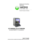
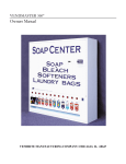
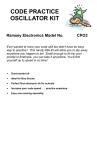
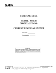
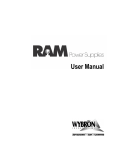
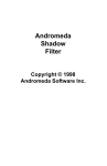
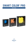
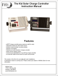
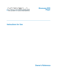
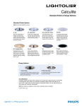
LT-150 Series
Table of Contents
Introduction
3
Safety Statements
3
Specifications
4
Setup & Operation
5
5
5
5
5
Unpacking
Optional Accessories
Installation
Operation
Maintenance
6
Lamp Replacement
Interchanging Reflectors
Cleaning
6
6
6
Troubleshooting
6
Diagrams
7
7
8
9
10
11
11
Isometric & Line Views
Exploded View
Part List
Schematic
Spectral Transmission Graph
Photometrics Chart
Limited Warranty
12
2
Introduction
Congratulations on your purchase of a Wildfire Long-Throw 150 UV-A Lighting Fixture, legendary performance
in an affordable compact size featuring lightweight, energy efficient electronic ballasting for flicker and noise free
operation and versatile interchangeable reflectors for a wide variety of configurations. Additional safety features
include automatic lamp failure shutdown, high temperature shutdown and hot re-strike protection. Please take a
moment to read this manual thoroughly before attempting to operate this fixture. Improper set-up, use or
servicing may cause damage to the fixture and/or lamp and void the unit’s warranty.
Safety Statements
CAUTION – RISK OF EXPOSURE TO ULTRAVIOLET (UV) RADIATION, DO NOT OPERATE WITHOUT
COMPLETE LAMP ENCLOSURE IN PLACE, OR IF FILTER GLASS LENS IS DAMAGED
DANGER – INTENSE HEAT. AVOID CONTACT BY PERSONS AND MATERIAL.
CAUTION – RISK OF ELECTRICAL SHOCK AND FIRE. DISCONNECT FIXTURE BEFORE RELAMPING.
USE WITH MAX 250W LAMP TYPE M58 (WILDFIRE IRONARC MODEL LMP-250D). DRY LOCATIONS
ONLY. NOT FOR RESIDENTIAL USE.
WARNING – THIS FIXTURE CONTAINS A HIGH INTENSITY UV METAL HALIDE LAMP, WHICH IS SAFELY
CONTAINED WITHIN AN INTERLOCKING HOUSING. WHEN THIS FIXTURE IS USED IN ACCORDANCE
WITH THE MANUFACTURERS OPERATING INSTRUCTIONS, NO HAZARDS EXIST TO MOST PEOPLE
STANDING WITHIN THE BEAM OF THE FIXTURE. HOWEVER, INDIVIDUALS SUFFERING FROM A RANGE
OF SUNLIGHT EXPOSURE DISORDERS, APHAKIC AND PSEUDOAPHIKIC, OR THOSE INDIVIDUALS
RECEIVING PHOTOSENSITIVE MEDICATION MAY RECEIVE DISCOMFORT IF EXPOSED TO
ULTRAVIOLET LIGHT.
HG – THE LAMP IN THIS FIXTURE CONTAINS MERCURY. MANAGE IN ACCORDANCE WITH DISPOSAL
LAWS. SEE: WWW.LAMPRECYCLE.ORG OR CALL 1-800-937-8065
3
Specifications
Ballast:
Electronic, Power Factor > 92%
Rating:
120-277VAC / 50-60Hz. / 2.5 Amps Max / 150W
Ballast Features:
Flicker & Noise Free
Automatic Lamp Failure Shutdown
Automatic High Temperature Shut Down
Automatic Hot Re-strike Prevention
Circuit Protection:
3 Amp Magnetic Over-current Breaker Switch
Lamp:
Wildfire IronArc™ 150 Watt Metal Halide Model LMP-150S (1000 Hr. Rated)
Beam:
LT-150F:
90°
LT-150WS:
50°
LT-150F:
20°
Reflector:
Spun Peened Aluminum, Alzak Coated
Lenses:
6” Round Tempered Borosilicate UV-A Filter Glass
6” Round Clear Boro Float Glass
Peak Spectral Transmission:
350-365nm
Optimum Operating Temperature:
+50°F to +120°F
Weight:
14.30Lbs. / 6.48kg.
Dimensions:
7.88” / 20.01cm High x 7.38” / 18.75cm Wide x 12” / 30.48cm Long
Accessory Bracket:
7.5” / 19.05cm
Standard Equipment:
Lamp (139-001)
Quick Trigger Pipe Clamp (147-020)
Safety Cable (147-002)
Optional Accessories:
7.5” Barn Door (146-001)
8” DMX Dowser (147-003)
8” DMX Iris (145-001)
Floor Stand (147-007)
Specifications subject to change without notice
Made in the USA
4
Setup & Operation
Unpacking
Unpack the fixture and carefully inspect for any signs of physical damage. Report any damage to Wildfire or
your local distributor immediately. Included with each unit should be the following items:
1. Pipe mounting clamp, designed to attach the fixture to a 11/2” to 2” pipe truss
2. Safety Cable, provided to secure the fixture when mounted on a pipe truss
3. Wildfire IronArc™ Lamp, Model LMP-150S
Before mounting the fixture you will need to install the lamp. Refer to Lamp Replacement on page 6 for correct
installation.
Optional Accessories
Floor Stand- This aluminum stand set enables you to mount your Long-Throw fixture on the floor for footlight
applications. Contact Wildfire or your local distributor for pricing.
Installation
After installing the lamp place the fixture in desired location. The fixture is equipped with a yoke assembly for
mounting. The yoke may be fitted with either a pipe clamp (included) for mounting on a pipe truss or a baby bail
block or junior pin for mounting on a light stand.
If the fixture is mounted on a pipe truss, be sure to use the included safety cable, looping it through the yoke
assembly and around the pipe truss. This will prevent the fixture from falling and causing possible injury in the
event that the pipe clamp was not securely tightened.
To adjust the angle of the fixture, loosen the knobs on either side of the unit slightly, rotate to desired angle and
tighten. Care should be taken to support the front of the fixture while loosening the knobs to prevent the fixture
from rotating forward and causing possible injury.
The fixture comes standard with a 7.5” Bracket assembly for attaching dowsers and scrollers such as Wybron’s
Eclipse or Coloram Series, as well as barndoors and other accessories. When using accessories with this
fixture, be sure to attach the safety cable provided by the accessory manufacturer to the fixtures yoke assembly.
Plug the fixture into the appropriate power source. If you are controlling the unit with a lighting control board, you
will need to make sure it is plugged into a non-dim circuit. If the fixture is plugged into a dimmable circuit, it will
not operate.
Operation
To strike the fixture push the power/breaker switch to the on position. After striking the lamp allow at least 2
minutes for the lamp to get to full brightness. Once the fixture has been powered up and the lamp has ignited if
you shut it off you will need to wait approximately 5 minutes to allow the lamp to cool before the fixture can restrike.
If the power/breaker switch is left in the on position during the cool down period, the hot re-strike prevention
circuitry in the ballast will prevent the lamp from striking until it is completely cooled. Once it has cooled
sufficiently, it will strike automatically. This fixture is also equipped with automatic lamp failure protection circuitry
that shuts the fixture down if the lamp should fail for any reason, preventing any damage to the fixture. In
addition there is high temperature protection circuitry that shuts the fixture down if the ballast case temperature
exceeds 85° C. When the fixture cools it will strike again automatically.
5
Maintenance & Troubleshooting
Lamp Replacement
Unplug the fixture. Remove any accessories from the front. Make sure the fixture is cool to the touch before
opening the front lens assembly cover. Unhook the clasps on either side of the fixture allowing the front lens
assembly cover to swing down. Although the LT-150 Series is designed to allow you to replace the lamp while
the reflector is still in place the procedure is easier when the reflector is removed enabling full access to the
socket (See Interchanging Reflectors below). Grasp the lamp in the center and pull forward to remove it from the
socket. If the lamp is difficult to remove rocking it gently from side to side will help loosen it from the socket.
Reverse this procedure to install the new lamp. Care should be taken not to touch the new lamp directly. Use a
cloth or glove when handling. If you have touched the lamp, it must be cleaned with alcohol to remove any oils
and fingerprints prior to striking. For maximum UV-A output, always use Wildfire IronArc™ lamps, and change
the lamp in your fixture every 1000 hours.
Interchanging Reflectors
There are three different interchangeable reflectors available for the LT-150 Series, a 20° Spot (125-005-02),
50° Wide Spot (125-006-02) and 90° Flood (125-007-02). These reflectors are designed to be removed and
replaced while the lamp is still in the fixture. To remove the reflector, unplug the fixture and remove any
accessories from the front. Make sure the fixture is cool to the touch before opening the front lens assembly
cover. Unhook the clasps on either side of the fixture allowing the front lens assembly cover to swing down.
Loosen the four set screws securing the reflector to the brackets on either side of the lamp housing and slide the
reflector forward out of the housing. Reverse this procedure to install the new reflector. The reflector attachment
brackets are stamped with S, WS and F indicating the proper set position for each reflector.
Cleaning
For best performance, the reflector, lamp and filter lens should be kept free of dirt and dust. At no time should
any cleaning chemicals or abrasives be used to clean any part of the fixture. Do not spray or apply any liquid
directly to any part of the fixture. Always unplug the unit before cleaning. For normal cleaning, a dry soft cloth
should be used to wipe any surface free from dust and light dirt. Cleaning the reflector will require that the lamp
be removed. Remove the lamp by following the instructions listed under lamp replacement above. Once the
lamp has been removed, gently wipe off the reflector using a soft dry cloth. In the event the reflector is heavily
soiled, lightly dampen the cloth with a mild window cleaning agent and wipe clean. The filter lens can be cleaned
in the same manner. The lamp should be cleaned with alcohol only.
Troubleshooting
The fixture will not strike: – Check to make sure there is power to the fixture. Make sure the power/breaker
switch on the back of the fixture has not been tripped. Unplug the unit. Check to see if it has a lamp installed
and that it is seated properly in the socket (See Lamp Replacement above). Check to see if the safety cutoff
switch is making contact by closing the lens cover and listening for a clicking sound. If the fixture still is not
striking, try replacing the lamp. If you have checked all of the above and the fixture still won’t strike, contact
Wildfire technical support at (310) 755-6780 or your local distributor.
The effect is not working anymore: – Try changing the lamp. The lamp in your Wildfire fixture is rated at 1000
hours. This does not necessarily mean that the lamp will “burn out” or not light after 1000 hours. It may continue
to burn for much longer period of time; however, the amount of UV it produces will be reduced considerably
causing the effect to appear as though it isn’t working. For maximum effect Wildfire recommends changing the
lamp every 1000 hours.
6
Diagrams
Isometric & Line Views
13.87"
16.87"
8.12"
7.37"
11.00"
7.00"
12.00"
7
Exploded View
45
6
7
44
8
9
3
36
46
32
35
50
14
1
33
48
31
5
37
49
11
10
28
23
47
29
12
14
21
30
14
24
27
17
12
34
52
20
22
54
53
15
25
14
13
18
12 26
4
2
51
39
17
19
40
41
16
42
8
38
43
19
Part List
#
QTY.
PART #
PART NAME
#
QTY.
PART #
PART NAME
1
1
102-009-01
Housing, Ballast, LT-150 Series
28
1
108-002
Socket, Lamp, G12 Base, 150W
2
1
102-010-01
Housing, Lamp, LT-150 Series
29
2
121-061
Washer, Tooth, #8, 18-8 SS
3
1
104-043-03
Control Plate, Rear, LT-250
30
2
121-069
Screw, M, PHL, PH, 8-32 x 3/4", 18-8 SS
4
12
121-016
31
1
110-011
5
1
105-001
Circuit Breaker, Carling, 3 Amp
32
3
121-059
Washer, Flat, #8, 18-8 SS
6
1
107-001
Cord, Power, 14 AWG, 9', 120V
33
4
121-020
Screw, M, TMB, 8-32 x 3/8" 18-8 SS
7
1
122-003
Strain Relief, Power Cord
34
2
104-006-01
Screw, TD, SM, PHL, PH, #10 x 1" 18-8 SS
Ballast, MH, Electronic, 120-277V/50-60Hz/150W
Bracket, Reflector Mount
8
1
122-002
Jam Nut, Black, 1/2"
35
1
125-005-02
Reflector, LT-150S
9
1
128-015-01
Label, Control, LT-150
36
1
125-006-02
Reflector, LT-150WS
10
1
104-049-01
Divider Plate, Lamp, LT-150
37
1
125-007-02
Reflector, LT-150F
11
4
121-068
Standoff, M-F, 8/32 x 5/16" x 3/8"
38
4
121-004
Screw, M, PHL,FH, 5-40 x 3/8"
12
10
121-037
Kepnut, 8-32, 18-8 SS
39
1
118-001
Hinge, Soss, #101, Chrome
13
1
104-048-01
Divider Plate, Ballast, LT-150
40
2
121-039
14
17
121-011
Screw, M, PHL, PH, 8-32 x 3/8", 18-8 SS
41
1
104-002-01
Bracket, Soss Hinge
15
1
104-016-01
Bracket, Switch Rod, Retaining
42
2
121-013
Screw, M, PHL, PH, 8-32 x 1/2" 18-8 SS
16
1
104-020-02
Rod, Switch, LT-250F & WS
43
1
103-001-09
Lens Door, 6" Round, LT-250
17
2
104-075-01
Bushing, Wire & Switch Routing
44
1
147-002
Cable, Safety, 1/8"
18
1
105-010
Switch, Safety Interlock
45
1
147-020
Clamp, Quick Trigger Slimline, Black
Knob, Yoke Adjustment, LT-Series
Screw, M, PHL, PH, 6-32 x 1/4" 18-8 SS
Nut, SP, 8-32 18-8 SS
19
10
121-005
46
2
120-001
20
1
104-078-01
Latch, Accessory Safety Catch
47
2
103-006-01
Spacer, Yoke Assembly
21
1
104-077-02
Base, Accessory Safety Catch
48
2
121-032
Rivet Nut, Blind, 16 x 3/8"
22
1
104-098
Spring, Double Torsion
49
2
121-060
Washer, Flat, 1.25" OD, 13/32 ID, .13 Thk, 18-8 SS
23
1
121-027
Bolt, Barrel, M, COM, PH, .25” x 1.5” 18-8SS
50
1
104-032-05
Yoke, LT-250 & LT-150
24
1
121-026
Screw, M, COM, PH, 10-32, .25” 18-8 SS
51
1
104-026-01
Screen, Safety, LT-250
25
2
118-002
Draw Latch
52
1
124-003
Lens, Clear Boro Float, 6" Round
26
2
118-003
53
4
104-080-01
Clip, Filter Restraining
27
1
139-001
54
1
123-003
Lens, UV, 6” Round
Catch, Secondary, Draw Latch
Lamp, MH, IronArc, SE, UV, 150W
9
Schematic, LT-150 Series
POWER SWITCH / CIRCUIT BREAKER
G
GREEN
N
WHITE
BLACK
L
RED
150W ELECTRONIC BALLAST
LAMP
150W
LAMP
GRND
WHITE
GREEN
BLUE
GROUND
120-277V
COM
SAFETY SWITCH
BLACK
10
GREEN
Spectral Transmission Graph
100%
90%
PERCENTAGE OF TRANSMISSION
80%
70%
60%
50%
40%
30%
20%
10%
UV-B
VISIBLE LIGHT
UV-A
WAVELENGTH /NM
Photometrics Chart
LT-150S Photometrics Chart
20° Spot
5/ 1
.52
10
/ 3.05
20
/ 6.10
30
/ 9.14
40
/ 12.1
9
50
/ 15.2
4
60
/ 18.2
9
70
/ 21.3
3
80
/ 24.3
8
90
/ 27.4
3
100
/ 30.4
8
11
0
/ 33.5
3
12
0/
36.
57
Distance in Feet / Meters
Beam Diameter Feet
1.80
3.50
7.10
Beam Diameter Meters
.55
1.07
2.16
3.23
4.30
5.36
6.46
7.53
8.59
9.66
443.0 110.7
27.6
13.3
6.9
4.4
3.0
2.2
1.7
1.3
Peak UV-A Intensity
W/cm 2
10.60 14.10 17.60 21.20 24.70 28.20 27.43 35.30 38.80 42.30
10.76 11.83 12.89
1.1
.92
LT-150WS Photometrics Chart
50° Wide Spot
5/ 1
.52
10
/ 3.05
20
/ 6.10
30
/ 9.14
40
/ 12.1
9
50
/ 15.2
4
60
/ 18.2
9
70
/ 21.3
3
80
/ 24.3
8
90
/ 27.4
3
100
/ 30.4
8
Distance in Feet / Meters
Beam Diameter Feet
4.70
9.30
18.70 28.00 37.30 46.60 56.00 65.30 74.60 83.90 93.30
Beam Diameter Meters
1.43
2.83
5.70
8.53
393.0 98.2
24.5
10.9
Peak UV-A Intensity
W/cm
2
11.37 14.20 17.07 19.90 22.74 25.57 28.44
6.1
3.9
2.7
2.0
LT-150F Photometrics Chart
90° Flood
5/ 1
.52
10
/ 3.05
20
/ 6.10
30
/ 9.14
40
/ 12.1
9
50
/ 15.2
4
60
/ 18.2
9
Distance in Feet / Meters
Beam Diameter Feet 20.00 40.00 60.00 80.00 100.00 120.00 140.00
Beam Diameter Meters
6.10
12.19 18.29 24.38 30.48 36.57 42.67
W/cm 2
308.0
77.0
Peak UV-A Intensity
19.2
8.5
4.8
11
3.0
2.1
1.5
1.2
.98
.77
1100
1200
980
1000
940
960
900
IR-A
920
880
860
820
840
800
780
760
740
720
700
680
660
640
620
600
580
560
540
520
480
500
460
440
400
420
380
360
340
320
300
280
0
IR-B
Limited Warranty
Wildfire, Inc. warrants to the original owner or retail customer, that for a period of three years
from the date of delivery of any Wildfire Fixture; whether used in a portable or permanent
installation, such fixtures will be free from defects in material and workmanship under normal
use and conditions.
Warranty does not cover any product or part of a product that has been subjected to accident,
negligence, alteration, abuse or misuse and excludes any accessories or parts not supplied by
Wildfire. Warranty does not cover expendable parts such as fuses, lamps, glass or any
components warranted directly to the owner by the original manufacturer. This warranty does
not extend to products not manufactured by Wildfire.
Wildfire’s responsibility under this warranty shall be to repair or replace at Wildfire’s discretion
such parts as determined to be defective upon Wildfire’s inspection. Wildfire will not assume
any responsibility for any labor expended or materials used to repair any equipment without
Wildfire’s prior written authorization.
Wildfire, Inc. shall not be responsible for any incidental, general or consequential damages to
property, damage for loss of use, time profits or income, or any other charges.
The owners’ obligation during the warranty period is to notify Wildfire of any suspected defect,
to obtain a return authorization number, and to return the product freight and insurance
prepaid to the following address:
Wildfire Service, 2908 Oregon Court Suite G1, Torrance, CA 90503
(800) 937-8065 (310) 755-6780
Collect shipments for freight allowances or shipments without return authorization numbers
will not be accepted.
THIS WARRANTY IS EXPRESSLY IN LIEU OF ANY AND ALL OTHER WARRANTIES
EXPRESSED OR IMPLIED INCLUDING THE WARRANTIES OF MERCHANTABILITY AND
FITNESS FOR A PARTICULAR PURPOSE AND ALL OTHER OBLIGATIONS AND
LIABILITIES ON WILDFIRE’S PART. THERE ARE NO WARRANTIES WHICH EXTEND
BEYOND THE DESCRIPTION ON THE FACE HEREOF. THE OWNER ACKNOWLEDGES
THAT NO OTHER REPRESENTATIONS WERE MADE TO HIM WITH RESPECT TO THE
QUALITY AND FUNCTION OF THE GOODS SOLD.
This written warranty is intended as a complete and exclusive statement of the terms thereof.
Prior dealings or trade usage shall not be relevant to modify, explain or vary this warranty.
Acceptance of, or acquiescing in, a course of performance under this warranty shall not
modify the meaning of their agreement even though either party has knowledge of the
performance and a chance to object.
This limited warranty gives you specific legal rights and you may also have other rights which
vary from state to state. If any action or preceding results from this warranty, the prevailing
party will be entitled to all costs and attorney fees incurred in defending or prosecuting such
actions.
2908 Oregon Ct. Suite G1, Torrance, CA 90503
310-755-6780 800-937-8065 Fax: 310-755-6781
www.wildfirefx.com
[email protected]
Wildfire and its symbol are registered trademarks of Wildfire, Inc. Torrance, CA
IronArc and its symbol are registered trademarks of Wildfire, Inc. Torrance, CA
Ignite Your Imagination is a registered trademark of Wildfire, Inc. Torrance, CA
c 2011 Wildfire, Inc.
215-004-03