1
Replace this file with prentcsmacro.sty for your meeting,
or with entcsmacro.sty for your meeting. Both can be
found at the ENTCS Macro Home Page.
Towards a unifying CSP approach for hierarchical
verification of asynchronous hardware
X. Wang
M. Kwiatkowska G. Theodoropoulos
Q. Zhang
1
School of Computer Science, University of Birmingham
Edgbaston, Birmingham B15 2TT, UK
Abstract
Formal verification is increasingly important in asynchronous circuit design, since the lack of a global synchronizing clock makes errors due to concurrency (e.g., deadlocks) virtually impossible to detect by means
of conventional methods such as simulation. This paper presents a hierarchical approach to asynchronous
systems verification using CSP and its model checker FDR. The approach reflects the hierarchical asynchronous hardware synthesis framework like Balsa and verifies the system at different levels of abstraction
against properties such as deadlock, delay insensitivity, conformance and refinement. We demonstrate the
feasibility of our approach by automatically detecting errors due to delay sensitivity and deadlock in simple
asynchronous hardware components.
Key words: Asynchronous hardware, Hierarchical verification, CSP, Model checking,
Levels of abstraction.
1 Introduction
The predominant synchronization technique in hardware design today is the utilisation of a global
clock whose transitions define the points in time when communication transactions between components can take place. This synchronous approach, however, has reached a critical point [21].
Increased clock speeds make on-chip clock skew significant and inter-chip skew a major problem. As VLSI technology advances and systems become larger, faster and more complex, timing
problems become increasingly severe and account for more and more of the design and debugging expense. Thus, the last decade has witnessed an explosion of interest in asynchronous design
techniques, which do not rely on global clocks but achieve synchronization by means of localized
handshake synchronization protocols between the communicating subsystems.
Several asynchronous design techniques have been developed [21,17,11] and are progressively
finding their place in the mainstream VLSI design. The liberation from global synchronisation,
however, does not come without a price. The elimination of the clock results in highly concurrent,
non-deterministic systems 2 , which are more difficult to specify, understand, design, evaluate and
1
{X.Wang,M.Z.Kwiatkowska,G.K.Theodoropoulos,Q.Zhang}@cs.bham.ac.uk
Note that highly concurrent, non-deterministic systems can have sequential and deterministic blackbox behaviours
and that the definitions of determinism in asynchronous systems and in synchronous systems are different.
2
c
2004
Published by Elsevier Science B. V.
Wang
verify. The variable delays and the non-deterministic behaviour (i.e., in the sense of asynchronous
systems) of arbiters introduces new problems that render simulation alone inadequate as testing
methodology. For instance, a distinguishing feature of asynchronous hardware is that they are
susceptible to deadlocks, an issue which does not exist in systems synchronised by a global clock
and operating in lock step. The correctness of the asynchronous system should not depend on the
ordering of independent streams of events; a correct design should be deadlock free for all possible
combinations of events, which can only be guaranteed by formal verification, not simulation.
Though many CAD environments exist for conventional, sequential, synchronous hardware
description languages, they are proving inappropriate for asynchronous hardware as they are fundamentally unsuitable for describing concurrent nondeterministic asynchronous behaviour. While
appropriate front-ends or translators exist for synchronous designs which allow users to work directly with VHDL or Verilog, with the tools building an (appropriately reduced) model and performing checks, formal verification of asynchronous hardware is not as well established as that for
synchronous hardware.
In this paper we propose a formal verification approach for asynchronous hardware systems
using Balsa, the CSP-based specification and synthesis system developed by the AMULET group
at the University of Manchester [6,7]. Balsa is endowed with simulation, but not verification, tools.
We demonstrate how Balsa programs, handshake networks and asynchronous gate circuits can be
translated into CSP, which in turn enables the use of FDR [9], the mature model checker for CSP, to
serve as the back-end verification tool. Data independence can be employed to tackle the datapath
reduction problem. The proposed approach can be implemented as an add-on to existing Balsa
design and synthesis process.
The paper is structured as follows. We first outline the VLSI compilation framework for asynchronous hardware design. Then we propose a hierarchical verification approach, as an extension
of the framework, based on the use of CSP as the unifying formalism. Next, we illustrate the
approach with the help of a Balsa program fragments, handshake networks, asynchronous logic
circuits and its synthesis process. For each level (three in all), we give a translational semantics of
the Balsa components in CSP and describe the outcome of verification experiments. Finally, we
conclude the paper by discussing related work and future plans.
2
High-level asynchronous circuit compilation
Languages for modelling asynchronous systems (especially at the high level) are frequently based
on CSP (Hoare’s Communicating Sequential Processes), whose channel communication paradigm
has been extensively advocated as particularly suitable for describing the behaviour of asynchronous
hardware systems. Of the various CSP-based approaches that have been used (e.g., [22,16,12,10]),
a particularly promising one employs silicon compilation to automatically generate gate-level implementations from high-level specifications; most notable examples include Brunvand’s [4] work,
Tangram [2] and Balsa [6,7].
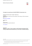
Within this asynchronous logic synthesis framework (Figure 1), a CSP-based parallel programming language is usually employed to give a high-level algorithmic description of the design.
From such a description, syntax-directed compilation creates a network (composition) of handshake components, where each language construct in the program is mapped to a corresponding
handshake implementation. Handshake components are usually pre-designed and stored in a library in the form of gate-level circuit fragments.
2
Wang
Figure 1.
3
The three-level VLSI compilation framework
A hierarchical approach to asynchronous hardware verification
In this paper, based on the silicon compilation framework, we propose a hierarchical approach to
verifying asynchronous hardware designs, which utilises FDR, the model checker for CSP. The
approach centres around the two hierarchies in silicon compilation: the hierarchy of abstraction
levels (as shown in Figure 1) and the hierarchy of component composition.
The key observation is that CSP is appropriate for describing all three levels of system description. The top level describes a synchronous system like in standard CSP; it utilizes fine-grained
parallel (parallel operator within sequential composition) that is rarely supported by other model
checkers. The lower two levels describe asynchronous systems, which poses challenges to the expressive power of standard CSP. Based on our novel idea of a scheduler, we find that asynchronous
systems can not only be modelled in CSP in a direct and intuitive way, but also be simplified to use
just the traces model. In some sense, our work is similar to Dill’s trace theory of asynchronous circuits [5]. At all three levels, the systems will be highly concurrent; past experiences have indicated
that FDR works well with a high degree parallelism [20].
Another advantage of using CSP and FDR, we find, is that refinement is natural and particularly effective in reducing a verification problem across component composition hierarchy. For
a component, it can be described from two points of view: an implementor’s view and a user’s
view. The user’s view treats the component as a blackbox and provides an abstract behavioural
specification. It is usually much simpler than its implementation counterpart, which may involve
complicated interactions among sub-components. If we have verified the refinement of the implementation by the specification, the specification can replace the implementation in any further
verification work. Similarly, using the idea of protocols, we are able to hierarchically reduce the
verification of asynchronous systems as well.
3.1
Hierarchy across abstraction levels
Abstraction hierarchy is an important tool for managing the complexity in asynchronous circuit design, both for human designers as well as for verification tools. At the programming language level,
we use abstract concepts such as synchronous broadcast communication, shared variables, sequential and parallel composition, etc, to describe a high-level algorithmic view and structural design of
the hardware system. At the handshake level, two-way asynchronous handshake signals, which exploit a basic set of handshake components (Fork, Split, Variable, Loop, Concur, BinaryFunc, etc.),
implement synchronous broadcast communication, interleaved variable accesses, control sequentiality and parallelism, etc. At the basic gate level, handshake signals are mapped to transitions on
the wires. The function of basic handshake components is synthesized from basic logic gates.
3
Wang
Figure 2.
The hierarchy of abstraction
Given a large asynchronous hardware design, it is often infeasible to verify the whole design
at the lowest level. By utilising the abstraction hierarchy, the overall verification problem can
be decomposed into smaller, more tractable problems at different levels. Since we employ CSP
at all levels of abstraction, it is possible for us to establish a formal semantic link between the
levels, based on various techniques such as behaviour Refinement, Action refinement, abstract
Interpretation (RAI), etc. (In section 6.3, an example will be given on how to handshake expand
(i.e. RAI-refine) a Balsa program in CSP into several different handshake protocols in CSP.) In
a systematic approach, we expect to utilize this link in the future to validate Balsa’s compilation
functions and synthesis algorithms and prove some kind of correctness-by-construction results for
the system.
3.2 Hierarchy across component grain-sizes
Within an abstraction level, small components are often combined to form more complex components. Flattening the composition hierarchy to perform verification is undesirable. Here we will
adopt specification-based refinement checking and protocol-based closed-circuit testing to verify
asynchronous hardware system. The former applies to the synchronous blocking communication
of the Balsa language level, and the latter to the asynchronous non-blocking communication of
handshake and basic gate levels.
In the synchronous case, although events are blocking, delay is generally irrelevant. At this
level we apply the traditional CSP refinement, that is, separate specification of a component from
its implementation; after checking, the specification can be used instead of implementation when
composing components.
An asynchronous hardware system, at lower levels, is an input/output system which consists
of a collection of asynchronous components connected by channels. A channel is two-way and
associated with delay. Components communicate by sending/receiving signals with non-blocking
semantics. Although CSP enforces synchronisation of input and output on the same channel into
a single event, we choose to model the two operations separately and use a scheduler to explicitly
schedule the delay and synchronization of input and output. A scheduler will first nondeterministically select an enabled output (those in the initials of the process) of a sending component and then
force it onto the input of the receiving component. This nondeterminism of the scheduler can simulate all the possible delay scenarios of the system. If a system runs correctly with a scheduler, this
implies that the system runs correctly in all delay scenarios. That is, the system is delay insensitive.
If there is an assumption on channel delay, such as isochronic fork, the scheduler can be modified
to reflect the assumption. This enables us to verify quasi-delay insensitive and speed-independent
systems.
4
Wang
An asynchronous input/output system can be an open-circuit system or a closed-circuit system.
A closed-circuit system models a complete system, which neither inputs from nor outputs to the
environment. An open-circuit system models a component. Generally speaking, an open-circuit
system can be described by a protocol, which dictates all its legal sequences of input and output
events with environment. The use of the protocol can be two-fold: for a system, the protocol
describes its environment assumption, and, for a component in a larger system, its behavioural
specification.
When verifying a closed-circuit system, we run the system in parallel with the scheduler. If it
deadlocks when the scheduler forces the output onto the input, we say the system is incorrect, in
the sense that the system does not constitute a good environment in which all the protocols of the
sub-components are obeyed. Because the scheduler participates in the occurrence of every event,
any deadlock of the scheduler will be global, and hence easy to check in FDR.
When verifying an open-circuit system, we use its protocol as the environment of the system to
close-circuit it and verify as before using the scheduler. Then deadlock freedom implies not only
that the system is a correct environment for all its sub-components, but also that the system correctly implements, or conforms to, the protocol. A complete example of open-circuit verification
will be shown in section 7.
4 Balsa
Balsa is both an asynchronous hardware synthesis framework and the CSP-like language for describing such systems. Balsa generates purely asynchronous macromodular circuits similar to
those of Philips’ Tangram [2]. (One major difference is that Balsa extends Tangram with handshake
enclosure [6,7].) Balsa is technology independent (e.g. channel connections can be implemented
using speed-independent or delay-insensitive schemes) and it targets standard cell and FPGA technologies for producing gate-level netlists. Three levels of simulation are supported: behavioural
at the Balsa level, and functional and timing (using native simulators of the supported commercial
CAD tools) at the basic gate and layout levels (Figure 3). No verification tool is available.
Fainter lines in Figure 3 denote manual processes. It is obvious from the figure that most
validation work in Balsa is done manually.
Figure 3.
Balsa System
5
Wang
5
Asynchronous hardware programming
Hardware programming enables system designers to approach the design of complex asynchronous
VLSI circuits at a high level of abstraction.
5.1
A translational semantics of Balsa in CSP
Balsa supports most of the features of the CSP concurrent language, such as blocking synchronous
communication (input/output), assignment, (input-)guarded command, sequential composition,
parallel composition, iteration and conditional. A Balsa-described component will synchronously
communicate with the environment by outputting/inputting data to/from channels. A channel can
connect two or more components; output on the channel will be broadcast to the components receiving data from the channel. Generally speaking, simultaneous output to the same channel can
cause interference.
Balsa does not have a formal semantics, though Tangram has one based on handshake processes [2]. But handshake processes are asynchronous and the semantics is essentially at the handshake level. It is much less abstract than at the top level. In this paper we give a CSP translational
semantics to Balsa programs directly at the top level. The variant of CSP language we use is similar to the ones in [16] and [8], which have an imperative flavour but can give terse descriptions of
asynchronous circuits 3 :
Syntax of CSP
CMD
::= c?x : b | c!e | Skip | CMD 2 CMD0 | CMD u CMD0
| CMD o9 CMD0 | CMD |[ chans ]| CMD0 | CMD k CMD0 | CMD \ chans
| l(e1 , ... , en ) | if b then CMD else CMD0 | {l(z1 , ... , zn ) = CMD, ...}
where x, y and z are variables 4 , chans is a set of channel names (e.g., {c1 , ... , cn }), b is a boolean
expression and e is a value expression. c?x : b is a selective input command; input x on c is
accepted iff it satisfies b. |[ chans ]| is an interface parallel operator; it synchronize its two subprocesses only on the events in chans. k is a special alphabetized parallel; it synchronizes its
two sub-processes only on the events shared by their minimal alphabets (i.e., the set of events
syntactically occured in their process expressions). Sequential composition binds stronger than
choices, while choices are stronger than parallel composition.
As a running example, we will use the Balsa code fragment for an arbiter:
import[type]
-- importing some types and library procedures
procedure Arb
-- procedure defines a component
(input NTarget1, NTarget2:InsAdd; -- input of the component
output NTarget : InsAdd)
-- output of the component
is local variable C: bit
-- internal variable
begin
loop arbitrate
-- arbitrate is two-way choice
NTarget1 then
-- first one waits on NTarget1
if NTarget1.c = C
then NTarget <- NTarget1 end
3
The conversion to CSPm of FDR is trivial, as can be found in our CSPm scripts [27] of the examples in the paper.
In the rest of paper, all the variables are assumed to have been declared in the beginning of specifications so that we
can omit them for brevity.
4
6
Wang
| NTarget2 then
C := NTarget2.c
|| NTarget <- NTarget2
end
-- second one waits on NTarget2
-- input from NTarget2 outputted to NTarget
end
end
The arbiter Balsa program can be translated to CSP process arb in a straightforwardly way
shown below:
channel ntarget, ntarget1, ntarget2 : ADDR.COLOR
channel nt1 end, nt2 end
channel read, write : COLOR
arbc = ntarget1?x?c o9 read?c0 o9 if c = c0 then ntarget!x!c else Skip o9 nt1 end o9 arbc
2 ntarget2?x?c o9 (write!c k ntarget!x!c) o9 nt2 end o9 arbc
lcv(c) = read!c o9 lcv(c) 2 write?c0 o9 lcv(c0 )
arb = (arbc k lcv(0)) \ {read, write}
Balsa supports several features not present in CSP. Firstly, it has variables and assignment;
that is, Balsa programs are imperative. There are two possible ways to translate it into declarative
CSP: one is to translate a variable as a process and read/write operations as communications on its
channels [19], and the other is to translate processes as state passing functions [24]. We will use the
former in this paper, which is shown to be an efficient technique in respect of FDR [20]. Thus, the
local variable C in the Balsa program is translated as the process lcv. Note that, when two processes
are sharing the same variable, accesses to the variable are interleaved. So channel communication
on variable processes is narrowcast, rather than broadcast as in other Balsa channels.
Another special feature of Balsa is guard enclosure (i.e., extended rendezvous), which is mostly
associated with the Select and Arbitrate commands. Semantically, it involves a long lasting event
enclosing a collection of shorter events. In CSP, we model it by a pair of events (we call it a
duration pair), one representing the start of the ‘duration’, and the other the end. For example,
the input and output events on channel ntarget1 are guard enclosures and are modelled by duration
pairs (ntarget1?x?c, nt1 end) and (ntarget1!x!c, nt1 end).
Duration pairs are also useful in detecting simultaneous occurrences of events, which, due to
its interleaving semantics, is not captured by CSP. Detecting simultaneous occurrences of events
will be very useful, as it can imply interference on channel/variable accesses or interference on
choice activations. Interference on choice activations (i.e., simultaneous activation of two or more
branches of a choice) distinguishes an Arbitrate command from a Select command; that is, only
Arbitrate can be used when there is interference 5 .
5.2
Verification of Balsa programs in CSP
CSP has a mature verification tool, FDR, and a data reduction theory, data independence. To
utilise them in verifying Balsa-described asynchronous hardware systems, we need to implement
our hierarchical verification approach in FDR.
For a Balsa implemented system I, where I needs to satisfy the specification S, we can translate
I and S into CSP and obtain SYS and SPEC. If SYS and SPEC involve large data types, data
5
Note that, at the Balsa level, we will not distinguish Select from Arbitrate semantically, although this distinction has
to be made at lower levels.
7
Wang
independence reduction can be applied yielding the reduced sys and spec. We can then check the
refinement of sys by spec in FDR, which establishes that I indeed conforms to the specification S.
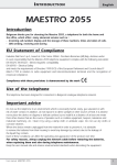
As an example, Figure 4 illustrates an asynchronous circuit which has been taken from SAMIPS,
an asynchronous implementation of the MIPS processor currently under development at the University of Birmingham [25]. The figure shows an abstraction of the first two pipeline stages of
SAMIPS, namely Instruction Fetch (IF) and Instruction Decode (ID).
IF is essentially the instruction prefetching unit of the processor, where the physical address
- either the current program counter (PC) incremented by four (ADD4) or a new target address
from datapath, if a control hazard occurs - is calculated and then sent to PC and the main memory,
through an arbitration unit (AAU). A new target address (NTarget2) will typically be the result
of a control hazard that takes place in the datapath. To stop prefetching invalid instructions (via
NTarget1) (and discard those that have been prefetched) in SAMIPS, a colouring mechanism has
been developed [23], whereby both the state of the processor at any particular moment and the
instructions are “coloured”. Instructions are executed only if their colour matches that of the
processor, which changes every time a control hazard occurs and is piggybacked on the new target
address to colour the new instruction stream. To break the current prefetching loop, the arbitration
unit AAU keeps a copy of the colour as the new target addresses pass through it. To simplify
our example, we assume only two colours (0 and 1), and one type of control hazard, namely the
execution of a jump instruction in the ID stage.
IF
ID
PCvalue
+4
ADD4
PC
BaseAddr
DeCode
NTarget
AAU
NTarget1
Figure 4.
NTarget2
The instruction fetching circuit
The CSP equivalent of the arbiter unit (AAU) has been shown above. The PC unit is just a
buffer storing the program counter:
pc(x, c) = pcvalue!x!c o9 ntarget?x0 ?c0 o9 pc(x0 , c0 )
The ADD4 unit is an abstraction of several units of a processor. It accepts an address from PC.
Then, on one hand, it fetches the instruction at that address and sends to the DECODE unit. On the
other hand, it adds four to the address and sends it to AAU. The instruction set here is simplified to
distinguish only jump ones from non jump ones. We use nondeterministic choice ‘u y : INS •’ to
abstract the instruction fetching from the memory:
datatype INS = jump | non jump
channel baseaddr : ADDR.COLOR.INS
add4 = pcvalue?x?c o9 ( ntarget1!(x + 4)!c o9 nt1 end k u y : INS • baseaddr!x!c!y ) o9 add4
8
Wang
The DECODE unit accepts input from ADD4. If the instruction is a jump and the colour is
correct, it changes the current colour and sends it with the jump destination to AAU. The jump destination is nondeterministically selected ‘u x0 : ADDR •’; this is an abstraction. If the instruction
is not a jump and the colour is correct, the instruction will be sent to later stages of the pipeline for
execution. Because we abstracted the later stages of the pipeline in this example, the instruction
will be treated similarly to the instruction with an incorrect colour: the script simply returns by
calling decode(c).
decode(c) = baseaddr?x?c0 ?yo9
if c = c0 ∧ y = jump
then u x0 : ADDR • ntarget2!x0 !(1 − c) o9 nt2 end o9 decode(1 − c)
else decode(c)
- - - discard or execute ‘y’
This completes the CSP translation of the system. However, the system does not have a specification. It is a closed system, since we have chosen to abstract away the remaining parts of the
pipeline. Therefore, we only need to check deadlock freedom of the system below:
system = decode(0) k add4 k arb k pc(0, 0)
In system, ADDR can be a very large data type and may blow up the state space dramatically for
FDR. By applying data independence theory, ADDR is shown to be weakly data independent [15].
According to theorem 5.1.2 in [15], it can be reduced to a data type of size 1. Using the reduced
model with only three addresses in ADDR (for illustration purposes), we have found the deadlock
trace for the instruction fetching system with a buffer-less arbiter.
pcvalue.0.0, baseaddr.0.0.jump, ntarget1.4.0, ntarget.4.0, nt1 end, pcvalue.4.0,
ntarget1.8.0, ntarget.8.0, nt1 end, ntarget2.8.1
It deadlocks because DECODE is trying to send colour 1 and address 8 to PC via the arbiter.
But PC is waiting to send the program counter 8 and colour 0 to ADD4, which in turn is waiting
to send address 8, colour 0 and some instruction to DECODE. This forms a loop of waiting
indefinitely.
We can correct the system by adding a buffer to the arbiter, thus breaking the loop. Using FDR
we have shown that the corrected system is deadlock-free 6 .
6
Handshake networks
After a system has been programmed in Balsa, the Balsa compiler will automatically translate
the program into a network of handshake components and we enter the world of asynchronous
nonblocking communication.
6.1
Handshake components
A handshake component connects with the environment via a number of handshake channels.
Whereas Balsa channels are synchronous, the handshake channels have different characteristics.
Firstly, at the Balsa level, each communication constitutes one synchronous blocking event; at
6
Detailed Balsa and CSPm scripts can be found at [27].
9
Wang
the handshake level, however, each communication consists of a pair of non-blocking events, req
and ack. This is called handshake expansion; it implements the transition from synchrony to
asynchrony. Depending on which side initiates the communication (i.e., by sending req), the ports
on a channel are divided into active ports and passive ports. Naturally, one channel connects just
one active port with one passive port.
Secondly, a handshake channel connects only two adjacent components. It can either synchronize them (i.e., representing the control path of the circuit) or communicate data between them (i.e.,
representing the datapath of the circuit). For datapath, it collects information from one and distributes to the other. On one channel, a component cannot send in a communication while receiving
in another 7 . To connect multiple components, as Balsa channels do, some special handshake components are needed to do the plumbering (e.g., forking and merging) to create multi-way passages.
In order to implement the broadcast and narrowcast communication in Balsa, the plumbering also
needs to perform information copying and information flow arbitration/selection for the correct
collection and distribution.
Thirdly, depending on whether there will be interference on choice activations or channel/variable
accesses, we will be able to simplify the merging implementation by replacing arbitration with selection.
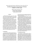
For example, the component in the left part of Figure 5 is a FalseVariable (FV) handshake
component.
S
WD
WDr
RDr
RD
WDa
Figure 5.
Sr
Sa
RDa
The false variable and its protocol in STG
The FV handshake component resembles a normal Variable, with one passive (denoted by an
open circle) write port WD and one passive read port RD 8 . It differs, however, in the presence of
an active (denoted by a filled circle) probe port S. The component is named FalseVariable because
it does not store data.
The behaviour of the FV component (the Signal Transition Graph [14] in Figure 5) can be
described as follows. A WRITER process produces data that is pushed on channel WD. A READER
process consumes data by pulling it on channels RD. The READER must wait until valid data has
been sent by the WRITER before reading. Channel S is used by FV to indicate the arrival of
valid data on channel WD. Since FV does not store data, the WRITER is allowed to take the data
away only after the READER has consumed it. All channels are implemented using request and
acknowledge signals. The FV component is usually used to implement arbitrate/select commands
in Balsa.
7
But biput ports [2] are allowed. Biput ports exchange information (both send and receive data) in every communication.
8
This is a simplification; usually we will have multiple read ports.
10
Wang
6.2
Syntax-directed compilation and handshake component network
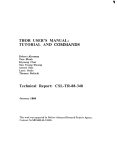
By compiling the arbiter program written in Balsa 9 , we can obtain the handshake component
network in Figure 6. The edges with arrows represent datapath while the edges without arrows
represent control path.
The central component named clr is the local colour variable of the arbiter program. On its
left, components ‘DW’ and ‘(>’ implement the arbitrate itself. Below it, we see the sub-network
implementing the first branch of arbitrate, and above it, the sub-network for the second branch.
FV components are used to accept data input from channel Ntraget1 and Ntarget2. ‘|’ component
is used to multiplex data flow from the two branch and output to Ntarget channel.
NTarget2
s
activate
#
->
FV
[32
:32]
DW
->
||
|
clr
(>
NTarget
[32
:32]
=
->
@1
s
FV
->
NTarget1
Figure 6.
6.3
The handshake network for Arbiter
Verification of handshake networks in CSP
Let us assume that a Balsa program B, whose semantics in CSP is C, is compiled into a handshake
network N. m is a handshake component in N, whose protocol in CSP is c. In order to verify that
N correctly implements B, we need to first handshake-expand (RAI refine) C in order to get the
handshake level protocol PRT for the network.
Then, for each m in N, its protocol c is used as its behaviour specification. Composing up these
cs (as they are connected in N) gives us a CSP translation of the network, SYS.
Putting SYS and PRT in parallel with a scheduler, we can check for deadlock in FDR to prove
that SYS conforms to PRT, that is, N is a correct implementation of B.
In the instruction fetching example above, the CSP description of the arbiter unit arb is equivalent to:
spec(c) = ntarget1?x?c0 o9 if c = c0 then ntarget!x!c else Skip o9 nt1 end o9 spec(c)
2 ntarget2?x?c0 o9 ntarget!x!c0 o9 nt2 end o9 spec(c0 )
Since NTarget1 and NTarget2 are both passive ports, while NTarget is an active port, the protocol above can be handshake-expanded into:
9
Note that although the distinction between Select and Arbitrate is not reflected in Balsa CSP semantics, it is utilised
in the compilation process to optimise the resulting network.
11
Wang
prot0 (c) = NT1.r?x?c0 o9 if c = c0 then NT.r!x!c o9 NT.a else Skip o9 NT1.a o9 prot0 (c)
2 NT2.r?x?c0 o9 NT.r!x!c0 o9 NT.a o9 NT2.a o9 prot0 (c0 )
Or, with more concurrency, into:
NT1.r?x?c0 o9 if c = c0 then NT.r!x!c o9 NT.a else Skip o9 NT1.a o9 prot(c)
k NT2.r?x?c0 o9 NT.r!x!c0 o9 NT.a o9 NT2.a o9 prot(c0 ) k serialize
serialize = NT.r?x?c0 o9 (NT1.a 2 NT2.a) o9 serialize
prot(c) =
prot is the protocol for (arbitrate) handshake network of Figure 6, while prot0 is for optimised
(select) handshake network when there is no interference on choice activation.
Due to space limitations, we will not show the verification at the handshake level. Instead, a
full example using protocol-based closed-circuit testing will be shown at the gate level.
7
Basic gate circuits
After the basic set of handshake components (40 plus for Balsa) is identified and defined, each
component can be synthesized into a gate level circuit, manually or automatically, based on some
encoding scheme. An encoding scheme decides how to implement abstract req/ack and data signal
of the handshake level using voltage transitions of wires in gate-level circuit.
7.1
Asynchronous logic synthesis
(a)
Figure 7.
(b)
The gate-level protocol of FV and T elements*
Given a handshake component, the initial input to the synthesis process should be its handshake protocol. The synthesis process then concretizes (RAI refines) the protocol according to the
encoding scheme, yielding a new gate-level protocol. This is a design process; the new protocol must consider the implications it has on the speed, cost, safeness, etc, of synthesized circuits.
General principles of gate-level protocol design include allowing more concurrency, maintaining
delay-insensitive interface behaviour, avoiding state dependency that is too costly to implement,
etc.
For example, the FV component has recently been re-designed by Manchester AMULET group
for a dual-rail level-signalling scheme. The new refined protocol is shown in Figure 7(a).
12
Wang
Because of level-signalling, useful transitions will be usually upward (+). The downward
transitions (−) are needed just to return the voltage to zero in order to prepare the next round of
upward transitions.
Based on the new protocol, their proposed implementation is shown in Figure 8. The behaviour
of the T element is specified by the protocol of Figure 7(b) 10 .
One point to note in the circuit is that dual-rail scheme encodes control signals WDr and RDa
into data flow. Data is transmitted on a bus of n-bit width. Due to delay variation of wires, there is
a delay between the arrival of the first bit and the arrival of all bits. Duration pairs can model this
well. In Figure 7(a), WDr0+ denotes the arrival of the first bit on incoming bus, while WDr[1,n−1]+
denotes the arrival of all bits. The detection of the arrival of all bits is implemented by the CD
element (Completion Detection) in Figure 8. The ReadPort element connects the incoming bus
with outgoing bus. The opening and closing of the port is controlled by RDr.
Figure 8.
The implementation of false variable*
The detailed reasoning behind the derivation of the gate-level protocol from the handshake
protocol can be found in [18] at [27]. It is also obvious there that they are very much concerned
about the delay insensitivity of the above design, and they can only use complicated informal
reasoning to try to exclude delay-sensitivity.
7.2
CSP verification
Imagine that a handshake component H is implemented in a gate-level circuit T. T’s protocol is
captured by PRT in CSP. g is a gate-level element in T, and its protocol in CSP is c. Then, for each
g in T, its protocol c is used as the behaviour specification. Composing up these cs (as they are
connected in T) yields a CSP translation of the network, SYS.
Putting SYS and PRT in parallel with a scheduler, we prove that SYS conforms to PRT by
checking for deadlock in FDR. Sometimes an element g may itself be implemented by even more
basic elements in circuit t (e.g., the T elements in the FV circuit). Then the protocol of g will be
the protocol of t. By translating t into CSP, we can similarly prove t implements g.
For the FV example, after abstracting the data bus and completion detection, the gate-level
circuit implementation becomes:
10
The input/output wiring definition can be found in Figure 9.
* Figure 7 and 8 are taken from [18].
13
Wang
WDr0
Ir
T
Ia
Or
Sr
Oa
Sa
Iand1
Oand
WDa
Oc
ANDn
Ic1
C
IandN2
O1’
O2’
Ic2
fork’
I’
RDr
In1
WDr
Figure 9.
I
fork
READ PORT Out
In2
O1
O2
RDa
The abstract implementation circuit
Translating the STG in Figure 7(a), we obtain the CSP protocol for the circuit as:
protocolFV = (writer k reader) o9 WDa.down o9 protocolFV
writer = (WDr.up k RDr.down) o9 WDa.up o9 WDr.down
reader = (WDr0.up o9 Sr.up o9 RDr.up k WDr.up) o9 RDa.up o9 Sa.up o9 Sr.down o9 RDr.down
oRDa.down o Sa.down
9
9
Similarly, we can get the behaviour specification of the T element as:
protocolT = Ir.up o9 Or.up o9 Oa.up o9 (Or.down o9 Oa.down k Ia.up o9 Ir.down) o9 Ia.down o9 protocolT
There are two forks in the circuit; their behaviour specification is:
fork0 = I.up o9 (O1.up k O2.up) o9 fork1
fork1 = I.down o9 (O1.down k O2.down) o9 fork0
The Muller-C element has the behaviour:
protocolC = (Ic1.up k Ic2.up) o9 O.up o9 protocolC0
protocolC0 = (Ic1.down k Ic2.down) o9 O.down o9 protocolC
The READPORT element, after abstraction of data bus, functions like an AND gate:
readport = (In1.up k In2.up) o9 Out.up o9 readport0
readport0 = ( In1.down o9 (Out.down k In2.down) 2 In2.down o9 (Out.down k In1.down) ) o9 readport
The behaviour of the one-input negated AND gate could be similarly specified. But because
it is used in this particular circuit in a limited way, its protocol is rather different from the above.
This is a good example of verification using protocols instead of the full specification of elements.
andN = IandN2.up o9 (Iand1.up k IandN2.down) o9 Oand.up o9 andN 0
andN 0 = Iand1.down o9 Oand.down o9 andN
One important observation we can make of the above specification is that no element shares
any event. It is due to our principle of separating input from output so that we can use the scheduler
to link and synchronize them. The definition of the scheduler is as below:
signalling(x, y) = x?z o9 y!z
scheduler = ( signalling(WDr0, Ir) 2 signalling(Oc, WDa) 2 signalling(WDr, I)
2 signalling(O1, Ic2) 2 signalling(O2, In2) 2 signalling(O10 , IandN2)
2 signalling(O20 , In1) 2 signalling(Oand, Ic1) 2 signalling(Ia, Iand1)
2 signalling(Or, Sr) 2 signalling(Sa, Ia) 2 signalling(RDr, I 0 ) 2 signalling(Out, RDa) )
o scheduler
9
14
Wang
signalling(x, y) connects the output channel x of one element to the input channel y of another
element. Whenever an output 11 is made on x, the scheduler will force it onto y.
Putting all the elements in parallel with the scheduler and the protocol protocolFV, we finally
obtain our testing system below.
test system = scheduler || protocolFV || protocolC || fork0 || readport || fork00 || andN0 || protocolP
Checking the test system with FDR, we find it deadlocks. One of the deadlock traces is:
(WDr.up, I.up) (O2.up, In2.up) (WDr0.up, Ir.up) (Or.up, Sr.up) (RDr.up, I 0 .up) (O20 .up, In1.up)
(Out.up, RDa.up) (Sa.up, Oa.up) Ia.up
The system deadlocks on ANDn in this trace because Ia.up from T overtakes the arrival of
RDr.up via fork0 . This is illegal according to the ANDn protocol, because, otherwise, ANDn will
output Oand.up and through the Muller C element will cause WDa.up. This is clearly not allowed
by the FV protocol; it means that the writer can remove the data before the reader gets it.
However, by adding an isochronic fork constraint to fork0 , the arrival of RDr.up on ANDn
will overtake Ia.up, and so block the Oand.up in advance. This is verified by FDR. Actually,
with another minor constraint on timing, we prove with FDR that the above implementation is
correct 12 .
Our scheduler approach can check asynchronous circuits not only for safety conditions as in
trace thoery [5] but also for progress conditions [8]. The merit of introducing a scheduler explicitly is that it enables us to use standard CSP theory, rather than specialised asynchronous theories [5,13]. It makes ‘asynchrony’ much easier to understand and verify. The formal semantic link
and rigorous comparison with the asynchronous theories, however, need await our recent development of a thoery for scheduler.
8
Related work and comparison
Formal verification of asynchronous hardware is not as well established as that for synchronous
hardware, and is known to suffer from the state explosion problem. For example, the verification
of the Amulet processor using CCS and the Concurrency Workbench was hindered by state space
explosion [3]. It was circumvented by verifying only parts of the system, discarding the datapath
description and simplifying the processor model by treating only one class of instructions at a time.
For our approach, we propose to divide the verification work across both the abstraction hierarchy and the component hierarchy so that we will not need to verify the expanded system at the
lowest level of abstraction. Our approach to verification should be viewed as an add-on to Balsa
design and synthesis process. Balsa automatically gives the division of ‘labour’ across abstraction
levels, and enables us to solve different verification problems at different levels. It is also based
on handshake component reuse and compositional construction of asynchronous hardware systems, which are ideal for employing the step-wise refinement and the protocol-based close-circuit
testing to hierarchically divide verification problems. This point is supported by our partners’ intuition about Balsa at the lower levels: an asynchronous component is usually more complicated in
its implementation (i.e., its internal structure and dynamics) than in its function (i.e., its blackbox
11
12
For this example, it is an up transition or a down transition.
Details and full scripts in CSPm can be found at [27].
15
Wang
behaviour). So replacing an implemention by its protocol could significantly reduce the size of
the verification problem. We have reasons to believe this be also true at the Balsa level: Balsa
programs are usually just algorithmic implementations of simple functions.
Other works closely related to ours include the Rainbow project [1] and the receptive process
theory [13]. Rainbow has several high-level languages, each supporting a different view on asynchronous hardware. These languages have semantics in a unified process algebra, but automated
verification support is very weak. Receptive process theory includes several algebras, all based
on CSP but for lower levels of abstraction (i.e., gate level and handshake level); it uses the PVS
theorem prover to verify circuits, which is not automatic. Furthermore, both the Rainbow project
and the receptive process theory have not addressed the datapath reduction problem and there are
few case studies.
On the other hand, our work encompasses all the levels and we are using standard CSP. The
benefits of FDR and the theory of data independence are immediately available to us.
Of the remaining works on asynchronous hardware verification, the majority concentrate on
only one level of abstraction, for example, trace theory [5], which is in many ways comparable
to our CSP verification theory at the gate level. Much research activity is based on graphical
notations, such as ASFM, STG, Petri nets, etc. However, the associated verification theory and
tools are based on either trace theory or general net theory. The problem with graphical notations
is their scalability; it is often difficult to use them to design very large-scale systems.
9
Conclusion and future work
We have proposed a hierarchical framework for an integrated approach to allow the design, simulation and verification of asynchronous hardware in the Balsa system. The main advantage of our
approach is that it naturally exploits the different levels of abstraction used by the circuit designers to manage complexity in order to divide and reduce verification problems. Bringing all three
levels of abstraction into a unified formalism of CSP gives us the opportunity to connect them semantically, and to use the mature CSP model checker FDR as the back-end tool for verification to
prove or disprove important asynchronous circuit properties such as deadlock, delay insensitivity,
equivalence and refinement. We have demonstrated the feasibility of our approach by translating
and verifying a component of an asynchronous processor, discovering a genuine unknown bug in
the False Variable circuit design caused by delay-sensitivity.
Certainly, more work needs to be done to fully realize our approach. Currently, we are working
with our parters on developing CSP specifications (or, more accurately, protocols) for all 40 plus
handshake components in the Balsa system. Based on these specifications, on the one hand we can
verify their implementation at the gate level as illustrated in section 7; on the other hand, we can
verify the compilation function translating Balsa programs into handshake component networks.
Previously, our partners have experienced some incompatibility problems when composing handshake components into handshake networks. At the same time we are also working on a larger
case study like the one in [3]. It is based on an asynchronous MIPS processor core design in
collaboration with Manchester AMULET group [25]. Other future work includes automating the
translation at different levels and completing our theory of modelling asynchronous hardware in
standard CSP.
Acknowledgements
We would like to thank the members of the AMULET group, and in par16
Wang
ticular Doug Edwards, Andrew Bardsley and Luis Plana for their invaluable advice and help. The
research is funded by EPSRC projects GR/S11091/01 & GR/S11084/01 [26].
References
[1] H. Barringer, D. Fellows, G. Gough, P. Jinks, and A. Williams. Multi-view design of asynchronous
micropipeline systems using rainbow. In IFIP VLSI’97, pages 265–276. Chapman and Hall, 1997.
[2] K. van Berkel. Handshake circuits - an Asynchronous Architecture for VLSI Programming. Cambridge
University Press, 1993.
[3] G. Birtwistle. Control state in asynchronous micropipelines. In AINT 2000, pages 45–55, 2000.
[4] E. Brunvand and M. Starkey. An Integrated Environment for the Design and Simulation of Self Timed
Systems. In IFIP VLSI’91, pages 137–146, North-Holland, 1991
[5] D. L. Dill. Trace Theory for Automatic Hierarchical Verification of Speed-Independent Circuits. ACM
Distinguished Dissertations. MIT Press, 1993.
[6] D. Edwards and A. Bardsley. Balsa: An Asynchronous Hardware System. Principles of Asynchronous
circuit Design, Part II, Dec 2001, Eds: J Spars, S Furber.
[7] D. Edwards and A. Bardsley. Balsa: An Asynchronous Hardware Synthesis Language. The Computer
Journal, vol 45, no 1, pages 12–18, Jan 2002.
[8] J. C. Ebergen. Translating Programs into Delay-Insensitive Circuits. Dissertation, Eindhoven
University of Technology, Department of Computing Science. October 1987.
[9] Formal Systems (Europe) Ltd.
Failures-Divergence Refinement: FDR2 User Manual, 1999.
*http://www.formal.demon.co.uk*.
[10] G. Gopalakrishnan and V. Akella. Specification, Simulation, and Synthesis of Self-Timed Circuits. In
HICSS’93, pages 399–408, IEEE Computer Society Press, 1993.
[11] S. Hassoun and D. Marculescu. Towards GALS Design Methodologies. In FMGALS’03, Italy, Sep.
2003.
[12] H. Hulgaard and S. M. Burns. Bounded Delay Timing Analysis of a Class of CSP Programs with
Choice. In ASYNC’94, IEEE Computer Society Press, 1994.
[13] M. B. Josephs and J. T. Udding. An algebra for delay-insensitive circuits. In CAV’90, LNCS 531,
pages 343–352. Springer-Verlag, 1990.
[14] L. Lavagno and A. Sangiovanni-Vincentelli. Algorithms for synthesis and testing of asynchronous
circuits. Kluwer Academic Publishers, 1993.
[15] R. Lazić. A Semantic Study of Data Independence with Applications to Model Checking. PhD thesis,
Oxford University Computing Laboratory, 1999.
[16] A. J. Martin. Synthesis of Asynchronous VLSI Circuits. J. Staunstrup, editor, Formal Methods for
VLSI Design, North Holland, 1990.
[17] C. J. Myers. Asynchronous Circuit Design. John Wiley and Sons, 2001.
17
Wang
[18] L. A. Plana, D. Edwards, and A. Bardsley. Dual-rail falsevariable redesign. Personal communication,
2003.
[19] A. Roscoe. The Theory and Practice of Concurrency. Prentice-Hall, 1998.
[20] A. Roscoe. Compiling shared variable programs into CSP. Proceedings of PROGRESS 2001
Workshop. *http://web.comlab.ox.ac.uk/oucl/research/areas/concurrency*, 2000.
[21] J. Sparso and S. Furber. Principles of Asynchronous Circuit Design: A Systems Perspective. Kluwer
Academic Publishers, 2001.
[22] G. Theodoropoulos and J. V. Woods. Occam: An Asynchronous Hardware Description Language? In
IEEE Euromicro’97, IEEE Computer Society Press, 1997.
[23] G. Theodoropoulos and Q. Zhang. A Distributed Colouring Algorithm for Control Hazards in
Asynchronous Pipelines. Proceedings of I-SPAN ’04, Hong Kong, 2004.
[24] X. Wang, S. C. Cheung, and J. Wei. Merging data flow with control flow: a closer semantic integration
of Z and CSP. Tech. Report (HKUST-CS01-09), Dept. of Computer Science, Hong Kong University
of Sci. & Tech., 2001.
[25] Q. Zhang and G. Theodoropoulos. Towards an Asynchronous MIPS R3000 Processor. Proceedings of
ACSAC’03, LNCS 2823, pages 137-150, 2003.
[26] An Integrated Framework for Distributed Simulation and Formal Verification of Asynchronous
Hardware. *http://www.cs.bham.ac.uk/research/parlard*.
[27] Balsa Verification Examples Page. *http://www.cs.bham.ac.uk/research/parlard/examples*.
18