1
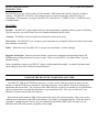
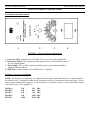
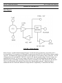
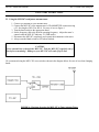
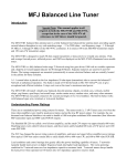
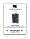
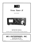
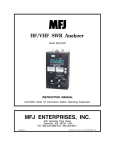
HF 10-160M SWR Analyzer
Model MFJ-207
INSTRUCTION MANUAL
CAUTION: Read All Instructions Before Operating Equipment
MFJ ENTERPRISES, INC.
300 Industrial Park Road
Starkville, MS 39759 USA
Tel: 662-323-5869 Fax: 662-323-6551
VERSION 0B
COPYRIGHT
C
2006 MFJ ENTERPRIS ES , INC.
MFJ-207 Instruction Manual
HF 10-160M SWR Analyzer
MFJ-207 Instruction Manual
HF 10-160M SWR Analyzer
DISCLAIMER
Information in this manual is designed for user purposes only and is not intended to supersede information
contained in customer regulations, technical manuals/documents, positional handbooks, or other official
publications. The copy of this manual provided to the customer will not be updated to reflect current data.
Customers using this manual should report errors or omissions, recommendations for improvements, or other
comments to MFJ Enterprises, 300 Industrial Park Road, Starkville, MS 39759. Phone: (662) 323-5869; FAX:
(662) 323-6551. Business hours: M-F 8-4:30 CST.
MFJ-207 Instruction Manual
HF 10-160M SWR Analyzer
TABLE OF CONTENTS
TOPIC
PAGE
1.
TABLE OF CONTENTS
2
2.
LIST OF FIGURES AND TABLES
2
3.
INTRODUCTION AND FEATURES
3
4.
USES FOR THE MFJ-207
4
5.
SYSTEM CONTROLS AND INDICATORS
5
6.
THEORY OF OPERATION
7
7. MFJ-207 EASY-START INSTRUCTIONS
8.
8
IN CASE OF DIFFICULTY
17
9. TECHNICAL ASSISTANCE
17
APPENDICES
A. ZERO BEATING AGAINST A RECEIVER
14
B. FREQUENCY/SWR PLOTTING CHART
15
C. SWR AT TRANSMITTER VS. SWR AT ANTENNA
16
LIST OF FIGURES
Figure 1
Front Panel Jacks and Controls
5
Figure 2
End Panel Jacks
6
Figure 3
Block Diagram
7
Figure 4
MFJ-207 to Tuner Hook Up
10
Figure 5
Schematic Diagram
13
MFJ-207 Instruction Manual
INTRODUCTION:
HF 10-160M SWR Analyzer
The MFJ-207 gives you a direct readout of your antenna’s SWR without the need for formulas or indirect
readings. The MFJ-207 can also be used to adjust a tuner to match your antenna without the need for
transmitting. The frequency coverage for the MFJ-207 is from below 1.75 MHZ to Above 30 MHZ in 5 user
selectable bands.
FEATURES
Portable – The MFJ-207’s light weight, small size and internal battery capability makes it great for Field Day,
Travel or any time you need to check out a new antenna installation quickly easily.
Accurate – The Bridge Circuit uses precision resistors for utmost in accuracy.
Great Value – The MFJ-207’s low cost puts a great instrument in your hands for those who only need to adjust
their antennas occasionally.
Stable – With built in AGC the MFJ-207 is accurate across the bands. No false readings.
Rugged Construction: Attractive all-metal cabinet, conservative component selection and extensive RF
filtering ensure solid performance for years to come. Fully covered by MFJ’s “No Matter What” one year
limited warranty.
Before attempting to operate your MFJ-207, please read the manual thoroughly. It contains important detail
about setting up your unit to obtain the best performance.
USES FOR THE MFJ-207 HF 10-160M SWR ANALYZER
Your MFJ-207 SWR ANALYZER has many uses. It can be used to find the resonant frequency of your
antenna, to find the SWR of your antenna at a particular frequency, and to find the frequency at which your
antenna has the lowest SWR. You can also use the SWR Analyzer to adjust your antenna to a low SWR and to
adjust an antenna tuner to match the transmitter to your transmission line. You can even find out if your
antenna is resonant on more that one frequency.
Measurement of the antenna’s SWR is done right at the input to the transmission line. There is no need to
climb the tower and measure the SWR at the antenna. Also handy for suspended dipoles. Using the chart in
Appendix C and knowing the line loss for your transmission line and the SWR at the line input, you can
determine the SWR at the antenna, regardless of line length.
MFJ-207 Instruction Manual
HF 10-160M SWR Analyzer
SYSTEM CONTROLS AND INDICATORS
Front Panel Jacks and Controls
1
2
3
4
FIGURE 1: Front Panel Jacks and Controls
1. Power On LED: Instantly know if the MFJ-207 is on or off with this bright LED.
2. Band Select Switch: This 6 position switch turns the power on and selects any one of
five over lapping bands.
3. Tune Control: This variable capacitor instantly sweeps across the desired band to
find that SWR fast and easy.
4. SWR Meter: Direct readout of your SWR from 1:1 to Infinity.
Frequency Coverage of the Bands
NOTE: The frequency coverage may vary slightly from this chart and the label on the cover of the unit and is
for reference only. A frequency counter can be connected to the Freq. Out connector shown in Figure 2 to get a
more accurate reading of the frequency. As an alternative to a frequency counter you can Zero Beat the output
with an HF receiver. See Appendix A.
BAND A:
BAND B:
BAND C:
BAND D:
BAND E:
1.40
2.40
3.90
7.00
14.00
-
2.50
4.50
7.20
14.00
31.00
Mhz
Mhz
Mhz
Mhz
Mhz
MFJ-207 Instruction Manual
HF 10-160M SWR Analyzer
SYSTEM CONTROLS AND INDICATORS
End Panel Jacks
FIGURE 2: End Panel Jacks
1. ANTENNA: This SO-239 Antenna connector allows you to easily hook up your
station’s antenna to the MFJ-207.
2. FREQ. OUT: For additional accuracy you can hook up a frequency counter to this
phono connector or feed the signal over a short piece of wire to your radio and zero
beat against your radio as described in Appendix A.
3. PWR: This 2.1 mm jack allows you to attach a MFJ-1312D AC adapter or feed
power from your station supply.
MFJ-207 Instruction Manual
HF 10-160M SWR Analyzer
THOERY OF OPERATION
Block Diagram
FIGURE 3: Block Diagram
Refer to Figure 3 and the Schematic diagram Figure 5 for this discussion of the theory of operation. RF is
developed in the VCO consisting of L1 through L10 and the associated FETs Q1 and Q2 along with the variable
capacitor. The Band Switch progressively shorts out the inductors as the frequency range is increased. The RF
is then passed to Q3 and amplified. This RF is sensed by D2 and the resulting voltage is fed to U2 where it is
amplified and fed to Q4. Q4 varies the voltage on the source of Q1 and Q2 maintaining the stable RF level.
The Rf then goes to the bridge consisting of three fixed legs consisting of 49.9 Ohm resistors R7, R9 and R21.
The 4th leg of the bridge is the unknown leg which is the Antenna input to the unit. When the bridge is
unbalanced then D1 rectifies the unbalanced voltage and this is amplified by U2 and deflects the meter.
MFJ-207 Instruction Manual
HF 10-160M SWR Analyzer
EASY START INSTRUCTIONS
The MFJ-207 requires the optional MFJ-1312D power supply adapter or a nine-volt transistor battery. If
using a battery with the MFJ-207 ensure it is an ALKALINE nine-volt battery. Additionally you can use a 13.8
volt power supply by connecting a 2.1 mm plug to the cable with the positive wire connected to the center pin
and the ground wire connecter to the outer pin.
To install the battery, remove the screws holding the cover onto the case. Insert the battery into the
battery holder. Tuck the battery snap wires out of the way so they do not interfere with the tuning capacitor
rotation. Reinstall the cover and screws.
I. HOW TO MEASURE THE ANTENNA’S SWR AT A PARTICULAR
FREQUENCY.
1. To check the SWR of your antenna, connect the antenna with a PL-259
connector to the ANTENNA connector on the MFJ-207.
2. If you are using open-wire feedline wire then first you must wire your feedline
to a PL-259 connector and then attach it to the ANTENNA connector of the MFJ-207.
3. Set the BAND switch to the appropriate band.
4. Adjust the FREQUENCY DIAL of the SWR ANALYZER to the frequency at
which you want to check the SWR. For added accuracy connect a frequency
counter to the Freq. Out jack or zero beat against your receiver as described in
Appendix A.
5. Read the SWR from the meter. This is the SWR at the INPUT TO THE
TRANSMISSION LINE looking towards the load (antenna). To determine the
SWR at the antenna refer to Figure **.
6. If the SWR at the SWR Analyzer is 1:1 then the SWR at the antenna is 1:1 at
the selected frequency.
7. Using steps 1 through 5, you can make a plot of the SWR verses
FREQUENCY for your antenna. Just plot the SWR at many different
frequencies. Appendix B shows a SWR vs. FREQUENCY plotting chart. We
suggest you make several copies of the chart so you can use it for several
antennas.
NOTE: It is advisable to take reading on several different bands to determine the frequency at
which the lowest SWR occurs. The SWR can be low at several different frequencies, but there
should only be one frequency that shows the LOWEST SWR. That frequency will be the natural
resonant frequency of that antenna.
MFJ-207 Instruction Manual
HF 10-160M SWR Analyzer
EASY START INSTRUCTIONS
II. HOW TO MEASURE THE FREQUENCY AT WHICH THE ANTENNA HAS
THE LOWEST SWR.
1. Connect the antenna as discussed in step I, 1 or 2.
2. Turn the BAND switch to the appropriate band.
3. Adjust the TUNE control throughout its range until the SWR meter reads its
lowest value. Record the frequency on the frequency meter. Record the SWR
on the meter. For added frequency accuracy hook up a frequency counter or
refer to Appendix A.
4. If you do not obtain a low SWR on any frequency, turn the Band switch to
another band and repeat steps 1-3 above. Don’t be surprised if your antenna
does not show a 1:1 SWR on any frequency. Many antennas can be tuned to
obtain a 1:1 SWR, but will never show a 1:1 SWR without an antenna tuner.
III. Adjust the Antenna for 1:1 SWR.
1. Again connect the antenna as discussed in step I, 1 or 2.
2. Turn the BAND switch to the appropriate band.
3. Turn the Frequency TUNE knob until the pointer is on the frequency at which
you want to tune the antenna.
NOTE: For accuracy, use a frequency counter attached to the FREQ. Output on the SWR
analyzer or zero-beat against your receiver. See Appendix A.
4. Read the SWR on the meter. If the meter reads other than 1:1 SWR then
adjust your antenna until the antenna read 1:1 SWR or the lowest value
obtainable.
NOTE: The MFJ-207 can tell you whether the antenna element are to short or too long.
If you find the resonant frequency of the antenna is lower than the frequency
you wish then the elements are too long. If the resonant frequency is higher
than you want then the elements are too short.
HINT: If you are adjusting an antenna for the first time, it is recommended that you start
with elements a little too long, then shorten to resonance. Again the SWR for
your particular antenna may never get as low as 1:1. Always adjust for the
lowest reading.
MFJ-207 Instruction Manual
HF 10-160M SWR Analyzer
EASY START INSTRUCTIONS
IV. Using the MFJ-207 to adjust an antenna tuner.
1. Connect you antenna to your antenna tuner.
2. Connect the MFJ-207 to the antenna tuner’s TRANSMITTER connector using
a 2-3 foot length of RG-58 or RG-8. For ease of use see figure 4.
3. Turn the band switch to the appropriate band.
4. Set the frequency dial to the desired operating frequency. Adjust the tuner’s
controls until the MFJ-207 indicates 1:1 SWR (nulls).
5. Disconnect the MFJ-207 completely and connect the transmitter to the tuner.
6. Always turn the Band switch to OFF when finished.
CAUTION
Never transmit into or through the MFJ-207. Take the MFJ-207 completely out of
line before transmitting! Damage to your MFJ-207 will result if left in line.
We recommend using the MFJ-1702 coax switch as shown in the diagram below for ease of use when changing
bands.
FIGURE 4: Hook-up for using the MFJ-207 to Tune Antenna Tuner
MFJ-207 Instruction Manual
HF 10-160M SWR Analyzer
EASY START INSTRUCTIONS
WARNING
NEVER TRANSMIT WHILE THE MFJ-1702 COAX SWITCH IS SWITCHED TO A IF
THE TRANSMITTER IS CONNECTED TO B.
SERIOUS DAMAGE TO YOUR RADIO CAN OCCUR.
TRANSMIT ONLY WHEN THE COAX SWITCH IS SWITCHED TO THE
CONNECTOR TO WHICH THE TRANSMITTER IS CONNECTED.
IF THE TRANSMITTER INPUT IS ON B, THEN TRANSMIT ONLY WHEN THE
COAX SWITCH IS IN POSITION B.
IF THE TRANSMITTER INPUT IS ON A, THEN TRANSMIT ONLY WHEN THE
COAX SWITCH IS IN POSITION A.
THE CENTER CONDUCTOR OF THE UNSELECTED COAX POSITION IS
GROUNDED, SO TRANSMITTING INTO B WHILE THE SWITCH IS IN POSITION
WILL CAUSE YOU TO TRANSMIT INTO A DEAD SHORT TO GROUND
MFJ ENTERPRISES, INC, WILL NOT BE LIABLE FOR ANY DAMAGE TO YOUR
RADIO OR OTHER EQUIPMENT DUE TO IMPROPER CONNECTION OR USE OF THE
MFJ-1702 COAX SWITCH
MFJ-207 Instruction Manual
HF 10-160M SWR Analyzer
EASY START INSTRUCTIONS
FACTS ABOUT TRANSMISSION LINES AND LINE LOSS
The MFJ-207 should be connected to the input to the transmission line looking toward the load. You do NOT
have to know the length in wavelength of your transmission line, but you do need to know the length in feet (or
meters) and the loss (in db) for the length of line that you are using at the frequency you are testing. Using the
SWR/Line loss chart in Appendix C you can readily determine the SWR at the antenna. The most important
consideration for any antenna system is probably the loss in the transmission line. The less loss, the better.
Two important points about transmission lines need to be understood:
1. On a LOSSLESS transmission line, the SWR read at the transmitter is the same as the
SWR at the antenna. For any line with loss the SWR is greatest at the antenna and
minimum at the transmitter.
2. Regardless of the losses in the transmission line, if the SWR at the transmitter is 1:1,
then the SWR at the antenna is 1:1, but if there is any SWR at the input to the
transmission line there is a higher SWR at the antenna (assuming anything but a
lossless line). Let’s go through a practical example.
Let’s say you are using RG-58/U which has a loss of 2.3 db at 30 MHz per 100 feet. You are only using 50 feet
of cable, so your loss when matched at the transmitter is 1.15 db at 30 MHz.
Go to Appendix C and find the 1 db loss line which curves up and to the right.
Now assume you are using your MFJ-207 and find the lowest SWR you can get on your antenna is 2.0:1.
Follow the 1.15 db line (between the 1 db line and the 2 db line) down to th point it reads 2.0:1 on the horizontal
axis (SWR at transmitter).
Look at the vertical axis we can see that the point corresponds to an SWR of about 2.5:1 on the vertical axis.
Reading this chart correctly tells us that with 50 feet of RG-58/U that has a loss of 2.3 db per 100 feet at 30
MHz and a line input SWR of 2.0:1, the SWR at the antenna is 2.5:1.
By the way, the 2.0:1 SWR at the load only adds about .225 db of loss to the already matched 1.4 db of loss foe
a total loss of 1.625 db. (See ARRL Antenna book)
MFJ-207 Instruction Manual
HF 10-160M SWR Analyzer
Figure 5: MFJ-207 Schematic Diagram
MFJ-207 Instruction Manual
HF 10-160M SWR Analyzer
APPENDIX A
HOW TO ZERO BEAT THE MFJ-207 AGAINST THE RECEIVER
The Freq. Out jack on the MFJ-207 has a sine wave output which can be used to accurately check the frequency
at which the MFJ-207 is adjusted to.
To zero-beat against the receiver, loosely couple a wire from the RCA jack (Freq. Out) to the antenna connector
on your radio.
First, try a small length of wire from the Freq. Out connector of the MFJ-207. Just leave it dangling free, not
touching the Antenna input of the receiver. Place the far end of the wire near the receiver but do not connect it
to the receiver’s input unless you simply cannot hear the signal at all. The output of the MFJ-207 is a high level
and damage to the front end of some radios may occur with a direct connection, so you assume all risks in
making a direct connection.
Turn the radio on and tune to the frequency in question. For example, if you want to check your 40 meter
dipole on 7.235 MHz, set the radio for 7.235 MHz. Turn the RF gain and the Audio of you radio down as the
level of the MFJ-207 is strong. Put your radio in the CW mode. If you have a BFO adjustment on your radio,
be sure to set the BFO to ON and to 0 (zero).
Set the MFJ-207 to band C. Adjust the tune dial on the MFJ-207 until you start hearing a tone in the radio’s
speaker. As you slowly turn the TUNE dial, the frequency will start at a very high pitch, and then decrease to
zero pitch. The point where the tone goes to zero hertz is the “zero-beat”. That means the MFJ-207 is set
exactly to the setting on the radio.
Now make a note of where the dial is set on the MFJ-207 so you can re-set the frequency if you accidentally
bump the TUNE control.
You can now disconnect the wire and re-connect the antenna to the MFJ-207.
MFJ-207 Instruction Manual
HF 10-160M SWR Analyzer
APPENDIX B
FREQUENCY/SWR PLOTTING CHART
MFJ-207 Instruction Manual
HF 10-160M SWR Analyzer
APPENDIX C
SWR at Transmitter Vs. SWR at Antenna
MFJ-207 Instruction Manual
HF 10-160M SWR Analyzer
TECHNICIAL ASSISTANCE
IN CASE OF DIFFICULTY
[ ] Unit will not turn on – Ensure you have a fresh battery in the unit or your power supply is plugged in all
the way to the unit.
[ ] Unit drifts excessively – This is normally caused by low battery voltage. Replace the battery with a fresh
battery.
[ ] Meter never moves off full scale – Ensure your antenna is properly connected to the unit.
TECHNICAL ASSISTANCE
If you have any problem with this unit first check the appropriate section of this manual. If the manual does not
reference your problem or is your problem is not solved by reading the manual, you may call MFJ Technical
Service at 662-323-0549 or the MFJ Factory at 662-323-5869. You will be best helped if you have your unit,
manual and all information on your station handy so you can answer any questions the technician may ask.
You can also send questions by mail to MFJ Enterprises, Inc., 300 Industrial Park Road, Starkville, MS 39759;
by Facsimile (FAX) to 662-323-6551; or by email to [email protected]. Send a complete
description of your problem, an explanation of exactly how you are using your unit , and a complete description
of your station.
MFJ-207 Instruction Manual
HF 10-160M SWR Analyzer
MFJ-207 Instruction Manual
HF 10-160M SWR Analyzer
FULL 12-MONTH WARRANTY
MFJ Enterprises, Inc. warrants to the original owner of this product, if manufactured by MFJ Enterprises, Inc.
and purchased from an authorized dealer or directly from MFJ Enterprises, Inc. to be free from defects in
material and workmanship for a period of 12 months from date of purchase provided the following terms of this
warranty are satisfied.
1.
The purchaser must retain the dated proof-of-purchase (bill of sale, canceled check, credit card or money
order receipt, etc.) describing the product to establish the validity of the warranty claim and submit the original or
machine reproduction of such proof of purchase to MFJ Enterprises, Inc. at the time of warranty service. MFJ
Enterprises, Inc. shall have the discretion to deny warranty without dated proof-of-purchase. Any evidence of
alteration, erasure, of forgery shall be cause to void any and all warranty terms immediately.
2.
MFJ Enterprises, Inc. agrees to repair or replace at MFJ's option without charge to the original owner any
defective product provided the product is returned postage prepaid to MFJ Enterprises, Inc. with a personal check,
cashiers check, or money order for $10.00 covering postage and handling.
3.
MFJ Enterprises, Inc. will supply replacement parts free of charge for any MFJ product under warranty
upon request. A dated proof of purchase and a $8.00 personal check, cashiers check, or money order must be
provided to cover postage and handling.
4.
This warranty is NOT void for owners who attempt to repair defective units. Technical consultation is
available by calling (662) 323-5869.
5.
This warranty does not apply to kits sold by or manufactured by MFJ Enterprises, Inc.
6.
Wired and tested PC board products are covered by this warranty provided only the wired and tested PC
board product is returned. Wired and tested PC boards installed in the owner's cabinet or connected to switches,
jacks, or cables, etc. sent to MFJ Enterprises, Inc. will be returned at the owner's expense un-repaired.
7.
Under no circumstances is MFJ Enterprises, Inc. liable for consequential damages to person or property
by the use of any MFJ products.
8.
Out-of-Warranty Service: MFJ Enterprises, Inc. will repair any out-of-warranty product provided the
unit is shipped prepaid. All repaired units will be shipped COD to the owner. Repair charges will be added to the
COD fee unless other arrangements are made.
9.
This warranty is given in lieu of any other warranty expressed or implied.
10.
MFJ Enterprises, Inc. reserves the right to make changes or improvements in design or manufacture
without incurring any obligation to install such changes upon any of the products previously manufactured.
11.
All MFJ products to be serviced in-warranty or out-of-warranty should be addressed to MFJ Enterprises,
Inc., 300 Industrial Park Rd, Starkville, Mississippi 39759, USA and must be accompanied by a letter
describing the problem in detail along with a copy of your dated proof-of-purchase and a telephone number.
12.
state.
This warranty gives you specific rights, and you may also have other rights, which vary from state to