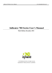
1
MV electrical network management
Easergy range
T200 & Flair 200C
& R200-ATS100
MV substation control and monitoring units
IEC 870-5-104 communication
Appendix to the User Manual
T200, Flair 200C, R200
Contents
1.
ABOUT THE BOOK ..................................................................................................................................... 3
2.
IEC 60 870-5-104 ......................................................................................................................................... 4
2.1. PRESENTATION .............................................................................................................................................. 4
2.2. INTEROPERABILITY TABLE .............................................................................................................................. 5
2.3. PROTOCOL CHARACTERISTICS .....................................................................................................................17
Transmission pile size ...................................................................................................................................17
Possible data-flow .........................................................................................................................................17
Configuration .................................................................................................................................................17
R200-ATS100 Configuration .........................................................................................................................19
2.4. BIBLIOGRAPHY .............................................................................................................................................20
3.
OBJECT ADDRESSING ............................................................................................................................21
2
NT00199-EN-08
T200, Flair 200C, R200
About the book
1. About the book
Presentation
Document scope
This manual describes the IEC 870-5-104 protocol implementation on T200 and
Flair 200C products
Application field
Apply to T200 and Flair 200C products
Document’s
evolutions
V1.0: Creation of IEC 870-5-104 user’s manual.
V1.1: Flair 200C added
V1.2: T200 V3.3 release :
•
Redundancy until 8 connections
•
Dating validity through SNTP
V1.3 : Interoperability table update, add of Set point Commands
Related
documents
User comments
NT00199-EN-08
3
T200, Flair 200C, R200
IEC 60 870-5-104
2. IEC 60 870-5-104
2.1. Presentation
Definition
The IEC 60870-5-104 protocol is derived from the IEC 60870-5-101 protocol. This one was
specified on a serial link whereas IEC 60870-5-104 is an application running on a TCP/IP layer
Main differences between the 2 protocols are :
•
management of the TCP/IP layer interface (APCI)
•
new functions (ASDU) that have been added.
IEC 60870-5-101 protocol specifies frame format and the IEC 60870-5-104 protocol specifies
the frame format of the transport interface (APCI) as well as exchanging rules between two
equipments. Thus the equipment can communicate with a supervisor (or another equipment).
ISO Model
Transmission
mode
Data
Features
Interoperability
The IEC 60870-5-104 protocol is based on TCP/IP transport profile.
It is located exclusively on layer 7 of the ISO model but can be considered as made of two
sub-layers :
•
Transport interface : APCI (Application Protocol control Information)
•
ASDU from IEC 60870-5-101 and IEC 60870-5-104 selection
The protocol is client – server application. The equipment is acting as a server, and the
supervisor (SCADA) is acting as the client and connect the server.
The IEC 870-5-104 protocol specifies the data that can be exchanged and the format used for
transmission. Among the different data types provided by the protocol, we can quote:
•
signalisations (singles or doubles),
•
measured values (with different formats),
•
integrated totals,
•
commands,
•
parameters.
Features are associated to particular data types. For example :
•
general interrogation,
•
clock synchronisation,
•
events transmission (time-stamped or not),
•
integrated totals specific treatment (freezing, reset,…)
•
command transmission modes (select and execute mode or direct mode)
•
parameters activation.
Depending on their specifications, connected equipments do not use the same data types or
features define by the protocol
In order to evaluate the compatibility between different equipments that should be connected,
each manufacturer provides a document, called Interoperability table, where the used data and
features are shown and detailed.
4
NT00199-EN-08
T200, Flair 200C, R200
IEC 60 870-5-104
2.2. Interoperability Table
REMARKS
This companion standard presents sets of parameters and alternatives from which subsets
must be selected to implement particular telecontrol systems. Certain parameter values, such
as the choice of “structured“ or “unstructured“ fields of the INFORMATION OBJECT
ADDRESS of ASDUs represent mutually exclusive alternatives. This means that only one
value of the defined parameters is admitted per system. Other parameters, such as the listed
set of different process information in command and in monitor direction allow the specification
of the complete set or subsets, as appropriate for given applications. This clause summarizes
the parameters of the previous clauses to facilitate a suitable selection for a specific
application. If a system is composed of equipment stemming from different manufacturers, it is
necessary that all partners agree on the selected parameters. The interoperability list is
defined as in IEC 60870-5-101 and extended with parameters used in this standard. The text
descriptions of parameters which are not applicable to this companion standard are strikethrough (corresponding check box is marked black).
System or device
system-specific parameter, indicate the station’s function by marking one of the following with
‘X’
System definition
Controlling station definition (MASTER)
X
Controlled station definition (SLAVE)
Network
Configuration
network-specific parameter, all configurations that are used are to be marked ‘X’
Point-to-point
Multipoint-party line
Multiple point-to-point
Multipoint-star
Physical layer
Transmission
speed
Unbalanced interchange
Circuit V.24/V.28
Standard
network-specific parameter, all interfaces and data rates that are used are to be marked ‘X’
Control direction
Unbalanced interchange
Circuit V.24/V.28
Recommended if >1200bit/s
Balanced interchange
Circuit X.24/X.27
100 bit/s
2 400 bit/s
2 400 bit/s
56 000 bit/s
200 bit/s
4 800 bit/s
4 800 bit/s
64 000 bit/s
300 bit/s
9 600 bit/s
9 600 bit/s
600 bit/s
19 200 bit/s
1 200 bit/s
38 400 bit/s
Transmission
speed
NT00199-EN-08
Monitor direction
5
T200, Flair 200C, R200
Unbalanced interchange
Circuit V.24/V.28
Standard
IEC 60 870-5-104
Unbalanced interchange
Circuit V.24/V.28
Recommended if >1 200bit/s
Balanced interchange
Circuit X.24/X.27
100 bit/s
2 400 bit/s
2 400 bit/s
56 000 bit/s
200 bit/s
4 800 bit/s
4 800 bit/s
64 000 bit/s
300 bit/s
9 600 bit/s
9 600 bit/s
600 bit/s
19 200 bit/s
1 200 bit/s
38 400 bit/s
LINK LAYER
network-specific parameter, all options that are used are to be marked ‘X’. Specify the
maximum frame length. If a non-standard assignment of class 2 messages is implemented for
unbalanced transmission, indicate the Type ID and COT of all messages assigned to class 2.
Frame format FT 1.2, single character 1 and the fixed time out interval are used exclusively in
this companion standard.
Link transmission procedure
Address field of the link
Balanced transmission
Not present (balanced transmission only)
Unbalanced transmission
One octet
Frame length
Two octets
maximum length L (number of octets)
Structured
Unstructured
When using an unbalanced link layer, the following ASDU types are returned in class 2 messages (low
priority) with the indicated causes of transmission:
The standard assignment of ASDUs to class 2 messages is used as follows:
Type identification
Cause of transmission
9, 11, 13, 21
<1>
A special assignment of ASDUs to class 2 messages is used as follows:
Type identification
Cause of transmission
NOTE : In response to a class 2 poll, a controlled station may respond with class 1 data when
there is no class 2 data available
6
NT00199-EN-08
T200, Flair 200C, R200
IEC 60 870-5-104
Application layer
TRANSMISSION
MODE FOR
APPLICATION D
ATA :
Mode 1 (Least significant octet first), as defined in clause 4.10 of IEC 60870-5-4, is used
exclusively in this companion standard..
Common
Address of
ASDU
system-specific parameter, all configurations that are used are to be marked ‘X’
X
One octet
Information object
address
system-specific parameter, all configurations that are used are to be marked ‘X’
One octet
Structured
X
Two octets
X
Two octets
Unstructured
Three octets
Cause of
transmission
system-specific parameter, all configurations that are used are to be marked ‘X’
X
One octet
Two octets (with originator address)
originator address is set to zero
Length of APDU
system-specific parameter, specify the maximum length of the APDU per system
The maximum length of the APDU is 253 (default). The maximum length may be reduced by
the system.
253
Maximum length of APDU per system
Selection of standard ASDUs
station-specific parameter, mark each Type ID ‘X’ if it is only used in the standard direction, ‘R’
if only used in
the reverse direction, and ‘B’ if used in both directions
PROCESS
INFORMATION
IN MONITOR
DIRECTION
X
<1>
<2>
X
<3>
<4>
<5>
NT00199-EN-08
:
=
:
=
:
=
:
=
:
=
Single-point information
M_SP_NA_1
Single-point information with time tag
M_SP_TA_1
Double-point information
M_DP_NA_1
Double-point information with time tag
M_DP_TA_1
Step position information
M_ST_NA_1
7
T200, Flair 200C, R200
<6>
<7>
<8>
X
<9>
<10>
X
<11>
<12>
X
<13>
<14>
X
<15>
<16>
<17>
<18>
<19>
<20>
<21>
X
<30>
X
<31>
<32>
<33>
X
<34>
X
<35>
X
<36>
X
<37>
<38>
<39>
<40>
:
=
:
=
:
=
:
=
:
=
:
=
:
=
:
=
:
=
:
=
:
=
:
=
:
=
:
=
:
=
:
=
:
=
:
=
:
=
:
=
:
=
:
=
:
=
:
=
:
=
:
=
IEC 60 870-5-104
Step position information with time tag
M_ST_TA_1
Bit string of 32 bit
M_BO_NA_1
Bit string of 32 bit with time tag
M_BO_TA_1
Measured value, normalized value
M_ME_NA_1
Measured value, normalized value with time tag
M_ME_TA_1
Measured value, scaled value
M_ME_NB_1
Measured value, scaled value with time tag
M_ME_TB_1
Measured value, short floating point value
M_ME_NC_1
Measured value, short floating point value with time tag
M_ME_TC_1
Integrated totals
M_IT_NA_1
Integrated totals with time tag
M_IT_TA_1
Event of protection equipment with time tag
M_EP_TA_1
Packed start events of protection equipment with time tag
M_EP_TB_1
Packed output circuit information of protection equipment with time tag
M_EP_TC_1
Packed single-point information with status change detection
M_PS_NA_1
Measured value, normalized value without quality descriptor
M_ME_ND_1
Single-point information with time tag CP56Time2a
M_SP_TB_1
Double-point information with time tag CP56Time2a
M_DP_TB_1
Step position information with time tag CP56Time2a
M_ST_TB_1
Bit string of 32 bit with time tag CP56Time2a
M_BO_TB_1
Measured value, normalized value with time tag CP56Time2a
M_ME_TD_1
Measured value, scaled value with time tag CP56Time2a
M_ME_TE_1
Measured value, short floating point value with time tag CP56Time2a
M_ME_TF_1
Integrated totals with time tag CP56Time2a
M_IT_TB_1
Event of protection equipment with time tag CP56Time2a
M_EP_TD_1
Packed start events of protection equipment with time tag CP56Time2a
M_EP_TE_1
:
Packed output circuit information of protection equipment with time tag CP56Time2a
=
M_EP_TF_1
Either the ASDUs of the set <2>, <4>, <6>, <8>, <10>, <12>, <14> >, <16>, <17>,
<18>, <19> or of the set <30> – <40> are used
station-specific parameter, mark each Type ID ‘X’ if it is only used in the standard direction, ‘R’
if only used in
the reverse direction, and ‘B’ if used in both directions
Process
information in
control direction
X
<45>
X
<46>
<47>
X
<48>
X
<49>
8
:
=
:
=
:
=
:
=
:
=
Single command
C_SC_NA_1
Double command
C_DC_NA_1
Regulating step command
C_RC_NA_1
Set point command, normalized value
C_SE_NA_1
Set point command, scaled value
C_SE_NB_1
NT00199-EN-08
T200, Flair 200C, R200
X
:
=
:
=
:
=
:
=
:
=
:
=
:
=
:
=
:
=
<50>
<51>
X
<58>
X
<59>
<60>
X
<61>
X
<62>
X
<63>
<64>
IEC 60 870-5-104
Set point command, short floating point value
C_SE_NC_1
Bit string of 32 bit
C_BO_NA_1
Single command with time tag CP56Time 2a
C_SC_TA_1
Double command with time tag CP56Time 2a
C_DC_TA_1
Regulating step command with time tag CP56Time 2a
C_RC_TA_1
Set point command, normalized value with time tag CP56Time 2a
C_SE_TA_1
Set point command, scaled value with time tag CP56Time 2a
C_SE_TB_1
Set point command, short floating point value with time tag CP56Time 2a
C_SE_TC_1
Bit string of 32 bit with time tag CP56Time 2a
C_BO_TA_1
Either the ASDUs of the set <45> – <51>or of the set <58>-<64> are used.
System
information in
monitor direction
X
<70>
station-specific parameter, mark ‘X’ if used
:= End of initialization
System
information in
control direction
M_EI_NA_1
station-specific parameter, mark ‘X’ if used
X
<100>
:= Interrogation command
C_IC_NA_1
X
<101>
:= Counter interrogation command
C_CI_NA_1
X
<102>
:= Read command
C_RD_NA_1
X
<103>
:= Clock synchronization command
C_CS_NA_1
<104>
: Test command
=
C_TS_NA_1
<105>
:= Reset process command
C_RP_NA_1
<106>
:= Delay acquisition command
C CD NA 1
<107>
:= Test command with time tag CP56time2a
C_TS_TA_1
X
Parameter in
control direction
station-specific parameter, mark ‘X’ if used
<110>
:= Parameter of measured value, normalized value
P_ME_NA_1
<111>
:= Parameter of measured value, scaled value
P_ME_NB_1
<112>
:= Parameter of measured value, short floating point value
P_ME_NC_1
<113>
:= Parameter activation
P_AC_NA_1
NT00199-EN-08
9
IEC 60 870-5-104
T200, Flair 200C, R200
File Transfer
station-specific parameter, mark each Type ID ‘X’ if it is only used in the standard direction, ‘R’
if only used in
the reverse direction, and ‘B’ if used in both directions
<120>
:= File ready
F_FR_NA_1
<121>
:= Section ready
F_SR_NA_1
<122>
:= Call directory, select file, call file, call section
F_SC_NA_1
<123>
:= Last section, last segment
F_LS_NA_1
<124>
:= Ack file, ack section
F_AF_NA_1
<125>
:= Segment
F_SG_NA_1
<126>
:= Directory (blank or X, only available in monitor (standard) direction)
F_DR_TA_1
Type identifier
and causes of
transmission
assignment
station-specific parameters
Shaded boxes are not required.
Black boxes are not permitted in this companion standard
Blank: functions or ASDU not used.
Mark Type Identification/Cause of transmission combinations:
‘X’ if only used in the standard direction
‘R’ if only used in the reverse direction
‘B’ if used in both directions
Type Identification
Cause of transmission
1
<1>
<2>
<3>
<4>
<5>
<6>
<7>
<8>
<9>
<10>
<11>
<12>
<13>
<14>
<15>
<16>
<17>
<18>
<19>
<20>
<21>
<30>
<31>
<32>
<33>
10
M_SP_NA_1
M_SP_TA_1
M_DP_NA_1
M_DP_TA_1
M_ST_NA_1
M_ST_TA_1
M_BO_NA_1
M_BO_TA_1
M_ME_NA_1
M_ME_TA_1
M_ME_NB_1
M_ME_TB_1
M_ME_NC_1
M_ME_TC_1
M_IT_NA_1
M_IT_TA_1
M_EP_TA_1
M_EP_TB_1
M_EP_TC_1
M_PS_NA_1
M_ME_ND_1
M_SP_TB_1
M_DP_TB_1
M_ST_TB_1
M_BO_TB_1
2
3
4
5
X
X
20 à
36
X
X
X
X
X
X
X
X
X
X
X
X
X
X
X
X
X
X
X
6
7
8
9
10
11
12
13
37 à
41
44
45
46
47
X
X
X
NT00199-EN-08
T200, Flair 200C, R200
<34>
M_ME_TD_1
<35>
M_ME_TE_1
<36>
M_ME_TF_1
<37>
M_IT_TB_1
<38>
M_EP_TD_1
<39>
M_EP_TE_1
<40>
M_EP_TF_1
<45>
C_SC_NA_1
<46>
C_DC_NA_1
<47>
C_RC_NA_1
<48>
C_SE_NA_1
<49>
C_SE_NB_1
<50>
C_SE_NC_1
<51>
C_BO_NA_1
<58>
C_SC_TA_1
<59>
C_DC_TA_1
<60>
C_RC_TA_1
<61>
C_SE_TA_1
<62>
C_SE_TB_1
<63>
C_SE_TC_1
<64>
C_BO_TA_1
<70>
M_EI_NA_1
<100
C_IC_NA_1
>
<101
C_CI_NA_1
>
<102
C_RD_NA_1
>
<103
C_CS_NA_1
>
<104
C_TS_NA_1
>
<105
C_RP_NA_1
>
C_CD_NA_1
<106
>
<107
C_TS_TA_1
>
<110
P_ME_NA_1
>
<111
P_ME_NB_1
>
<112
P_ME_NC_1
>
<113
P_AC_NA_1
>
<120
F_FR_NA_1
>
<121
F_SR_NA_1
>
<122
F_SC_NA_1
>
<123
F_LS_NA_1
>
<124
F_AF_NA_1
>
<125
F_SG_NA_1
>
a)
<126
F_DR_TA_1
>
a)
Blank or X only
NT00199-EN-08
X
X
X
X
IEC 60 870-5-104
X
X
X
X
X X X X
X X X X
X
X
X X X X
X X X X
X X X X
X
X
X
X X X X
X X X X
X
X
X X X X
X X X X
X X X X
X
X
X
X X X X
X
X X
X
X
X
X X
X X
11
T200, Flair 200C, R200
IEC 60 870-5-104
Basic application functions
Station
initialization
X
station-specific parameter, mark ‘X’ if function is used
Remote initialization
Cyclic data
transmission
X
station-specific parameter, mark ‘X’ if function is only used in the standard direction, ‘R’ if only
used in the reverse direction, and ‘B’ if used in both directions
Cyclic data transmission
Read procedure
X
station-specific parameter, mark ‘X’ if function is only used in the standard direction, ‘R’ if only
used in the reverse direction, and ‘B’ if used in both directions
Read Procedure
station-specific parameter, mark ‘X’ if function is used
Spontaneous
transmission
X
Spontaneous transmission
Double
station-specific parameter, mark each information type ‘X’ where both a Type ID without time
transmission of
and corresponding Type ID with time are issued in response to a single spontaneous change
information
of a monitored object.
objects with cause
of transmission
spontaneous
The following type identifications may be transmitted in succession caused by a
single status change of an information object. The particular information object
addresses for which double transmission is enabled are defined in a projectspecific list
Single-point Information M_SP_NA_1, M_SP_TA_1, M_SP_TB_1 and M_PS_NA_1
Diouble-point Information M_DP_NA_1, M_DP_TA_1 and M_DP_TB_1
Step position information M_ST_NA_1, M_ST_TA_1 and M_ST_TB_1
Bitstring of 32 bit M_BO_NA_1, M_BO_TA_1 and M_BO_TB_1 (if defined for a specific project)
Measured value, normalized value M ME NA 1, M ME TA 1, M ME ND 1 and M ME TD 1
Measured value, scaled value M ME NB 1, M ME TB 1 and M ME TE 1
Measured value, short floating point number M_ME_NC_1, M_ME_TC_1 and M_ME_TF_1
12
NT00199-EN-08
T200, Flair 200C, R200
IEC 60 870-5-104
Station
Interrogation
station-specific parameter, mark ‘X’ if function is only used in the standard
direction, ‘R’ if only used in the reverse direction, and ‘B’ if used in both
directions
Clock
synchronization
station-specific parameter, mark ‘X’ if function is only used in the standard
direction, ‘R’ if only used in the reverse direction, and ‘B’ if used in both
directions.
X
X
global
group 1
group 7
group 13
group 2
group 8
group 14
group 3
group 9
group 15
group 4
group 10
group 16
group 5
group 11
group 6
group 12
Clock synchronization
Command
transmission
X
Information Object Addresses assigned to each group must be shown in a separate
table
station-specific parameter, mark ‘X’ if function is only used in the standard
direction, ‘R’ if only used in the reverse direction, and ‘B’ if used in both
directions.
Direct command transmission
Direct set point command transmission
X
Select and execute command
Select and execute set point command
C_SE ACTTERM used
NT00199-EN-08
13
T200, Flair 200C, R200
Transmission of
integrated totals
X
IEC 60 870-5-104
station-specific parameter, mark ‘X’ if function is only used in the standard direction, ‘R’ if only
used in the reverse direction, and ‘B’ if used in both directions
Mode A: Local freeze with spontaneous transmission
Mode B: Local freeze with counter interrogation
Mode C: Freeze and transmit by counter-interrogation commands
Mode D: Freeze by counter-interrogation command, frozen values reported spontaneously
Counter read
Counter freeze without reset Counter freeze with reset
Counter reset
X
General request counter
Request counter group 1
Request counter group 2
Request counter group 3
Request counter group 4
Parameter loading
station-specific parameter, mark ‘X’ if function is only used in the standard direction, ‘R’ if only
used in the reverse direction, and ‘B’ if used in both directions
Threshold value
Smoothing factor
Low limit for transmission of measured values
High limit for transmission of measured values
Parameter
activation
station-specific parameter, mark ‘X’ if function is only used in the standard
direction, ‘R’ if only used in the reverse direction, and ‘B’ if used in both
directions
Act/deact of persistent cyclic or periodic transmission of the addressed object
Test procedure
station-specific parameter, mark ‘X’ if function is only used in the standard
direction, ‘R’ if only used in the reverse direction, and ‘B’ if used in both
directions
Test Procedure
File transfer
14
station-specific parameter, mark ‘X’ if function is used
NT00199-EN-08
T200, Flair 200C, R200
IEC 60 870-5-104
File transfer in
monitor direction
Transparent file
Transmission of disturbance data of protection equipment
Transmission of sequences of events
Transmission of sequences of recorded analog values
File transfer in
control direction
Transparent file
Background scan
station-specific parameter, mark ‘X’ if function is only used in the standard
direction, ‘R’ if only used in the reverse direction, and ‘B’ if used in both
directions
Background scan
Acquisition of
transmission delay
Acquisition of transmission delay
Definition of timeouts
Parameter
t0
t1
Default value
30 s
15 s
t2
10 s
t3
20 s
Remarks
Time-out of connection establishment
Maximum time to wait until the Supervisor
indicates that it has correctly received the
frame previously send by the unit. If the
confirmation is not received, the session is
closed.
Maximum time to wait before to send a S
frame confirmation for frames received
from the Supervisor. (T2 < T1)
If no data transfers occur during a certain
period of time, a frame will be send to test
the link. (T3>T1)
Selected value
30 s
Configurable
Configurable
Configurable
Maximum range of values k: 1 to 32767 (215-1) APDUs, accuracy 1 APDU
Maximum range of values w: 1 to 32767 APDUs, accuracy 1 APDU (Recommendation: w
should not exceed two-thirds of k).
Because of memory limitations, k and w are limited to 20 APDUs with w < k
NT00199-EN-08
15
T200, Flair 200C, R200
IEC 60 870-5-104
Port Number
Parameter
Port number
8
Remark
configurable
Number N of redundancy group connections used. (T200 only)
RFC 2200 suite
16
Value
2404
RFC 2200 is an official Internet Standard which describes the state of standardization of
protocols used in the Internet as determined by the Internet Architecture Board (IAB). It offers
a broad spectrum of actual standards used in the Internet. The suitable selection of documents
from RFC 2200 defined in this standard for given projects has to be chosen by the user of this
standard.
NT00199-EN-08
T200, Flair 200C, R200
2.3.
IEC 60 870-5-104
Protocol Characteristics
Transmission pile
size
Transmission pile is linked to the number of events that can be kept in memory as long as the
SCADA has not read them. This is important when communication is lost or when the events
flow is bigger than the protocol data-flow. In all cases, those events are lost in case of
equipment shut down.
The equipment deals with digitals information (TOR), integrated totals or measured values.
The size of the transmission pile is 350 events for each type
Possible data-flow
With a point to point connection on an 10/100Mb/s Ethernet link, the protocol is able to
transmit 1000 events per seconds.
WARNING : Performances are dependent on the Ethernet network.
Configuration
NT00199-EN-08
The list of available parameters is the following :
17
T200, Flair 200C, R200
IEC 60 870-5-104
Protocol 60 870-5-104 Configuration page
Paragraph
Parameter
Configuration
limits
0.0.0.0 to
SCADAs
IP_client1 à
255.255.255.255
Adresses
IP_client8
(T200 only)
General
protocol
parameters
Interoperability
(Transmission)
Interoperability
(Application)
Comments
255.255.255.25
5
The product allowed until 8 redundancy
connections. Incoming addresses can be
filtered
0.0.0.0 means that no incoming connections
are allowed.
255.255.255.255 means that all incoming
connections are allowed.
Common ASDU
Address
1 to 65534
1
The equipment has a unique database for
the all variables (only one ASDU address)
TCP/IP Port
1 to 65534
2404
Frame Length
(max)
K
4 to 253
253
1 to 20
12
W
1 to 20
8
T1
1 to 255
60 s
T2
1 to 255
20 s
T3
1 to 255
120 s
Measured value
Adjusted or
Normalized or
Floating
Yes or No
Adjusted
IEC 870-5-104 standard specifies that the
number must be 2404. It is here configurable
to be able to use any TCP/IP network.
Maximum length of APDU (Application
Protocol Data Unit)
Number of frame that the unit can send
without receiving acknowledged from the
Supervisor.
Number of frames that the unit can receive
without
sending
acknowledgement.
(W < 2/3K)
Maximum time to wait until the Supervisor
indicates that it has correctly received the
frame previously send by the unit. If the
confirmation is not received, the session is
closed.
Maximum time to wait before to send a S
frame confirmation for frames received from
the Supervisor. (T2 < T1)
If no data transfers occur during a certain
period of time, a frame will be send to test
the link. (T3>T1)
Define measured value format to the
SCADA
Use SNTP clock
validity
Yes or No
No
Clock validity
0 to 86400 s
3600 s
Command type
Direct or
Selection and
execution
1 to 60 s
Direct
Select Timeout
0 to 60 s
5s
Single-point
dating
Double-point
dating
Yes or No
Yes
Yes or No
Yes
End of init
Transmission
Command
timeout
18
Default
Configuration
Yes
5s
Send or not a frame type M_EI_NA_1 once
the communication is established with the
SCADA
For signalization with time tag, the validity /
invalidity of the dating can be given by SNTP
synchronization by checking the option.
Activation delay of the « clock validity » bit
in CP56Time2a format after a
synchronization made by the protocol
60870-5-104.
0 correspond to an ‘always valid’ clock.
Command by the protocol mode
In case of command with time (C_SC_TA_1
or C_DC_TA_1), define the validity delay of
the command compare to the frame date
and time
In Selection and execution mode, define the
maximum delay between the selection frame
and the execution frame
0 correspond to an infinite delay
Specify if spontaneous single-points events
must be time-stamped or not.
Specify if spontaneous double-points events
must be time-stamped or not.
NT00199-EN-08
T200, Flair 200C, R200
IEC 60 870-5-104
Integrated totals
dating
Measured value
dating
Yes or No
Yes
Yes or No
Yes
Cyclic Measured
value dating
Yes or No
Yes
Specify if spontaneous integrated totals
events must be time-stamped or not.
Specify if spontaneous measured value
events (threshold, dead band) must be timestamped or not.
Specify if cyclic measured value events must
be time-stamped or not.
R200-ATS100 Configuration
The protocol configuration can be found under Settings \ SCADA communication \
Protocol.
The parameters are similar to T200/F200C, and described in previous paragraph.
•
TCP port configuration:
The TCP server port can be modified under Settings \ SCADA communication \ Ethernet Port
NT00199-EN-08
19
T200, Flair 200C, R200
IEC 60 870-5-104
2.4. Bibliography
IEC101 Standard
The international standard has been specified by the International Electro technical
Commission mainly in following documents:
•
•
•
•
•
•
•
IEC 60870-5-1: 1990, Telecontrol equipment and systems – Part 5: Transmission
protocols – Section 1: Transmission frame formats
IEC 60870-5-2: 1992,
Telecontrol equipment and systems – Part 5: Transmission
protocols – Section 2: Link transmission procedures
IEC 60870-5-3: 1992,
Telecontrol equipment and systems – Part 5: Transmission
protocols – Section 3: General structure of application data
IEC 60870-5-4: 1993,
Telecontrol equipment and systems – Part 5: Transmission
protocols – Section 4: Definition and coding of application information element
IEC 60870-5-5: 1993,
Telecontrol equipment and systems – Part 5: Transmission
protocols – Section 5: Basic application functions
IEC 60870-5-101: 2003, Telecontrol equipment and systems – Part 5-101: Transmission
protocols – Companion standard for basic telecontrol tasks
IEC 60870-5-104: 2000, Telecontrol equipment and systems – Part 5-104: Transmission
protocols – Network access for IEC 60870-5-101 using standard transport profiles
Previous documents use references to others useful documents with the following references :
•
•
•
•
•
•
•
•
•
20
IEC 60050(371): 1984,
International Electro technical Vocabulary (IEV) – Chapter
371: Telecontrol
IEC 60870-1-1: 1988,
Telecontrol equipment and systems – Part 1: General
considerations – Section 1: General principles
IEC 60870-5-103: 1997,
Telecontrol equipment and systems – Part 5-103:
Transmission protocols – Companion standard for the informative interface of protection
equipment
OSI/IEC 8824-1: 2000,
Information technology – Abstract Syntax Notation One
(ASN.1): Specification of basic notation
ITU-T V.24: 2000,
List of definitions for interchange circuits between data terminal
equipment (DTE) and data circuit-terminating equipment (DCE)
ITU-T V.28: 1993,
Electrical characteristics for unbalanced double-current interchange
circuits
ITU-T X.24: 1988,
List of definitions for interchange circuits between Data Terminal
Equipment (DTE) and Data Circuit-terminating Equipment (DCE) on public data networks
ITU-T X.27: 1996,
Electrical characteristics for balanced double-current interchange
circuits operating at data signalling rates up to 10 Mbit/s
IEEE 754: 1985,
Binary floating-point arithmetic
NT00199-EN-08
T200, Flair 200C, R200
IEC 60 870-5-104
3. Object addressing
The table of information object addresses for IEC 870-5-104 protocol is exactly the same as the one of the IEC
870-5-101 protocol.
For the full list of these table addresses, consult the IEC 870-5-101 protocol user's manual (ref. NT00156-ENxx).
NT00199-EN-08
21
T200 & Flair 200C
22
Personal notes
NT00199-EN-08
T200 & Flair 200C
NT00199-EN-08
Personal notes
23
Schneider Electric Industries SAS
As standards, specifications and designs change from time to time,
please ask for confirmation of the information given in this publication.
Schneider Electric Telecontrol
839 chemin des Batterses
Z.I. Ouest
01700 St Maurice de Beynost
Tel : +33 (0)4 78 55 13 13
Fax : +33 (0)4 78 55 50 00
http://www.schneider-electric.com
E-mail : [email protected]
NT00199-EN-08
01/2014
Publication, production and printing : Schneider Electric Telecontrol
Made in France - Europe