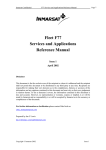
1
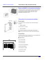
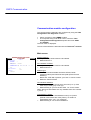
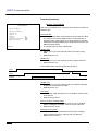
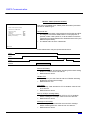
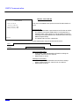
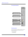
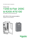
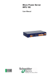
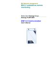
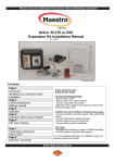
MV Network Management
Fault tracking
Monitoring and Control
Merlin Gerin Easergy Range
T200 P, T200 I
DNP3 Communication
User's manual
DNP3 Communication
Summary
General................................................................2
Functionnalities ....................................................2
Characteristics .....................................................2
Connection to the transmission line................3
Space available for a transmission interface .......3
Connection to a transmission interface................3
Communication moduleErreur! Signet non défini.
Location ...............................................................4
Communication module configuration .................5
Front panel indications.......................................11
Normal operation ...............................................11
Diagnostic using front panel indicators and
time-stamped events.........................................12
Replacing the Comms module...........................13
Device Profile Document ................................14
Implementation Table ......................................17
Point List...........................................................18
T200 P ...............................................................18
T200 I.................................................................21
Special considerations....................................32
Schneider Electric
T200 – DNP3 Communication – N0512-5GB
1
DNP3 Communication
General
Functionnalities
Telecontrol
Transmission of remote control commands to MV switches.
Transmission of the remote control command to reset fault
currents stored,
Transmission of enable/disable automatism command (when
automatism exists).
Monitoring
Position of switches,
Enable/disable automatism position (when automatism
exists),
Status of switches,
Phase and earth fault (A and B) currents of ways,
MV presence of ways ,
Digital inputs,
Local / Remote control operating mode,
Immediate AC supply OFF,
Delayed AC supply OFF,
Charger fault / FPI fault,
Battery fault,
Switchgear supply OFF,
Automatism operated (when automatism exists).
Measurements
Phase currents,
Voltage (T200 P)
Currents, voltages given by optional PowerMeters (T200 I).
Active and reactive energies given by optional PowerMeters
(further development) (T200 I).
Characteristics
Type of transmission
Protocol
Data format
Speed
Electrical interface
Type of connector
2
T200 – DNP3 Communication – N0512-5GB
asynchronous serial
DNP3
1 start bit, 8 data bits, no parity,
1 stop bit
200, 300, 600, 1200, 2400,
4800, 9600 bauds
RS232
9 pin SUB-D, male
Schneider Electric
Connection to the transmission line
DNP3 Communication
Space available for a transmission interface
The top right section of the equipment contains a space available
for a transmission interface (Modem, optical fibre, radio). A
support structure mounted on sliding rails offers multiple
possibilities for adding such a unit.
Connection to a transmission interface
Power supply
The interface may be connected to the "Telecomms supply"
terminals.
Voltage available :
12 VDC (10.8 to 14.8 VDC)
Current available :
See T200 documentation for further details. This output is
protected by a 4A time-lag fuse located on the right side of the
rack.
Serial I/O Port
The RS 232 serial I/O Port is available on the 9-pins SUB-D male
socket, located on the right side of the rack.
Signals wiring:
CD: Carrier Detect
T200
RD: Receive Data.
RS232
CD
DSR
RD
RTS
TD
CTS
DTR
RI
0V
TD: Transmit Data.
1
6
2
DTR: Data Terminal Ready.
7
3
8
DSR: Data Set Ready.
4
9
5
RTS: Request To Send.
CTS: Clear To Send.
RI: Ring Indicator.
Schneider Electric
T200 – DNP3 Communication – N0512-5GB
3
DNP3 Communication
Communication Module
Location
Communication using DNP3 protocol takes place via a "COMMS"
module.
The module is installed in the rack of a T200 enclosure on the left
side of the Power supply module.
4
T200 – DNP3 Communication – N0512-5GB
Schneider Electric
DNP3 Communication
Communication module configuration
The communication parameters are configured by using the T200
Configuration and diagnostic software.
Plug a computer to the COMMS module.
The computer being under DOS control, insert the T200
Configuration and diagnostic disquette and enter A:MG
then ENTER.
The main menu is displayed.
The use of the software is described into the T200 user’s manual.
Main screen
"
"
' '
)
*
*
)
)! +,)
! ! "
! ) )
"(
" / )
"
'
2
-)
*
--)
--)
) )
)
' #
.* +)
.*
*
*
#*
#*
-)
$
SCADA address:
• May take every value between 0 and 65534.
• Default value is 0.
"#
%#&
( "
'
(
! !
$
(
$
*
*
0*
1*
RTU address of ASDU:
• May take every value between 0 and 65534.
• Default value is 0.
*$ 3
)-
$ '
"#
-+ )
Modem type:
• The different links available are Direct RS 232, Radio
(external modem) and Direct RS 485 (with special Comms
interface).
Notice that, if RS 485 is present, you have no choice to enter.
• Default is "Direct RS 232"
CPU Modules installed:
• Permits to declare the CPUs which are used (1 to 4). Each
CPU may be used (yes) or not (no).
• Default setting is "yes" for the first CPU, "no" for the others.
Notice that some information are only available from CPU number
1 (Local, …).
PowerMeters installed:
• Permits declaration of PowerMeters used (1 to 6) when
optional Powermeters are used (T200 I). To declare a
PowerMeter enter "yes", "no" otherwise.
• Default setting is "no" for all PowerMeters.
Schneider Electric
T200 – DNP3 Communication – N0512-5GB
5
DNP3 Communication
Comms parameters
Modem : Direct RS 232
Comms Parameters
This menu is available when "Direct RS 232" has been chosen for
"Modem type".
Modem : Direct RS 232
Host baud rate : 1200 bauds
Handle DSR : no
Handle CD : no
Handle CTS
CTS delay
RTS (or CTS) to message delay
Message to RTS delay
ESCAPE=Exit
: no
: 20ms
: 20ms
: 20ms
Host baud rate:
• This is the transmission speed between the SCADA and RTU.
The range is from 200 to 9600 bauds. For test purposes, if
possible, select a low speed. So, it will be easier to show the
messages exchanged between the SCADA and the RTU (see
DNP3 analyser below).
• The default value is set to 1200 bauds.
Handle DSR:
• Select "yes" if you want T200 to detect connection, using
DSR.
• Default value is "no".
Handle CD:
• Select "yes" if you want T200 to control reception with CD.
• Default value is "no".
Frame transmission may be represented as below:
RTS
CTS
Frame
Handle CTS:
• Select "yes" if you want T200 to wait for CTS after asserting
RTS before sending the message.
• Default value is "no".
CTS Delay:
• It's the delay T200 will wait for CTS if handled. Value is from
20 to 500 ms.
• Default value is 20 ms.
RTS (or CTS) to message delay:
• It's the delay T200 will wait after RTS (or CTS if handled)
before sending the message. Value is from 0 to 500 ms.
• Default value is 20 ms.
Message to RTS delay:
• It's the delay T200 will wait after the end of the message
before asserting RTS low. Value is from 0 to 500 ms.
• Default value is 20 ms.
6
T200 – DNP3 Communication – N0512-5GB
Schneider Electric
DNP3 Communication
Modem : Radio (external modem)
Comms Parameters
This menu is available when "Radio (external modem)" has been
chosen for "Modem type".
Modem : Radio (external modem)
Host baud rate : 1200 bauds
DTR to RTS delay
Handle CTS
CTS delay
RTS (or CTS) to message delay
Message to RTS delay
: 20ms
: no
: 20ms
: 20ms
: 20ms
Host baud rate:
• This is the transmission speed between the SCADA and RTU.
The range is from 200 to 9600 bauds. For test purposes, if
possible, select a low speed. So, it will be easier to show the
messages exchanged between the SCADA and the RTU (see
DNP3 analyser below).
• The default value is set to 1200 bauds.
ESCAPE=Exit
Frame transmission may be represented as below:
DTR
RTS
CTS
Frame
DTR to RTS delay:
• It's the delay T200 will wait after asserting DTR before setting
RTS to "1" Value is from 0 to 500 ms.
• Default value is 20 ms.
Handle CTS:
• Select "yes" if you want T200 to wait for CTS after asserting
RTS before sending the message.
• Default value is "no".
CTS Delay:
• It's the delay T200 will wait for CTS if handled. Value is from
20 to 500 ms.
• Default value is 20 ms.
RTS (or CTS) to message delay:
• It's the delay T200 will wait after RTS (or CTS if handled)
before sending the message. Value is from 0 to 500 ms.
• Default value is 20 ms.
Message to RTS delay:
• It's the delay T200 will wait after the end of the message
before asserting RTS low. Value is from 0 to 500 ms.
• Default value is 20 ms.
Schneider Electric
T200 – DNP3 Communication – N0512-5GB
7
DNP3 Communication
Modem : Direct RS 485
Comms Parameters
Modem : Direct RS 485
Host baud rate : 1200 bauds
This menu is available when special Comms RS 485 interface is
used.
RTS to message delay : 20ms
Message to RTS delay : 20ms
ESCAPE=Exit
Host baud rate:
• This is the transmission speed between the SCADA and RTU.
The range is from 200 to 9600 bauds. For test purposes, if
possible, select a low speed. So, it will be easier to show the
messages exchanged between the SCADA and the RTU (see
DNP3 analyser below).
• The default value is set to 1200 bauds.
Frame transmission may be represented as below:
RTS
Frame
RTS to message delay:
• It's the delay T200 will wait after RTS before sending the
message. Value is from 0 to 500 ms.
• Default value is 20 ms.
Message to RTS delay:
• It's the delay T200 will wait after the end of the message
before asserting RTS low. Value is from 0 to 500 ms.
• Default value is 20 ms.
8
T200 – DNP3 Communication – N0512-5GB
Schneider Electric
DNP3 Communication
Profile
"
3
4
) 5! )
)
)- +
)6
)
! !
! )5
7
!
5
5
'
)
)
!
*+)
*#
*0
) )!
$
4
-) ) 6 )
9
*. !
+)
)5 )
7
)- + 8)
""
-)
)
)
)
* !
8 :)
! )
% - ) )
% - ) )
"
; <
)
8
8
7
/
=
)
; "( <
;" <
8
*+)
*+)
*.
*.
Inter-message delay:
• It's the minimum line idle interval between two consecutive
frames. Values are from 10 to 100 ms.
• 10 ms is the default value.
Requires Data Link Layer Confirmation:
• Select "yes" if you want User Data to be sent using a "SEND –
CONFIRM expected" frame type by the Link Layer. Selecting
"no" configures Link Layer to use a "SEND – NO REPLY
expected" frame type for User Data transmission.
Notice that in the case where "SEND – NO REPLY expected"
frame type is used T200 will never send "RESET of remote
link" frames. It will work strictly as a slave.
• Default is "yes".
Maximum Data Link Re-tries:
• Defines the number of re-tries by the Link Layer, when the
RTU doesn't receive any "CONFIRM" frame (ACK or NACK)
to a frame using a "SEND – CONFIRM expected" frame type.
When the Maximum Data Link Re-tries is reached without
confirmation, Link Layer will perform "RESET of remote link"
to re-initialise the link.
• Default value is 3.
Time-out:
• It's the delay Link Layer will wait for a "CONFIRM" frame after
sending a "SEND – CONFIRM expected" frame. Values are
from 1 to 10 s.
• Default value is 5 s.
Delay before emission:
• To avoid collision when spontaneously emitting on a halfduplex link, T200 will wait a T delay after seeing the link is no
more busy (using CD). If at this moment, CD is still not
present, T200 will send the message. If present, it will wait
another T delay. T delay is the sum of "Delay before
emission" and a random value. Configured values are from 0
to 10 s.
• Default value is 0 s.
Handle requested object(s) unknown bit :
• Because some SCADAs don't manage "requested object(s)
unknown" bit in "IIN" byte properly, you can permit or inhibit
it's transmission.
• Default value is "yes".
Schneider Electric
T200 – DNP3 Communication – N0512-5GB
9
DNP3 Communication
Transmission of measures on changes:
• You can permit or inhibit transmission of measures on
changes by selecting respectively "yes" or "no".
• Default value is "yes".
Measured value deadband (CPU):
• It's the difference, for measures obtained from CPU cards,
there must be between last reported value and current value
to have a Change Event generated. Range is from 1 to
10 000.
• Default value is 10
Measured value deadband (PM):
• It's the difference, for measures obtained from PowerMeters
(when option installed – T200 I only), there must be between
last reported value and current value to have a Change Event
generated. Range is from 1 to 10 000.
• Default value is 10
DNP3 analyser
DNP3 analyser
ESCAPE=Exit, SPACE=Pause, C=Clear
04:49.14
04:49.16
04:49.21
05:15.63
05:15.63
05:26.57
05:26.58
06:13.60
06:13.65
07:03.20
07:03.27
Pause…
10
Connected – answer mode
>> ……….
05 64 05 40 22 00 03 00 38 20
< ……….
05 64 05 80 03 00 22 00 4E E8
< ……….
05 64 05 C0 03 00 22 00 F4 D8
>> ……….
05 64 05 00 22 00 03 00 82 10
< ……….
05 64 08 C4 03 00 22 00 B9 36
C0 C0 17 C2 A7
>> ……….
05 64 10 44 22 00 03 00 68 2C
C0 C0 81 90 00 34 02 07 01 AF 00 38 3E
< ……….
05 64 12 C4 03 00 22 00 13 F2
C0 C1 02 32 01 07 01 20 D1 13 10 DB 00 8C CF
>> ……….
05 64 0A 44 22 00 03 00 C2 E8
C1 C1 81 80 00 5D 12
< ……….
05 64 0E C4 03 00 22 00 60 5D
C0 C2 01 3C 02 06 3C 01 06 FA 35
>> ……….
05 64 2A 44 22 00 03 00 40 19
C2 C2 81 80 00 01 01 00 60 65 33 01 01 00 80 9C B0 70
00 00 00 04 1E 02 00 E0 E3 01 00 00 01 00 00 00 AB 9E
00 80 00 00 80 9F 55
This analyser shows the different frames recognised with some
complementary information such as the direction of the frame
(Host -> T200 or T200 -> Host), possibly the error detected
(character framing error, overflow, checksum, bad length, bad
control character). In case of multiple errors, it's the first one that is
indicated.
Each correct frame is shown, one block per line (10 bytes for the
first one, 18 bytes for next ones, last one may be shorter).
T200 – DNP3 Communication – N0512-5GB
Schneider Electric
DNP3 Communication
Front panel indications
COMMS
Comms module is sending data
TD
RD
Comms module is receiving data
Comms module in fault
ON
Comms module powered
Plug for the connection of a PC used
for configuration and maintenance
Normal operation
During normal operation the COMMS module display is as follow :
RD and TD communication LEDs are lighted when T200 is
receiving or transmitting.
ON LED is lighted.
Fault LED is OFF.
Schneider Electric
T200 – DNP3 Communication – N0512-5GB
11
DNP3 Communication
Diagnostic using front panel indicators and
time-stamped events
T200 includes time stamped facilities in order to help in the
diagnostic. The events are saved into the CPU module.
The Time stamped events can be read locally from a lap top PC
computer equipped with the software ‘’T200 Configuration and
Diagnostic’’ and connected to the CPU configuration plug.
Connect the Lap top to the CPU module.
The PC being powered, and under Dos control, insert the
diskette ‘’T200 Configuration and Diagnostic’’ into the
driver and press A:MG then ENTER (Capital letter either not).
The main menu is displayed.
For information on the use of the configuration software package,
refer to the chapter entitled "Commissioning" in the T200 user's
manual.
Event
The "ON" LED on the
COMMS module is OFF.
The "Fault" LED on the
Comms module is ON.
The "Fault" LED on the
Comms module blink.
Possible cause
Equipment is not powered.
Power the equipment.
Control unit supply fuse is burnt.
Change the fuse on the Power supply
unit.
Fuse : 5x20mm, 0.8A semi time lag.
Change the Comms module.
Connect a lap top PC computer equipped
with the software "T200 Configuration
and Diagnostic" If "configuration lost" is
blinking in the main menu, verify or enter
correct configuration. After validation, if
problem persists change the Comms
module.
Press ‘’General RESET’’ button on the
Power supply unit. If the led doesn’t turn
OFF some seconds later, change the
Comms module.
Change the Comms module.
Comms module failure.
Configuration has been lost.
The Comms module software is in
fault.
The "Fault" LED on the
Comms module failure.
"Control" module is ON
and presence of MODBUS
comms failure event.
12
Solution
T200 – DNP3 Communication – N0512-5GB
Schneider Electric
DNP3 Communication
Replacing the Comms module
Removing the module
a) switch off the control unit,
Switch Off the AC supply.
Disconnect the batteries.
b) unscrew the two module locking screws and extract it from its
location.
Installing the module
a) install the new board and lock it to its slot,
b) switch the control unit on again.
IMPORTANT: Do not forget to configure the module; refer to
the section entitled " Communication module configuration "
Schneider Electric
T200 – DNP3 Communication – N0512-5GB
13
Device Profile Document
DNP3 Communication
DNP V3.00
DEVICE PROFILE DOCUMENT
Vendor Name :
SCHNEIDER ELECTRIC
Device Name :
T200 DNP3 V1.02
Highest DNP Level Supported :
For Requests :
L1
For Responses :
L1
Device Function :
Master
Slave
Notable objects, functions, and/or qualifiers supported in addition to the Highest DNP Levels
Supported (the complete list is described in the attached table) :
•
•
Binary input - All Variations : Read all points
Analog input - All Variations : Read all points
Maximum Data Link Frame Size (octets) :
Maximum Application Fragment Size (octets) :
(1)
Transmitted :
292
Transmitted :
1418
(if > 2048, must
be configurable)
Received :
(must be 292)
Received :
2048
(must be ≥ 249)
Maximum Data Link Re-tries :
Maximum Application Layer Re-tries :
None
Fixed at ____
(2)
Configurable, range 1 to 10
None
Configurable, range ____ to ____
(Fixed is not permitted)
(1)
Allows an application fragment to contain all class 0 data (including expansion, future use and reserved
points) and 100 event objects (corresponding to event buffer capacity).
(2)
Configuration with a PC.
14
T200 – DNP3 Communication – N0512-5GB
Schneider Electric
DNP3 Communication
Requires Data Link Layer Confirmation :
Never
Always
Sometimes
(3)
Configurable
Requires Application Layer Confirmation :
Never
Always (not recommended)
When reporting Event Data (Slave devices only)
When sending multi-fragment responses (Slave devices only)
Sometimes
If 'Sometimes', when ? _____________________________________
Configurable
If 'Configurable', how ? _____________________________________
Timeouts while waiting for :
Data Link Confirm
Complete Appl. Fragment
Application Confirm
Complete Appl. Response
None
None
None
None
Fixed at ____
Fixed at ____
Fixed at ____
Fixed at ____
Variable
Variable
Variable
Variable
(4)
Configurable
Configurable
Configurable
Configurable
Others _____________________________________________________________________
Sends/Executes Control Operations :
WRITE Binary Outputs
SELECT/OPERATE
DIRECT OPERATE
DIRECT OPERATE – NO ACK
Never
Never
Never
Never
Always
(5)
Always
(5)
Always
(5)
Always
Sometimes
Sometimes
Sometimes
Sometimes
Configurable
Configurable
Configurable
Configurable
Count > 1
Pulse On
Pulse Off
Latch On
Latch Off
Never
Never
Never
Never
Never
Always
(6)
Always
(6)
Always
(6)
Always
(6)
Always
(6)
Sometimes
Sometimes
Sometimes
Sometimes
Sometimes
Configurable
Configurable
Configurable
Configurable
Configurable
Queue
Clear Queue
Never
Never
Always
Always
Sometimes
Sometimes
Configurable
Configurable
(3)
Configuration with a PC.
Range 1 to 10 s, configuration with a PC.
(5)
Executes as it has been received.
(6)
Always execute a "Pulse On" with "on-time" = 3 s.
(4)
Schneider Electric
T200 – DNP3 Communication – N0512-5GB
15
DNP3 Communication
Reports Binary Input Change Events when no
specific variation requested :
Reports time-tagged Binary Input Change Events
when no specific variation requested :
Never
Binary Input Change With Time
Binary Input Change With Relative Time
Configurable (attach explanation)
Never
Only time-tagged
Only non-time-tagged
Configurable to send both, one or the
other (attach explanation)
Sends Unsolicited Responses :
Sends Static Data in Unsolicited Responses :
Never
Configurable (attach explanation)
Only certain objects
Sometimes (attach explanation)
Never
When Device Restarts
When Status Flags Change
No other options permitted.
ENABLE/DISABLE UNSOLICITED
Function codes supported
Default Counter Object/Variation :
Counters Roll Over at :
No Counters Reported
Configurable (attach explanation)
16 Bits
32 Bits
Other Value ___________
Point-by-point list attached
No Counters Reported
Configurable (attach explanation)
Default Object _______________
Default Variation______________
Point-by-point list attached
Sends Multi-Fragment Responses :
16
Yes
No
T200 – DNP3 Communication – N0512-5GB
Schneider Electric
Implementation Table
DNP3 Communication
OBJECT
REQUEST
RESPONSE
(slave must parse)
Description
Func
Codes
(dec)
Obj
Var
1
0
Binary Input – All Variations
1
1
Binary Input
129
00
1
2
Binary Input with Status
129
00
2
2
Binary Input Change with Time
129
17
10
0
Binary Output – All Variations
1
06
12
1
Control Relay Output Block
3,4,5,6
17,28
30
0
Analog Input – All Variations
1
06
30
2
32
1
Qual
Codes
(hex)
Notes
(master must parse)
Func
Codes
(dec)
Qual
Codes
(hex)
06
(7)
129
echo of
request
16-Bit Analog Input
129
00
2
16-Bit Analog Change Event without Time
129
17
40
0
Analog Output Status – All Variations
1
06
(7)
41
2
16-Bit Analog Output Block
3,4,5,6
17,28
(7)
50
1
Time and Date
2 (see
4.14)
07 where
quantity=1
52
2
Time Delay Fine
129
07
quantity=1
60
1
Class 0 Data
1
06
60
2
Class 1 Data
1
06,07,08
60
3
Class 2 Data
1
06,07,08
(7)
60
4
Class 3 Data
1
06,07,08
(7)
80
1
Internal Indications
2
00
index=7
No object
13
No object
23 (see
4.14)
Addition to Highest DNP Levels Supported
(7)
Response to this request is OBJECT UNKNOWN
Schneider Electric
T200 – DNP3 Communication – N0512-5GB
17
Point List
DNP3 Communication
Base
Expansion
T200 P
Description
Index
(hex/dec)
Control Relay
Output Block
Control Relay
Output Block
Control Relay
Output Block
Control Relay
Output Block
04 / 04
Default Static
Variation
Obj Var
Desc
12
1
05 / 05
12
1
Reserved
06 / 06
12
1
Reserved
07 / 07
12
1
Enable/Disable
Automatism
Control Relay
Output Block
15 / 21
12
1
FPI Reset
Control Relay
Output Block
18 / 24
12
1
Reserved
Description
Index
(hex/dec)
Binary Input
Binary Input
Binary Input
Binary Input
20 / 32
21 / 33
22 / 34
23 / 35
Binary Input
31 / 49
1
1, 2 No Status
2
2
1
With Time
FPI Reset
Binary Input
34 / 52
1
1, 2 No Status
2
2
1
With Time
Reserved
8
9
Default Event Variation
Obj
Var
Class
Point Name
Desc
SW1
Default Static
Default Event Variation
Variation
Obj Var
Desc
Obj Var Class
Desc
1
1, 2 No Status
2
2
1
With Time
1
1, 2 No Status
2
2
1
With Time
1
1, 2 No Status
2
2
1
With Time
1
1, 2 No Status
2
2
1
With Time
8
Point Name
SW1
Reserved
Reserved
Enable/Disable
Automatism
9
Only accepts "On" orders.
Always read as "Off".
18
T200 – DNP3 Communication – N0512-5GB
Schneider Electric
DNP3 Communication
Base
Expansion
Description
Index
(hex/dec)
Binary Input
Binary Input
Binary Input
Binary Input
Binary Input
Binary Input
Binary Input
Binary Input
Binary Input
Binary Input
Binary Input
Binary Input
Binary Input
Binary Input
Binary Input
Binary Input
Binary Input
Binary Input
Binary Input
Binary Input
Binary Input
Binary Input
Binary Input
Binary Input
3C / 60
3D / 61
3E / 62
3F / 63
40 / 64
41 / 65
42 / 66
43 / 67
44 / 68
45 / 69
46 / 70
47 / 71
48 / 72
49 / 73
4A / 74
4B / 75
4C / 76
4D / 77
4E / 78
4F / 79
50 / 80
51 / 81
52 / 82
53 / 83
Binary Input
Binary Input
Binary Input
Binary Input
54 / 84
55 / 85
56 / 86
57 / 87
1
1
1
1
1
1
1
1
No Status
No Status
No Status
No Status
2
2
2
2
2
2
2
2
1
1
1
1
With Time
With Time
With Time
With Time
Binary Input
58 / 88
1
1
No Status
2
2
1
With Time
Binary Input
Binary Input
Binary Input
59 / 89
5A / 90
5B / 91
1
1
1
1
1
1
No Status
No Status
No Status
2
2
2
2
2
2
1
1
1
With Time
With Time
With Time
Schneider Electric
Default Static
Default Event Variation
Variation
Obj Var
Desc
Obj Var Class
Desc
1
1
No Status
2
2
1
With Time
1
1
No Status
2
2
1
With Time
1
1
No Status
2
2
1
With Time
1
1
No Status
2
2
1
With Time
1
1
No Status
2
2
1
With Time
1
1
No Status
2
2
1
With Time
1
1
No Status
2
2
1
With Time
1
1
No Status
2
2
1
With Time
1
1
No Status
2
2
1
With Time
1
1
No Status
2
2
1
With Time
1
1
No Status
2
2
1
With Time
1
1
No Status
2
2
1
With Time
1
1
No Status
2
2
1
With Time
1
1
No Status
2
2
1
With Time
1
1
No Status
2
2
1
With Time
1
1
No Status
2
2
1
With Time
1
1
No Status
2
2
1
With Time
1
1
No Status
2
2
1
With Time
1
1
No Status
2
2
1
With Time
1
1
No Status
2
2
1
With Time
1
1
No Status
2
2
1
With Time
1
1
No Status
2
2
1
With Time
1
1
No Status
2
2
1
With Time
1
1
No Status
2
2
1
With Time
T200 – DNP3 Communication – N0512-5GB
Point Name
Phase fault SW
Earth fault A SW
Reserved
Reserved
Reserved
Reserved
Reserved
Reserved
Status SW
Reserved
Reserved
Reserved
Reserved
Reserved
Reserved
Reserved
Digital input 1
Digital input 2
Digital input 3
Reserved
Reserved
Reserved
Local
Immediate AC supply
OFF
Reserved
Charger / FPI fault
Battery fault
Switchgear supply
OFF
Delayed AC supply
OFF
Operated
Reserved
Reserved
19
DNP3 Communication
Base
Expansion
Description
Index
(hex/dec)
C0 / 192
Default Static
Variation
Obj Var
Desc
30
2
16-Bit
Analog Input
Obj
32
Var
2
Class
1
Analog Input
C1 / 193
30
2
16-Bit
32
2
1
Analog Input
C2 / 194
30
2
16-Bit
32
2
1
Analog Input
C3 / 195
30
2
16-Bit
32
2
1
20
Default Event Variation
T200 – DNP3 Communication – N0512-5GB
Desc
16-Bit
Without
Time
16-Bit
Without
Time
16-Bit
Without
Time
16-Bit
Without
Time
Point Name
Phase Current
Voltage Measure
Reserved
Reserved
Schneider Electric
DNP3 Communication
Base
Expansion
PowerMeter option
Description
04 / 04
Default Static
Variation
Obj Var
Desc
12
1
05 / 05
12
1
SW2
06 / 06
12
1
SW3
07 / 07
12
1
SW4
08 / 08
12
1
SW5
09 / 09
12
1
SW6
0A / 10
12
1
SW7
0B / 11
12
1
SW8
0C / 12
12
1
SW9
0D / 13
12
1
SW10
0E / 14
12
1
SW11
0F / 15
12
1
SW12
10 / 16
12
1
SW13
11 / 17
12
1
SW14
12 / 18
12
1
SW15
13 / 19
12
1
SW16
Control Relay
Output Block
15 / 21
12
1
FPI Reset
Control Relay
Output Block
Control Relay
Output Block
Control Relay
Output Block
Control Relay
Output Block
18 / 24
12
1
19 / 25
12
1
1A / 26
12
1
1B / 27
12
1
Enable/Disable
Automatism Group 1
Enable/Disable
Automatism Group 2
Enable/Disable
Automatism Group 3
Enable/Disable
Automatism Group 4
Control Relay
Output Block
Control Relay
Output Block
Control Relay
Output Block
Control Relay
Output Block
Control Relay
Output Block
Control Relay
Output Block
Control Relay
Output Block
Control Relay
Output Block
Control Relay
Output Block
Control Relay
Output Block
7Control Relay
Output Block
Control Relay
Output Block
Control Relay
Output Block
Control Relay
Output Block
Control Relay
Output Block
Control Relay
Output Block
10
Index
(hex/dec)
T200 I
Default Event Variation
Obj
Var
Class
Point Name
Desc
SW1
10
Only accepts "On" orders.
Schneider Electric
T200 – DNP3 Communication – N0512-5GB
21
DNP3 Communication
Base
Expansion
PowerMeter option
Description
Index
(hex/dec)
Binary Input
Binary Input
Binary Input
Binary Input
Binary Input
Binary Input
Binary Input
Binary Input
Binary Input
Binary Input
Binary Input
Binary Input
Binary Input
Binary Input
Binary Input
Binary Input
20 / 32
21 / 33
22 / 34
23 / 35
24 / 36
25 / 37
26 / 38
27 / 39
28 / 40
29 / 41
2A / 42
2B / 43
2C / 44
2D / 45
2E / 46
2F / 47
Binary Input
31 / 49
1
1, 2 No Status
2
2
1
With Time
FPI Reset
Binary Input
34 / 52
1
1, 2 No Status
2
2
1
With Time
Binary Input
35 / 53
1
1, 2 No Status
2
2
1
With Time
Binary Input
36 / 54
1
1, 2 No Status
2
2
1
With Time
Binary Input
37 / 55
1
1, 2 No Status
2
2
1
With Time
Enable/Disable
Automatism Group 1
Enable/Disable
Automatism Group 2
Enable/Disable
Automatism Group 3
Enable/Disable
Automatism Group 4
11
Default Static
Default Event Variation
Variation
Obj Var
Desc
Obj Var Class
Desc
1
1, 2 No Status
2
2
1
With Time
1
1, 2 No Status
2
2
1
With Time
1
1, 2 No Status
2
2
1
With Time
1
1, 2 No Status
2
2
1
With Time
1
1, 2 No Status
2
2
1
With Time
1
1, 2 No Status
2
2
1
With Time
1
1, 2 No Status
2
2
1
With Time
1
1, 2 No Status
2
2
1
With Time
1
1, 2 No Status
2
2
1
With Time
1
1, 2 No Status
2
2
1
With Time
1
1, 2 No Status
2
2
1
With Time
1
1, 2 No Status
2
2
1
With Time
1
1, 2 No Status
2
2
1
With Time
1
1, 2 No Status
2
2
1
With Time
1
1, 2 No Status
2
2
1
With Time
1
1, 2 No Status
2
2
1
With Time
Point Name
SW1
SW2
SW3
SW4
SW5
SW6
SW7
SW8
SW9
SW10
SW11
SW12
SW13
SW14
SW15
SW16
11
Always read as "Off"
22
T200 – DNP3 Communication – N0512-5GB
Schneider Electric
DNP3 Communication
Base
Expansion
PowerMeter option
Description
Index
(hex/dec)
Binary Input
Binary Input
Binary Input
Binary Input
Binary Input
Binary Input
Binary Input
Binary Input
Binary Input
Binary Input
Binary Input
Binary Input
Binary Input
Binary Input
Binary Input
Binary Input
Binary Input
Binary Input
Binary Input
Binary Input
Binary Input
Binary Input
Binary Input
Binary Input
3C / 60
3D / 61
3E / 62
3F / 63
40 / 64
41 / 65
42 / 66
43 / 67
44 / 68
45 / 69
46 / 70
47 / 71
48 / 72
49 / 73
4A / 74
4B / 75
4C / 76
4D / 77
4E / 78
4F / 79
50 / 80
51 / 81
52 / 82
53 / 83
Binary Input
Binary Input
Binary Input
Binary Input
54 / 84
55 / 85
56 / 86
57 / 87
1
1
1
1
1
1
1
1
No Status
No Status
No Status
No Status
2
2
2
2
2
2
2
2
1
1
1
1
With Time
With Time
With Time
With Time
Binary Input
58 / 88
1
1
No Status
2
2
1
With Time
Binary Input
Binary Input
Binary Input
59 / 89
5A / 90
5B / 91
1
1
1
1
1
1
No Status
No Status
No Status
2
2
2
2
2
2
1
1
1
With Time
With Time
With Time
Schneider Electric
Default Static
Default Event Variation
Variation
Obj Var
Desc
Obj Var Class
Desc
1
1
No Status
2
2
1
With Time
1
1
No Status
2
2
1
With Time
1
1
No Status
2
2
1
With Time
1
1
No Status
2
2
1
With Time
1
1
No Status
2
2
1
With Time
1
1
No Status
2
2
1
With Time
1
1
No Status
2
2
1
With Time
1
1
No Status
2
2
1
With Time
1
1
No Status
2
2
1
With Time
1
1
No Status
2
2
1
With Time
1
1
No Status
2
2
1
With Time
1
1
No Status
2
2
1
With Time
1
1
No Status
2
2
1
With Time
1
1
No Status
2
2
1
With Time
1
1
No Status
2
2
1
With Time
1
1
No Status
2
2
1
With Time
1
1
No Status
2
2
1
With Time
1
1
No Status
2
2
1
With Time
1
1
No Status
2
2
1
With Time
1
1
No Status
2
2
1
With Time
1
1
No Status
2
2
1
With Time
1
1
No Status
2
2
1
With Time
1
1
No Status
2
2
1
With Time
1
1
No Status
2
2
1
With Time
T200 – DNP3 Communication – N0512-5GB
Point Name
Phase fault SW1
Earth fault A SW1
Phase fault SW2
Earth fault A SW2
Phase fault SW3
Earth fault A SW3
Phase fault SW4
Earth fault A SW4
Status SW1
Status SW2
Status SW3
Status SW4
Earth fault B SW1
Earth fault B SW2
Earth fault B SW3
Earth fault B SW4
Digital Input 1
Digital Input 2
MV presence SW1
MV presence SW2
MV presence SW3
MV presence SW4
Local
Immediate AC supply
OFF
Digital Input 3
Charger / FPI fault
Battery fault
Switchgear supply
OFF
Delayed AC supply
OFF
Digital Input 4
Digital Input 5
Digital Input 6
23
DNP3 Communication
Base
Expansion
PowerMeter option
Description
Index
(hex/dec)
Binary Input
Binary Input
Binary Input
Binary Input
Binary Input
Binary Input
Binary Input
Binary Input
Binary Input
Binary Input
Binary Input
Binary Input
Binary Input
Binary Input
Binary Input
Binary Input
Binary Input
Binary Input
Binary Input
Binary Input
Binary Input
Binary Input
Binary Input
Binary Input
Binary Input
Binary Input
Binary Input
Binary Input
Binary Input
Binary Input
Binary Input
Binary Input
5C / 92
5D / 93
5E / 94
5F / 95
60 / 96
61 / 97
62 / 98
63 / 99
64 / 100
65 / 101
66 / 102
67 / 103
68 / 104
69 / 105
6A / 106
6B / 107
6C / 108
6D / 109
6E / 110
6F / 111
70 / 112
71 / 113
72 / 114
73 / 115
74 / 116
75 / 117
76 / 118
77 / 119
78 / 120
79 / 121
7A / 122
7B / 123
24
Default Static
Default Event Variation
Variation
Obj Var
Desc
Obj Var Class
Desc
1
1
No Status
2
2
1
With Time
1
1
No Status
2
2
1
With Time
1
1
No Status
2
2
1
With Time
1
1
No Status
2
2
1
With Time
1
1
No Status
2
2
1
With Time
1
1
No Status
2
2
1
With Time
1
1
No Status
2
2
1
With Time
1
1
No Status
2
2
1
With Time
1
1
No Status
2
2
1
With Time
1
1
No Status
2
2
1
With Time
1
1
No Status
2
2
1
With Time
1
1
No Status
2
2
1
With Time
1
1
No Status
2
2
1
With Time
1
1
No Status
2
2
1
With Time
1
1
No Status
2
2
1
With Time
1
1
No Status
2
2
1
With Time
1
1
No Status
2
2
1
With Time
1
1
No Status
2
2
1
With Time
1
1
No Status
2
2
1
With Time
1
1
No Status
2
2
1
With Time
1
1
No Status
2
2
1
With Time
1
1
No Status
2
2
1
With Time
1
1
No Status
2
2
1
With Time
1
1
No Status
2
2
1
With Time
1
1
No Status
2
2
1
With Time
1
1
No Status
2
2
1
With Time
1
1
No Status
2
2
1
With Time
1
1
No Status
2
2
1
With Time
1
1
No Status
2
2
1
With Time
1
1
No Status
2
2
1
With Time
1
1
No Status
2
2
1
With Time
1
1
No Status
2
2
1
With Time
T200 – DNP3 Communication – N0512-5GB
Point Name
Phase fault SW5
Earth fault A SW5
Phase fault SW6
Earth fault A SW6
Phase fault SW7
Earth fault A SW7
Phase fault SW8
Earth fault A SW8
Status SW5
Status SW6
Status SW7
Status SW8
Earth fault B SW5
Earth fault B SW6
Earth fault B SW7
Earth fault B SW8
Digital Input 7
Digital Input 8
MV presence SW5
MV presence SW6
MV presence SW7
MV presence SW8
Reserved
Reserved
Digital Input 9
Reserved
Reserved
Reserved
Reserved
Digital Input 10
Digital Input 11
Digital Input 12
Schneider Electric
DNP3 Communication
Base
Expansion
PowerMeter option
Description
Index
(hex/dec)
Binary Input
Binary Input
Binary Input
Binary Input
Binary Input
Binary Input
Binary Input
Binary Input
Binary Input
Binary Input
Binary Input
Binary Input
Binary Input
Binary Input
Binary Input
Binary Input
Binary Input
Binary Input
Binary Input
Binary Input
Binary Input
Binary Input
Binary Input
Binary Input
Binary Input
Binary Input
Binary Input
Binary Input
Binary Input
Binary Input
Binary Input
Binary Input
7C / 124
7D / 125
7E / 126
7F / 127
80 / 128
81 / 129
82 / 130
83 / 131
84 / 132
85 / 133
86 / 134
87 / 135
88 / 136
89 / 137
8A / 138
8B / 139
8C / 140
8D / 141
8E / 142
8F / 143
90 / 144
91 / 145
92 / 146
93 / 147
94 / 148
95 / 149
96 / 150
97 / 151
98 / 152
99 / 153
9A / 154
9B / 155
Schneider Electric
Default Static
Default Event Variation
Variation
Obj Var
Desc
Obj Var Class
Desc
1
1
No Status
2
2
1
With Time
1
1
No Status
2
2
1
With Time
1
1
No Status
2
2
1
With Time
1
1
No Status
2
2
1
With Time
1
1
No Status
2
2
1
With Time
1
1
No Status
2
2
1
With Time
1
1
No Status
2
2
1
With Time
1
1
No Status
2
2
1
With Time
1
1
No Status
2
2
1
With Time
1
1
No Status
2
2
1
With Time
1
1
No Status
2
2
1
With Time
1
1
No Status
2
2
1
With Time
1
1
No Status
2
2
1
With Time
1
1
No Status
2
2
1
With Time
1
1
No Status
2
2
1
With Time
1
1
No Status
2
2
1
With Time
1
1
No Status
2
2
1
With Time
1
1
No Status
2
2
1
With Time
1
1
No Status
2
2
1
With Time
1
1
No Status
2
2
1
With Time
1
1
No Status
2
2
1
With Time
1
1
No Status
2
2
1
With Time
1
1
No Status
2
2
1
With Time
1
1
No Status
2
2
1
With Time
1
1
No Status
2
2
1
With Time
1
1
No Status
2
2
1
With Time
1
1
No Status
2
2
1
With Time
1
1
No Status
2
2
1
With Time
1
1
No Status
2
2
1
With Time
1
1
No Status
2
2
1
With Time
1
1
No Status
2
2
1
With Time
1
1
No Status
2
2
1
With Time
T200 – DNP3 Communication – N0512-5GB
Point Name
Phase fault SW9
Earth fault A SW9
Phase fault SW10
Earth fault A SW10
Phase fault SW11
Earth fault A SW11
Phase fault SW12
Earth fault A SW12
Status SW9
Status SW10
Status SW11
Status SW12
Earth fault B SW9
Earth fault B SW10
Earth fault B SW11
Earth fault B SW12
Digital Input 13
Digital Input 14
MV presence SW9
MV presence SW10
MV presence SW11
MV presence SW12
Reserved
Reserved
Digital Input 15
Reserved
Reserved
Reserved
Reserved
Digital Input 16
Digital Input 17
Digital Input 18
25
DNP3 Communication
Base
Expansion
PowerMeter option
Description
Index
(hex/dec)
Binary Input
Binary Input
Binary Input
Binary Input
Binary Input
Binary Input
Binary Input
Binary Input
Binary Input
Binary Input
Binary Input
Binary Input
Binary Input
Binary Input
Binary Input
Binary Input
Binary Input
Binary Input
Binary Input
Binary Input
Binary Input
Binary Input
Binary Input
Binary Input
Binary Input
Binary Input
Binary Input
Binary Input
Binary Input
Binary Input
Binary Input
Binary Input
9C / 156
9D / 157
9E / 158
9F / 159
A0 / 160
A1 / 161
A2 / 162
A3 / 163
A4 / 164
A5 / 165
A6 / 166
A7 / 167
A8 / 168
A9 / 169
AA / 170
AB / 171
AC / 172
AD / 173
AE / 174
AF / 175
B0 / 176
B1 / 177
B2 / 178
B3 / 179
B4 / 180
B5 / 181
B6 / 182
B7 / 183
B8 / 184
B9 / 185
BA / 186
BB / 187
26
Default Static
Default Event Variation
Variation
Obj Var
Desc
Obj Var Class
Desc
1
1
No Status
2
2
1
With Time
1
1
No Status
2
2
1
With Time
1
1
No Status
2
2
1
With Time
1
1
No Status
2
2
1
With Time
1
1
No Status
2
2
1
With Time
1
1
No Status
2
2
1
With Time
1
1
No Status
2
2
1
With Time
1
1
No Status
2
2
1
With Time
1
1
No Status
2
2
1
With Time
1
1
No Status
2
2
1
With Time
1
1
No Status
2
2
1
With Time
1
1
No Status
2
2
1
With Time
1
1
No Status
2
2
1
With Time
1
1
No Status
2
2
1
With Time
1
1
No Status
2
2
1
With Time
1
1
No Status
2
2
1
With Time
1
1
No Status
2
2
1
With Time
1
1
No Status
2
2
1
With Time
1
1
No Status
2
2
1
With Time
1
1
No Status
2
2
1
With Time
1
1
No Status
2
2
1
With Time
1
1
No Status
2
2
1
With Time
1
1
No Status
2
2
1
With Time
1
1
No Status
2
2
1
With Time
1
1
No Status
2
2
1
With Time
1
1
No Status
2
2
1
With Time
1
1
No Status
2
2
1
With Time
1
1
No Status
2
2
1
With Time
1
1
No Status
2
2
1
With Time
1
1
No Status
2
2
1
With Time
1
1
No Status
2
2
1
With Time
1
1
No Status
2
2
1
With Time
T200 – DNP3 Communication – N0512-5GB
Point Name
Phase fault SW13
Earth fault A SW14
Phase fault SW15
Earth fault A SW16
Phase fault SW13
Earth fault A SW14
Phase fault SW15
Earth fault A SW16
Status SW13
Status SW14
Status SW15
Status SW16
Earth fault B SW13
Earth fault B SW14
Earth fault B SW15
Earth fault B SW16
Digital Input 19
Digital Input 20
MV presence SW13
MV presence SW14
MV presence SW15
MV presence SW16
Reserved
Reserved
Digital Input 21
Reserved
Reserved
Reserved
Reserved
Digital Input 22
Digital Input 23
Digital Input 24
Schneider Electric
DNP3 Communication
Base
Expansion
PowerMeter option
Description
Index
(hex/dec)
C0 / 192
Default Static
Variation
Obj Var
Desc
30
2
16-Bit
Analog Input
Obj
32
Var
2
Class
1
Analog Input
C1 / 193
30
2
16-Bit
32
2
1
Analog Input
C2 / 194
30
2
16-Bit
32
2
1
Analog Input
C3 / 195
30
2
16-Bit
32
2
1
Analog Input
C4 / 196
30
2
16-Bit
32
2
1
Analog Input
C5 / 197
30
2
16-Bit
32
2
1
Analog Input
C6 / 198
30
2
16-Bit
32
2
1
Analog Input
C7 / 199
30
2
16-Bit
32
2
1
Analog Input
C8 / 200
30
2
16-Bit
32
2
1
Analog Input
C9 / 201
30
2
16-Bit
32
2
1
Analog Input
CA / 202
30
2
16-Bit
32
2
1
Analog Input
CB / 203
30
2
16-Bit
32
2
1
Analog Input
CC / 204
30
2
16-Bit
32
2
1
Analog Input
CD / 205
30
2
16-Bit
32
2
1
Analog Input
CE / 206
30
2
16-Bit
32
2
1
Analog Input
CF / 207
30
2
16-Bit
32
2
1
Schneider Electric
Default Event Variation
T200 – DNP3 Communication – N0512-5GB
Desc
16-Bit
Without
Time
16-Bit
Without
Time
16-Bit
Without
Time
16-Bit
Without
Time
16-Bit
Without
Time
16-Bit
Without
Time
16-Bit
Without
Time
16-Bit
Without
Time
16-Bit
Without
Time
16-Bit
Without
Time
16-Bit
Without
Time
16-Bit
Without
Time
16-Bit
Without
Time
16-Bit
Without
Time
16-Bit
Without
Time
16-Bit
Without
Time
Point Name
SW1 Current
SW2 Current
SW3 Current
SW4 Current
SW5 Current
SW6 Current
SW7 Current
SW8 Current
SW9 Current
SW10 Current
SW11 Current
SW12 Current
SW13 Current
SW14 Current
SW15 Current
SW16 Current
27
DNP3 Communication
Base
Expansion
PowerMeter option
Description
Index
(hex/dec)
D0 / 208
Default Static
Variation
Obj Var
Desc
30
2
16-Bit
Analog Input
Obj
32
Var
2
Class
1
Analog Input
D1 / 209
30
2
16-Bit
32
2
1
Analog Input
D2 / 210
30
2
16-Bit
32
2
1
Analog Input
D3 / 211
30
2
16-Bit
32
2
1
Analog Input
D4 / 212
30
2
16-Bit
32
2
1
Analog Input
D5 / 213
30
2
16-Bit
32
2
1
Analog Input
D6 / 214
30
2
16-Bit
32
2
1
Analog Input
D7 / 215
30
2
16-Bit
32
2
1
Analog Input
D8 / 216
30
2
16-Bit
32
2
1
Analog Input
D9 / 217
30
2
16-Bit
32
2
1
Analog Input
DA / 218
30
2
16-Bit
32
2
1
Analog Input
DB / 219
30
2
16-Bit
32
2
1
28
Default Event Variation
T200 – DNP3 Communication – N0512-5GB
Desc
16-Bit
Without
Time
16-Bit
Without
Time
16-Bit
Without
Time
16-Bit
Without
Time
16-Bit
Without
Time
16-Bit
Without
Time
16-Bit
Without
Time
16-Bit
Without
Time
16-Bit
Without
Time
16-Bit
Without
Time
16-Bit
Without
Time
16-Bit
Without
Time
Point Name
PM 1 Current 1
PM 1 Current 2
PM 1 Current 3
PM 1 Voltage 1
PM 1 Voltage 2
PM 1 Voltage 3
PM 2 Current 1
PM 2 Current 2
PM 2 Current 3
PM 2 Voltage 1
PM 2 Voltage 2
PM 2 Voltage 3
Schneider Electric
DNP3 Communication
Base
Expansion
PowerMeter option
Description
Index
(hex/dec)
DC / 220
Default Static
Variation
Obj Var
Desc
30
2
16-Bit
Analog Input
Obj
32
Var
2
Class
1
Analog Input
DD / 221
30
2
16-Bit
32
2
1
Analog Input
DE / 222
30
2
16-Bit
32
2
1
Analog Input
DF / 223
30
2
16-Bit
32
2
1
Analog Input
E0 / 224
30
2
16-Bit
32
2
1
Analog Input
E1 / 225
30
2
16-Bit
32
2
1
Analog Input
E2 / 226
30
2
16-Bit
32
2
1
Analog Input
E3 / 227
30
2
16-Bit
32
2
1
Analog Input
E4 / 228
30
2
16-Bit
32
2
1
Analog Input
E5 / 229
30
2
16-Bit
32
2
1
Analog Input
E6 / 230
30
2
16-Bit
32
2
1
Analog Input
E7 / 231
30
2
16-Bit
32
2
1
Schneider Electric
Default Event Variation
T200 – DNP3 Communication – N0512-5GB
Desc
16-Bit
Without
Time
16-Bit
Without
Time
16-Bit
Without
Time
16-Bit
Without
Time
16-Bit
Without
Time
16-Bit
Without
Time
16-Bit
Without
Time
16-Bit
Without
Time
16-Bit
Without
Time
16-Bit
Without
Time
16-Bit
Without
Time
16-Bit
Without
Time
Point Name
PM 3 Current 1
PM 3 Current 2
PM 3 Current 3
PM 3 Voltage 1
PM 3 Voltage 2
PM 3 Voltage 3
PM 4 Current 1
PM 4 Current 2
PM 4 Current 3
PM 4 Voltage 1
PM 4 Voltage 2
PM 4 Voltage 3
29
DNP3 Communication
Base
Expansion
PowerMeter option
Description
Index
(hex/dec)
E8 / 232
Default Static
Variation
Obj Var
Desc
30
2
16-Bit
Analog Input
Obj
32
Var
2
Class
1
Analog Input
E9 / 233
30
2
16-Bit
32
2
1
Analog Input
EA / 234
30
2
16-Bit
32
2
1
Analog Input
EB / 235
30
2
16-Bit
32
2
1
Analog Input
EC / 236
30
2
16-Bit
32
2
1
Analog Input
ED / 237
30
2
16-Bit
32
2
1
Analog Input
EE / 238
30
2
16-Bit
32
2
1
Analog Input
EF / 239
30
2
16-Bit
32
2
1
Analog Input
F0 / 240
30
2
16-Bit
32
2
1
Analog Input
F1 / 241
30
2
16-Bit
32
2
1
Analog Input
F2 / 242
30
2
16-Bit
32
2
1
Analog Input
F3 / 243
30
2
16-Bit
32
2
1
30
Default Event Variation
T200 – DNP3 Communication – N0512-5GB
Desc
16-Bit
Without
Time
16-Bit
Without
Time
16-Bit
Without
Time
16-Bit
Without
Time
16-Bit
Without
Time
16-Bit
Without
Time
16-Bit
Without
Time
16-Bit
Without
Time
16-Bit
Without
Time
16-Bit
Without
Time
16-Bit
Without
Time
16-Bit
Without
Time
Point Name
PM 5 Current 1
PM 5 Current 2
PM 5 Current 3
PM 5 Voltage 1
PM 5 Voltage 2
PM 5 Voltage 3
PM 6 Current 1
PM 6 Current 2
PM 6 Current 3
PM 6 Voltage 1
PM 6 Voltage 2
PM 6 Voltage 3
Schneider Electric
DNP3 Communication
Base
Expansion
PowerMeter option (further
development)
Description
Not defined
Index
(hex/dec)
Default Static
Variation
Obj Var
Desc
Default Event Variation
Obj
Var
Class
Point Name
Desc
F4 / 244
PM 1 Active energy
F5 / 245
PM 1 Reactive energy
F6 / 246
PM 2 Active energy
F7 / 247
PM 2 Reactive energy
F8 / 248
PM 3 Active energy
F9 / 249
PM 3 Reactive energy
FA / 250
PM 4 Active energy
FB / 251
PM 4 Reactive energy
FC / 252
PM 5 Active energy
FD / 253
PM 5 Reactive energy
FE / 254
PM 6 Active energy
FF / 255
PM 6 Reactive energy
(further development)
Not defined
(further development)
Not defined
(further development)
Not defined
(further development)
Not defined
(further development)
Not defined
(further development)
Not defined
(further development)
Not defined
(further development)
Not defined
(further development)
Not defined
(further development)
Not defined
(further development)
Not defined
(further development)
Schneider Electric
T200 – DNP3 Communication – N0512-5GB
31
DNP3 Communication
Special considerations
Internal INdications
Time-synchronization required from the master
Bit 4 of first IIN byte is set when T200 starts up.
More, T200 needs to be synchronized by the master every
hour. This is necessary to assume a good accuracy of timestamps. So, if T200 doesn't receive any synchronisation from
the master in an hour delay (since the last synchronisation
message received), the IIN bit is set.
32
T200 – DNP3 Communication – N0512-5GB
Schneider Electric
Schneider Electric SA
N0512-5GB Issue: 02/2004
Schneider Electric
64-70, avenue Jean-Baptiste
Clément
F- 92646 Boulogne Billancourt
Cedex
Tel.: +33 (0)1 46 99 70 00
Fax: +33 (0)1 46 99 71 00
http://www.schneider-electric.fr
Due to changes in standards and equipment,
the characteristics mentioned in the texts and images of this
document cannot be considered as binding unless confirmed
by our services.
Publication: Schneider Electric Industries SA
T200 – DNP3 Communication – N0512-5GB
33