1
MV Electrical network management
Easergy range
Flair 200C & T200
MV substation control and monitoring units
Modbus master communication
Easergy T200/F200C
Summary
1
OVERVIEW .................................................................................................................................................. 3
2
GENERAL PRINCIPLES ............................................................................................................................. 3
3
CONFIGURATION ....................................................................................................................................... 4
3.1 MODBUS MASTER COMMUNICATION CONFIGURATION PAGE ............................................................................... 4
3.2 SLAVES CONFIGURATION PAGE ....................................................................................................................... 6
3.3 VARIABLE CONFIGURATION PAGE .................................................................................................................... 7
4
CONNECTION OF THE RS232/RS485 TRANSMISSION LINK ................................................................. 9
4.1 RS485 OR RS422 CONNECTION .................................................................................................................... 9
4.2 RS232 CONNECTION ..................................................................................................................................... 9
2
NT00121-EN-07
Easergy T200/F200C
Modbus master communication
1 Overview
The T200 and the Flair 200C allow the connection of T200 to external equipments
by using MODBUS protocol. It includes an additional serial port (RS232 or
RS485) and a configuration table, allowing to connect different devices
(SEPAM, Power meter, PLC…).
The Flair 200C and the T200 are able to reach external equipments using the
Modbus protocol (via a RS232/RS485 modem) but also using the Modbus TCP
protocol (on the Ethernet port). It is necessary to have a unit including an Ethernet
port (Ethernet port is an option for Flair 200C).
2 General principles
The user has to configure the link (for Modbus) or ethernet link (for Modbus TCP):
baud rate, parity, stop bits, polarization, timeout, etc…
Supervisor
IEC, Modbus, DNP3…
The T200 and the Flair 200C can access different types of variables that can be
associated to external devices :
•
Digital input (DI)
•
Digital output (DO)
•
Analog input (AI)
•
Analog output (AO)
•
Double digital input ((DDI) (*)
•
Double digital output (DDO) (*)
(*) Note: these types of variables are actually only available on the Flair 200C.
They will be also available soon on the T200.
T200 Master
Modbus Master
The following variables can also be defined to control switchgears managed by
slaves T200 on Modbus Master network :
Double Command (TCD) (°)
Double Information (TSD) (°)
The unit that is the master manages the associated signals (e.g. CR code) that
correspond to the commands on switchgear sent to the T200 slave.
T200 Slaves
(°) Note: these types of variables are actually onl y available on the T200. They
will be also available soon on the Flair 200C.
Each variable has its own parameters: Modbus slave address, word(s) to read, bit
(for bit access), Modbus function to use.
In order to organize the communication between T200 and slaves, some
variables can be grouped together in a topic, which allows to control simply a
group of variables (Modbus slave address, refresh period).
NT00121-EN-07
3
Easergy T200/F200C
Modbus master communication
3 Configuration
3.1 Modbus master communication
configuration page
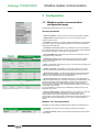
Global Modbus parameters can be set in this menu.
General parameters
Serial line interface : Allows to choose the interface type: RS232 or RS485.
Reply timeout : Modbus reply time out. Can be set according to slaves
maximum response time.
Polarization : (RS485 only). Allows to polarize the RS485 link to the T200/Flair
200C side. In theory, the line should be polarized to one end of the RS485 line,
preferably to the Master side.
Resistance to end of line (RS485 only). Enables the end of line resistance to
the T200/Flair 200C side. In theory, the end of line resistance must be enabled at
both ends of the RS485 line, especially for long-length lines.
Line type (RS485 only). Sets the line type for the use of RS485 link. Can be
configured with two or four wires.
Transmission speed : T200 and Flair 200C supports transmission speed
between 200bds and 38400 bds. Choose a speed according to the Modbus
slaves you are using.
Parity : Configuration of the parity to be used . Choose a parity according to the
Modbus slaves you are using.
Number of stop bits : Configuration of the number of stop bits to be used.
Choose a number of stop bits according to the Modbus slaves you are using.
Maximum frame length : In Modbus, allows definition of the maximum frame
length. Recommended value 255, to be modified and reduced only if a radio
medium is used, where there can be major interference.
Event polling period : When a Modbus slave has an event table (Sepam or
T200 slave type for example), it is possible to retrieve this event table every x sec.
Retrieval of the slaves event tables makes it possible, among other things, to
improve the time stamping of variables (time stamping locally in the slave).
For this purpose the address of the event table must be defined (refer to "Slaves
configuration page" chapter).
For more information concerning event management, please refer to the User
Manual for the pro tocol.
Event on validity change: in DNP3 and IEC101/104 protocol only, events can
be generated for all variables associated with a slave if the state of the
communication with the slave changes (loss of communication, return of
communication). The events are then generated with the last known status, but a
status invalid / valid is indicated (bits "NT + IV" in IEC 101/104 bit "Offline" in
DNP3).
Modbus TCP client parameters
Parameters to be entered if the Modbus slave is declared on the Ethernet port
Server port: TCP port of the server (Sepam on Ethernet for example)
Connection timeout: period of communication inactivity with the slave before
disconnection.
4
NT00121-EN-07
Easergy T200/F200C
Modbus master communication
Topics
A topic is a group of variables not necessarily belonging to the same slave device
and which can be updated by cyclic polling of the corresponding devices at
adjustable time intervals. Up to 5 topics can be created. For each topic you can
define :
Slave address : Modbus slave address that will be used for any variable
attached to this topic if such address is not defined in the variable definition
screen.
Watch period : from 0 to 100 000 ms. Period for reading the variables attached
to the topic. If set to 0 ms, the topic variables will be polled as quickly as possible
by the T200 or the Flair 200C.
Topic on : If disabled, variables attached to this topic will not be scanned any
more.
Modbus Master Communication information:
Information concerning communication with the Modbus slaves is accessible for
the supervisor from the protocol table of the T200 or Flair 200C device.
Slaves state table address: Information and commands made available
by a control station regarding the state of communication between the
T200/Flair 200C and the slave. Word address at the beginning of a read zone
containing 255 words, one for each possible slave address. Default: 1280.
Bit 1 : At least one variable is configured for this PLC
Bit 2 : Faulty PLC
Bit 3 : Communication in progress or established
Example: If the value 1280 is configured as an address : bit 1 of word 1281
means that at least one variable is configured on slave PLC 1. The address
1280 provides information on all the PLCs.
An address configured as 0 deactivates the function:
Slaves Command table address : Word address at the beginning of a
read/write zone containing 255 bits, one bit for each possible slave address.
Control bit status :
0 Inhibition of all communication with the slave
1 Authorization of communication with the slave
Example : If the value 1536 is configured as an address, the bit 0 of word
1537 writted with 0 value, inactivate the communication of the slave 16.
Communication error variable : A specific variable (TSL65) is
automatically added to the default setting of T200/F200C, when the function
Modbus Master is included in the unit.
This variable goes to ON status when one slave occurs a communication
error on the Modbus Master link.
Diagnosis
Number of frames sent, received, errors (CRC, time out), exceptions type 1, 2, 3
or 4, number of analog and digital variables configured.
Exception 01 : The requested function is not recognised by the slave
Exception 02 : The bit and word addresses indicated when the request was
made do not exist in the slave
Exception 03 : The bit and word values indicated when the request was made
are not allowed in the slave.
Exception 04 : The slave has started to execute the request, but cannot continue
to process it completely.
NT00121-EN-07
5
Easergy T200/F200C
Modbus master communication
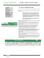
3.2 Slaves configuration page
To create a new slave, click on the "Add" button in the top right-hand of the page.
Slave / Active : If OFF, all variables on this slave will not be scanned any more.
Slave / Type :
o
SEPAM, or T200: With this choice for the type of slave the T200
will automatically use the right format of predefined frame for
calling and synchronize the slave. These Modbus slaves support
time-stamped events. If the variables defined for this slave has
been configured with "Event" as Topic type (refer to "Variable
configuration page" chapter), the events will first be generated and
time-stamped at source by the slave before being read as events
time-stamped by the T200/Flair 200C.
o
Modbus: any Modbus device on which the digital or analog data
will be read or written by the T200/Flair 200C and then timestamped by the T200/Flair 200C.
Events / Address : Address of the event table on the slave device. Meaningless
for slave type “Modbus” or "Other".
CR code: Address for the code which corresponds to the result of the control
that has been sent to the slave. It is only used for a slave (T200 type) which is
able to manage remote double command (TCD) that generally correspond to
switchgear control.
Time format: Format of the date and time information of the events (2 or 4
words). 4 words for SEPAM or T200, according to W320E configuration for
W320E. Note that 2 words format does not include ms (resolution 1s).
Meaningless for slave type “Modbus” or "Other". Refer to the Modbus protocol
documentation of the T200/Flair 200C for the 2- or 4-word format.
Time synchronisation / Address and period: Address of the time
synchronisation zone of the slave allowing T200/Flair 200C to set date and time in
the slave. Period of the time synchronisation (how often T200/Flair 200C will set
the slave date and time). Meaningless for slave type “Modbus” or "Other".
Note: The speed of event reading is defined in the Modbus Master Port
Parameters page
IP address: IP address of the slave PLC if defined on the Ethernet port.
Note: If the address is different from 0.0.0.0, the T200/Flair 200C tries to access
the slave via the Ethernet port
Unit ID: Used only when slave is defined on the Ethernet port. This field is used
in the Modbus TCP frame sent by the Flair 200C for intra-system routing. Set to
255 (0xFF) by default in the Modbus protocol, this Unit ID can be changed so that
to forward the message downstream to another slave via a Modbus TCP->
Modbus RTU gateway.
6
NT00121-EN-07
Easergy T200/F200C
Modbus master communication
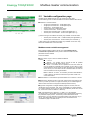
3.3 Variable configuration page
Variables can be added from this menu by clicking the button "Add".
Use the following screen to define variables to be read on Modbus slave devices:
Variables on T200 and F200C :
o
o
o
o
o
o
o
"Single point information DI" : to add digital inputs
"Single point command DO" : to add digital outputs
"Measure AI" : to add analog inputs
"Analog output AO" to add analog outputs
"Internal counter CNT" : to add a counter
"Double point information DDI" : to add a 2-bit digital input (*)
"Double point command DD0" : to add a 2-bit digital output (*).
(*) Note: these types of variables are actually only available on the Flair 200C.
o
o
"Double point information TSD" : to add a double point signalization (°)
"Double point command TCD" : to add a double point command (°).
(°) Note: these types of variables are actually onl y available on the T200. They
will be also available soon on the Flair 200C.
Modbus master variable management
Each variable created includes a specific zone called "Modbus Master
Communication parameters" which permit to define the Modbus access
parameters of these variable.
This zone includes:
Topic number: Topic to which to variable is attached.
Choose :
"1 to 5" or
“Without” : the variable will be scanned as fast as possible
(equivalent to a topic with watch period = 0) or
“Event”: The variable will be updated from the slave event list.
Only for variable of a SEPAM, T200 or W320E. In such case, it is even
recommended to use this mode for better performance for all variables
which can be put in the slave event list: T200/Flair 200C will scan the
event list rather that scanning all variables.
Note : If “Without” or “Event”, it is necessary to enter a slave address. If
a topic number is not entered, it will use the topic slave number if no
one is entered here.
Slave address: To overwrite the topic slave address or for “Without” or “Event”.
Read function: Modbus function to be used. Check that the slave supports the
function you select (for instance, it might be necessary to use a Read register to
read a bit if the slave does not support the Read input status function)
Type: Not configurable on a digital variable ("single bit" for the DI, DO and
"Double bits" for the DDI, DDO, TCD, TSD) / configurable on an analog variable.
For a analog variable, various types of words can be defined (16 bits word, 32 bits
H/L, 32 bits L/H or N bits or Real H/L or Real L/H).
Note: If the selected type is "Real H / L" or "Real L / H", the parameter
"Correction factor" in the variable configuration page is automatically replaced by
the parameter "Display format". The accuracy of the measurement can be
adjusted from 1 to 0.001 and also to a scientific notation (with exponents, eg 2 x
10e-3). This setting affects only the display format of the measure in the
"Visualization" page of the Web server.
NT00121-EN-07
7
Easergy T200/F200C
Modbus master communication
Word: word address of the analog information or address of the word
containing the bit for digital information. Up to 0xFFF=4095.
This is to be entered in decimal.
Bit (for digital or analogue information type N bits only): bit number of the bit to
read or write in the word.
Lenght : (for analogue information type N bits only) : bit number of the bit to
read from the first bit defined in the "Bit" field.
Note: To calculate a decimal value in the form (word, bit), proceed as follows:
Calculation of a word bit from a decimal address:
• Word address = decimal address modulo 16 (integer value)
• Bit address = decimal part * 16
Example: address 255 255 / 16 = 15.9375 (Word = 15)
0.9375 * 16 = 15 (Bit = 15)
Write function (for output information only): Function to be used for writing the
variable.
Read only (for output information only): If checked, the control commands will
not appear any more in the configuration software “control” screen, therefore not
allowing any more to write the variable locally (but in any case can be controlled
from SCADA).
The other variable parameters are described in the user manual of the T200 and
Flair 200C.
The TCD variables needs to be configured with a specific parameter in the
common zone "General parameters" :
Logical adress of associated input : To work properly, a TCD must be
associated to a TSD. A TCD created will be configured on the Master
T200/F200C to be associated to the corresponding TSD defined in the slave.
(see image opposite).
Exemple of associated input TCD-TSD
Modbus Master traces page :
The maintenance pages include an additional trace for Modbus master (provided
that the Java Runtime Environment software has been installed), which allows to
view communication exchanges between the T200/Flair 200C and the Modbus
slaves.
This trace is displayed on screen in decoded form to make reading of the frame’s
content easier :
o
Column 1 : time-and-date stamping of the frame (in
hour:minutes:seconds: thousandth of second format)
o
Column 2 : direction of dialogue T200/Flair 200C PC or PC T200/Flair 200C with associated address of the slave
o
Column 3 : hexadecimal frame + brief description of the content of the
frame.
Note: if the Modbus master communication is performed on the RS232/RS485 or
on the Ethernet port, in both cases, the trace is displayed in the "Trace Modbus
Master Port' page.
8
NT00121-EN-07
Easergy T200/F200C
Modbus master communication
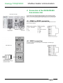
4 Connection of the RS232/RS485
transmission link
Flair 200C CPU card
The connection of the RS232/RS485 transmission link to the slaves is made
directly on the RJ45 connector of Modbus Master port on T200 COM card front
panel or in front of the RS232/RS485 modem inside the box for the Flair 200C.
4.1 RS485 or RS422 connection
Connect the RS485 or RS422 line in accordance with the diagram of the RJ45
type connector opposite.
4.2 RS232 connection
Connect the RS232 line in accordance with the diagram of the RJ45 type
connector opposite.
T200 COM card
NT00121-EN-07
9
Easergy T200/F200C
10
Personal notes
NT00121-EN-07
Easergy T200/F200C
NT00121-EN-07
Personal notes
11
Schneider Electric Industries SAS
As standards, specifications and designs change from time to time,
please ask for confirmation of the information given in this publication.
Schneider Electric Telecontrol
839 chemin des Batterses
Z.I. Ouest
01700 St Maurice de Beynost
Tel : +33 (0)4 78 55 13 13
Fax : +33 (0)4 78 55 50 00
http://www.schneider-electric.com
E-mail : [email protected]
NT00121-EN-07
01/2013
Publication, production and printing : Schneider Electric Telecontrol
Made in France - Europe