1
®
M
I
D
I
F
l
y
®
Congratulations and Thank You
®
For Purchasing the MIDIFly
Precautions
Precautions:
Since the introduction of Parker guitars in 1993 we have received an overwhelming amount of positive comments from players and reviewers alike,
such as; "It's everything a guitar should be," "Light and vibrant," "Alive, totally
responsive to the touch," and "A pure tone engine." Along with the praise has
been one common request, "When will Parker make a MIDI guitar?"
• Avoid getting the MIDIFly wet and don't use it near water. If you do you
run the risk of damaging the MIDIFly and possible electrical shock.
That time is now!
The new MIDIFly guitar features Parker's versatile magnetic and piezo pickup
design along with Virtual DSP's MidiAxe™ guitar-to-MIDI converter system.
Utilizing the Fishman® piezo circuit to trigger the internal MIDIFly DSP, the
results are a fast tracking and amazingly stable "glitch friendly" MIDI guitar
controller.
The MIDIFly is also extremely easy-to-use due to the lack of complex MIDI
user controls. Using a simple yet functional design, the guitarist can intuitively control the essential functions of MIDI, along with the magnetic and piezo
pickups, from the normal array of controls he is already accustomed to in one
single instrument.
MIDI IN and OUT ports are provided that allow standard connection to any
MIDI device from synthesizers to computers. This is a big improvement over
current MIDI guitar systems that require a clumsy 13-pin connector and external converter box as well as additional pickups added to the guitar.
Improved tracking and stability, simple to operate controls, plug-and-play
operation, software updateable design; a MIDI guitar that finally makes musical sense!
Features
and
Controls
Features
and
Controls
•
•
•
•
•
•
•
•
•
•
•
•
•
•
•
•
•
•
•
•
•
Solid hardwood body
One piece solid wood neck encapsulated in glass and carbon fibers
Composite finger board
Hardened stainless steel frets
Easy-Access truss rod adjustor
Sperzel® locking tuning machines
Custom DiMarzio® magnetic pickups
FISHMAN® Active Piezo pickup system
Built-in MidiAxe™ digital guitar-to-MIDI converter system
Cast aluminum bridge with stainless steel bridge saddles
3/16" stainless steel vibrato bar
Stereo output jack featuring "Smart Switching"
MIDI IN/OUT connectors
Magnetic Pickup Volume Control
Five-Position Magnetic Pickup Selector
Magnetic Pickup Tone Control
Pickup Selector, (Magnetic/Both/Piezo)
Piezo Volume Control
MIDI/Synth Volume Control
MIDI Mode Switch
MIDI Octave (Transpose) Switch
• Please read all of the instructions in this owner's manual.
• Unplug the AC adapter from the power outlet if the unit is not going to be
used for a long period of time.
• If the MIDIFly fails to operate properly, do not attempt your own repair.
Please contact your dealer or our technical support group for information
on the nearest authorized service location.
NOTE: During normal operation the electronics compartment on the back of the
MIDIFly body will be warm to the touch. This is normal and is not an indication of a
problem.
WARNING: The use of an AC adapter other than the one supplied with the
MIDIFly may cause overheating and/or damage to the MIDIFly .
NOTE: This equipment has been tested and found to comply with the limits for a Class
B digital device, pursuant to Part 15 of the FCC Rules. These limits are designed to provide reasonable protection against harmful interference in a residential installation. This
equipment generates, uses and can radiate radio frequency energy and, if not installed
and used in accordance with the instructions, may cause harmful interference to radio
communications. However, there is no guarantee that interference will not occur in a particular installation. If this equipment does cause harmful interference to radio or television
reception, which can be determined by turning the equipment off and on, the user is
encouraged to try to correct the interference by one or more of the following measures:
• Reorient or relocate the receiving antenna
• Increase the separation between the equipment and receiver
• Connect the equipment into an outlet on a circuit different from that to
which the receiver is connected
• Consult the dealer or an experienced radio/TV technician for help
This equipment complies with the limits for a Class B digital device, pursuant
to Part 15 of the FCC Rules. In order to maintain compliance with FCC rules,
shielded cables must be used with this equipment. Operation with nonapproved equipment or unshielded cables may cause interference to radio or
TV reception. The user is cautioned that modifications made to this equipment without the manufacturer's approval could void the user's authority to
operate this equipment.
P
a
r
k
e
r
®
M
Getting
GettingStarted
Started
I
D
I
F
l
y
™
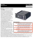
Synth Out
This connector will accept any MIDI cable to your synth, computer, or other
MIDI receiving device. Unlike the MIDIFly Out connector on the other side of
the PHANTOM POWER SUPPLY there is no power to Synth Out connector.
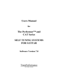
Connections on the MIDIFly
There are three connectors on the MIDIFly:
MIDI IN
MIDI IN
Stereo 1/4” phone jack.
AC Adapter Power
The "wall-wart" style AC adapter supplied with the MIDIFly is set for the proper voltage. Use of any other AC adapter is not recommended. When the
adapter is plugged into both the phantom power supply and an AC outlet, the
power LED should be on. There is no on\off switch anywhere on the MIDIFly
or the phantom power supply box.
MIDI In (nearest to the 1/4 in. phone jack)
This connector supplies two functions:
1) Allows the user to communicate commands to the unit for upgrading software and modifying the user configurable parameters by means of Sysex
messages (more on this later).
2) Allows for MIDI Thru capability to support the use of a breath controller or
similar device. The MIDI Thru capability is limited in that only Channel
Voice messages (hexadecimal 80...EF) are passed from input to output.
Any other messages will not be transmitted.
MIDI Controls
MIDI
Controls:
Synth Volume (located below the neck position pickup)
Adjustment of this control causes Channel Volume MIDI commands (controller #7) to be sent out for the MIDI channels currently selected.
MIDI Out (farthest from the 1/4 in. phone jack)
The supplied MIDI cable should be connected from the MIDI Out of the
MIDIFly to the junction box at one end with a MIDI connector and stereo
phone jack at the other. The MIDI connector plugs directly into the MIDI Out
on the Guitar. This is a special MIDI cable in that it supplies power to the
MIDIFly electronics from the junction box at the other end. All MIDI commands generated by the MIDIFly and passed from MIDI In are sent out this
connector.
Mode Switch (closest to the Synth Volume knob)
This 3-way switch selects one of three modes, Single Channel Mode with
pitch bend off, Single Channel Mode with pitch bend on, and Multi Channel
Mode with pitch bend on.
Mode 1 (Up Position) - In Single Channel Mode with pitch bend off all
strings output to the same channel with no pitch bend output. Default
channel is 1.
NOTE: Plugging the MIDI cables into the wrong connector will not cause damage to the
MIDIFly, it just will not work.
Mode 2 (Center Position) - Same as Mode 1 except that pitch bend
messages will be sent as long as only one note is on. If a second note is
turned on pitch bend is set to neutral and Mode 2 functions the same as
Mode 1.
Stereo Phone Jack
The MIDIFly generates two audio outputs. The output of the Magnetic pickups is on the tip of the stereo phone jack(???)while the output of the Piezo
pickups is on the ring of the stereo phone jack. A special active mixer/preamp
circuit is switched on when a cable is connected. This "Smart Switching" output jack, automatically senses whether the cable is stereo or mono. (More on
this in the Audio Controls section.)
Mode 3 (Down Position) - In this mode, each string outputs to a separate channel and pitch bend is always on. The default channels for strings
1 through 6 are MIDI channels 1 through 6 respectively.
NOTE: Because the MidiAxe™ MIDI conversion circuit receives its signal from the piezo
system, a cable must be plugged into the MIDIFly's output jack to switch on the piezo system and for the MIDI circuit to operate.
Octave Switch (farthest from the Synth Volume knob)
This 3-way switch shifts the notes up or down one octave. The center position is the normal, no octave shift, position. With the switch in the up position,
notes are shifted down an octave. In the down position, notes are shifted up
an octave.
The MIDIFly can operate as a "normal" guitar by plugging any standard guitar cable into the output jack even if the MIDI power supply is not connected.
Connections on the MIDIFly /MidiAxe Phantom
Power Supply
The MIDI Power Supply/junction box supplied with the MIDIFly has three
connections .....
MIDIFly Out
Synth Out
AC Adapter power in
MIDIFly Out
This connector will accept any MIDI cable and actually supplies power to the
MIDIFly's MidiAxe™ circuit as it receives the MIDIFlys MIDI out signal (then
transmitting it on to a connected MIDI synth).
2
P
a
r
k
e
r
®
M
I
D
I
F
l
y
™
Audio
AudioControls
Controls:
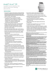
Battery
1. Magnetic pickup Volume - Nearest the bridge position pickup
Because the two kinds of pickups have "irreconcilable impedance differences," their outputs cannot be mixed without the help of an electrically powered (active) circuit. The 9 volt battery that powers the FISHMAN® Piezo preamplifier has a life of approximately 150 hours. The circuit switches on when
a cable is plugged into the guitar, so to conserve batteries, unplug the cable
when you're not playing your MIDIFLY.
2. Magnetic pickup Tone - Below the 3-position magnetic/both/piezo selector
switch
3. Five-Position Pickup Selector Switch.
4. Piezo Volume - Above the 3-position magnetic/both/piezo selector switch
NOTE: The active piezo system supplies the signal to the MidiAxe™ digital MIDI conversion circuit, so if a battery is low (or dead) MIDI tracking will be degraded or not operational.
5. 3-position magnetic/both/piezo selector switch - Between the Mag Tone
and Piezo volume
To replace the battery, release the catch and swing open the doors. The flipout holder will not close if the battery is installed incorrectly. Please be gentle!
This toggle switch has three positions:
Magnetic Pickups (toward the neck)
Both (middle position)
Piezo Pickups (toward the output jack)
Piezo Frequency Response
Piezo pickups have far greater treble response than magnetic pickups. Some
amps have no trouble with the additional high frequency output, but others
may distort. If this happens, either lower the Piezo volume at the guitar or
amp, or try lowering the treble control of the amp.
"Smart Switching" output jack
The MIDIFLY is equipped with both FISHMAN® Piezo and DiMarzio® magnetic pickups. A special active circuit featuring a "Smart Switching" output
jack, automatically senses whether a stereo or mono jack is inserted. This circuit makes it possible to mix (or sum) the piezo and magnetic pickup signals,
by automatically sensing the output cable, and play both sounds through a
single amp, or split them to two separate amps or mixers.
Ground Loops
Sometimes when using two amps, there may be a loud hum when the guitar
is plugged into the second amp. This hum is caused by a ground loop. This
ground loop isn't the fault of the guitar (or the amps for that matter), but rather
the result of essential electrical safety code requirements. Ground loops can
occur whenever two pieces of electronic equipment are connected.
1. Mono Guitar Cable
When a standard mono guitar cable is inserted, the guitar's two signals
(magnetic and piezo pickups) are automatically mixed or summed. Both
sounds can be played through a single guitar amplifier or mixer.
NOTE: Do Not Disconnect Or Otherwise Attempt To Defeat Ground Connections On Your
Electrical Equipment !!
2. Stereo Cable
When a stereo guitar cable is inserted, the guitar's two signals (magnetic
and piezo pickups) are automatically split in stereo. The special stereo to
Y cable provided with the guitar allows you to send the two signals to two
separate amplifiers. The Piezo pickup will sound its best through a PA, an
Acoustic Guitar amp, a Keyboard amp, or some other high-fidelity unit.
There is ONLY ONE safe way to rid yourself of ground loops .....
Use a Direct Box with a ground lift to isolate the two amps. Plug the Magnetic
end of the stereo "Y" mono cable into one amp and the Piezo end into the
Direct Box. Plug the Direct Box's output into a balanced input on the second
amp.
NOTE: An audio cable must be plugged into the MIDIFly's output jack for the MIDI circuit
to operate.
Piezo Balance Trim Pot
Your guitar is equipped with a Piezo Balance Trim Pot. We set this control at
the factory so that the full volume outputs of the Piezo and magnetic systems
are equal. Since string gauges and pickup height affect the output of the magnetic pickups, you may want to change the relative levels of the two systems
by adjusting the Piezo output.
To do this remove the three pickguard screws nearest the controls. Carefully
lift the pickguard and adjust the small,white control located on the
Stereo/Mono switch circuit board with a small screw driver. This "trim pot"
adjusts the output of the Piezo pickup.
3
P
a
r
k
e
r
®
M
I
D
I
F
l
y
™
Adjusting
your
MIDIFly
Adjusting
Your
MIDIFly
Truss Rod Adjustment
If you're unfamiliar with adjusting instruments, we suggest that you take your
MIDIFly to a qualified guitar technician. He or she can help demonstrate these
adjustments and you can decide which ones you are comfortable making
yourself and which ones you might prefer to have made professionally.
If you're unfamiliar with adjusting a truss rod, we STRONGLY suggest that you
have this adjustment made by a qualified guitar technician.
The truss rod adjuster wheel is easily accessible. To adjust the truss rod, use
the 1/8" steel rod supplied with your guitar. Rotate the wheel towards the high
E string to tighten the truss rod and towards the low E string to loosen it.
Vibrato Adjustment
Adjusting The Magnetic Pickups
Start from HOME: When the bridge is adjusted parallel to the top of the guitar and the guitar is in tune, the bridge is in the HOME position.
Each DiMarzio® pickup is held to the pickguard by two screws. These screws
also adjust the pickup's height. Turn the screws clockwise to raise and counterclockwise to lower the pickup.
MIDIFly guitars are set-up at the Parker Guitar Factory with D'Addario®
strings. Three coil springs balance the tension of the strings. When you
change string gauges or use alternate tunings, you alter the string tension.
This changes the attitude of the bridge, and therefore, you will need to readjust the bridge to the HOME position. To do this, remove the back cover,
and with the guitar tuned to pitch, tighten or loosen the two phillips head
''CLAW" screws to reset the bridge parallel to the top of the guitar.
The MIDIFLY Vibrato is a high quality, stable system that can be operated in
three MODES:
Intonation
To set the intonation (string length), loosen the screws that hold the bridge
saddles using the smaller T-handle Allen wrench supplied with the guitar. If a
string plays sharp, slide the saddle back to make the string longer. If it plays
flat, slide it forward. Do not over-tighten the saddle screws. The Piezo-electric
elements in the bridge are delicate, so be careful. The eraser end of a pencil
is a safe tool for sliding the saddles. No hitting!
1) Balanced
In this MODE the bridge can bend up and down ("free floating"). The Stop
Screw must be adjusted (lowered) so that it won't prevent the bridge from
bending up. The HOME position of the bridge is set by adjusting the CLAW
screws (balancing the tension of the coil springs).
Tuning Machines
We proudly use Sperzel® tuners-designed and manufactured in the USAbecause they combine excellent quality and design, the best string locking
system, and minimum weight. Sperzel's® patented string clamp eliminates the
need for tying and multiple string wraps, greatly improving tuning stability.
To remove a string, loosen the clamp knob at the back of the tuner. Before restringing, turn each tuner until the hole in the string post is in line with the
string path. Feed the string through, pull out the slack, tighten the clamp knob,
and tune up. You're doing it right if you end up with less than 1/4 of a full wrap
on each string post.
2) Bend Down
3) Fixed
This MODE is similar to the Bend Down MODE. HOME position is also set
by contact with the Stop Screw. Additional spring force is applied against
the stop by tightening the CLAW screws. The bridge will still bend down,
but with a stiffer feel. In this MODE you can bend a string while other
strings are sounded and not change their pitch. Like the Bend Down
MODE, resting your hand on the bridge will not throw it out of tune.
No matter which MODE you prefer to use, it's quickest to tune, set intonation,
and adjust the action of your MIDIFly in the Fixed MODE.
Frets
Our patented fret and fretboard system consists of hardened stainless steel
frets bonded to a glass and carbon fiber fretboard. Not only will these unique
frets outlast ordinary soft nickel frets, but due to our totally unique super-accurate manufacturing processes, they all have the correct "half-round" shape.
Stop Screw
Using the larger T-handle Allen wrench supplied with your guitar, the Stop
Screw can be adjusted to limit or stop the bridge from bending up to any
desired place.
NOTE: The frets may only be serviced at the Parker Guitar Factory or by a PGF
Authorized Repair Facility. Fret service performed otherwise will void the warranty.
NOTE: When you raise or lower the Action you should also raise or lower the Stop Screw
by the same amount (unless the Stop Screw has already been fully lowered for the
Balanced MODE).
Action
Action (bridge/string height) is adjusted by two screws from the back of the
guitar. Using the larger T-handle Allen wrench, turn the screws clockwise to
lower the bridge, and counterclockwise to raise it. Also, It's good practice to
alternate between the two screws, taking no more than 1/4 turn at a time.
4
P
a
r
k
e
r
®
M
I
D
I
F
l
y
™
CD-ROM
(PC) Editor:
Editor
MIDIFly CD
ROM (PC)
MidiAxe™ Utilities Rev 1.0
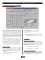
The MidiAxe™ Utilities Panel is a Windows 95/98/NT software program that
allows users to customize settings for their MidiAxe Equipped digital guitar,
check the status of the MidiAxe software, and provides a method for upgrading the guitar to future versions of the MidiAxe operating system software
(these software upgrades may be obtained from the MidiAxe website at
www.midiaxe.com). Most of the controls are on the panel map to simple MIDI
"System Exclusive" (SysEx) commands which can also be created using
other third party MIDI panel design tools or programmable hardware MIDI
control devices (see the MidiAxe User's Manual for the SysEx command
specification).
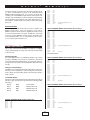
3) Follow the install dialog boxes for selection of the location
on your hard disk
4) When the install has completed, reboot the computer
and then select:
START ➩ PROGRAMS ➩ MIDIAXE UTILITIES
NOTE: If the setup fails or is cancelled, all temporary files will be removed from
the computer and the user may try again later.
All of the parameters of the MidiAxe that can be changed by panel controls
are programmed at the time of the change and remain in effect thereafter. If
the user gets lost or simply wants to return the guitar to the original configuration it is a simple operation to just hit the "Restore Defaults" button.
Panel Operation
Selecting the Proper System MIDI Interface
The first step to using the panel is to make sure the correct MIDI interface on
the computer is selected. There is a MIDI I/O selection pull down list in the
upper right hand corner of the panel. Select the desired MIDI input and MIDI
output device appropriate for your computer and make sure the MidiAxe™
Equipped guitar is connected as follows:
NOTE: Normally most MidiAxe users will not normally need to use this panel because
the most common controls are preset at the factory for easy plug and play operation.
However, because each user may want to customize his or her guitar parameters, the
MidiAxe Utilities are provided to make for a completely programmable MIDI Guitar system.
Software Installation
➩ Computer MIDI IN
➩ Computer MIDI OUT
MidiAxe Guitar MIDI OUT
Each MidiAxe™ Equipped guitar is shipped with a CD containing this utility
which enables the more technical user to access some of the programmable
features of the MidiAxe Equipped system. The install is accomplished by
inserting the CD in the CD-ROM drive and using Windows Explorer to locate
the setup program.
Steps:
1) Insert the MidiAxe™ Utilities CD into the CD ROM Drive
2) Double Click on "setup.exe"
MidiAxe Guitar MIDI IN
Initializing the Panel to the MidiAxe Settings
The next step in using the MidiAxe™ Utilities panel is to press the INITIALIZE
button. This tells the MidiAxe™ Equipped guitar to upload all of its current settings to the panel including the software version information, serial numbers,
and the current control settings for all of the programmable parameters.
5
P
a
r
k
e
r
®
M
I
D
I
F
l
y
™
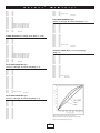
ear response to plucking the strings. Note that the "attack" profile of a synthesized sound varies widely with manufactures and patch settings and this
enters into the velocity mapping perception.
Making Changes
Any of the controls may be changed, and each time a control is moved new
SysEx commands are sent to the guitar and stored. This way if the power is
disconnected during any utilities session the changes will be remembered.
String Sensitivity
In addition to the global velocity setting, each individual string sensitivity can
be adjusted to suit individual tastes for picking hardness, etc. This is optimally
adjusted to 100% for each string by default, but each string can be set accordingly. While adjusting the string setting, the user may view the signal strength
on the VU meter panel.
Panel Controls
Panel
Controls
MIDI I/O Select
Use the pull down list control for each of the Input and Output devices to
select the appropriate device connected to the MidiAxe™ Equipped guitar.
Once the devices are selected, when the utility panel is shut down, they will
be remembered the next time the panel is started.
Synth Volume
On the bottom of the panel there is a Synth Volume setting VU meter which
provides for an easy way to see if the MidiAxe™ System is connected properly to the panel and messages are being transmitting and received. By moving the Synth Volume Pot on the guitar the bar graph should vary smoothly
from 0% to 100%.
MIDI Channel Selection
There are two basic MIDI transmission modes the MidiAxe™ system performs. The first is the single channel mode whereby all strings transmit on a
single MIDI channel (3 way toggle switch in the middle or up position). The
default channel programmed at the factory is channel 1. The second mode is
multi-channel mode (also known as MIDI Mono mode), whereby each string
is assigned an independent MIDI channel (3 way toggle switch in the down
position). The default channels programmed at the factory for this mode are
MIDI channels 1-6 corresponding to strings 1-6. Using the UP/DOWN buttons
the user may change the MIDI channel for any of the strings in the respective
modes.
VU Meters
The VU meter portion of the panel shows the relative loudness of each string
as a user plucks it. This isn't the actual signal value, but rather the MIDI velocity that is shown on the VU meter. In single channel mode, only one VU meter
bar (bottom one) will be active for any of the strings. In multi-channel mode
each of the string's velocity values will cause the corresponding VU meter bar
to show signal strength (velocity).
Initialize Button and Version Status
Pitch Bend Range Select
As described above in the Panel Operation summary, the INITIALIZE button
is pressed to initialize the panel to the setting of the MidiAxe™ system once
the guitar has been connected properly. On the lower right hand portion of
the screen, firmware version number, software version number, guitar serial
number, and MidiAxe™ circuit board serial number are displayed. For software updates, the "software" version is the number to the left of the "/" character on the version status panel.
When the 3 way MIDI mode toggle switch is in the middle or down position,
the MidiAxe™ system sends pitch bend messages when a note is bent up or
down. In this case, MIDI pitch bend messages are sent on the appropriate
MIDI channel. If the MIDI mode is "single channel" the pitch bend message
will be sent only on that corresponding MIDI channel. If the MIDI mode is
multi-channel, then the pitch bend message will be sent on all 6 MIDI channels. The pitch bend range refers to how many semitones of synth pitch bend
correspond to a full-scale pitch bend coming from the guitar. It is essential,
for normal operation, that the guitar's pitch bend range corresponds to the
synth's pitch bend range. By default most synths are set to +/- 2 semitones
of pitch bend range for the full scale range of the instrument pitch bend. This
is why the MidiAxe™ system is shipped from the factory set to this +/- 2 semitone range. The user may increase or decrease the pitch bend range by
pressing the UP/DOWN buttons.
Tuner
A "guitar tuner" utility is provided that allows the user to tune the guitar via the
MidiAxe™ Utilities panel. This tuner uses pitch bend messages to signal tuning information. Once the Tuner button is pressed, a small LED panel is presented with a Green LED in the center and RED LED's to the right and left of
the center Green LED. A letter note also lets the user know what is the closest chromatic note being played. The user should adjust the pitch (using the
guitar tuning keys) until the corresponding chromatic note is correct and the
Green LED is showing. Note that heavy picking temporarily causes a slightly sharp tuning, so using a lighter picking stroke during tuning will result in a
more "in-tune" guitar.
NOTE: The MidiAxe™ system will automatically send "PITCH BEND GAIN" information
to any synth connected to the guitar when the "OCTAVE" switch is moved to any position.
This may be a quick way to make sure the synth is tracking the pitch bend range correctly. Beware however that not all synths respond to this message, and you may have to
resort to manually programming the pitch bend range on the synth.
Velocity Curve Select
Restore Defaults Button
The velocity curve controls how "punchy" the synth sound is relative to how
the user picks or plucks the string with his or her finger or pick. The MidiAxe™
system is shipped from the factory with a "hot" velocity curve profile that we
have found to be the most universally preferred velocity mapping for most
people. However some users may prefer a more "linear" feel to this velocity
profile. There are 3 curves selectable with the curve 1 corresponding to the
most "linear" and curve 3 corresponding to the most "compressed" or non-lin-
The Restore Defaults button allows a user to set all of the MidiAxe™ system
parameters back to the original manufactured state.
Upgrade Button
The Upgrade button is used to update the operating system software for the
MidiAxe™ Equipped guitar. When the button is pressed a dialog menu is pre-
6
P
a
r
k
e
r
®
M
sented and a specially coded software file is selected for download to the guitar. This is a special SysEx file (.syx) and can be downloaded from the
MidiAxe™ website (www.midiaxe.com). Use of any other .syx file will cause
overwriting of the internal MidiAxe program memories and should never be
attempted. If this should happen, use the Recovery button and then Upgrade
with the appropriate software SysEx file. The software upgrade takes a couple of minutes to complete and the user should never remove power during
this process.
I
Byte 11:
Byte 12:
Byte 13:
Byte 14:
Byte 15:
Byte 16:
Byte 17:
Byte 18:
Byte 19:
Byte 20:
Byte 21:
Byte 22:
Byte 23:
D
I
0x00
0x00
0x00
0x0A
0x03
0x02
0x00
0x00
0x00
0x00
0x00
Channel #
0xF7
F
l
y
™
Selected Channel Number (0x00...0x0F)
End of Sysex
Recovery Button
MULTI CHANNEL MODE, Channel number select for String 1
The Recovery button should only be used as a result of a corruption of the
MidiAxe™ system memory. In this case, this button is used to put the
MidiAxe™ system into a known state prior to upgrading the software as a way
to restore the internal memory of the system. Normally this is only used by
the factory to set up the MidiAxe™ system the first time, and would not be a
control frequently used by a user. It is only provided as a fail safe way to
recover a crashed system should that occur.
Byte 4:
Byte 5:
Byte 6:
Byte 7:
Byte 8:
Byte 9:
Byte 10:
Byte 11:
Byte 12:
Byte 13:
Byte 14:
Byte 15:
Byte 16:
Byte 17:
Byte 18:
Byte 19:
Byte 20:
Byte 21:
Byte 22:
Byte 23:
SYSEX
SYSEXSpecification
Specification:
The user may communicate with the MIDIFly for the purposes of upgrading
software and modifying the user settings. This section will set forth the details
for these functions.
0x21
0x00
0x02
0x00
0x00
0x00
0x01
0x00
0x00
0x00
0x02
0x09
0x0D
0x00
Channel #
0x00
0x00
0x00
0x00
0xF7
Selected Channel Number (0x00...0x0F)
End of Sysex
MIDI CONTROLLER NUMBERS
Software Upgrade
The software upgrade feature is accomplished by sending a series of Sysex
messages to the MIDIFly. The messages are contained in a single file that
can be downloaded from the MIDIFly website. The software that sends these
messages must insert a delay of at least 150ms(milliseconds) between each
message.
MULTI CHANNEL MODE, Channel number select for String 2
Byte 4:
Byte 5:
Byte 6:
Byte 7:
Byte 8:
Byte 9:
Byte 10:
Byte 11:
Byte 12:
Byte 13:
Byte 14:
Byte 15:
Byte 16:
Byte 17:
Byte 18:
Byte 19:
Byte 20:
Byte 21:
Byte 22:
Byte 23:
Changes to User Settings
The MIDIFly comes programmed with default settings that are optimal for a
wide range of users. Through the use of Sysex messages the user may modify these settings. The default settings may be restored at any time through a
single command.
The SYSEX Details
All values are expressed in hexidecimal format, indicated by '0x' preceding an
8 bit value (1 byte). Each Sysex message must have the following preamble
(first 4 bytes).
Byte 0:
0xF0
Sysex Status
Byte 1:
0x00
Manufacturer's ID
Byte 2:
0x01
Manufacturer's ID
Byte 3:
0x25
Manufacturer's ID
Selected Channel Number (0x00...0x0F)
End of Sysex
MULTI CHANNEL MODE, Channel number select for String 3
Byte 4:
Byte 5:
Byte 6:
Byte 7:
Byte 8:
Byte 9:
Byte 10:
Byte 11:
Byte 12:
Byte 13:
Byte 14:
Byte 15:
Byte 16:
Byte 17:
Byte 18:
Byte 19:
Byte 20:
Byte 21:
Byte 22:
Byte 23:
SINGLE CHANNEL MODE, Channel number select
Byte 4:
Byte 5:
Byte 6:
Byte 7:
Byte 8:
Byte 9:
Byte 10:
0x22
0x00
0x02
0x00
0x00
0x00
0x01
0x00
0x00
0x00
0x00
0x09
0x0D
0x00
Channel #
0x00
0x00
0x00
0x00
0xF7
0x27
0x00
0x00
0x00
0x00
0x00
0x01
7
0x23
0x00
0x01
0x00
0x00
0x00
0x01
0x00
0x00
0x00
0x02
0x09
0x0D
0x00
Channel #
0x00
0x00
0x00
0x00
0xF7
Selected Channel Number (0x00...0x0F)
End of Sysex
P
a
r
k
e
r
®
M
MULTI CHANNEL MODE, Channel number select for String 4
Byte 4:
Byte 5:
Byte 6:
Byte 7:
Byte 8:
Byte 9:
Byte 10:
Byte 11:
Byte 12:
Byte 13:
Byte 14:
Byte 15:
Byte 16:
Byte 17:
Byte 18:
Byte 19:
Byte 20:
Byte 21:
Byte 22:
Byte 23:
0x24
0x00
0x01
0x00
0x00
0x00
0x01
0x00
0x00
0x00
0x00
0x09
0x0D
0x00
Channel #
0x00
0x00
0x00
0x00
0xF7
Byte 17:
Byte 18:
Byte 19:
Byte 20:
Byte 21:
Byte 22:
Byte 23:
0x25
0x00
0x00
0x00
0x00
0x00
0x01
0x00
0x00
0x00
0x02
0x09
0x0D
0x00
Channel #
0x00
0x00
0x00
0x00
0xF7
Byte 4:
Byte 5:
Byte 6:
Byte 7:
Byte 8:
Byte 9:
Byte 10:
Byte 11:
Byte 12:
Byte 13:
Byte 14:
Byte 15:
Byte 16:
Byte 17:
Byte 18:
Byte 19:
Byte 20:
Byte 21:
Byte 22:
Byte 23:
Selected Channel Number (0x00...0x0F)
End of Sysex
0x26
0x00
0x00
0x00
0x00
0x00
0x01
0x00
0x00
0x00
0x00
0x09
0x0D
0x00
Channel #
0x00
0x00
0x00
0x00
0xF7
Byte 4:
Byte 5:
Byte 6:
Byte 7:
Byte 8:
Byte 9:
Byte 10:
Byte 11:
Byte 12:
Byte 13:
Byte 14:
Byte 15:
Byte 16:
Byte 17:
Byte 18:
Byte 19:
Byte 20:
Byte 21:
Byte 22:
Byte 23:
Selected Channel Number (0x00...0x0F)
End of Sysex
F
l
y
™
DATA BITS (15...12) in lower nibble (0x00...0x07)
DATA BITS (11...8) in lower nibble (0x00...0x0F)
DATA BITS (7…4) in lower nibble (0x00...0x0F)
DATA BITS (3…0) in lower nibble (0x00...0x0F)
0x00
0x00
0xF7
End of Sysex
0x20
0x00
0x02
0x00
0x00
0x00
0x01
0x00
0x00
0x00
0x00
0x09
0x0A
DATA BITS (15...12) in lower nibble (0x00...0x07)
DATA BITS (11...8) in lower nibble (0x00...0x0F)
DATA BITS (7…4) in lower nibble (0x00...0x0F)
DATA BITS (3…0) in lower nibble (0x00...0x0F)
0x00
0x00
0xF7
End of Sysex
0x20
0x00
0x01
0x00
0x00
0x00
0x01
0x00
0x00
0x00
0x02
0x09
0x0A
DATA BITS (15...12) in lower nibble (0x00...0x07)
DATA BITS (11...8) in lower nibble (0x00...0x0F)
DATA BITS (7…4) in lower nibble (0x00...0x0F)
DATA BITS (3…0) in lower nibble (0x00...0x0F)
0x00
0x00
0xF7
End of Sysex
STRING SENSITIVITY, for String 4 (16 bits, Range = 0...0x7fff)
Byte 4:
Byte 5:
Byte 6:
Byte 7:
Byte 8:
Byte 9:
Byte 10:
Byte 11:
Byte 12:
Byte 13:
Byte 14:
Byte 15:
Byte 16:
Byte 17:
Byte 18:
Byte 19:
Byte 20:
Byte 21:
Byte 22:
Byte 23:
Selected Channel Number (0x00...0x0F)
End of Sysex
STRING SENSITIVITY, for String 1 (16 bits, Range = 0...0x7fff)
Byte 4:
Byte 5:
Byte 6:
Byte 7:
Byte 8:
Byte 9:
Byte 10:
Byte 11:
Byte 12:
Byte 13:
Byte 14:
Byte 15:
Byte 16:
I
STRING SENSITIVITY, for String 3 (16 bits, Range = 0...0x7fff)
MULTI CHANNEL MODE, Channel number select for String 6
Byte 4:
Byte 5:
Byte 6:
Byte 7:
Byte 8:
Byte 9:
Byte 10:
Byte 11:
Byte 12:
Byte 13:
Byte 14:
Byte 15:
Byte 16:
Byte 17:
Byte 18:
Byte 19:
Byte 20:
Byte 21:
Byte 22:
Byte 23:
D
STRING SENSITIVITY, for String 2 (16 bits, Range = 0...0x7fff)
MULTI CHANNEL MODE, Channel number select for String 5
Byte 4:
Byte 5:
Byte 6:
Byte 7:
Byte 8:
Byte 9:
Byte 10:
Byte 11:
Byte 12:
Byte 13:
Byte 14:
Byte 15:
Byte 16:
Byte 17:
Byte 18:
Byte 19:
Byte 20:
Byte 21:
Byte 22:
Byte 23:
I
0x20
0x00
0x02
0x00
0x00
0x00
0x01
0x00
0x00
0x00
0x02
0x09
0x0A
0x20
0x00
0x01
0x00
0x00
0x00
0x01
0x00
0x00
0x00
0x00
0x09
0x0A
DATA BITS (15...12) in lower nibble (0x00...0x07)
DATA BITS (11...8) in lower nibble (0x00...0x0F)
DATA BITS (7…4) in lower nibble (0x00...0x0F)
DATA BITS (3…0) in lower nibble (0x00...0x0F)
0x00
0x00
0xF7
End of Sysex
STRING SENSITIVITY, for String 5 (16 bits, Range = 0...0x7fff)
Byte 4:
Byte 5:
Byte 6:
8
0x20
0x00
0x00
P
Byte 7:
Byte 8:
Byte 9:
Byte 10:
Byte 11:
Byte 12:
Byte 13:
Byte 14:
Byte 15:
Byte 16:
Byte 17:
Byte 18:
Byte 19:
Byte 20:
Byte 21:
Byte 22:
Byte 23:
a
r
k
e
r
®
M
Byte 20:
Byte 21:
Byte 22:
Byte 23:
0x00
0x00
0x00
0x01
0x00
0x00
0x00
0x02
0x09
0x0A
DATA BITS (15...12) in lower nibble (0x00...0x07)
DATA BITS (11...8) in lower nibble (0x00...0x0F)
DATA BITS (7…4) in lower nibble (0x00...0x0F)
DATA BITS (3…0) in lower nibble (0x00...0x0F)
0x00
0x00
0xF7
End of Sysex
Byte 4:
Byte 5:
Byte 6:
Byte 7:
Byte 8:
Byte 9:
Byte 10:
Byte 11:
Byte 12:
Byte 13:
Byte 14:
Byte 15:
Byte 16:
Byte 17:
Byte 18:
Byte 19:
Byte 20:
Byte 21:
Byte 22:
Byte 23:
0x20
0x00
0x00
0x00
0x00
0x00
0x01
0x00
0x00
0x00
0x00
0x09
0x0A
DATA BITS (15...12) in lower nibble (0x00…0x07)
DATA BITS (11...8) in lower nibble (0x00…0x0F)
DATA BITS (7…4) in lower nibble (0x00...0x0F)
DATA BITS (3…0) in lower nibble (0x00...0x0F)
0x00
0x00
0xF7
End of Sysex
0x20
0x00
0x00
0x00
0x00
0x00
0x01
0x00
0x00
0x00
0x0A
0x00
0x0D
0x00
0x00
0x00
0x00
0x00
range value (0x00…0x06)
0xF7
I
F
l
0x00
0x00
range value (0x00...0x06)
0xF7
y
™
End of Sysex
0x20
0x00
0x02
0x00
0x00
0x00
0x01
0x00
0x00
0x00
0x0A
0x00
0x0D
0x00
0x00
0x00
0x00
0x00
range value (0x00...0x06)
0xF7
End of Sysex
VELOCITY CURVE (Selects 1 of 3 velocity mappings)
(Range = 0…2)
Byte 4:
Byte 5:
Byte 6:
Byte 7:
Byte 8:
Byte 9:
Byte 10:
Byte 11:
Byte 12:
Byte 13:
Byte 14:
Byte 15:
Byte 16:
Byte 17:
Byte 18:
Byte 19:
Byte 20:
Byte 21:
Byte 22:
Byte 23:
PITCH BEND RANGE Message 1
(Consists of 3 messages, all 3 must be sent) (Range = 0...6)
Byte 4:
Byte 5:
Byte 6:
Byte 7:
Byte 8:
Byte 9:
Byte 10:
Byte 11:
Byte 12:
Byte 13:
Byte 14:
Byte 15:
Byte 16:
Byte 17:
Byte 18:
Byte 19:
Byte 20:
Byte 21:
Byte 22:
Byte 23:
D
PITCH BEND RANGE Message 3
(Consists of 3 messages, all 3 must be sent) (Range = 0...6)
STRING SENSITIVITY, for String 6 (16 bits, Range = 0...0x7fff)
Byte 4:
Byte 5:
Byte 6:
Byte 7:
Byte 8:
Byte 9:
Byte 10:
Byte 11:
Byte 12:
Byte 13:
Byte 14:
Byte 15:
Byte 16:
Byte 17:
Byte 18:
Byte 19:
Byte 20:
Byte 21:
Byte 22:
Byte 23:
I
0x20
0x00
0x00
0x00
0x00
0x00
0x01
0x00
0x00
0x00
0x0A
0x00
0x0C
0x00
0x00
0x00
0x00
0x00
curve number (0x00...0x02)
0xF7
End of Sysex
End of Sysex
PITCH BEND RANGE Message 2
(Consists of 3 messages, all 3 must be sent) (Range = 0...6)
Byte 4:
Byte 5:
Byte 6:
Byte 7:
Byte 8:
Byte 9:
Byte 10:
Byte 11:
Byte 12:
Byte 13:
Byte 14:
Byte 15:
Byte 16:
Byte 17:
Byte 18:
Byte 19:
0x20
0x00
0x01
0x00
0x00
0x00
0x01
0x00
0x00
0x00
0x0A
0x00
0x0D
0x00
0x00
0x00
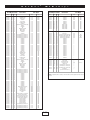
Table 3: Controller and Mode Changes (Status Bytes 176-191)
(adapted from "MIDI by the Numbers" by D. Valenti-Electronic Musician 2/88)
Updated 1995 By the MIDI Manufacturers Association
9
P
2nd Byte Value
Binary
Hex
Dec
00000000 =
00000001 =
00000010 =
00000011 =
00000100 =
00000101 =
00000110 =
00000111 =
00001000 =
00001001 =
00001010 =
00001011 =
00001100 =
00001101 =
00001110 =
00001111 =
00010000 =
00010001 =
00010010 =
00010011 =
00010100 =
00010101 =
00010110 =
00010111 =
00011000 =
00011001 =
00011010 =
00011011 =
00011100 =
00011101 =
00011110 =
00011111 =
00100000 =
00100001 =
00100010 =
00100011 =
00100100 =
00100101 =
00100110 =
00100111 =
00101000 =
00101001 =
00101010 =
00101011 =
00101100 =
00101101 =
00101110 =
00101111 =
00110000 =
00110001 =
00110010 =
00110011 =
00110100 =
00110101 =
00110110 =
00110111 =
00111000 =
00111001 =
00111010 =
00111011 =
00111100 =
00111101 =
00111110 =
00111111 =
01000000 =
01000001 =
01000010 =
01000011 =
01000100 =
01000101 =
01000110 =
01000111 =
01001000 =
01001001 =
01001010 =
01001011 =
01001100 =
01001101 =
01001110 =
01001111 =
01010000 =
01010001 =
01010010 =
01010011 =
00 =
01 =
02 =
03 =
04 =
05 =
06 =
07 =
08 =
09 =
0A =
0B =
0C =
0D =
0E =
0F =
10 =
11 =
12 =
13 =
14 =
15 =
16 =
17 =
18 =
19 =
1A =
1B =
1C =
1D =
1E =
1F =
20 =
21 =
22 =
23 =
24 =
25 =
26 =
27 =
28 =
29 =
2A =
2B =
2C =
2D =
2E =
2F =
30 =
31 =
32 =
33 =
34 =
35 =
36 =
37 =
38 =
39 =
3A =
3B =
3C =
3D =
3E =
3F =
40 =
41 =
42 =
43 =
44 =
45 =
46 =
47 =
48 =
49 =
4A =
4B =
4C =
4D =
4E =
4F =
50 =
51 =
52 =
53 =
0
1
2
3
4
5
6
7
8
9
10
11
12
13
14
15
16
17
18
19
20
21
22
23
24
25
26
27
28
29
30
31
32
33
34
35
36
37
38
39
40
41
42
43
44
45
46
47
48
49
50
51
52
53
54
55
56
57
58
59
60
61
62
63
64
65
66
67
68
69
70
71
72
73
74
75
76
77
78
79
80
81
82
83
a
r
k
Function
Bank Select
Modulation wheel
Breath control
Undefined
Foot controller
Portamento time
Data Entry
Channel Volume (formerly Main Volume)
Balance
Undefined
Pan
Expression Controller
Effect Control 1
Effect Control 2
Undefined
Undefined
General Purpose Controller #1
General Purpose Controller #2
General Purpose Controller #3
General Purpose Controller #4
Undefined
Undefined
Undefined
Undefined
Undefined
Undefined
Undefined
Undefined
Undefined
Undefined
Undefined
Undefined
Bank Select
Modulation wheel
Breath control
Undefined
Foot controller
Portamento time
Data entry
Channel Volume (formerly Main Volume)
Balance
Undefined
Pan
Expression Controller
Effect Control 1
Effect Control 2
Undefined
Undefined
General Purpose Controller #1
General Purpose Controller #2
General Purpose Controller #3
General Purpose Controller #4
Undefined
Undefined
Undefined
Undefined
Undefined
Undefined
Undefined
Undefined
Undefined
Undefined
Undefined
Undefined
Damper Pedal on/off (Sustain)
Portamento on/off
Sustenuto on/off
Soft Pedal on/off
Legato Footswitch
Hold 2
Sound Controller 1 (Sound Variation)
Sound Controller 2 (Timbre)
Sound Controller 3 (Release Time)
Sound Controller 4 (Attack Time)
Sound Controller 5 (Brightness)
Sound Controller 6
Sound Controller 7
Sound Controller 8
Sound Controller 9
Sound Controller 10
General Purpose Controller #5
General Purpose Controller #6
General Purpose Controller #7
General Purpose Controller #8
e
r
®
M
3rd Byte
I
D
I
F
2nd Byte Value
Value
Use
Binary
Hex
Dec
0-127
0-127
0-127
0-127
0-127
0-127
0-127
0-127
0-127
0-127
0-127
0-127
0-127
0-127
0-127
0-127
0-127
0-127
0-127
0-127
0-127
0-127
0-127
0-127
0-127
0-127
0-127
0-127
0-127
0-127
0-127
0-127
0-127
0-127
0-127
0-127
0-127
0-127
0-127
0-127
0-127
0-127
0-127
0-127
0-127
0-127
0-127
0-127
0-127
0-127
0-127
0-127
0-127
0-127
0-127
0-127
0-127
0-127
0-127
0-127
0-127
0-127
0-127
0-127
<63=off
<63=off
<63=off
<63=off
<63=off
<63=off
0-127
0-127
0-127
0-127
0-127
0-127
0-127
0-127
0-127
0-127
0-127
0-127
0-127
0-127
MSB
MSB
MSB
MSB
MSB
MSB
MSB
MSB
MSB
MSB
MSB
MSB
MSB
MSB
MSB
MSB
MSB
MSB
MSB
MSB
MSB
MSB
MSB
MSB
MSB
MSB
MSB
MSB
MSB
MSB
MSB
MSB
LSB
LSB
LSB
LSB
LSB
LSB
LSB
LSB
LSB
LSB
LSB
LSB
LSB
LSB
LSB
LSB
LSB
LSB
LSB
LSB
LSB
LSB
LSB
LSB
LSB
LSB
LSB
LSB
LSB
LSB
LSB
LSB
>64=on
>64=on
>64=on
>64=on
>64=on
>64=on
LSB
LSB
LSB
LSB
LSB
LSB
LSB
LSB
LSB
LSB
LSB
LSB
LSB
LSB
01010100 =
01010101 =
01010110 =
01010111 =
01011000 =
01011001 =
01011010 =
01011011 =
01011100 =
01011101 =
01011110 =
01011111 =
54 =
55 =
56 =
57 =
58 =
59 =
5A =
5B =
5C =
5D =
5E =
5F =
84
85
86
87
88
89
90
91
92
93
94
95
01100000 =
01100001 =
01100010 =
01100011 =
01100100 =
01100101 =
01100110 =
01100111 =
01101000 =
01101001 =
01101010 =
01101011 =
01101100 =
01101101 =
01101110 =
01101111 =
01110000 =
01110001 =
01110010 =
01110011 =
01110100 =
01110101 =
01110110 =
01110111 =
60 =
61 =
62 =
63 =
64 =
65 =
66 =
67 =
68 =
69 =
6A =
6B =
6C =
6D =
6E =
6F =
70 =
71 =
72 =
73 =
74 =
75 =
76 =
77 =
96
97
98
99
100
101
102
103
104
105
106
107
108
109
110
111
112
113
114
115
116
117
118
119
01111000 =
01111001 =
01111010 =
01111011 =
01111100 =
01111101 =
78=
79=
7A=
7B=
7C=
7D=
01111110 =
01111111 =
l
y
™
Function
3rd Byte
Value
Use
Portamento Control
Undefined
Undefined
Undefined
Undefined
Undefined
Undefined
Effects 1 Depth
Effects 2 Depth
Effects 3 Depth
Effects 4 Depth
Effects 5 Depth
0-127
0-127
0-127
0-127
0-127
0-127
0-127
0-127
0-127
0-127
0-127
0-127
Source Note
LSB
LSB
LSB
LSB
LSB
LSB
LSB
LSB
LSB
LSB
LSB
Data entry +1
Data entry -1
Undefined
Undefined
Undefined
Undefined
Undefined
Undefined
Undefined
Undefined
Undefined
Undefined
Undefined
Undefined
Undefined
Undefined
Undefined
Undefined
Undefined
Undefined
N/A
N/A
0-127
0-127
0-127
0-127
?
?
?
?
?
?
?
?
?
?
?
?
?
?
?
?
?
?
120
121
122
123
124
125
All Sound Off
Reset All Controllers
Local Control on/off
All Notes off
Omni Mode off (+ all notes off)
Omni Mode on (+ all notes off)
0
0
0 = off
0
0
0
7E=
126
Poly Mode on/off (+ all notes off)
*
7F=
127
Poly Mode on
(incl mono=off +all notes off)
0
Non-Registered Parameter Number LSB
Non-Registered Parameter Number MSB
Registered Parameter Number LSB
Registered Parameter Number MSB
LSB
MSB
LSB
MSB
127 = on
*NOTE: This equals the number of channels, or zero if the number of channels equals the number of voices in
the receiver.
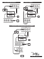
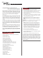
1 0
1 - Using a MIDI Sound Source
2 - Using a Computer
GUITAR
GUITAR
1/4"
Instrument Cable
MIDI
MIDI
MIDI
ON
IN
OUT
1/4"
Instrument Cable
AMP
AMP
MIDI
MIDI
MIDI
ON
IN
OUT
AMP
AMP
power
power
synth
MIDI Cable
guitar
synth
E q u i p p e d
E q u i p p e d
use only 9V 1A
AC
Power
Supply
a c adapter
use only 9V 1A
OUT
THRU
AC
Power
Supply
a c adapter
COMPUTER
SOUND CARD
MIDI KEYBOARD
SOUND SOURCE
IN
MIDI Cable
guitar
TM
TM
IN
OUTPUT
OUT
THRU
AMP
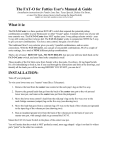
3 - Using BOTH a MIDI Sound Source and a Computer
GUIT
AR
1/4"
Instrument Cable
AMP
MIDI
MIDI
MIDI
ON
IN
OUT
AMP
power
synth
guitar
MIDI Cable
TM
E q u i p p e d
use only 9V 1A
a c adapter
AC
Power
Supply
MIDI KEYBOARD
SOUND SOURCE
IN
OUT
THRU
OUTPUT
AMP
COUMPUTER
SOUND CARD
IN
OUT
THRU
®
1 1
M
I
D
I
F
l
y
®