1
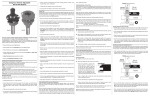
US Patent Pending
WARNING
Failure to obey these warnings could lead to serious bodily injury or death.
• Always wear eye protection complying with cur1
Constructing The Box Joint Jig
a) The SBOX8 Box Joint Cutter Set should be
used with a box joint jig for best results. A simple,
effective box joint jig can be made using these
instructions. Plans and instructions are also
available from commercial sources and
magazines and commercially produced
jigs are available.
c) Next cut a piece of 3/4" plywood to 24" X 6".
Turn the saw off, disconnect the power to the
machine and stand this piece on the long
edge with one face against the miter
gauge of the saw. Set the table saw fence
to 12". Place the two hardwood pieces from
step b side by side against the fence and butt
the plywood to them so that there is a space
b) A separate jig must be constructed for
each pin size. Disconnect the power to the
the two hardwood pieces and slide the plywood
over to the fence. Clamp the plywood to the miter
gauge and mark the location of the holes in the
miter gauge that will be used to mount the plywood. Remove the plywood and drill and counter
bore the mounting holes. Attach the plywood to
the miter gauge, ensuring that the heads of the
mounting bolts do not extend beyond the face of
the plywood. Next, move the saw fence at least
1" away from the jig for safety clearance.
between the fence and the plywood that is equal
to twice the pin width.
d) Set the cutter height to the same as the cutter width (d-1). Reconnect the power to the
machine and turn on the saw. Use the miter
gauge to slide the plywood over the cutter to
make a slot. Turn the saw off and slide the jig
back to the starting position (d-2).
(d-1) Set The Cutter Height
1/4"
Remove The
Hardwood Keys
3/8"
or
3/8"
1/4"
SAW
TABLE
TOP
(e)
SAMPLE WOOD
TO BE CUT
SAMPLE WOOD
TO BE CUT
SAW
TABLE
TOP
Slide To Fence
CUTTER
SBOX8 Box Joint Instructions
Thank you for choosing the Freud SBOX8
Box Joint Cutter Set. These premium quality,
patent pending cutters are easy to use and will produce consistently flawless box joints in all wood
and wood products. The instructions that follow will
guide you through building a simple jig to use with
your table saw’s miter gauge and completing
finished joints. Be sure to read and understand all
warnings and instructions before using these
cutters.
machine and set up the cutters for the desired
pin width. Reconnect power to the machine, turn
the saw on and make a sample cut in scrap
stock. Next machine a strip of hardwood to the
same width and height as the sample cut and at
least 5" long. Check the fit of the strip in the sample slot. When properly sized the strip will fit
snugly but will not require force. Cut the strip into
two pieces 2-1/2" long. One of these will be used
as the reference key and should be lightly chamfered on the edges.
any contact between the throat plate and cutter.
• Properly secure work piece before cutting.
• Allow saw to reach full speed before cutting.
• If you ever have any questions regarding your
blade, please call Freud Customer Service at 800472-7307. In Canada call 800-263-7016.
• Keep these warnings and instructions in a safe
place for future reference.
CUTTER
rent CSA standard Z94.1 or ANSI Standard Z87.1.
• Carbide is a very hard and brittle material. Slight
shocks can damage the carbide. Before each use,
check that the cutter is sharp and free from cracks,
loose teeth, missing teeth, broken teeth or any other
damage. Do not use if the cutter is dull or any damage is noticed or suspected.
• Use the cutter only for cutting wood. Do not use for
cutting metal, masonry, or concrete.
• Keep body, clothing and hair clear of spinning
blade. Do not wear jewelry while operating cutter.
Keep hands away from cutter and cutting area.
Never perform operations free hand.
• Always use both blades.
• Mount cutter securely in proper rotation direction indicated on the face of the blade itself.
• Never use cutter in the saw machine that will
exceed maximum recommended blade RPM
indicated on the cutter.
• Never use cutter in the vicinity of small children.
• Read and obey all warnings and instructions contained in saw machine's user's manual and for any
accessory that is from the manufacturer before
using the cutter. Be sure that this cutter is compatible with your saw machine. If you do not have the
user's manual, obtain one from the machine's manufacturer before using cutter.
• Only operate saw machine when proper saw
guards and protections are in place and working
properly.
• Always check clearance on throat plate before
connecting power to the saw. Do not use if there is
®
(d-2) Cut The Slot
(c)
(b)
Scr
Mill the key to
fit the test cut
Ha
rd
od
wo
Ke
y
2-1
2
"
-1/2
ap
Sto
ck
f) Glue the key into the slot with the end flush with
the back face of the plywood.
Set
Fence
Stop
To
Cu
(f)
12"
t
/2"
2 Hardwood Pins
Side by Side
5"
2 Hardwood Pins
Side by Side
2
Glue Hardwood
Key Flush With
The Back & Bottom
Of The Plywood Jig.
The Key Should
Protrude The Front
As Seen Here.
e) Disconnect the power to the machine. Remove
3
cutter are not in contact with the other cutter.
Set the cutter height 1/64" higher than the
thickness of the material to be joined.
Cutting the Joints
A) Begin by determining the width of pin
desired (A-1). Disconnect the power to the saw.
For 1/4" pins the cutters should be mounted on
the saw such that the printed sides are facing
to the outside. For 3/8" pins the cutters should
be mounted on the saw such that the printed
sides are facing inward (A-2). Ensure that the
arrows are indicating the appropriate direction
for the saw and that the carbide tips of each
1/4"
(A-1)
A
B) Start by making test cuts in sample pieces
that are the same thickness and width as will
be used for the finished joints. With the saw
unplugged and switched in the off position
stand 1 test piece on end and slide to butt up to
the key. Clamp the piece securely to the jig.
Reconnect power to the machine, turn the saw
on and slide the jig across the cutters to produce a slot and one pin.
3/8"
B
B
A
piece on end and butt it up to first piece. Clamp
the second piece securely to the jig and
remove the first piece. Reconnect power to the
machine, turn on the saw and slide the jig
across the cutters to produce a notch.
Both Notches
Fit Over Key
For Cuts
Rotate
A
B
A
Caution:
Be sure the
handle & Body
of the clamp
will not hit the
cutter as you
slide the jig
forward
1/4"
C) Turn off the saw and disconnect power to the
machine. Unclamp the first piece and flip it
around so that the slot is over the key and the
pin is toward the miter gauge. Stand the mating
Graphics Facing
The Inside To Cut
Joint
3/8"
4
F) Turn off the saw, disconnect the power to the
machine and unclamp the pieces. Check the fit of
the joint. The two mating pieces should fit together easily but with slight friction. A loose fit and visible gaps indicate that the space between the
cutters and the key is too narrow. An overly tight
joint indicates that the space between the cutters
and the key is too wide. Adjust the jig as necessary and proceed to cut the finished pieces.
Glue
Clamp
(F)
E) For subsequent cuts turn off the saw, disconnect power to the machine, unclamp
the pieces, move both so that the slots
just produced are over the key and apply
clamps. Reconnect power to the machine,
turn on the saw, and make another cut. Repeat
(B)
Graphics Facing The
Outside To Cut
Joint
B
A
(C)
Fit Over
Key For
Setup
(G)
Rotate
1" or more
safety clearance
(A-2)
until all pins are completed.
(D)
D) Turn the saw off and Disconnect the power
to the machine. Unclamp the second piece.
Turn the first piece around so that it is in the
original orientation and the slot is over the key.
Put the second piece in front of the first with the
notch over the key. Securely clamp both pieces
to the jig. Reconnect power to the machine,
turn the saw on and slide the jig across the cutters to produce a slot and a pin.
A
B
Sand
(E)
A
B
G) Apply glue evenly to the inside surfaces of the
pins on one piece of each joint. Assemble and
clamp according to the directions for the adhesive. After the assembly has dried the ends of the
pins can be sanded flush.
5
®
6