1
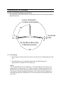
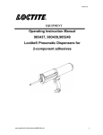
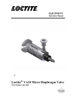
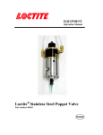
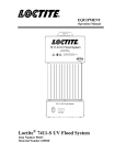
7700
Loctite® Handheld LED Light Sources
Part Number 98591 Model 7700 Light Source
Part Number 98595 Model 7703 Light Source
Label # 988830
EQUIPMENT
Operation Manual
TABLE OF CONTENTS
1. PLEASE OBSERVE THE FOLLOWING .................................................................................................. 3
1.1
1.2
1.3
1.4
EMPHASIZED SECTIONS ............................................................................................................................ 3
ITEMS SUPPLIED ....................................................................................................................................... 3
FOR YOUR SAFETY .................................................................................................................................. 3
FIELD OF APPLICATION, (INTENDED USAGE)............................................................................................ 4
2. DESCRIPTION .............................................................................................................................................. 4
2.1
2.2
THEORY OF OPERATION ........................................................................................................................... 4
OPERATING ELEMENTS AND CONNECTIONS, REFERS TO FIGURE 1 ........................................................... 5
3. TECHNICAL DATA....................................................................................................................................... 6
3.1 ENERGY REQUIREMENTS .......................................................................................................................... 6
3.2 DIMENSIONS............................................................................................................................................. 6
3.3 UV OUTPUT CHARACTERISTICS ............................................................................................................... 6
4. OPERATING THE UNIT............................................................................................................................... 6
4.1 CHARGING THE UNIT ................................................................................................................................ 6
4.2 RECOMMENDED INSTALLATION AND OPERATION .................................................................................... 7
4.3 POWERING UP .......................................................................................................................................... 7
4.4 ON/OFF SWITCH WARNING – LOW BATTERY, HIGH TEMPERATURE ........................................................ 8
4.5 CHECKING THE UNIT’S OUTPUT ............................................................................................................... 8
4.6 USING FOOT SWITCH ............................................................................................................................... 9
4.7 REPLACING BATTERIES ............................................................................................................................ 9
5. CARE AND MAINTENANCE ..................................................................................................................... 9
6. TROUBLESHOOTING ................................................................................................................................ 10
7. DOCUMENTATION .................................................................................................................................. 10
7.1
REPLACEMENT PARTS AND ACCESSORIES .............................................................................................. 10
1.
1.1
Please Observe the Following
Emphasized Sections
WARNING!
Refers to safety regulations and required measures that protect the operator or other
persons from injury or danger to life.
Caution!
Emphasizes what must be done or avoided so that the unit or other property is not
damaged.
Notice:
Gives recommendations for better handling of the unit during operation or adjustment,
as well as for service activities.
1.2
Items Supplied
1 Loctite® Handheld LED Light Source
1 AC Adapter/Charger
1 User’s manual
1.3
For Your Safety
For safe and successful operation of the unit, read these instructions completely. If the
instructions are not observed, the manufacturer can assume no responsibility. Be sure
to retain this manual for future reference.
WARNING!
While the Loctite® Handheld LED Light Source has minimal output in the UV-A
range, the use of UV safety glasses that conform to ANSI Z87.1/CSA Z94.3 is
recommended when operating the unit.
WARNING!
Never directly expose skin to light source.
WARNING!
Never look into the end of the light source.
WARNING!
Damage to the AC Adapter/Charger power cord can result in contact with live electrical
parts. Check the power cord before each use. If the power cord is damaged, do not
operate.
The unit may be repaired only by a Loctite authorized service technician.
Caution!
This unit will heat up under certain operating conditions. The unit should not be
left on continuously. Avoid operating the unit at duty cycles greater than 30% with on
times of 15 seconds or greater. Longer exposure times are possible if the unit off time
is increased to allow the unit to cool in between exposures. The unit has an internal
mechanism that shuts it off if a preset internal temperature is reached during operation.
1.4
Field of Application, (Intended Usage)
This Loctite® Handheld LED Light Source is designed for use with light cure
products that cure when exposed to ultraviolet and/or visible light. The system can be
operated manually or controlled with an external switch. The system is design for
intermittent duty cycle.
2.
Description
2.1
Theory of Operation
The Loctite® Handheld LED Light Source utilizes a focused LED light source. The
unit can be powered by its internal rechargeable batteries or directly from the AC
Adapter/Charger, 989626. When the unit is switched on, the proper electrical power
is supplied to the LED resulting in immediate full power. Curing will take place when
the light is directed at the liquid adhesive. The time required to complete the curing
process depends primarily on the offset distance from the end of the wand to the
surface of the adhesive and the type of adhesive being used.
The exposure time can be controlled in either the manual mode or through the use of
an external switch. The unit can be run from the rechargeable batteries or directly
from AC power via the AC Adapter/Charger.
The unit should not be left on continuously. Avoid operating the unit at duty cycles
greater than 30% with on times of 15 seconds or greater. Longer exposure times are
possible if the unit off time is increased to allow the unit to cool in between
exposures. The unit has an internal mechanism that shuts it off if preset internal
temperature is reached during operation. Should this occur, the unit would not operate
until the unit has cooled below this thermal limit.
The Loctite® Handheld LED Light Source can also be actuated by a remote foot
switch, P/N 98440.
2.
Description (continued)
2.2
Operating Elements and Connections, refers to Figure 1
1. Power Inlet Module
Connect AC Adapter/Charger to power inlet module.
2. On/Off Switch
Depressing the On/off Switch causes light to be irradiated from the unit.
3.
External Switch Connection
The Loctite® Handheld LED Light Source can also be actuated by an external
foot switch, Loctite® P/N 98440.
4. Low Power/Thermal Limit Indicator
When illuminated a red light will be visible by the on/off switch. This indicates
that the battery charge has dropped below the charge needed to maintain
acceptable output or that the unit has exceeded a pre-set internal operating
temperature. The unit can be used while it is charging, however, it will take
longer to reach its full charge. If the unit has exceeded its operating temperature,
the unit should be allowed to cool prior to additional use.
2
7700
Label # 988830
1
3
4
Figure 1
3. Technical Data
3.1 Energy Requirements
Input Power:
100-240 VAC, 47-63 Hz
3.2 Dimensions
Width
1.0 inch
Depth:
0.75 inches
Height:
9.0 inches
Weight: 0.44 pounds
3.3 UV Output Characteristics
Typical Output *:
Spectral Output Range:
Primary Peak:
7700 Units
1.0 W/cm2
390 – 420 nm
405 nm
7703 Units
>3 W/cm2
Proprietary
Proprietary
(*Exact output measurement is dependent on the brand and calibration method of the meter
used. These measurements were made with the Loctite® Zeta® 7011-V Dosimeter, P/N
98089 and 98453 Adapter.)
Note: For intensity measurements of LED devices emitting at the 405 nm wavelength, the
Zeta 7011-V meter can be used to determine LED degradation. However, because the 405
nm wavelength is just outside the optimal absorbency range of the Zeta 7011-V, the reading
could be lower than it actually is. Also, intensity readings from meter to meter may vary.
That is to say, if two meters are used to measure the same LED device, the readings could be
different. As long as the same meter is always used to measure the same 405 LED device, the
Zeta 7011-V can be used to measure intensity degradation.
4. Operating the Unit
4.1 Charging the Unit
Caution!
Be sure to charge the batteries for 12 hours prior to using the unit. Failure to completely
charge the batteries may result in limited operation time before charging is required. Use
only Loctite® Charger P/N 989626, to charge the unit. No other chargers will work and
will damage the unit.
4. Operating the Unit (continued)
4.2 Recommended Installation and Operation
When operating in a hand held mode or permanently mounted, the following orientation
should be observed.
Correct Orientation
To Mount and Operate
90°
5°
Horizontal
Line
5°
Do Not Mount More Than
5° Below Horizontal
170°
4.3
Powering Up
1. Depressing the on/off switch on the unit causes the unit to emit light from the wand
tip.
2. When the batteries are completely charged, the unit should operate for
approximately 45 minutes at a 30% duty cycle.
Notice:
The unit should not be left on continuously. Avoid operating the unit at duty cycles
greater than 30% with on times of 15 seconds or greater. Longer exposure times are
possible if the unit off time between exposures is increased to allow the unit to cool.
The unit has an internal mechanism that shuts it off if a preset internal temperature is
reached during operation. Should this occur, the unit would not operate until the unit
has cooled.
4. Operating the Unit (continued)
4.4
ON/Off Switch Warning – Low battery, High Temperature
A red indicator light will come on next to the on/off switch if the battery voltage gets
too low or if the unit gets too hot for optimum operation. To determine which
condition the warning is due to, connect the charger to the unit. The red light should
shut off if the batteries are low when you actuate the on/off switch and you can
continue to operate with the charger connected or allow the unit to charge for 12 hrs
before using the unit without the charger connected.
If the red indicator light continues to illuminate once the charger has been connected
and you depress the on/off switch, then the indicator light has come on because the
optimum operating temperature of the unit has been exceeded. The unit will operate
once it has sufficiently cooled below a pre-set limit.
Tips for cool operation:
1)
Avoid operating the unit in a high heat area or near heat sources.
2)
Place the unit on a cool surface in between cure cycles.
3)
Place the unit in front of a fan in between cure cycles.
4)
Mount the unit to a stand and direct air from a fan toward the unit.
5)
Alternate using two units. When one reaches the temperature limit, place on a
cooling surface and begin curing with the second unit. Alternate as needed
during operation.
6)
For mounted applications, a heat sink can be clamped to the unit to help
dissipate heat.
If your application demands curing cycles that cause the unit to reach the thermal
limit consistently, contact Henkel Corporation at 860-571-5209 for alternative
solutions for cooling the unit.
4.5
Checking the Unit’s Output
To check the unit’s output, insert the LED tip directly into the UVV meter adapter
98453. Hold the LED unit perpendicular and flush against the adapter plate. Irradiate
the sensor for 5 seconds to check the system output.
4. Operating the Unit (continued)
4.6
Using Foot Switch
The Loctite® Handheld LED Light Source can also be actuated using a foot switch,
P/N 98440. By depressing the foot switch, the light will turn on. Once the foot
switch is released the light will turn off.
4.7
Replacing Batteries
After extended use, the rechargeable batteries may experience a diminished capacity
for holding a charge. If the batteries need to be replaced, please contact Henkel
Equipment Service Group at (800) 562-8483.
5.
Care and Maintenance
Notice:
It is recommended that the light output from the light source be monitored regularly
using a Loctite® Zeta® 7011-V radiometer, P/N 98089.
Caution!
It is recommended that the end of the light source be positioned no closer than 0.25”
inch from the Loctite® product being cured to minimize adhesive contamination on
the light source tip. If adhesive should contaminate the light source tip, be sure to
clean the light source tip to maximize the unit’s effective output.
Notice:
Vapors from some products may gradually accumulate on the end of the light source,
reducing the light output. It should be inspected regularly and cleaned as necessary
using isopropyl alcohol and a soft, clean cloth.
6. Troubleshooting
Type of Malfunction
Possible Cause
No light is irradiated from unit when
on/off switch is depressed.
No light is irradiated from unit when
on/off switch is depressed. Red light
is seen around circumference of on/off
switch.
All system functions appear to be
operating, but the product does
not cure completely, or if a radiometer
is used to monitor the UV output, the
power is low.
- Batteries are not charged.
- Unit has exceeded thermal operating limit.
- Defective Switch.
- Batteries have too little charge to power unit.
Correction
• Plug unit into AC
Adapter/Charger. Charge Batteries.
• Allow unit to cool
• Call 800-562-8483.
• Plug unit into AC
Adapter/Charger. Charge batteries.
- Unit has exceeded thermal operating limit
• Allow unit to cool
- End of light guide has an accumulation of
product or other contaminants
• Clean light guide with soft cloth
and isopropyl alcohol.
7.
Documentation
7.1
Replacement Parts and Accessories
Loctite Part Number
Description
98452
Safety Glasses
98089
98453
98440
Loctite® Zeta ® 7011-V Dosimeter-Radiometer
Dosimeter Adapter Kit
Foot Switch
98592
Remote mount heat sink and continuous duty power supply
960356
Timer
988774
Constant on plug
989626
Universal AC Adapter/Charger
8900494
LED Replacement Battery Kit
EQUIPMENT WARRANTY
For Loctite® Handheld LED Light Source
Henkel Corporation warrants, to the original purchaser for a period of 1 year from date of delivery, that
the Loctite® Handheld LED Light Source sold by it is free from defects in material and workmanship.
Henkel will, at its option, replace or repair said defective parts.
This warranty is subject to he following exceptions and limitations.
1.
Purchaser Responsibilities – The Purchaser shall be responsible for:
-Normal maintenance and minor adjustments of the equipment as outlined in the Equipment
Manual.
-Notification to Henkel of the need for warranty service.
-Any cost of travel or transportation connected with warranty repair.
-All cost associated with investigating or correcting any failure caused by the purchaser’s misuse,
neglect or unauthorized alteration or repair.
-All costs attributed to accident or other factors beyond Henkel’s control.
2.
No warranty is extended to perishable items, such as:
-Fuses
3.
-Switches
-Batteries
The purchaser must provide proof of purchase (original sales receipt, includes price paid, date of
purchase).
No warranty is extended to any equipment, which had been altered, misused, neglected or damaged by
accident.
Henkel reserves the right to make changes in design and/or improvements to its equipment without
obligation to include these changes in any equipment previously manufactured. Correction of defects by
repair or replacement shall constitute fulfillment of all warranty obligations on the part of Henkel
Corporation.
THIS WARRANTY IS IN LIEU OF ALL OTHER WARRANTIES, EXPRESSED OR IMPLIED, INCLUDING
WARRANTIES OF MERCHANTABILITY OR FITNESS FOR A PARTICULAR PURPOSE, AND IS THE SOLE
AND EXCLUSIVE REMEDY FOR ANY CLAIM OF DAMAGES ARISING FROM ANY DEFECT IN THE
LOCTITE EQUIPMENT. HENKEL SHALL HAVE NO LIABILITY FOR CONSEQUENTIAL DAMAGES OR
PERSONAL INJURY, OR FOR LOSS, DAMAGE, OR EXPENSE, DIRECTLY OR INDIRECTLY ARISING
FROM THE USE OF ITS PRODUCTS. NO AGENT, DISTRIBUTOR OR OTHER PARTY IS AUTHORIZED TO
MAKE ANY WARRANTY ON BEHALF OF HENKEL, OR TO ASSUME FOR THE HENKEL CORPORATION
ANY OTHER LIABILITY WITH RESPECT TO ITS PRODUCTS.
Henkel Corporation
1001 Trout Brook Crossing
Rocky Hill, CT 06067-3910
Henkel Canada Corporation
2225 Meadowpine Boulevard
Mississauga, Ontario L5N 7P2
Henkel Automotive
Technology Center
2455 Featherstone Road
Auburn Hills, Michigan 48326
Henkel Ltda.
Rua Karl Huller, 136 – Jd.
Canhema 09941-410
Diadema/SP, Brazil
Henkel Capital, S.A. de C.V.
Calzada de la Viga s/n Fracc. Los Laureles
Loc. Tulpetlac, C.P. 55090
Ecatepac de Morelos, Edo. de México
www.loctite.com
Loctite is a trademark of Henkel Corporation, U.S.A. © Copyright 2006. Henkel Corporation
All rights reserved. Data in this operation manual is subject to change without notice.
Manual P/N: 989612, Rev G, 07/2007