1
Cloud Sensor User’s Manual
2006-01-19
Serial # __________
Distributed by:
Diffraction Limited
http://www.cyanogen.com
Phone: (613) 225-2732
Manufactured by:
Boltwood Systems Corporation
Copyright 2004, 2005, & 2006 Boltwood Systems Corporation
V004G for firmware version 0x35 and above, and Clarity version 1.58 and above.
Cloud Sensor User’s Manual
TABLE OF CONTENTS
1. Warnings ..............................................................................................................................2
2. Introduction ..........................................................................................................................3
3. Operating Principles ..............................................................................................................3
4. Software Installation and Cloud Sensor Familiarization ...........................................................5
5. Cloud Sensor Unit Installation................................................................................................7
6. Reliability .............................................................................................................................9
7. Birds...................................................................................................................................12
8. Lightning............................................................................................................................12
9. Clarity Software..................................................................................................................13
10. Remote Operation..............................................................................................................17
11. Contact Closure For Emergency Observatory Shutdown ......................................................19
12. Error Messages..................................................................................................................19
13. COM Interfacing ...............................................................................................................20
14. Warranty...........................................................................................................................21
15. Contacting Us....................................................................................................................22
1. Warnings
a) THIS DEVICE IS PRIMARILY INTENDED FOR OBSERVATION PLANNING. While it
can be used to trigger the closure of an observatory under adverse weather conditions, it is
NOT intended as the primary or sole protection against rain or snow entering the
observatory. Under certain meteorological conditions it is possible for rain to occur without
clouds being detected by the sensor. Significant rainfall or snowfall may occur before the
wetness detector triggers. Improper installation or adjustment may impair detection of
adverse weather conditions. Operator vigilance and the use of multiple weather
information sources are essential when operating an observatory remotely.
b) THE METAL SENSOR HEAD AT THE TOP END OF THE CLOUD SENSOR UNIT
CAN GET HOT (70°C or 158°F). Do not touch it carelessly even if you think that it should not
be hot. An unlikely failure of the wetness sensor could cause it to heat unexpectedly.
c) The emergency dome closure connector (see section 11) may call for a dome closure at any time.
IF YOU ARE WORKING ON THE DOME, TURN OFF THE POWER TO THE DOME.
d) Please do not adjust the 7 screws around the outside of the cloud sensor unit . On some versions
of the Cloud Sensor they are supposed to stick out a bit.
e) When correctly installed, the Cloud Sensor Unit is rain -proof. Never immerse the unit in water.
Also, the power supply and adaptor box are for indoor use only.
f) At the cable connector end of the Cloud Sensor Unit there is a small temperature sensor. It is
fairly well protected from mechanical damage but, if you really try, you could break it.
g) The mini-DIN connector on one end of the cable can be plugged into your PC and other devices.
Do not do that. It is ONLY to be plugged into the supplied adaptor box.
h) We strongly suggest that you try the Cloud Sensor Unit indoors as explained in section 4 before
doing the final installation.
V004G
2
Cloud Sensor User’s Manual
2. Introduction
The Cloud Sensor senses how clear the sky is, measures the ambient air temperature, and detects wetness
(snow and rain). It must be mounted out of doors in a location that provides a clear view of the sky. A
cable runs from the sensor unit to the indoors, and connects to the supplied adaptor box. This adaptor box
has a wall plug power supply connector, a DB-9 serial port for connection to a computer, and another
connector which is used to request an emergency dome closure. The supplied “Clarity” software operates
with Windows 98 and later, and provides a visible and audible interface. It has a single line file and a
COM (ActiveX) interface to allow the Cloud Sensor to input to observatory automation software.
Here are some of the intended uses of the Cloud Sensor and Clarity software:
a.
b.
c.
d.
e.
f.
g.
Identify sky conditions before starting an observing session or opening a remote observatory;
Warn the user who is indoors, when the skies become clear so the user knows that observing
could start or resume;
Warn the user that conditions have changed from clear to cloudy and that further imaging will
not succeed;
Warn the user that conditions have become very cloudy and that the observatory should be
closed soon;
Warn the user that conditions have become wet and the observatory should be closed
immediately;
Automatically close an observatory when conditions become very cloudy or wet, even if the
user is not at the computer to see the warning, or the computer is not functioning;
Provide the Cloud Sensor’s data via a COM (ActiveX) or file interface, to other software.
3. Operating Principles
The Cloud Sensor detects the presence of clouds in an indirect manner. What it really does is measure the
sky temperature by sensing the infrared radiation from the sky in the 8 to 14 micron wavelength range. It
uses a thermopile to do this. It then compares this reading to the ambient temperature at the bottom of the
Cloud Sensor Unit. A clear sky is at least 20°C (36°F) colder than the ambient temperature near the
ground. A fully overcast sky with low clouds (the kind that rain usually comes from) usually will be
close to the same temperature as the ambient temperature.
Very high thin clouds composed of ice crystals (cirrus) are by nature quite cold and therefore may not be
detected by the Cloud Sensor. Unfortunately, this might fool you into thinking that you can observe when
you cannot. This might waste a bit of your time but on the positive side these clouds do not contain rain.
There are some unusual meteorological situations where rain clouds can be high above ground and
therefore cold. If so there will be a warning only after the rain begins to fall.
While these limitations due to the physics of the atmosphere are unfortunate, you should find the Cloud
Sensor a very useful adjunct to your astronomic al observing, just as we do.
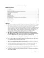
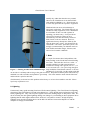
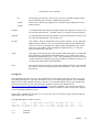
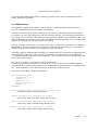
The thermopile for measuring sky temperature is inside the little round can (a TO-5 transistor case
actually) on the sky end of the Cloud Sensor Unit. You can see the filter aperture that lets the infrared
radiation enter the device. This device also contains a thermistor which is used to measure the
temperature of the case around the thermopile. At the other end of the Cloud Sensor Unit, near the cable
connector, is a thermistor which measures the ambient temperature. The Cloud Sensor Unit should be
V004G
3
Cloud Sensor User’s Manual
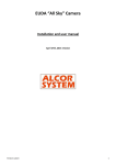
Sky End View (shows the sensor head)
Outer plastic tube sun shield
Thermopile
Wetness sensor’s grounded plate
Filter aperture for infrared radiation
Wetness sensor’s sensitive plate
Ground End View
Outer plastic tube sun shield
Serial number
Ambient temperature sensor
Model and manufacturer
Inner plastic tube
Connector for cable
Note that the 7 screws which support the inner plastic tube and lock the circuit board in place
have been omitted for clarity.
Figure 1 - Ends of the Cloud Sensor Unit
positioned so that this ambient-measuring thermistor will actually be at a temperature near that of the
ambient ground temperature.
Around the thermopile device there are two concentric stainless steel disks, the top one being a little
smaller than the one beneath. These two disks are electrically insulated from each other and together they
form the wetness detector. If a drop of water bridges the two disks, a slight electric current flows between
them signaling the presence of moisture. This sensor is also able to detect snow and ice because usually it
is heated sufficiently to melt them.
The thermopile cannot see through any form of water. This means that any wetness must be removed
quickly. This is done by three methods. First, the sky end of the Cloud Sensor Unit is normally heated to
4°C (7°F) or more above the ambient temperature to prevent the formation dew or frost. Second, when it
V004G
4
Cloud Sensor User’s Manual
is wet, the sensor head is heated to 70°C (158°F) until it is dry. Third, the Cloud Sensor Unit is installed
at a tilt from the vertical position so water runs off of the sensor head.
The double tube configuration provides a solar shield for the sensor unit – especially for the ambient
thermistor. The Cloud Sensor is primarily designed for use just before and during the night. It is not well
enough shielded to give fully accurate ambient temperature readings in full sun, especially if mounted
over a hot roof rather than on a pole over vegetation.
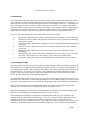
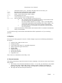
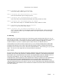
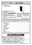
Sky end
Cloud Sensor Unit
Cable
Adaptor box
oxox
Power
Supply
To a PC
serial
port
Emergency
dome close
connector
Figure 2 – Cloud Sensor system with the hardware parts interconnected
4. Software Installation and Cloud Sensor Familiarization
The CDROM supplied contains the Clarity software, this manual, and the program TestClarity.
TestClarity is discussed in section 13.
V004G
5
Cloud Sensor User’s Manual
Please follow these steps to install the software and test the Cloud Sensor:
1.
Install the Clarity software from the supplied CDROM, or from a more recent version you have
found on the web site. When you insert the CDROM into your computer, the install program
should start automatically. Just follow its on-screen instructions. If it does not start automatically,
please browse the contents of the CDROM and run the program called “SetupClarity.exe”.
You might wish to add the Clarity program to your startup menu so that Clarity is always running
when your computer is running.
2.
Next, try the system indoors before installing the Cloud Sensor Unit outdoors, by following these
steps:
a. Do not plug in the wall plug power supply yet. This precaution is necessary in case you
misregister the rectangular connector at the rear of the Cloud Sensor Unit. Connect the cable to
both the Cloud Sensor Unit and to the adaptor box. The cable is supplied in a coil held together
with white cable ties. Enough slack has been left at each end so that you probably do not need
to cut the ties.
b. Connect the adaptor box to one of the computer’s serial ports using the supplied DB9 extension
cable. Note which COM port number you have used. Check that the line voltage marked on
the power supply matches your line voltage. Then plug in the power supply to the adaptor box
and to the building power. The “audio” jack on the adaptor box is not used at this time. If the
Cloud Sensor Unit is not yet near room temperature, leave it until it is. It does not matter in
what order you plug things together or run the software, except as concerns the registration of
connectors noted above.
c. Run the Clarity software. You may get the message, “Could not find any previous settings in
registry - using defaults. This is normal if Clarity has never been run before”. Just click OK.
d. Enter your COM port number into the “COM Port” field. If all is well, after less than 30
seconds the circle just to the left of the COM port field will flash green every 3 seconds
meaning that the computer is receiving signals from the Cloud Sensor Unit. If the circle
remains red or you get “No Msg’s” continuously, check all of the Cloud Sensor hardware
connections and make sure that you have the COM port number correct.
e. Familiarize yourself with the software, and the various readings and alerts. After a few
seconds, the three fields at the top of the window should contain numbers. Aim the unit at
something that is at room temperature and the left hand number should be near zero. If it reads
999.9, wait a couple of minutes for the sensor to heat up a bit and try again. Aim it at your skin
and the number should read either a few degrees positive or 999.9 (it won’t show your true
temperature because it quickly saturates for positive temperatures, indicating 999.9). Aim it at
something taken from your freezer and the number should be quite negative.
During all of this, the top middle number field should be showing the air temperature in the
room. The “% heat” box should be above zero all of the time (indicating that heat is being
applied to the sensor’s case) dropping to a low (but non-zero) value when the sensor’s case has
been warmed to about 4°C (7°F) above the ambient temperature.
V004G
6
Cloud Sensor User’s Manual
After a few minutes the top right number field should indicate a temperature that is about 4°C
(7°F) above the Ambient Temp. If this is true, slightly dampen your finger and touch across the
sky end stainless steel disks (CARE – an unlikely fault could cause these to be hot). The
junction between them is the rain sensor. By bridging it you are simula ting rain. The “wet”
square should turn blue and the stainless steel disks should get warm to the touch in a minute or
so. If you wish to, you can simulate some “rain” with a sprinkle of water. The sensor head
should then heat until the water on the junction between the stainless steel disks evaporates.
The heater will then shut off until the sensor head cools. NOTE that the sensor head could heat
up to a HOT 70°C (158°F).
Take a look at section 9.1 of this manual and try out the Alert For and Alert Type check boxes,
and the Clear/Cloudy/Very Cloudy (V.C.) thresholds. Become familiar with the various alerts.
5. Cloud Sensor Unit Installation
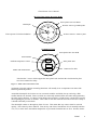
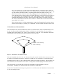
The Cloud Sensor Unit must be installed out of doors in a location where it has an unobstructed view of
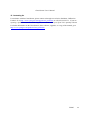
the sky. It will not work through a glass window. Its field of view is in the shape of a cone with an
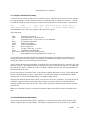
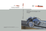
included angle of approximately 80°. There is some sensitivity out to 120°. Any substantial obstruction
in that field of view will reduce the sensitivity and accuracy of the unit.
Some sensitivity
Main sensitivity
Figure 3 - Cloud Sensor sky angular coverage
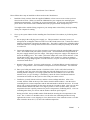
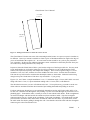
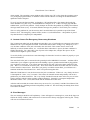
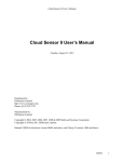
The unit is installed with a tilt of 10°, or a bit more, from the vertical. This tilt allows water to run off of
the surface of the stainless steel disks. Otherwise it would take a lot of heating to evaporate that water.
It would be better to lean 10° into the direction from which the prevailing win ds blow. This will allow, in
most situations, the Cloud Sensor Unit to detect a change in the weather slightly earlier than otherwise.
The Cloud Sensor is quite robust but it must not be installed in a highly polluted or corrosive
environment. Normally you would not locate an observatory in such a place.
Because the Cloud Sensor head can get very hot (70°C or 158°F), locate the Cloud Sensor Unit such that
no one can casually touch it.
V004G
7
Cloud Sensor User’s Manual
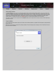
>3.3 cm
(>1.3”)
19 cm
(7.5”)
Figure 4 - Tilting Cloud Sensor to allow the rain to run off
The Cloud Sensor Unit does not come with a mounting bracket because we expect everyone’s situation to
be different. One way to mount it would be to fasten a piece of aluminum channel or angle to the edge of
your roof and tilted at the requisite 10°. An even better location would be on a pole or post positioned
over vegetation. In this way the ambient temperature sensor would not be affected by the heat from your
roof or driveway during and after a hot, sunny day.
Prepare to fasten the Cloud Sensor Unit to your bracket using two of the longer cable ties. You may need
to put small notches in your bracket where the ties will go around it so as to avoid having the Cloud
Sensor Unit slip down (especially with temperature changes). Place each tie against a ring of 3 screws
around the 6 cm (2.4”) tube, with the ties on the middle side of the screws. Position the Cloud Sensor
Unit near the top of the bracket such that the thermopile cannot see the bracket. Make the bracket long
enough to keep the Cloud Sensor Unit above any snow drifts – if you get any.
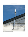
Figures 5, 6, and 7 show a sample installation. 2 cm ( ¾”) aluminum angle 1.5 mm (.060”) thick was used
along with some 2.5 cm (1”) square aluminum tubing with a 1.3 mm (.050”) wall thickness.
The cable has been sent to you in a coil without twists in it. To keep it that way you need to cut the two
white cable ties and then unroll the cable instead of just holding the bundle and pulling at one end.
For those who do not already have a convenient hole through an exterior wall for the cable, drill a 15 or
16 mm (5/8”) diameter hole through the wall, making very sure not to drill through any electrical wires or
plumbing pipes. To thread the cable, it usually is easier to start with the cable inside. Push a straightened
out metal coat hanger with the hook at the outside end, from outside to inside. Tape the rectangular
connector and 10 cm (4”) of cable to the coat hanger. Pull on the coat hanger. You might need a second
person inside to unroll the cable and to make sure that the cable does not snarl. If you are alone, unroll
the cable inside first before pulling it through the wall. Note that the end of the cable with the rectangular
connector goes to the Cloud Sensor Unit.
V004G
8
Cloud Sensor User’s Manual
If you must use a smaller hole (large enough for the cable itself but without the connector), you can
disassemble the rectangular connector using a very small screwdriver and a lot of care. First push the 5
wires into the connector slightly. This disengages the retaining tabs on the clips. Then you depress the
retaining tab of the clip for each pin. They are visible in each of the rectangular small holes on the longer
side. With the retaining tab depressed you gently pull on the wire and the clip will come out.
Before reassembling the connector you might need to use a small knife to bend each retaining tab upward
slightly. The pinout for the rectangular connector is:
Pin Number
1
2
3
4
5
Wire
black
white
red
green
brown
Signal
Data Out
Data Return
+9V Return
+9V
/ITSWET
Note that the “1” (for pin 1) molded into the rectangular connector housing is hard to see. It is right
beside one of the side slots at the edge of the connector. Pin 5 has “2695” molded in over it.
Another possibility for those with some electronic assembly skills, is to cut the cable at a point that will
be well indoors when you are finished. Then thread the outdoor portion though the wall. Now cut back
the covering on both sides of the cut. Slip large heat shrink tubing over one end of the cable. Strip the
wires and slip heat shrink over each wire on one side. Solder the wires together matching the colors.
Insulate the joints with the heat shrink and shrink it. Slip the large heat shrink over the entire joint and
shrink it.
Do not have the wall plug power supply plugged in when doing the next step. This precaution is
necessary in case you accidentally misregister the rectangular connector at the rear of the Cloud Sensor
Unit. Plug the rectangular connector on the cable into the bottom end of the Cloud Sensor Unit. Use one
of the cable ties to strain-relieve the cable on something below and close to the unit. Tie the cable against
a flat or convex surface - not the inside of an angle or U channel.
Fasten the cable to the building using the cable ties that are supplied. The ties that have a hole at the end
allow you to screw them to a wall. If you need extra ties you should be able to find them in the electrical
section of a hardware store. Use the black version (which should be labeled UV light resistant).
Support the cable well enough so that it will not flex in the wind – especially if the temperatures might go
below -20°C (-4°F). The cable is inflexible when very cold and may crack if flexed or handled. Put a
drip loop into the cable before entering the building so that water running down the cable cannot run into
the hole in the wall.
Bring the cable indoors to near your computer. Plug the Cloud Sensor cable into the adaptor box and you
are done.
6. Reliability
The Cloud Sensor is built to good commercial standards and failures should be very rare. It should give
satisfactory service for many years. Its most essential detector as far as observatory safety is concerned,
is the wetness detector. If it does give an erroneous reading, it is more likely to show wetness when it is
V004G
9
Cloud Sensor User’s Manual
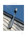
Figure 5 - Typical roof installation (note the tilt)
V004G
10
Cloud Sensor User’s Manual
Figure 6 - Showing the aluminum square tubing that allows the aluminum angle to clear the roof edge
V004G
11
Cloud Sensor User’s Manual
actually dry, rather than the other way around.
However the Cloud Sensor is not ultra-reliable
with multiple redundancy, etc. Please do not use
it as the only protection for expensive equipment.
Wind and rain can cause serious damage to
observatory equipment. The Cloud Sensor is not
intended as safety equipment, nor is it intended to
be a substitute for due care and vigilance in
operating your observatory. It can provide an
extra level of security by being set up to
automatically close the observatory whenever
thick clouds or rain are detected. However,
significant rain may already have fallen by the
time the observatory closes – this should only be
considered a “last resort” protection system. We
strongly recommend that you maintain watch on
local satellite and radar images, forecasts, and
observe local weather conditions.
7. Birds
A couple of customers have had problems with
birds perching on the Cloud Sensor thus blocking
the sensor. The birds also used it as a toilet. A
possible solution is to find some galvanized
welded wire fencing with a grid of 1/2" to 1" (1.5
to 2.5 cm) mesh size. Cut a piece long enough to
Figure 7 - Showing notches in the aluminum angle wrap around the Cloud Sensor (about 8" or 20 cm)
and about 2" (5 cm) wide. Do the cutting such that
on one side it is all sharp ends as long as the grid size allows. Wrap this around the plastic tube at the top
and hold it on with a stainless steel plumber's gear clamp. This won't interfere much with the IR sensor
and should be a pain for the birds.
(Un)fortunately we do not have this problem at the factory so we have been unable to test this. Please
report any experiences to us.
8. Lightning
Unfortunately many good mounting locations will also attract lightning. The Cloud Sensor has lightning
protection in the Cloud Sensor Unit and in the adaptor box. These should protect against the surge from
nearby lightning hits. They will not protect against a direct hit (nothing simple or inexpensive will). We
do not warranty the unit against lightning damage, nor damage to your building or other equipment due to
lightning that the cable might conduct inside, because it is beyond our control. In high frequency
lightning areas an optical isolation device on the RS-232 interface between the adaptor box and the
computer is strongly recommended.
V004G
12
Cloud Sensor User’s Manual
If the unit is vulnerable, place a properly grounded lightning rod nearby. Also provide a heavy grounding
wire from the metal bracket you mount the unit on directly down to a ground rod. The typical roof
installation pictured in figures 5 and 6 has such a grounding wire. A few loops in the cable near to the
cable entrance to the building will also help keep a direct stroke of lightning out of the building.
9. Clarity Software
This software package runs on your Windows PC and interprets the measurements from the Cloud Sensor
Unit. It also allows you to control which events will cause alerts and what those alerts will be. It is
named “Clarity” because it indirectly displays the clarity of the sky above the sensor. The following is a
field by field description of the window:
9.1 Window
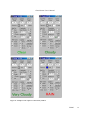
The caption of the Clarity window gives the version number of the Clarity software. The Clarity window
shows the latest data from the Cloud Sensor Unit on the top row. Below that is a square that contain a
flag which changes color if the Cloud Sensor Unit is wet (blue), or shows the same color as the window
background. To the right is the heater power as a percentage.
The Clarity window displays temperatures in either degrees Celsius (°C) or degrees Fahrenheit (°F). The
choice is yours, and you set it using the °C and °F buttons. Some fields display actual temperature. In the
top left hand example in figure 8, Ambient Temp. is 25.1°C. Other fields contain temperature
differences. In the same example, Sky-Amb. Temp. is –31.4°C.
The other fields are operator settable and control how the Cloud Sensor data is used. Some combinations
which would not make sense are prohibited. Some seemingly unusual ones do make sense, such as
alerting for clear, very cloudy and wet. You might wish to make such a selection when your observatory
is open but some clouds came in preventing observing, and you expect they will disappear soon.
In detail:
Sky-Amb. Temp.
Sky temperature minus ambient temperature. This is near zero for a fully
overcast sky and, say, –25°C (-45°F) or more negative for a clear sky.
Note that this value may be quite erratic when the sensor is wet. This occurs
because of a varying amount of water over the thermopile window, and effects
from the operation of the heater while it tries to evaporate off the water.
This might saturate to 999.9 if the unit is pointed at something that is warmer
than ambient. It might saturate in the other direction to –999.9 when it is pointed
at something that is very cold relative to the thermopile case. Some thermopiles
will saturate at –60°C. If this happens, be thankful that you have such skies!
Ambient Temp.
Ambient temperature (from the sensor located at the bottom end of the Cloud
Sensor Unit). This serves as an approximation for the near ground temperature.
Sensor Temp.
Temperature of the case of the thermopile.
V004G
13
Cloud Sensor User’s Manual
Sensor Is:
wet
% heat
When this is blue, it is raining (snowing) or has just finished raining (snowing).
This condition is also possible under extreme dewing or frosting conditions.
This shows how much of the available heater power is being applied to the sensor
head.
Thresholds:
Clear/Cloudy
Cloudy/V.C.
User settable. When the Sky-Amb. temperature is more negative than this value,
Clarity declares the sky to be "clear". When it is more positive than this, the sky
is "cloudy". The default value is -25°C (-45°F). As you gain experience with
using Clarity you may wish to adjust this number to better suit loc al conditions
and the current season.
User settable. V.C. stands for “Very Cloudy”. When the Sky-Amb. temperature
is more negative than this value, Clarity declares the sky to be "cloudy" (or
“clear” – see above). When it is more positive than this, the sky is "very
cloudy". The default value is -10°C (-18°F). As you gain experience with using
Clarity you may wish to adjust this number to better suit local conditions and the
current season. Very cloudy skies are the kind which can quickly degrade into
raining skies, and there is no point in trying to observe when it is that cloudy.
Alert For (user settable):
Clear
Alerts if the Sky-Amb. Temp. is more negative than the Clear/Cloudy Temp.
Cloudy
Alerts if the Sky-Amb. Temp. is more posit ive than the Clear/Cloudy Temp.
V.Cloudy
Alerts if the Sky-Amb. Temp. is more positive than the Cloudy/V.C. Temp.
Wet
Alerts when it is raining or snowing.
Alert Type (user settable):
Visual
The bottom field in the window shows the current weather status, normally
colored green. If this box is checked and there is an alert, the text will be shown
as light green, pink or red depending upon the importance, and it will flash.
Beeper
Your computer’s built in speaker is used for alerts. Three different sounds are
used. The first is for a normal alert. A stronger sound is used if it is very cloudy.
An even stronger alert is given if it is raining. Note that Windows 98 uses the
“System Beep” which will not differ between alert types, and on some computers
might be barely audible.
Sound
Your computer’s sound card is used to generate the alerts. A rain alert is
emphatic.
COM Port
User settable. This allows you to inform Clarity as to which serial port the Cloud
Sensor is connected to. The small circle to the left of the number should color
every 3 seconds. This means that a message has arrived from the Cloud Sensor.
Logging:
User settable. Clarity can create a log file in your computer and record the
information from the Cloud Sensor Unit. The log file is located where you
choose (Log File button explained below) and new data is appended to it as
requested below. The file is normally kept closed so you can view it with an
editor while Clarity is running. The user may set:
The log file is not to be used.
never
V004G
14
Cloud Sensor User’s Manual
Figure 8 – Sample screen captures of the Clarity window
V004G
15
Cloud Sensor User’s Manual
all
10 min.
All messages go to the log. This is used if you have a problem with the Cloud
Sensor Unit and want to send us a detailed report about it.
These create a file that you might use to record observing conditions for some
further analysis.
30 min.
Log File
A command button that calls up a Windows Open File dialog box to allow you to
set a log file path and name. Until this is done, you cannot request any logging.
Data File
A command button that calls up a Windows Open File dialog box to allow you to
set a data file path and name. See Sec tion 10.1.
On Top
User settable. If this is checked the Clarity window will stay “on top” and not be
hidden by other windows. If it is on top and then minimized, the minimization
will occur. If this was checked, the window had been minimized, and a visual
alert occurs, the window will be immediately displayed on top. To stop this
behavior uncheck the visual alert.
vcldy
may appear on the left just above the big status field at the bottom. It means that
the Cloud Sensor internally has determined that it is very cloudy using a fixed
threshold of approximately 10°C (-18°F). This internal flag is used as part of the
“contact closure for emergency observatory shutdown” decision (see section 11)
as well as part of the heater control algorithm.
close
may appear on the left just above the big status field at the bottom. It means that
the “contact closure for emergency observatory shutdown” (see section 11) has
been closed.
9.2 Log File
The optional log file keeps a record of the Cloud Sensor’s observations which you can use to see what
your long term trends are. The log is invaluable to us if you are having any problems. We recommend
that you set a log file path and you choose “10 min.” as your default setting. Please copy and paste the
relevant section of the log file to the end of the “problem” section in the support form at
http://www.cyanogen.com/support/tech_main.htm if you report a problem. If you send a log file in an
email, please do it as an attachment – it is too hard to read if it is inside an email. Use the “all” setting if
you are expecting a problem to occur.
The log file is cumulative from run to run. If you use the “all” a lot, the file can get quite large and you
might wish to edit it or delete it.
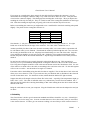
The data that might be useful to a user is:
Date
Time
U SkyRl Ambnt Sensr Block Hea KD32 1CVW
2005-01-17 11:20:01 C -43.9 -13.4
3.1 999.9 22 0100 0000
2005-01-17 11:30:02 C -40.7 -12.8
3.1 999.9 21 0100 0000
Date
Time
Fvr ... Cvr
054 ... 1.56
054 ... 1.56
local date
local time
V004G
16
Cloud Sensor User’s Manual
U
SkyRl
Ambnt
Sensr
Block
Hea
KD32 1CVW
Fvr
Cvr
temperature units (C or F). The lines with other letters are for factory use.
Sky-Amb. Temp. field from the Clarity window
Ambient Temp. field from the Clarity window
Sensor Temp. field from the Clarity window
for manufacturer use only
sensor head heater power setting in percent
these are flag bits. The ones possibly useful to the user are:
K
the “emergency observatory shutdown contact” is closed or has closed
since the last log line was generated if this is =1
V
the sensor head has detected “very cloudy”. This is a fixed threshold
determination independent of the threshold in the Clarity window. It is
used as part of the emergency observatory shutdown determination
W
the sensor head is wet., or has been wet at least once since the last log
line was generated.
sensor head firmware version number in decimal (the DIP IC is marked in hexadecimal)
Clarity version number.
As well as this, the log records include internal data that will be important for us if you are having
problems.
9.3 Registry
Every time the Clarity program is closed or a field is changed, it preserves the following information in
the registry:
•
•
•
•
•
•
•
•
•
location of the window on the screen
COM port number
Clear/Cloudy and Cloudy/V.C. threshold temperatures
Alert For and Alert Types check boxes
On top setting
logging setting
log file path and name
data file path and name
temperature unit.
These values are reinstated next time Clarity is run.
10. Remote Operation
The Clarity program has no special awareness of remote computing. It does however have some features
that will help:
• The COM or ActiveX interface detailed in section 13. To use this you would have to run suitable
software in the same computer that Clarity is running in (and to which the Cloud Sensor is
physically connected). This is software that you would write, or possibly from a third party.
• The single line data file facility described next.
V004G
17
Cloud Sensor User’s Manual
10.1 Single Line Data File Facility
A one line file for current sky data may be written by Clarity. This file may be accessed across networks
by using file sharing. Use the "Data File" button to set the file used, as is shown in section 9.1. The file
is written by Clarity for each message received from the Cloud Sensor (3 seconds apart). The format is:
Date
Time
U
SkyT AmbT SenT Hea W Since Now() Day's S
2005-06-03 02:07:23 C -28.5 18.7 22.5
3 0 00004 038506.08846 1
The immediately above line is an example of the only line in the file.
The fields mean:
Date
Time
U
SkyT
AmbT
SenT
Hea
W
Since
Now() Day's
S
local date yyyy-mm-dd
local time hh:mm:ss (24 hour clock)
temperature units, 'C' for Celsius or 'F' for Fahrenheit
sky-ambient temperature
ambient temperature
sensor case temperature
heater setting in %
wet flag, =0 for dry, =1 for wet
seconds since last valid data
VB6 Now() function result (in days)
SkyCondition (see the SkyCond enum in section 13).
Your software may parse this line either by using the fixed number of columns for each field, or by
sensing the spaces between the fields. The intention is to maintain this format in future revisions by
placing any changes as extra fields at the end of the line.
Clarity (written in Microsoft Visual Basic 6) opens the file with "Output Lock Write", writes the line, and
then closes the file. This might mean that occasionally your open to read the file will fail. To read in VB,
open this file for “Input", read the line with "Line Input", and then close the file. When opening this file
you MUST check for errors.
In your own software, check that "Now" is advancing (or that the date/time is recent). This confirms that
the file is being updated by Clarity. Check "Since" to confirm that Clarity is communicating with the
Cloud Sensor. If you do not do both checks, you might be badly misled.
This data file should be placed where Clarity is sure to have access to it at all times. If you put the file on
a different computer across a network from where Clarity is running, all will be well until either the
computer with the file or the network fails. Then Clarity will report continuous errors because it cannot
open the file.
When run, TestClarity (section 13) shows the contents of this one line file each time TestClarity does a
poll.
10.2 Potential Remoting Problems
If you operate the computer that Clarity is running on via some form of remote console software from
another computer, there can be problems. The Clarity executable has to be run in order to give alarms
V004G
18
Cloud Sensor User’s Manual
when needed. The operating system might not allow Clarity any CPU cycles when the operating system
or a privileged program crashes, or when the remote console software is waiting for the Internet link to
update the remote computer.
To see if you have the latter problem, set logging to "all" and then after a few minutes look at the log.
There should be a log line every 3 seconds (firmware 35H plus) or so. If there are large gaps and then
sudden bursts, you have the problem. Clarity attempts to alleviate this problem by reading Cloud Sensor
messages much faster (every .25 seconds) than the messages are produced. Thus Clarity can “catch up”.
This is a safety problem for your observatory but I am afraid that it is beyond the scope of the Cloud
Sensor to fix it. The emergency contact closure (section 11) will still function – this problem is part of
why that function is completely PC independent.
11. Contact Closure For Emergency Observatory Shutdown
The 3.5mm mono audio jack on the adaptor unit provides a way of performing an emergency observatory
shutdown even if your computer has failed. If the Cloud Sensor Unit is seeing a very cloudy sky or it is
wet, the inner conductor of the jack is shorted to the outer shell. This contact closure can be used
indirectly to activate shutter motors, etc. At all other times when there is power, the inner conductor is
floating electrically. For a time after a loss of power to the adaptor box, and just after power on, the
contact closure might be open or closed.
To use this facility you need to have some knowledge of electronics in order to connect it properly to your
dome/roof hardware.
The outer shell of the jack is connected to the ground pin of the DB9 RS232 connector – and that will be
connected to your computer’s ground, and to the building’s power ground when the DB9 is plugged into
your computer’s serial port. Your circuit must put between 0V and +30V on the inner conductor of the
jack – there is a 33V transorb across the jack. Your circuit must not allow more than 150 mA of current
to flow when the contact closes. Note that if you grossly exceed this current limit, you will burn out a
transistor inside the Cloud Sensor Unit – there is no protection against this.
When the Cloud Sensor is wet, the short across the jack is continuous. When it is “very cloudy” the short
is interrupted for 3 msec. every 3 seconds. This is done for internal reasons and probably will not be a
problem for your dome electronics. The “very cloudy” threshold is not the same as the one you set in the
Clarity software (which is in the possibly crashed computer!). Instead it is a computer independent
threshold of about -10°C (-18°F) that is built into the Cloud Sensor Unit itself.
After the rain has ended, the contact closure may not occur for “very cloudy” until the Cloud Sensor Unit
has evaporated any remaining moisture and partially cooled off. The observatory has already been closed
so this does not matter.
12. Error Messages
The error messages should be self explanatory. Some will appear in a message box, some in the large text
field in the Clarity window, and some that are of concern to the factory only appear in the log file. Clarity
will recover from almost all errors.
V004G
19
Cloud Sensor User’s Manual
If you plug/unplug things while Clarity is running, you often will get various communications errors.
Clarity will recover from these.
13. COM Interfacing
Note that this has nothing to do with the serial COM port. COM Automation is also referred to as
ActiveX. Thank Microsoft for the confusion in terminology.
This allows other software programs (including ones you write) to gather data from the Cloud Sensor.
For instance, you may want a program to park your telescope and close your observatory’s dome/roof if
very cloudy or rain is detected. The following are the properties available in the CloudSensor class. Note
that all temperatures are always in Celsius here. SecondsSinceGoodData provides a way to check that the
computer is communicating with the Cloud Sensor properly.
Please be sure that you know how to use COM before you try it with Clarity, especially if your program is
multithreaded. Obscure problems arise that look like Cloud Sensor failures but aren’t, if you break the
rule that an object must be created, used, and deleted on the same thread.
TestClarity (which is installed along with Clarity) is a simple Microsoft Visual Basic 6 program that uses
this COM facility. The source code as well as an executable is provided, and these are installed into
…\Program Files\BoltwoodSystems \Clarity\TestClarity. This is meant to be just an example and it might
not be a fully robust program.
Please do use: Set cloud = CreateObject("Clarity.CloudSensor")
as shown in TestClarity and not New to create the object. If you use New, your executable might not
work with the next version of Clarity because VB6 might change the class ID when we recompile Clarity
here. At the Cloud Sensor’s low data rates, there is no efficiency needn to use New.
The ActiveX Visual Basic 6 property declarations:
Public Enum SkyCond
skyUnknown = 0
skyClear = 1
skyCloudy = 2
skyVeryCloudy = 3
skyWet = 4
End Enum
Public Property Get SkyCondition() As SkyCond
is derived from the rawer properties below.
Public Property Get RelSkyT() As Double
is the Clarity window Sky-Amb. Temp. field in Celsius.
Public Property Get AmbientT() As Double
is the Clarity window Ambient Temp. field in Celsius.
Public Property Get SensorT() As Double
is the Clarity window Sensor Temp. field in Celsius.
V004G
20
Cloud Sensor User’s Manual
Public Property Get WetF() As Boolean
is true if the Clarity window square “wet” is blue.
Public Property Get HeaterPercent() As Double
is the sensor head heater power setting in percent.
Public Property Get CloudyThreshT() As Double
is the value in the Clear/Cloudy threshold field in the Clarity window in Celsius.
Public Property Get VCloudyThreshT() As Double
is the value in the Cloudy/V.C. threshold field in the Clarity window in Celsius.
Public Property Get Fahrenheit() As Boolean
is true if ºF was used in the Clarity window.
Public Property Get SecondsSinceGoodData() As Long
allows you to see if data is arriving properly from the Cloud Sensor Unit. There is data about
every 3 seconds so allow, say, 15 seconds in order to not report a failure due to bad messages
from lightning, etc.
14. Warranty
Boltwood Systems Corporation warranties the Cloud Sensor against manufacturing defects for one year
from the date of purchase. This warranty does not cover damage due to improper installation, exposure to
heavily polluted or corrosive atmospheres, intentional damage or tampering, lightning, or extreme
weather conditions. If you have a problem, please contact us before you ship the unit to us.
THIS WARRANTY IS EXCLUSIVE AND IN LIEU OF ALL OTHER WARRANTIES, WHETHER
EXPRESS OR IMPLIED, INCLUDING THE IMPLIED WARRANTIES OF MERCHANTABILITY,
FITNESS FOR A PARTICULAR USE, AND NON-INFRINGEMENT. This warranty gives you specific
rights. You may have other rights that vary from jurisdiction to jurisdiction.
DISCLAIMER
IN NO EVENT SHALL BOLTWOOD SYSTEMS CORPORATION OR DIFFRACTION LIMITED BE
LIABLE TO YOU FOR ANY SPECIAL, CONSEQUENTIAL, INDIRECT, OR SIMILAR DAMAGES,
INCLUDING ANY LOST PROFITS, LOST DATA, OR EQUIPMENT DAMAGE ARISING OUT OF
THE USE OR INABILITY TO USE THIS PRODUCT EVEN IF BOLTWOOD SYSTEMS
CORPORATION AND/OR DIFFRACTION LIMITED HAS BEEN ADVISED OF THE POSSIBILITY
OF SUCH DAMAGES. SOME JURISDICTIONS DO NOT ALLOW THE LIMITATION OR
EXCLUSION OF LIABILITY FOR INCIDENTAL OR CONSEQUENTIAL DAMAGES SO THE
ABOVE LIMITATION MAY NOT APPLY TO YOU. IN NO CASE SHALL BOLTWOOD SYSTEMS
CORPORATION’S AND DIFFRACTION LIMITED'S LIABILITY EXCEED THE PURCHASE PRICE
FOR THE PRODUCT.
V004G
21
Cloud Sensor User’s Manual
15. Contacting Us
For assistance with the Cloud Sensor, please contact us through our exclusive distributor, Diffraction
Limited. Go to http://www.cyanogen.com/support/tech_main.htm, or call (613) 225-2732. If you are
reporting a problem be sure to include a log file (see section 9.2) in your report if it is possibly relevant.
For further information on the Cloud Sensor, demo software, upgrades, or a copy of the manual, go to
http://www.cyanogen.com/products/cloud_main.htm.
V004G
22