1
Freescale Semiconductor, Inc.
Order Number: MCF5206EUMAD
Rev. 3, 7/2001
Freescale Semiconductor, Inc...
Semiconductor Products Sector
Errata to
MCF5206e ColdFire Microprocessor
User’s Manual, rev. 3.0
This errata describes corrections to the MCF5206e User’s Manual. For convenience, the
section number and page number of the errata item in the user’s manual are provided.
To locate the latest updates for this document, refer to the world-wide web at
http://www.motorola.com/Coldfire.
General
Every instance of “prescalar” should be changed to “prescaler.”
TOC, viii
Add an overbar to TS in paragraph number 2.5.5 listing Transfer Start
(TS)
TOC, xi
Add an overbar to TS in paragraph number 6.2.3 listing Transfer Start
(TS)
viii, TOC 2.10.1,2 Change the designation of the two timer modules from Timer 1 and 2
to Timer 0 and 1. Change every instance of TIN[1] to TIN[0] and
every instance of TIN[2] to TIN[1]. Similarly, change every instance
of TOUT[1] to TOUT[0], and change TOUT[2] to TOUT[1].
TOC, xiii
Change MARB to MPARK in section 8.4.1 Bus Master Arbitration
Control.
This document contains information on a new product under development by
Motorola. Motorola reserves the right to change or discontinue this product without
© Motorola, Inc., 2001. All rights reserved.
For More Information On This Product,
Go to: www.freescale.com
Freescale Semiconductor, Inc.
Changes
1.1, 1-1
Change the clock speed mentioned in the last sentence of the second
paragraph from 45 MHz to 40 MHz.
1.2, 1-4
Change the clock speed mentioned in the third-to-last bullet item from
45 MHz to 40 MHz.
1.2.1.3, 1-10
Change the reference to Table 1-3 to Table 1-1 and change the
designation of Table 1-2 to Table 1-1.
1.2.1.4, 1-10
Change the section designation from 1.2.1.4 to 1.3.1.4
Add the following tables.
Freescale Semiconductor, Inc...
Table 1-2. ColdFire Effective Addressing Modes
2
ADDRESSING MODES
SYNTAX
Register Direct
Data
Address
Dn
An
Register Indirect
Address
Address with Postincrement
Address with Predecrement
Address with Displacement
(An)
(An)+
–(An)
(d16,An)
Address Register Indirect with Index
8-Bit Displacement
(d8,An,Xi)
Program Counter Indirect
with Displacement
(d16,PC)
Program Counter Indirect with Index
8-Bit Displacement
(d8,PC,Xi)
Absolute Data Addressing
Short
Long
(xxx).W
(xxx).L
Immediate
#<xxx>
Errata to MCF5206e ColdFire Microprocessor User’s Manual, rev. 3.0
For More Information On This Product,
Go to: www.freescale.com
Freescale Semiconductor, Inc.
Changes
Table 1-3. MOVE Specific Effective Addressing Modes
SOURCE <EA>
DESTINATION <EA>
Dn
All
An
All
(An)
All
(An)+
All
-(An)
All
Dn
(d16,An)
(d16,PC)
An
(An)
Freescale Semiconductor, Inc...
(An)+
-(An)
(d16,An)
(d8,An,Xi)
(d8,PC,Xi)
Dn
An
(An)
(An)+
-(An)
Dn
(xxx).W
(xxx).L
An
(An)
(An)+
-(An)
Dn
#<xxx>
An
(An)
(An)+
-(An)
1.2.1.5, 1-10
Change the section designation from 1.2.1.5 to 1.3.1.5.
1.3.17, 1-18
Change the clock speed mentioned in the first paragraph from 45 MHz
to 40 MHz.
2.1, 2-1
Remove overbars from PP[7:4], PST[3:0], and the 4 over the arrow
connecting PP[7:4] to the General Purpose I/O Port in Figure 2-1
Errata to MCF5206e ColdFire Microprocessor User’s Manual, rev. 3.0
For More Information On This Product,
Go to: www.freescale.com
3
Freescale Semiconductor, Inc.
Changes
2.1, 2-1
Change every instance of TOUT[1] to TOUT[0], and change
TOUT[2] to TOUT[1]. In addition to the table of contents, such
changes are required in the locations listed in the following table.
Page
Section
Item
2-1
2.1
Figure 2-1
2-3
2.1
Table 2-1
2-15
2.10
first paragraph
2.10.1
heading
first paragraph
Freescale Semiconductor, Inc...
2.10.2
heading
first paragraph
2.1, 2-1
2.11.1
first paragraph
2-21
2.17
Table 2-12
14-3
14.4.1
Table 14-1
14-6
14.4.1.5
example code, Timer Init.
Insert the following text:
NOTE: The TRST signal does not work. All mention of this signal
should be stricken from the book. To reset the JTAG TAP controller,
TMS must be held high for 5 consecutive rising edges of TCK, as
specified in IEEE 1149.1.
Strike out the signal name TRST as it appears in the following figures:
Figure 2-1 on page 2-1; Figure 16-1 on page 16-2; Figure 16-2 on page
16-7; Figure 16-3 on page 16-8; Figure 16-4 on page 16-9; Figure 1716 on page 17-22, Figure 18-1 on page 18-2
Strike out the signal name TRST as it appears in the following tables:
Table of Contents, ix; Table 2-1, 2-3; Table 2-12, 2-21; strike both the
name and signal description in Table 16-1, 16-3; Index, Index-7
2-3
Replace the following line in Table 2-1.
Test Reset/
Development Serial Clock
TRST/DSCLK
Asynchronous JTAG reset input/
Debug serial clock input
In/
In
DSCLK
Debug serial clock input
In
with:
Development Serial Clock
2.5.4, 2-9
4
Add an overbar to TS in Table 2-9 (ATM Encoding) column headings.
Errata to MCF5206e ColdFire Microprocessor User’s Manual, rev. 3.0
For More Information On This Product,
Go to: www.freescale.com
Freescale Semiconductor, Inc.
Changes
2.5.7, 2-11
2.14.3, 2-17
The note at the top of the page should read as follows:
The internal synchronized version of ATA is referred to as
“internal asynchronous transfer acknowledge.’’ During a read
cycle, data is latched on the rising edge of CLK when the
internal asynchronous transfer acknowledge is asserted.
Consequently, data must remain valid for at least one and a half
CLK cycles after the assertion of ATA. Similarly, during a write
cycle, data is driven until the falling edge of CLK when the
internal asynchronous transfer acknowledge is asserted.
Replace section 2.14.3 with the following:
Freescale Semiconductor, Inc...
Development Serial Clock (DSCLK)
The DSCLK input signal is used as the development serial clock for
the serial interface to the debug module, and is enabled when
MTMOD=1.The maximum frequency for the DSCLK signal is 1/2 the
CLK frequency. See Section 15: Debug Support section for
additional information on this signal.
2.15.2, 2-18
Replace section 2.15.2 with the following note:
NOTE: The TRST signal does not work. All discussion of this signal
should be stricken from the book. To reset the JTAG TAP controller,
TMS must be held high for 5 consecutive rising edges of TCK, as
specified in IEEE 1149.1.
2.16.2, 2-20
Replace the last sentence in the first paragraph of section 2.16.2 with
the following:
Note that HIZ does not override JTAG operation.
2-21
Replace the following line in Table 2-12
Test Reset/Development Serial
Clock
TRST/
DSCLK
In/
In
Low/
-
-/
-
DSCLK
In
-
--
with
Development Serial Clock
3.2.2, 3-4
Add the following note.
NOTE:
Additional information about programming the 5206e integer
MAC can be found in the Hardware Multiply/Accumulate
section of the recently revised 5307 User’s Manual (rev. 2).
While the 5206e MAC module is nearly identical to the 5307’s,
the user is cautioned to be mindful of the differences –
specifically the absence of fractional operand support on the
5206e.
Errata to MCF5206e ColdFire Microprocessor User’s Manual, rev. 3.0
For More Information On This Product,
Go to: www.freescale.com
5
Freescale Semiconductor, Inc.
Freescale Semiconductor, Inc...
Changes
3.4, 3-7
Change the label of bits 27 and 26 in Figure 3-5 from FS[3:0] to
FS[3:2]
3.8, 3-15
The timing originally published in the 5206e manual for the multiply
instructions were correct for the older 5206 which did not have a
hardware multiplier-accumulator (MAC). Because the 5206e does
have a MAC its multiply instructions execute substantially faster than
was originally stated. Replace the following rows in Table 3-8:
MULS.W
<ea>,Dx
9(0/0)
11(1/0)
11(1/0)
11(1/0)
11(1/0)
12(1/0)
11(1/0)
9(0/0)
MULU.W
<ea>,Dx
9(0/0)
11(1/0)
11(1/0)
11(1/0)
11(1/0)
12(1/0)
11(1/0)
9(0/0)
MULS.L1
<ea>,Dx
18(0/0)
20(1/0)
20(1/0)
20(1/0)
20(1/0)
—
—
—
MULU.L1
<ea>,Dx
18(0/0)
20(1/0)
20(1/0)
20(1/0)
20(1/0)
—
—
—
with:
MULS.W
<ea>,Dx
4(0/0)
6(1/0)
6(1/0)
6(1/0)
6(1/0)
7(1/0)
6(1/0)
4(0/0)
MULU.W
<ea>,Dx
4(0/0)
6(1/0)
6(1/0)
6(1/0)
6(1/0)
8(1/0)
6(1/0)
4(0/0)
MULS.L
<ea>,Dx
6(0/0)
8(1/0)
8(1/0)
8(1/0)
8(1/0)
-
-
MULU.L
<ea>,Dx
6(0/0)
8(1/0)
8(1/0)
8(1/0)
8(1/0)
-
-
3.8, 3-15
DIVS.L
DIVU.L
Replace the timing information for the DIVS.L and DIVU.L
instructions with the following:
<ea>,Dx
<ea>,Dx
3.8, 3-16
REMS.L
REMU.L
37(1/0)
37(1/0)
37(1/0)
37(1/0)
37(1/0)
37(1/0)
37(1/0)
37(1/0)
Add the following rows containing the remainder instruction (REMU
and REMS) timing to Table 3-8:
<ea>Dx
<ea>Dx
3.9, 3-17
CPUSHL
35(0/0)
35(0/0)
35(0/0)
35(0/0)
37(1/0)
37(1/0)
37(1/0)
37(1/0)
37(1/0)
37(1/0)
37(1/0)
37(1/0)
Add the following line to Table 3-9 (Miscellaneous Instruction
Execution Times) describing the timing of the “Push and Invalidate
Cache Line” instruction.
(bc),(Ax)
—
11(0/1)
—
—
—
—
—
—
3.9, 3-17
In Table 3-9, strike out the timing information for the WDDATA #xxx
instruction. In 52xx devices the WDDATA instruction only supports
memory operands.
4.2, 4-2
Annotate Figure 4-1 to correct the following errors.
The tag array should compare bits 31-12, not bits 31-9.
The tag array elements should be numbered from 0-255, not 0-31.
The data array elements should be numbered 0-1023, not 0-127.
6
Errata to MCF5206e ColdFire Microprocessor User’s Manual, rev. 3.0
For More Information On This Product,
Go to: www.freescale.com
Freescale Semiconductor, Inc.
Changes
6.2.7, 6-3
Add an overbar to TS in Table 6-3 (ATM Encoding) column headings.
6.7, 6-49
Delete the following sentence from paragraph three as shown:
An interrupt must be held valid for at least two consecutive CLK periods to be considered
a valid input.
6.7, 6-49
Change the note on page 6-49 to read as follows:
Freescale Semiconductor, Inc...
NOTE:
All interrupts are level sensitive and must remain stable and
valid until the interrupt is acknowledged for the interrupt to be
reliably detected. Interrupt 7 is both level sensitive and edge
sensitive.
6.7.1, 6-52
Add the following paragraph before the note.
A chip select can be programmed to assert during the interrupt
acknowledge cycle by mapping the chip select address to the $7FFFFF
appearing on A[27:5]. For example, setting CSAR1= $07FF causes
CS1 to assert during the interrupt acknowledge cycle.
6.11.1, 6-82
Correct the RSTO, BD, and BR signals in Figure 6-49 to show them
remaining in a high impedance state until RSTI and HIZ are negated.
Add an inversion bar above “HIZ” in Figure 6-49.
Correct the second paragraph to read as follows:
TS must be pulled up or negated during master reset. When the assertion of RSTI is
recognized internally, the MCF5206e asserts the reset out pin (RSTO). RSTO is asserted as
long as RSTI is asserted when RSTI is negated, and remains asserted for 32 CLK cycles
after RSTI is negated. For proper master reset operation, RSTI and HIZ must be asserted
and negated simultaneously.
Add the following sentence to the last paragraph.
With the assertion of TS, reset exception processing starts 54 clock
cycles after RSTI is negated.
6.11.2, 6-83
Add an inversion bar above “HIZ” in Figure 6-50.
Correct the second paragraph to read as follows:
TS must be pulled up or negated during normal reset. When the assertion of RSTI is
recognized internally, the MCF5206e asserts the reset out pin (RSTO). RSTO is asserted as
long as RSTI is asserted when RSTI is negated, and remains asserted for 32 CLK cycles
after RSTI is negated. For proper normal reset operation, HIZ must be negated as long as
RSTI is asserted.
Errata to MCF5206e ColdFire Microprocessor User’s Manual, rev. 3.0
For More Information On This Product,
Go to: www.freescale.com
7
Freescale Semiconductor, Inc.
Changes
6.11.2, 6-84
Change the last sentence to read:
The IPL[2:0] signals are internally synchronized on consecutive falling and rising clocks in
a manner identical to RSTI and HIZ.
Freescale Semiconductor, Inc...
7.3, 7-3
Add the following text:
NOTE: When reading the four DMA source and destination registers
(DMA0SAR, DMA1SAR, DMA0DAR, DMA1DAR), the data for
bits [7:0] will echo the data on bits [15:8]. Writes to these registers
function normally. If the source increment (SINC) or destination
increment (DINC) bit of the DMA control register is set, the SAR and
DAR registers will increment, respectively, with each transfer.
This behavior complicates observation of DMA transfers since the
user generally cannot read a correct value from SAR or DAR. The
progress of DMA transfers can be monitored by reading the DMA
byte count register.
7.3, 7-3
Replace the first note with the following:
NOTE: The DMA cannot access the SRAM that is resident on-chip.
Nor can it perform transfers in or out of the on-chip peripherals. Use
the core CPU to access on-chip peripherals.
7.4.4, 7-8
In the discussion of the auto-align field, change the reference to the
auto alignment section from 7.10.2.2 to 7.7.2.2.
7.4.5, 7-11
Add the following note describing the action of the DONE bit.
NOTE:
Setting the DONE bit does not change any other DMA
programming nor disable the channel. An aborted transfer is
restarted if another DMA request is received (for example,
from an external asynchronous source) before the DMA
channel has been reprogrammed but after the DONE bit is set.
7.4.6, 7-12
The last sentence mentioning SMEN and SIVOE actually refers to
internal signals that the user should not be concerned with. Strike it
out.
The register is selected when both the SMEN and SIVOE signals are
asserted.
7.5.1, 7-12
8
Add the following paragraphs.
Errata to MCF5206e ColdFire Microprocessor User’s Manual, rev. 3.0
For More Information On This Product,
Go to: www.freescale.com
Freescale Semiconductor, Inc.
Changes
7.5.1.1 Exceptions to Normal Cycle Steal Operation
When the cycle steal (CS) mode is set in DCR, the DMA controller module does not
perform a single read/write transfer if multiple channels are active. For example:
• if DMA channel 1 is set to cycle steal mode,
• and the first request for DMA channel 1 has already occurred,
• and then a second DMA channel is started,
then, instead of a single transfer, DMA channel 1 will completely transfer the number of
bytes programmed in the BCR, thus ignoring the setting of the cycle steal mode bit. Using
only the lowest priority channel in cycle steal mode avoids this behavior.
Freescale Semiconductor, Inc...
7.6.1, 7-13
Add the following paragraph.
7.6.1.1 DMA to External DRAM
When accessing external DRAM with a DMA channel in single address mode
DCR[S_RW] controls the DRAMW pin as well as R/W, and the DRAM controller still
initiates a TA signal internally. The size pins, SIZ[1:0], are driven by the processor when it
has control of the bus and can be decoded along with other signals to create a DMA
acknowledge.
7.7.1.1, 7-14
Add the following paragraphs.
7.7.1.1.1 Some Considerations Regarding Internal Bus Arbitration and
DMA Writes
To ensure all DMA write requests are serviced, even under unusual
circumstances, do one or both of the following.
• Use processor writes to set the DMA start bits. That is, do not set the
external DMA request bit DCR[EEXT].
• If multiple DMA channels are used concurrently, then have only a
single channel running instantaneously by using the external DMA
request.
7.7.1.2, 7-15
Add the following paragraphs.
Errata to MCF5206e ColdFire Microprocessor User’s Manual, rev. 3.0
For More Information On This Product,
Go to: www.freescale.com
9
Freescale Semiconductor, Inc.
Changes
7.7.1.2.1 Some Considerations When Using Multiple Channels
When multiple internal DMA channels are used, the previously active channel’s
DCR[SINC] value is used for the first DMA transfer on the newly active channel. This
effect is only observable when the active channel is interrupted during a transfer by a DMA
request from another channel, and one channel is programmed to increment its source
address register (SAR) while the other is not.
Freescale Semiconductor, Inc...
For example, when channel 2 gets the bus, it's SAR will increment after the first transfer if
the following two conditions are met.
• DMA channel 1 is programmed to increment source addresses and
channel 2 is not
• channel 2 initiates a DMA request while channel 1 is doing a transfer
This could cause complications if channel 2 was being used as a FIFO.
Furthermore, if:
• channel 1 is programmed not to increment its SAR but channel 2 is set
to increment,
• and channel 2 initiates a DMA request while channel 1 is doing a
transfer,
then when channel 2 gets the bus, it's SAR is controlled by the previously active channel
setting and does not increment after the first transfer. While channel 2’s SAR does
increment after all subsequent transfers, two writes in the same address occur.
This behavior can be avoided by one or both of the following strategies:
• ensure no multiple concurrent internal DMA requests
• ensure all DMA channels have identical incrementing schemes (that
is, DCR[SINC] is programmed the same for all channels).
7.7.2.1, 7-15
Change the reference to Figure 7-7 to read Figure 7-6.
7.7.2.1, 7-16
Change the EXT_REQ[3:0] signal name in Figure 7-6 to DREQ[1:0]
as follows:
CLOCK
DREQ[1:0]
EXT_REQ[3:0]
7.7.2.1, 7-16
10
Add the following paragraphs.
Errata to MCF5206e ColdFire Microprocessor User’s Manual, rev. 3.0
For More Information On This Product,
Go to: www.freescale.com
Freescale Semiconductor, Inc.
Changes
7.7.2.1.1 DREQ Timing In Cycle Steal Mode
Freescale Semiconductor, Inc...
In cycle-steal mode (DCR[CS] = 1), the read/write transaction is limited to a single transfer.
DREQ must be negated appropriately to avoid generating another request. For dual-address
transfers, DREQ must be negated before TS is asserted for the write portion. For singleaddress transfers, DREQ must be negated before TS is asserted for the transfer.
NOTE:
Additional timing diagrams depicting DREQ and other DMA
transaction signals can be found in the DMA section of the
recently revised MC5307 User’s Manual. Although the 5307
and 5206e share the same DMA module, the user is cautioned
to be mindful of their differences when applying 5307 data to
5206e designs.
8.2.5, 8-6
Add the following paragraphs:
8.2.5.1 Special Conditions Involving Level 7 Interrupt
Under certain conditions the execution of a MOVE to SR or RTE instruction which may
cause a level 7 interrupt request to go undetected by the processor (that is, the core never
responds with a level 7 interrupt exception).
Level 7 interrupts are treated differently than all other interrupts since they are edgesensitive (versus level-sensitive). The processor has special logic to recognize the high-tolow assertion edge of the active-low interrupt 7 request. During a very small window of
time when a level 7 interrupt request is asserted while the processor is executing certain
variations of the MOVE to SR or RTE instructions, the processor will ignore the interrupt
request. This ignorance only occurs when the execution of the MOVE to SR or RTE
instruction loads a value of “7” into the 3-bit interrupt mask level of the status register.
NOTE:
The typical level 7 interrupt service routine, where the interrupt
request is negated before the RTE is executed, does not cause a
level 7 interrupt to go undetected.
To ensure all the level 7 interrupts are detected, load an operand of “6” into the 3-bit
interrupt mask of the status register to mask interrupt levels 1-6 for the MOVE to SR or
RTE instructions. The use of this new interrupt mask level does not effect the ability to
inhibit interrupts, since values of 6 or 7 both mask levels 1-6. A level 7 interrupt service
routine would need to load an operand of “7” into the interrupt mask until the level 7
interrupt source is negated, otherwise another level 7 interrupt would be generated if the
interrupt mask is lowered and the level 7 request is still present.
8.2.5, 8-4
Delete the following sentence from paragraph one as shown:
An interrupt must be held valid for at least two consecutive CLK periods to be considered
a valid input.
Errata to MCF5206e ColdFire Microprocessor User’s Manual, rev. 3.0
For More Information On This Product,
Go to: www.freescale.com
11
Freescale Semiconductor, Inc.
Changes
8.3.2.1, 8-8
Change the heading of the first paragraph following the MBAR
register figure to read, “BA[31:10 14] – Base Address”, to show that
only bits 31 through 14 are valid address bits.
Modify the register diagram to show only bits 31 through 14 are valid.
Bits 13, 11, 12 and 13 are reserved.
8.3.2.4, 8-12
Replace the last paragraph of this section with the following:
Freescale Semiconductor, Inc...
At system reset, all unreserved bits are set. The IMR is a 16-bit read/
write register except for bits [15:14]. These bits always read as 0.
Writes to IMR[15:14] function normally. If reads of IMR[15:14] are
required, store the written value in a separate memory location
whenever IMR is updated.
8.3.2.4, 8-12
Modify the Interrrupt Mask Register diagram to show 1 as the reset
state for DMA0 and DMA1.
8.3.2.10, 8-16
Change the second paragraph to read as follows:
The PAR is an 8 16-bit read-write register. At system reset, all bits are
cleared.
Add the following paragraph.
“PAR15 – PAR10 Pin Assignment Bits 15 -10
Unused.”
The heading for the PAR9 bit discussion should follow the register
figure, rather than preceed it. Annotate accordingly.
8.3.2.10, 8-17
In discussion of PAR bit 4, change the words “Parallel Port” to
“general purpose I/O” as shown below.
0 = Output Parallel Port general purpose I/O signals PP3 - PP0 on
PP[3:0]/DDATA[3:0] pins
8,9.1, 8-18
Change MARB to MPARK in the section title and the first paragraph.
Change the register figure annotation as follows:
“Bus Master Arbitration Control (MARB) (MPARK)”
9.3.3.1, 9-9
Add the following paragraph.
Figure 9-2 also applies to auto-acknowledge mode with zero wait
states. For nonzero wait states, the same timing diagram applies with
the specified number of wait states inserted between C1 and C2. When
running back-to-back asynchronous transfers to the same peripheral,
the minimum time between deasserting CS and then reasserting it is
one clock cycle.
12
Errata to MCF5206e ColdFire Microprocessor User’s Manual, rev. 3.0
For More Information On This Product,
Go to: www.freescale.com
Freescale Semiconductor, Inc.
Changes
9.3.3.1, 9-9
Add the following paragraphs.
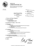
9.3.3.1a Nonburst Transfer with Address Setup, No Address Hold,
No Wait State.
.
C1
C2
CLK
TS
Freescale Semiconductor, Inc...
A[27:0]
$ADDR
R/W
TT[1:0]
$0
ATM
SIZ[1:0]
$0
D[31:0]
TA
TEA
ATA
CS
WE[3:0]
Figure 1. Longword Write Transfer from a 32-Bit Port
(Address Setup, No Wait State, No Address Hold)
Errata to MCF5206e ColdFire Microprocessor User’s Manual, rev. 3.0
For More Information On This Product,
Go to: www.freescale.com
13
Freescale Semiconductor, Inc.
Changes
Clock 1 (C1)
The write cycle starts in C1. During C1, the MCF5206e places valid values on the address
bus (A[27:0]) and transfer control signals. The transfer type (TT[1:0]) signals identify the
specific access type and access type and mode (ATM) is driven low to identify the transfer
as data. The read/write (R/W) signal is driven low for a write cycle, and the size signals
(SIZ[1:0]) are driven low to indicate a longword transfer. The MCF5206e asserts transfer
start (TS) to indicate the beginning of a bus cycle. Note WE[3:0] are never asserted.
Freescale Semiconductor, Inc...
Clock 2 (C2)
During C2, the MCF5206e asserts the appropriate chip select (CS) for the address being
accessed, negates transfer start (TS), drives access type and mode (ATM) high to identify
the transfer as supervisor, and drives data onto D[31:0]. If the selected device(s) is ready to
latch the data, it latches D[31:0] and asserts the transfer acknowledge (TA). At the end of
C2, the MCF5206e samples the level of TA. If TA is asserted, the transfer of the longword
is complete, and the MCF5206e negates CS after the next rising edge of CLK. If TA is
negated, the MCF5206e continues to sample TA and inserts wait states instead of
terminating the transfer. The MCF5206e continues to sample TA on successive rising edge
of CLK until it is asserted. If the bus monitor timer is enabled and TA is not asserted before
the programmed bus monitor time is reached, the cycle is terminated with an internal bus
error.
9.3.3.6, 9-18
Add an overbar to TS in Figure 9-7, signal label. Also, in that same
figure, add overbars to the following signal names as shown: R/W, TA,
TEA, ATA, CS, WE[3:0]
9.4.2.3, 9-34
Add the following sentence to the first paragraph.
Setting ASET delays the assertion of CS for both reads and writes.
10.2, 10-1
Change the reference in the last sentence to the SIM subsection from
6.3.2.10 to 8.3.2.10.
10.3.1, 10-1
Change every reference to port A data direction register from PPDDR
to PADDR. For example, Table 10-1, first row.
Change every reference to port A data register from PPDAT to
PADAT. For example, Table 10-1, second row.
10.3.1, 10-2
Change port A data register diagram label from PPDAT to PADAT.
14
Errata to MCF5206e ColdFire Microprocessor User’s Manual, rev. 3.0
For More Information On This Product,
Go to: www.freescale.com
Freescale Semiconductor, Inc.
Changes
10.3.2.1, 10-2
Correct the output pin column of Table 10-2 to read as follows:
Freescale Semiconductor, Inc...
Table 10-2. Data Direction Register Bit Assignments
Data Direction Register Bit
OUTPUT PIN
DDR7
PP[7]/PST[3]
DDR6
PP[6]/PST[2]
DDR5
PP[5]/PST[1]
DDR4
PP[4]/PST[0]
DDR3
PP[3]/DDATA[3]
DDR2
PP[2]/DDATA[2]
DDR1
PP[1]/DDATA[1]
DDR0
PP[0]/DDATA[0]
10.3.2.2, 10-3
Correct the designation of Table 10-4 to read Table 10-3.
11.3.2.6, 11-13
Table 11-8, change the column heading from CAS to “Column
Address.”
Add the following paragraphs.
Tables 11-6, 11-7, and 11-8 and the associated text describe connections for symmetrical
DRAM. If your DRAM is asymmetrical (different number of column and row addresses)
then the instructions accompanying Tables 11-6, 7, and 8 are not sufficient. The following
procedure allows correct design of asymmetrical DRAM connections using Tables 11-6, 7,
and 8.
1. Find the table corresponding to your DRAM port and page size.
2. Starting from the bottom of the table, assign DRAM address pins
using only the shaded connections until you run out of column
addresses.
3. Continue following the table to make the remaining connections, but
now use every address line (not just the shaded lines) until you have
connected all of the address pins on your DRAM.
Errata to MCF5206e ColdFire Microprocessor User’s Manual, rev. 3.0
For More Information On This Product,
Go to: www.freescale.com
15
Freescale Semiconductor, Inc.
Changes
Here is an example:
If you wanted to connect a 32-bit, 1Kbyte page size with 8 column address lines and 11 row
address lines then you would use the connections shown in the table below.
Freescale Semiconductor, Inc...
Table 2-3. 32-bit Port Size, 1 KB Page Size Asymmetrical DRAM Connections
5206e Address
Pin
DRAM
Address Pin
Column
Address Line
Row Address
Line
A10
0
Y
Y
A11
1
Y
Y
A12
2
Y
Y
A13
3
Y
Y
A14
4
Y
Y
A15
5
Y
Y
A16
6
Y
Y
A17
7
Y
Y
A18
8
Y
A19
9
Y
A20
10
Y
11.3.2, 11-15
In the third line change DCMR: $001E0000 to $003E0000.
11.5, 11-61
Change the second sentence in the first paragraph to read 1 MByte
instead of 4 MByte.
Change the last sentence in the first paragraph from (1 MByte x 32) to
(256 KByte x 32).
Change the transfer address mask bit range for the DCMR0 in the
second paragraph from 18 - 16 to 19 - 17. (This appears on the second
to last line on the page.)
11.5, 11-62
Change the address range upper bound for the DRAM initialization
example from $001EFFF to $001FFFFF.
Change the commentary in the code example from - 0x001effff to 0x001fffff
12, 12-1
Add the following paragraphs:
NOTE:
Throughout the document, “system clock” refers to the main
processor clock.
To select internal clock for both transmit and receive, load UCSR with 0xDD.
16
Errata to MCF5206e ColdFire Microprocessor User’s Manual, rev. 3.0
For More Information On This Product,
Go to: www.freescale.com
Freescale Semiconductor, Inc.
Changes
12.3.1, 12-5
Add the following paragraphs.
12.3.1.1 Calculating Baud Rates
The desired baud rate is specified by the following formula:
UBG1 and UBG2 = (system clock/(baudrate * 32)
For example, to select 19200 baud, write 0x0 to UBG1 and 0x57 to UBG2. See the UART
section of the 5307 User’s Manual (Rev. 2.0) for more information.
12.3.1, 12-5
Add the following paragraphs.
Freescale Semiconductor, Inc...
For example, the maximum UART baud rate using an external clock,
TIN, is computed as follows.
Note that the maximum TIN frequency corresponds to the minimum
period. From Table 17-10, the minimum TIN cycle time (T1) is
specified as 3 clocks, indicating a maximum operating frequency of
one-third the system clock. The maximum processor clock rate is
54 MHz, giving a maximum baud of 54 ÷ 3, or 18 MHz.
12.4.1.12, 12-5
Add the following note.
NOTE:
See the UART section of the recently revised MCF5307 User’s
Manual (rev 2.) for additional information. Although the 5307
and 5206e share the same UART module, the user is cautioned
to be mindful of their differences when applying 5307 data to
5206e designs.
12.5, 12-34
Strike out the second sentence beginning on the fifth line with,
“However, if the UART Interrupt Control Register. . .”
12.5, 12-35-39
Change the figure numbers on the UART Software Flowchart from
“11-” to “12-”.
13.5.2, 13-7
Annotate the next to last sentence to read as follows:
The serial bit clock frequency is equal to the CPU clock divided by the divider shown in
Table 13-2. , which also shows the serial bit clock frequency for a 33MHz internal operating
frequency
Add the following paragraphs:
The M-Bus frequency depends on the CPU frequency and is calculated according to the
following formula:
M-Bus frequency = CPU frequency/(selected divider)
The user specifies a divider by writing its MBC5-0 value (shown in Table 13-2) into
MFDR. For example, writing 0x07 into MFDR specifies a divider of 68. A divider value
must be chosen large enough to ensure the resulting M-Bus frequency is always less than
100 KHz.
Errata to MCF5206e ColdFire Microprocessor User’s Manual, rev. 3.0
For More Information On This Product,
Go to: www.freescale.com
17
Freescale Semiconductor, Inc.
Changes
13.6.6, 13-14
Add the following paragraph:
In slave mode, the module will only respond to it's address and will not recognize I2C
'general call' (address 0) messages. Also in slave mode, there is no interrupt for the stop
condition so users must detect the end of a transmission either by counting bytes or by
polling for the stop condition.
14.5, 14-9
Add the following paragraphs.
14.5 Programming Example
Freescale Semiconductor, Inc...
Given a system clock of 40.550400 MHz, program a timer to generate one pulse every
milisecond. The formula to calulate the timeout period for the timer is shown below.
Timeout = (1/clock) × (1 or 16) × (TMR prescale value +1) × [timer reference register]
We get the desired result by setting the TMR prescale value, TMR[PS7-PS0], to zero
(yielding a divisor of 1), and loading the timer reference register, TRR[15:0], with 0x9E66.
Timeout = (1/40,550,500) × (1) × (1) × (0x9E66) seconds
Timeout = (2.466e-8) × (40550) seconds
Timeout = 0.001 seconds
15.2.2, 15-6
Add the following paragraphs:
15.2.2.1 Debug Captured Write after Exception may cause an
Extraneous PST = 0x1
There is a complex sequence of events that may cause the Version 2 debug module to output
an extraneous PST=1 value when capturing and displaying operand write data. The specific
sequence is:
4. The processor takes any type of exception.
5. Once the exception handler is entered, the very first operand to be
captured and displayed by the PST/DDATA logic is an operand write.
6. If the next instruction after the operand write is a non-memoryreferencing opcode (e.g., a register-to-register or immediate-toregister instruction), then the debug module may incorrectly output an
extraneous PST = 0x1 value before the write operand is captured and
displayed.
18
Errata to MCF5206e ColdFire Microprocessor User’s Manual, rev. 3.0
For More Information On This Product,
Go to: www.freescale.com
Freescale Semiconductor, Inc.
Changes
The resulting stream of PST values is as follows:
Table 15-1.5. PST Values
PST[3:0] Stream (HEX)
5
0
...
1
0
...
1
0
Correct
C
C
...
5
0
...
1
0
...
0
0
...
[89B]
1
0
..
.
[89B]
1
0
..
.
wrt marker
...
Extraneous PST
C
wrt inst
C
exception
Current
Position Comment
Freescale Semiconductor, Inc...
PST
NOTE:
The processor's operation is perfectly correct throughout this
sequence.
If a WDDATA.{B,W,L} instruction is included in the
exception handler before any instructions with operand writes,
the extraneous value does not occur.
If the first memory-referencing instruction in an exception
handler is a write, inserting a NOP instruction immediately
after it will prevent the extraneous value anomaly. If any
operand reads are performed before the first write, the NOP is
not required.
15.2.2.2 Non-Contiguous Stream of PST = 0xD Values During a
Debug Interrupt Exception
If the debug module is configured to generate a debug interrupt exception in response to a
breakpoint trigger, the processor responds by taking a special exception. While processing
this exception, the debug module usually outputs a contiguous stream of PST = 0xD values
until the exception completes and control is passed to the instruction defined by the
interrupt vector. This change-of-flow is signaled by PST = 0x5, which marks the end of the
exception processing. The only deviations to the PST = 0xD stream are operand markers
(PST = 0xB) associated with operand captures during the writing of the exception stack
frame.
Errata to MCF5206e ColdFire Microprocessor User’s Manual, rev. 3.0
For More Information On This Product,
Go to: www.freescale.com
19
Freescale Semiconductor, Inc.
Changes
If operand writes are being captured, sometimes the stream of PST = 0xD values is noncontiguous, and includes PST = 0x0 values. Note that the processor's operation is perfectly
correct throughout this sequence.
NOTE:
The user should ignore PST = 0x0 values occurring during a
debug interrupt and understand the debug interrupt exception
processing to be defined from the initial PST = 0xD until the
PST = 0x5 value. To ensure a contiguous stream of PST = 0xD
values, disable capturing of operand writes if debug interrupts
are enabled.
Freescale Semiconductor, Inc...
15.3.2,15-29
Insert a space between the bra.* instruction and the appropriate labels
in the assembly language examples so they read as follows:
align4
label1:nop
bra.b label1
OR
align4
label2:bra.w
15.3.3.6, 15-35
label2
In the description of the EMU bit, replace the bit description with the
following text:
Do not set bit 13 of the debug module's Configuration/Status Register.
The quickest entry into emulator mode after reset is created with the
following sequence:
1. While in the BDM initiation sequence, program a debug breakpoint
trigger event by an operand reference to address 0x0 or 0x4. As part
of this sequence, the debug interrupt vector must also be initialized to
the same address as the initial PC defined at address 4.
2. When the BDM “go” command is received by the processor, the reset
exception processing fetches the longwords at addresses 0 and 4 in
“normal mode” and then a debug interrupt is immediately generated
before the first instruction is executed.
3. Execution continues in emulator mode.
15.4, 15-38
Modify Figure 15-7 to show pin 9 as an output – draw an arrow
starting on the connector rectangle and pointing toward the “+5V”
label.
Add the following notes to Figure 15-7 describing Motorola’s
recommended BDM pinout on the 26-pin Berg connector.
Although pin 9 is labeled “+5V”, the appropriate voltage sourced by
pin 9 is BDM-tool-vendor specific. On the Motorola MCF5206eC3
evaluation boards this pin’s voltage is jumper-selectable between 3.3v
20
Errata to MCF5206e ColdFire Microprocessor User’s Manual, rev. 3.0
For More Information On This Product,
Go to: www.freescale.com
Freescale Semiconductor, Inc.
Changes
and 5v. Check with your tools vendor to determine the correct value in
your case.
Pin 21, labeled “Motorola reserved,” may be left floating.
intro, 16-1
Strike out the words, “either asserting TRST or”, in the second
paragraph so that it reads as follows:
Freescale Semiconductor, Inc...
. . .This architecture provides access to all of the data and chip control
pins from the board edge connector through the standard four-pin test
access port (TAP). and the active-low JTAG reset pin, TRST. . . .
16.2, 16-2
Replace every instance of JTAG with MTMOD. Note the overbar on
JTAG. Replace only those instances with the overbar.
16.3.1.2, 16-4
Strike out the words, “either asserting TRST or”, in the second
paragraph so that it reads as follows:
The IDCODE instruction is the default value placed in the instruction
register when a JTAG reset is accomplished by either asserting TRST
or holding TMS high while clocking TCK through at least five rising
edges and the falling edge after the fifth rising edge.
16.6, 16-8, 9
Change all instances of JTAG to MTMOD. Modify the last sentence
of paragraph 16.6 so that it reads as follows:
. . . (disconnection) or intentional fixing of TAP logic values, and 2)
Intentional disabling of the JTAG test logic by assertion of the
MTMOD signal (entering Debug mode)
16.6, 16-8, 9
Modify the last sentence of the second paragraph and Figure 16-3 so
they appear as follows:
Figure 16-3 shows pin values recommended for disabling JTAG with
the MCF5206e in JTAG mode (MTMOD=0).
VDD
•
TMS/BKPT
TDI/DSI
JTAG MTMOD
•
•
TRST/DSCLK
TCK
Errata to MCF5206e ColdFire Microprocessor User’s Manual, rev. 3.0
For More Information On This Product,
Go to: www.freescale.com
21
Freescale Semiconductor, Inc.
Changes
16.6, 16-8, 9
Strike out the references to TRST in the excerpt from the second
paragraph shown below so that it reads as follows:
. . . . This requires the minimum of either connecting the TRST pin to
logic 0, or connecting the TCK clock pin to a clock source that will
supply five rising edges and the falling edge after the fifth rising edge,
to ensure that the part enters the test-logic-reset state. The
recommended solution is to connect TRST to logic 0. Another
consideration is that the TCK pin does not have an internal pull-up as
is required on the TMS, TDI, and TRST pins; therefore, it should not
be left unterminated to preclude mid-level input values.
Freescale Semiconductor, Inc...
16.6, 16-8, 9
Change JTAG to MTMOD and strike out the reference to TRST in the
last paragraph so that it reads as follows:
A second method of using the MCF5206e without the IEEE 1149.1
logic being active is to select debug mode by placing a logic 1 on the
defined compliance enable pin, MTMOD. When MTMOD is a logic
1, then the IEEE 1149.1 test controller is placed in the test-logic-reset
state by the internal assertion of the TRST signal to the controller, and
the TAP pins function as Debug mode pins. While in JTAG mode,
input pins TDI/DSI, TMS/BKPT, and TRST/DSCLK have internal
pull-ups enabled.
16.6, 16-8, 9
Modify Figure 16-4 as shown below:
VDD
MTMOD
JTAG
TDI /DSI
DEBUG INTERFACE
TRST/DSCLK
DSCLK
TCK
22
Errata to MCF5206e ColdFire Microprocessor User’s Manual, rev. 3.0
For More Information On This Product,
Go to: www.freescale.com
Freescale Semiconductor, Inc.
Changes
17.1., 17-1
Add the following paragraph and table:
17.1.1a Power Consumption
Frequency
(MHz)
Power
Dissipation,
Typical (mW)
40
54
340
460
17.1.1b Low-Power State
Freescale Semiconductor, Inc...
Example power consumption for the 5206e in low-power state (after STOP instruction) is
shown in Table 17-1.1.
NOTE:
The low-power consumption numbers given below were
derived from a single set of measurements and are not
statistically representative of the MCF5206e. Motorola makes
no guarantees regarding these values. They are provided as an
example only. Your results may vary.
Table 17-1.1. Example Power Consumption in Low-Power State
17.1.2, 17-2
Clock Rate in
MHz
Power Dissipation
in mW
54
40
25
16
287
214
142
99
Replace the following line in Table 17-2,
Maximum operating junction temperature
TJ
TBD
oC
TJ
951, 1052
oC
with
Maximum operating junction temperature
1
2
Standard temperature devices
Extended temperature devices
Errata to MCF5206e ColdFire Microprocessor User’s Manual, rev. 3.0
For More Information On This Product,
Go to: www.freescale.com
23
Freescale Semiconductor, Inc.
Changes
17.2, 17-3
Replace Table 17-5 with the following:
Table 17.5. DC Electrical Specifications
Freescale Semiconductor, Inc...
CHARACTERISTIC
SYMBOL
MIN
MAX
UNIT
Operation voltage range
VDD
3.0
3.6
V
Input high voltage
VIH
2
5.5
V
Input low voltage
VIL
GND
0.8
V
Input signal undershoot
—
—
0.8
V
Input signal overshoot
—
—
0.8
V
Input leakage current @ GND, VIH=5.51
Iin
—
200
uA
ITSI
—
20
uA
IIL
0
1.0
mA
IIH
0
1.0
mA
Output high voltage, IOH = 5 mA (All signals2 except RAS[1:0],
CAS[3:0], DRAMW, TS, R/W, A[27:23]), IOH =11mA (RAS[1:0],
CAS[3:0], DRAMW, TS, R/W, A[27:23])
VOH
2.4
—
V
Output low voltage, IOL = 5 mA (All signals except RAS[1:0],
CAS[3:0], DRAMW, TS, R/W, A[27:23]), IOL =11mA (RAS[1:0],
CAS[3:0], DRAMW, TS, R/W, A[27:23])
VOL
—
0.5
V
Pin capacitance3
Cin
—
10
pF
ESD specification
Meets 100 V MM (machine model)
CLK, A[27:0], D[31:0], TS, SIZ[1:0], R/W, TA, ATA, TEA, IPL[2]/
IRQ[7], IPL[1]/IRQ[4], IPL[0]/IRQ[1], BG, RxD[2:1], CTS[2:1],
TIN[1:0], PP[7:0]/PST[3:0], DDATA[3:0], RSTI, TCK, HIZ, JTAG,
MTMOD
HI-Z (three-state) leakage current @GND, VDD
A[27:0], D[31:0], TS, TT[1:0], ATM, SIZ[1:0], R/W, TA, TDO/DSO
Signal Low Input Current, VIL = 0.8V
TMS/BKPT, TDI/DSI, TRST/DSCLK
Signal High Input Current, VIH = 2.0V
TMS/BKPT, TDI/DSI, TRST/DSCLK
1
Changes shown in bold face.
Note that open-drain signals require pull-up resistors and cannot source IOH
3 This specification periodically sampled but not 100% tested.
2
17.3.3, 17-5
In Table 17-8, change the Min specification for B1f to 3.0 ns for the
40 MHz device and 2.0 ns for the 54 MHz device.
In Table 17-8, change the Min specification for B5 to 7.0 ns for the
40 MHz device and 3.5 ns for the 54 MHz device.
17.3.3, 17-6
Add the following paragraph:
Although output signals that share a specification number have
approximately the same timing, due to loading differences they do not
necessarily change at the same time. However, they have similar
timings; that is, minimum and maximum times are not mixed.
24
Errata to MCF5206e ColdFire Microprocessor User’s Manual, rev. 3.0
For More Information On This Product,
Go to: www.freescale.com
Freescale Semiconductor, Inc.
Changes
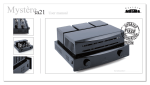
17.3.7, 17-10
Replace Figure 17-5 with the following:
CLK
B10a,b,c,d
ADDRESS &
ATTRIBUTES
B11
B7a
TS
Freescale Semiconductor, Inc...
B8a
B10a
B10a
ATM
B11
B11
B5
DATA IN
(READ)
B6
B13
B15
DATA OUT
(WRITE)
B14
B10a
WE[3:0]
B11
B1b
TA
B2a
B1c
ATA
B2b
B1d
TEA
B2a
NOTE: ADDRESS AND ATTRIBUTES REFER TO THE FOLLOWING SIGNALS:
A[27:0], SIZ[1:0], R//W, TT[1:0], ATM, and CS[7:0].
Figure 17-5. Read and Write Timing
Errata to MCF5206e ColdFire Microprocessor User’s Manual, rev. 3.0
For More Information On This Product,
Go to: www.freescale.com
25
Freescale Semiconductor, Inc.
Freescale Semiconductor, Inc...
Changes
17.3.8, 17-15
In Table 17-9, change the Min specification for T2 to 5.0 ns for the
40 MHz device and 3.0 ns for the 54 MHz device.
17.3.10, 17-17
In Table 17-11, change the Min specification for U1 to 3.0 ns for the
40 MHz device and 2.0 ns for the 54 MHz device. Also, change the
column heading in the last column from NAME to UNIT.
17.3.12.1, 17-18
In Table 17-12, “INPUT Timing Specifications Between SCL and
SDA,” change the Max specification for M3 to 1 mS for both clock
speeds. Change the Max specification for M5 to 1 mS for both clock
speeds.
17.3.12.2, 17-19
In Table 17-13, “Output Timing Specifications Between SCL and
SDA,” change the Max specification for M5 from TBD to 3 µS for
both clock speeds.
17.3.12.3, 17-19,20 Delete this section heading and Table 17-14, “Timing Specifications
Between CLK and SCL, SDA.” Also delete the associated timing
diagram Figure 17-13, “M-Bus Timing.”
17.3.14, 17-21
In Table 17-15, change the Min specification for P1 to 4.5 ns for the
40 MHz device and 3.0 ns for the 54 MHz device.
17.3.18, 17-21, 22 Strike out the timing information for TRST depicted in Table 17-16
and Figure 17-16.
18.1, 18-2
Change the label on pin 27 of Figure 18-1, from VSS to GND.
Figure 18-1., 18-2
On the package diagram and pinout figure, strike out TRST and
replace JTAG with MTMOD.
Appendix A-iv
Change PPDDR to PADDR.
Change PPDAT to PADAT.
Appendix A
Add the following entry to Appendix A.
$07
Index-7
26
MPARK
8
Bus Master Arbitration Control Register
Add an overbar to TS in Transfer Start index entry.
Errata to MCF5206e ColdFire Microprocessor User’s Manual, rev. 3.0
For More Information On This Product,
Go to: www.freescale.com
$00
R/W
Freescale Semiconductor, Inc.
Changes
Appendix C
1.1 Basic DRAM Parameters
Refresh size is the number of row addresses that must be cycled through to keep the DRAM
refreshed. A 4K refresh DRAM uses 12 row address bits (212 = 4K), and an 8K refresh
DRAM uses 13 row address bits.
The number of column address bits and the data bus width determine a DRAM's page size:
(page size in bytes) = (data bus width in bytes) * 2 ^ (number of column address bits)
Freescale Semiconductor, Inc...
A 16-bit DRAM with 9 column address bits has a page size of 1KB.
The basic “size” or storage capacity of a DRAM is the page size multiplied by the refresh
size. A DRAM with an 8K refresh and 1KB page size has an 8MB capacity.
When two 16-bit DRAMs are arranged in “parallel” to provide a 32-bit data bus (one chip
on D31..D16 and another on D15..D0), the processor should be configured for an effective
page size equal to twice the page size of one chip, because twice as much memory can be
accessed in this configuration without changing the row address.
A larger page size requires more circuitry inside the DRAM chip but improves overall
performance by reducing both the number of rows to refresh and the amount of page
switching.
Errata to Appendix C
For More Information On This Product,
Go to: www.freescale.com
27
Freescale Semiconductor, Inc.
Changes
1.2 Asymmetrical DRAM
Freescale Semiconductor, Inc...
When a DRAM has the same number of row addresses as column addresses it is called
symmetrical. When the number of row and column addresses are not the same the DRAM
is called asymmetrical. Most currently available DRAM is asymmetrical. All existing
asymmetrical DRAMs have more rows, and therefore more row address lines, than
columns and column address lines. In a transaction with an asymmetrical DRAM, the
complete row address is transferred first, then the column address is transferred using the
least significant address lines. If the processor is configured to use the same page size as
the “effective” page size of the DRAM, the DRAM should be connected to consecutive
address lines on the processor. The connection is illustrated in the following example.
Table 11-8.1 Two 16-bit asymmetric 1KB page size chips in “parallel”
to form a 32-bit data bus with 2KB page size
Port Size = 16-bit
MCF5206e BankPage = 2 Kbyte
Address line on
Address
DRAM
Row
Column
Pin
address Address
A11
A12
A13
A14
A15
A16
A17
A18
A19
A20
A21
A22
A23
IA11
IA12
IA13
IA14
IA15
IA16
IA17
IA18
IA19
IA20
IA21
IA22
IA23
IA2
IA3
IA4
IA5
IA6
IA7
IA8
IA9
IA10
A0
A1
A2
A3
A4
A5
A6
A7
A8
A9
A10
A11
A12
Section 11.3.2.4 describes connections for symmetrical DRAM. Symmetrical DRAM
addresses are transferred in two equal parts, with most of the row address first, then the rest
of the row address on the more significant bits and the column address on the less
significant bits. By making the two transfers of equal size rather than using a large row
address transfer followed by a small column address transfer like asymmetrical DRAM
does, fewer physical address lines are needed on the DRAM. Because the bits of the row
address that are transferred with the column address use some of the same physical
connections as some of the bits of the row address that were transferred previously, some
of the address lines from the processor should be skipped as shown by not being shaded in
Tables 11-6, 11-7 and 11-8.
In some cases, such as when connecting two 16-bit asymmetrical DRAM's with 2KB page
size in “parallel” to a 32-bit data bus, the resulting 4KB “effective” page size is larger than
the 5206e can handle directly using the asymmetrical method described above. The DRAM
chips have more column address bits than the number of consecutive column addresses
28
Errata to Appendix C
For More Information On This Product,
Go to: www.freescale.com
Freescale Semiconductor, Inc.
Changes
Freescale Semiconductor, Inc...
provided by the processor's multiplexing scheme. In such cases the extra DRAM column
address bits can be controlled by row address bits from the processor. This effectively
breaks up each of the bigger DRAM pages into what appears to the processor to be 2, 4, 8
(or more) different pages. The performance is the same as if a DRAM with the page size
the processor is configured for was used, because the processor inserts page switching
delays (transfers a new row address, etc.) whenever it thinks it is switching pages, even
though the “new page” (as seen by the processor) may actually be on the same page in the
DRAM (if the only processor row address bits that change are the ones connected to DRAM
column address bits).
The address line connections for interfacing DRAMs with a larger effective page size than
the processor configuration is a combination of the symmetrical and asymmetrical
methods. The number of column address lines that the DRAMs use should be connected
(starting with the least significant line) as shown in the manual for the symmetrical case
(including skipping some of the processor's address lines). Then the remaining address
lines (which the DRAMs use for the row but not column address) should be connected
consecutively, as in the asymmetrical case. The most significant processor address line used
should correspond with the size of the memory (A23 => 16MB, etc.).
Example: Two 16-bit asymmetric 1KB page size chips in “parallel” to get 32-bit data bus
while keeping a 1KB page size.
Table 1. Two 16-bit asymmetric 1KB page size chips in “parallel”
forming a 32-bit data bus with a 1KB page size
Port Size = 16-bit
MCF5206e BankPage = 2 Kbyte
Address line on
Address
DRAM
Row
Column
Pin
address Address
A10
A11
A12
A13
A14
A15
A16
A17
A19
A20
A21
A22
A23
IA10
IA11
IA12
IA13
IA14
IA15
IA16
IA17
IA19
IA20
IA21
IA22
IA23
IA2
IA3
IA4
IA5
IA6
IA7
IA8
IA9
IA18
A0
A1
A2
A3
A4
A5
A6
A7
A8
A9
A10
A11
A12
Example: Two 16-bit asymmetric 2KB page size chips in “parallel” to get 32-bit data bus
while keeping a 2KB page size.
Errata to Appendix C
For More Information On This Product,
Go to: www.freescale.com
29
Freescale Semiconductor, Inc.
Changes
Table 2. Two 16-bit asymmetric 2KB page size chips in “parallel”
forming a 32-bit data bus with a 2KB page size
Port Size = 16-bit
MCF5206e BankPage = 2 Kbyte
Address line on
Address
DRAM
Row
Column
Pin
address Address
Freescale Semiconductor, Inc...
A11
A12
A13
A14
A15
A16
A17
A18
A19
A21
A22
A23
30
IA11
IA12
IA13
IA14
IA15
IA16
IA17
IA18
IA19
IA21
IA22
IA23
IA2
IA3
IA4
IA5
IA6
IA7
IA8
IA9
IA10
IA20
A0
A1
A2
A3
A4
A5
A6
A7
A8
A9
A10
A11
Errata to Appendix C
For More Information On This Product,
Go to: www.freescale.com
Freescale Semiconductor, Inc.
Freescale Semiconductor, Inc...
Changes
Errata to Appendix C
For More Information On This Product,
Go to: www.freescale.com
31
Freescale Semiconductor, Inc...
Freescale Semiconductor, Inc.
DigitalDNA and Mfax are trademarks of Motorola, Inc.
The PowerPC name, the PowerPC logotype, and PowerPC 603e are trademarks of International Business Machines Corporation used by Motorola
under license from International Business Machines Corporation.
Information in this document is provided solely to enable system and software implementers to use PowerPC microprocessors. There are no express
or implied copyright licenses granted hereunder to design or fabricate PowerPC integrated circuits or integrated circuits based on the information in
this document.
Motorola reserves the right to make changes without further notice to any products herein. Motorola makes no warranty, representation or guarantee
regarding the suitability of its products for any particular purpose, nor does Motorola assume any liability arising out of the application or use of any
product or circuit, and specifically disclaims any and all liability, including without limitation consequential or incidental damages. “Typical” parameters
can and do vary in different applications. All operating parameters, including “Typicals” must be validated for each customer application by customer’s
technical experts. Motorola does not convey any license under its patent rights nor the rights of others. Motorola products are not designed, intended,
or authorized for use as components in systems intended for surgical implant into the body, or other applications intended to support or sustain life, or
for any other application in which the failure of the Motorola product could create a situation where personal injury or death may occur. Should Buyer
purchase or use Motorola products for any such unintended or unauthorized application, Buyer shall indemnify and hold Motorola and its officers,
employees, subsidiaries, affiliates, and distributors harmless against all claims, costs, damages, and expenses, and reasonable attorney fees arising
out of, directly or indirectly, any claim of personal injury or death associated with such unintended or unauthorized use, even if such claim alleges that
Motorola was negligent regarding the design or manufacture of the part.
Motorola and
are registered trademarks of Motorola, Inc. Motorola, Inc. is an Equal Opportunity/Affirmative Action Employer.
Motorola Literature Distribution Centers:
USA/EUROPE: Motorola Literature Distribution; P.O. Box 5405; Denver, Colorado 80217; Tel.: 1-800-441-2447 or 1-303-675-2140;
World Wide Web Address: http://ldc.nmd.com/
JAPAN: Nippon Motorola Ltd SPD, Strategic Planning Office 4-32-1, Nishi-Gotanda Shinagawa-ku, Tokyo 141, Japan Tel.: 81-3-5487-8488
ASIA/PACIFIC: Motorola Semiconductors H.K. Ltd Silicon Harbour Centre 2, Dai King Street Tai Po Industrial Estate Tai Po, New Territories, Hong
Kong
Mfax™: [email protected]; TOUCHTONE 1-602-244-6609; US & Canada ONLY (800) 774-1848;
World Wide Web Address: http://sps.motorola.com/mfax
INTERNET: http://motorola.com/sps
Technical Information: Motorola Inc. SPS Customer Support Center 1-800-521-6274; electronic mail address: [email protected].
Document Comments: FAX (512) 895-2638, Attn: RISC Applications Engineering.
World Wide Web Addresses: http://www.motorola.com/PowerPC
http://www.motorola.com/netcomm
http://www.motorola.com/Coldfire
MCF5206EUMAD
For More Information On This Product,
Go to: www.freescale.com