1
Series
Gateway functions Manual
for GT Works3
SAFETY PRECAUTIONS
(Always read these instructions before using this equipment.)
Before using this product, please read this manual and the relevant manuals introduced in this manual
carefully and pay full attention to safety to handle the product correctly.
The precautions given in this manual are concerned with this product.
In this manual, the safety precautions are ranked as "WARNING" and "CAUTION".
WARNING
Indicates that incorrect handling may cause hazardous conditions, resulting in
death or severe injury.
CAUTION
CAUTION Indicates that incorrect handling may cause hazardous conditions,
resulting in minor or moderate injury or property damage.
Note that the
caution level may lead to a serious accident according to the circumstances.
Always follow the instructions of both levels because they are important to personal safety.
Please save this manual to make it accessible when required and always forward it to the end user.
[Precautions for test operation]
WARNING
Before starting the test operation for the system monitor or ladder monitor (bit device ON/OFF, word
device present value changing, timer/counter set value/present value changing, buffer memory
present value changing), please read the manual carefully to fully understand the operation
methods.
For devices that perform siginificant operations for the system, never perform test operation to
change data.
Doing so can cause accidents due to false outputs or malfunctions.
A-1
INTRODUCTION
Thank you for choosing the Mitsubishi Graphic Operation Terminal (Mitsubishi GOT).
Read this manual and make sure you understand the functions and performance of the GOT thoroughly in
advance to ensure correct use.
CONTENTS
SAFETY PRECAUTIONS .........................................................................................................................A - 1
INTRODUCTION ......................................................................................................................................A - 2
CONTENTS ..............................................................................................................................................A - 2
MANUALS.................................................................................................................................................A - 5
QUICK REFERENCE ...............................................................................................................................A - 7
ABBREVIATIONS AND GENERIC TERMS .............................................................................................A - 9
HOW TO READ THIS MANUAL .............................................................................................................A - 14
ARROW SYMBOLS USED IN ILLUSTRATIONS ...................................................................................A - 14
1. OVERVIEW
1.1
Features of Server and Client Functions ......................................................................................... 1 - 1
1.2
Features of Mail Send Function ....................................................................................................... 1 - 5
1.3
Features of FTP Server Function .................................................................................................... 1 - 6
1.4
Features of File Transfer Function (FTP Client) .............................................................................. 1 - 8
2. SYSTEM CONFIGURATION
2.1
System Configuration of Gateway Functions................................................................................... 2 - 1
2.2
Types of Controller to GOT Connection .......................................................................................... 2 - 2
2.3
Communication Interface Setting..................................................................................................... 2 - 4
2.4
Precautions for System Configuration ............................................................................................. 2 - 6
3. GENERAL PROCEDURE TO BE FOLLOWED FOR USING
4. SERVER AND CLIENT FUNCTIONS
4.1
Gateway Devices ............................................................................................................................. 4 - 1
4.1.1 What are the gateway devices?............................................................................................ 4 - 1
4.1.2 Usable gateway devices ....................................................................................................... 4 - 2
4.1.3 How to monitor the gateway devices .................................................................................... 4 - 3
4.1.4 Controller devices that can be assigned............................................................................... 4 - 7
4.2
Specifications................................................................................................................................. 4 - 10
4.2.1 Specifications...................................................................................................................... 4 - 10
4.2.2 Access range that can be monitored .................................................................................. 4 - 10
4.3
System Configuration .................................................................................................................... 4 - 13
4.4
Setting Method............................................................................................................................... 4 - 14
4.5
Examples of Use............................................................................................................................ 4 - 17
4.6
Precautions .................................................................................................................................... 4 - 22
4.7
For Efficient Use ............................................................................................................................ 4 - 24
A-2
5. MAIL SEND FUNCTION
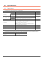
5.1
Specifications................................................................................................................................... 5 - 2
5.1.1 Specifications ....................................................................................................................... 5 - 2
5.1.2 Mail send enabled range ...................................................................................................... 5 - 3
5.2
System Configuration ...................................................................................................................... 5 - 4
5.3
Setting Method................................................................................................................................. 5 - 5
5.4
Mail Send Examples ........................................................................................................................ 5 - 6
5.5
Examples of Use.............................................................................................................................. 5 - 7
5.6
Precautions...................................................................................................................................... 5 - 8
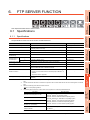
6. FTP SERVER FUNCTION
6.1
Specifications................................................................................................................................... 6 - 1
6.1.1 Specifications ....................................................................................................................... 6 - 1
6.1.2 Accessible file range............................................................................................................. 6 - 2
6.2
System Configuration ...................................................................................................................... 6 - 3
6.3
Setting Method................................................................................................................................. 6 - 4
6.4
Operation on FTP Client Side.......................................................................................................... 6 - 5
6.4.1 Input command at FTP client................................................................................................ 6 - 5
6.4.2 File specifying method .......................................................................................................... 6 - 6
6.4.3 Checking the line connection status ..................................................................................... 6 - 8
6.4.4 Line disconnection ................................................................................................................ 6 - 9
6.5
Example of Use ............................................................................................................................. 6 - 10
6.6
Precautions.................................................................................................................................... 6 - 14
7. FILE TRANSFER FUNCTION (FTP CLIENT)
7.1
Specifications................................................................................................................................... 7 - 1
7.1.1 Specifications ....................................................................................................................... 7 - 1
7.1.2 Accessible file range............................................................................................................. 7 - 2
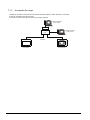
7.2
System Configuration ...................................................................................................................... 7 - 3
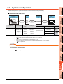
7.3
Setting Method................................................................................................................................. 7 - 4
7.3.1 GOT (FTP client) setting....................................................................................................... 7 - 4
7.3.2 FTP server setting .............................................................................................................. 7 - 12
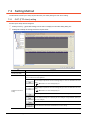
7.4
Confirmation of Processing Status ................................................................................................ 7 - 13
7.5
Examples of Use............................................................................................................................ 7 - 14
7.6
Precautions.................................................................................................................................... 7 - 16
8. TROUBLESHOOTING
8.1
Troubleshooting Common to Gateway Functions............................................................................ 8 - 1
8.2
Gateway Information........................................................................................................................ 8 - 2
8.3
Server and Client Functions ............................................................................................................ 8 - 4
8.3.1 Error codes and error messages .......................................................................................... 8 - 4
8.3.2 Troubleshooting .................................................................................................................... 8 - 5
8.4
Mail Send Function .......................................................................................................................... 8 - 6
8.4.1 Error codes and error messages .......................................................................................... 8 - 6
8.4.2 Troubleshooting .................................................................................................................... 8 - 6
8.5
FTP Server Function........................................................................................................................ 8 - 7
A-3
8.5.1
8.5.2
8.6
Error codes and error messages .......................................................................................... 8 - 7
Troubleshooting .................................................................................................................... 8 - 8
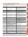
File Transfer Function (FTP Client) ................................................................................................. 8 - 9
8.6.1 Error codes and error messages .......................................................................................... 8 - 9
8.6.2 Troubleshooting .................................................................................................................. 8 - 10
INDEX
REVISIONS
A-4
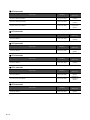
MANUALS
The following table lists the manual relevant to this product.
Refer to each manual for any purpose.
Screen creation software manuals
Manual Name
Packaging
GT Works3 Version1 Installation Procedure Manual
Enclosed in product
GT Designer3 Version1 Screen Design Manual (Fundamentals) 1/2, 2/2
Stored in CD-ROM
GT Designer3 Version1 Screen Design Manual (Functions) 1/2, 2/2
Stored in CD-ROM
GT Simulator3 Version1 Operating Manual for GT Works3
Stored in CD-ROM
GT Converter2 Version3 Operating Manual for GT Works3
Stored in CD-ROM
Manual Number
(Model code)
SH-080866ENG
(1D7MB9)
SH-080867ENG
(1D7MC1)
SH-080861ENG
(1D7MB1)
SH-080862ENG
(1D7MB2)
Connection manuals
Manual Name
Packaging
Manual Number
(Model code)
GOT1000 Series Connection Manual (Mitsubishi Products) for GT Works3
Stored in CD-ROM
SH-080868ENG
(1D7MC2)
GOT1000 Series Connection Manual (Non-Mitsubishi Products 1) for GT Works3
Stored in CD-ROM
SH-080869ENG
(1D7MC3)
GOT1000 Series Connection Manual (Non-Mitsubishi Products 2) for GT Works3
Stored in CD-ROM
SH-080870ENG
(1D7MC4)
GOT1000 Series Connection Manual (Microcomputer, MODBUS Products, Peripherals) for GT
Works3
Stored in CD-ROM
SH-080871ENG
(1D7MC5)
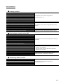
Extended and option function manuals
Manual Name
Packaging
Manual Number
(Model code)
GOT1000 Series Gateway Functions Manual for GT Works3
Stored in CD-ROM
SH-080858ENG
(1D7MA7)
GOT1000 Series MES Interface Function Manual for GT Works3
Stored in CD-ROM
SH-080859ENG
(1D7MA8)
GOT1000 Series User's Manual (Extended Functions, Option Functions) for GT Works3
Stored in CD-ROM
SH-080863ENG
(1D7MB3)
GT SoftGOT1000 manuals
Manual Name
GT SoftGOT1000 Version3 Operating Manual for GT Works3
Packaging
Stored in CD-ROM
Manual Number
(Model code)
SH-080860ENG
(1D7MA9)
A-5
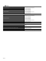
GT16 manuals
Manual Name
Packaging
Manual Number
(Model code)
GT16 User's Manual (Hardware)
Stored in CD-ROM
SH-080928ENG
(1D7MD3)
GT16 User's Manual (Basic Utility)
Stored in CD-ROM
SH-080929ENG
(1D7MD4)
GT16 Handy GOT User's Manual
Stored in CD-ROM
JY997D41201
JY997D41202
(09R821)
GT15 manuals
Manual Name
GT15 User's Manual
Packaging
Stored in CD-ROM
Manual Number
(Model code)
SH-080528ENG
(1D7M23)
GT14 manuals
Manual Name
GT14 User's Manual
Packaging
Stored in CD-ROM
Manual Number
(Model code)
JY997D44801
(09R823)
GT12 manuals
Manual Name
GT12 User's Manual
Packaging
Stored in CD-ROM
Manual Number
(Model code)
SH-080977ENG
(1D7ME1)
GT11 manuals
Manual Name
Packaging
Manual Number
(Model code)
GT11 User's Manual
Stored in CD-ROM
JY997D17501
(09R815)
GT11 Handy GOT User's Manual
Stored in CD-ROM
JY997D20101
JY997D20102
(09R817)
GT10 manuals
Manual Name
GT10 User's Manual
A-6
Packaging
Stored in CD-ROM
Manual Number
(Model code)
JY997D24701
(09R819)
QUICK REFERENCE
Creating a project
Obtaining the specifications and operation methods of GT Designer3
Setting available functions on GT Designer3
Creating a screen displayed on the GOT
GT Designer3 Version1 Screen Design Manual
(Fundamentals) 1/2, 2/2
Obtaining useful functions to increase efficiency of drawing
Setting details for figures and objects
Setting functions for the data collection or trigger action
GT Designer3 Version1 Screen Design Manual (Functions)
1/2, 2/2
Setting functions to use peripheral devices
Simulating a created project on a personal computer
GT Simulator3 Version1 Operating Manual for GT Works3
Connecting a controller to the GOT
Obtaining information of Mitsubishi products applicable to the GOT
Connecting Mitsubishi products to the GOT
GOT1000 Series Connection Manual (Mitsubishi Products) for
Connecting multiple controllersto one GOT (Multi-channel function)
GT Works3
Establishing communication between a personal computer and a
controller via the GOT (FA transparent function)
Obtaining information of Non-Mitsubishi products applicable to the GOT
• GOT1000 Series Connection Manual (Non-Mitsubishi
Products 1) for GT Works3
Connecting Non-Mitsubishi products to the GOT
Obtaining information of peripheral devices applicable to the GOT
Connecting peripheral devices including a barcode reader to the GOT
• GOT1000 Series Connection Manual (Non-Mitsubishi
Products 2) for GT Works3
GOT1000 Series Connection Manual (Microcomputer,
MODBUS Products, Peripherals) for GT Works3
Transferring data to the GOT
Writing data to the GOT
Reading data from the GOT
GT Designer3 Version1 Screen Design Manual
(Fundamentals) 1/2, 2/2
Verifying a editing project to a GOT project
A-7
Others
Obtaining specifications (including part names, external dimensions, and
• GT16 User's Manual (Hardware)
options) of each GOT
• GT16 Handy GOT User's Manual
• GT15 User's Manual
• GT14 User's Manual
• GT12 User's Manual
Installing the GOT
• GT11 User's Manual
• GT11 Handy GOT User's Manual
• GT10 User's Manual
• GT16 User's Manual (Basic Utility)
• GT16 Handy GOT User's Manual
• GT15 User's Manual
Operating the utility
• GT14 User's Manual
• GT12 User's Manual
• GT11 User's Manual
• GT11 Handy GOT User's Manual
• GT10 User's Manual
Configuring the gateway function
Configuring the MES interface function
Configuring the extended function and option function
Using a personal computer as the GOT
A-8
GOT1000 Series Gateway Functions Manual for GT Works3
GOT1000 Series MES Interface Function Manual for GT
Works3
GOT1000 Series User's Manual (Extended Functions, Option
Functions) for GT Works3
GT SoftGOT1000 Version3 Operating Manual for GT Works3
ABBREVIATIONS AND GENERIC TERMS
GOT
Abbreviations and generic terms
GT1695M-X
Abbreviation of GT1695M-XTBA, GT1695M-XTBD
GT1685
GT1685M-S
Abbreviation of GT1685M-STBA, GT1685M-STBD
GT1675M-S
Abbreviation of GT1675M-STBA, GT1675M-STBD
GT1675
GT1672
GT1665
GT1675M-V
Abbreviation of GT1675M-VTBA, GT1675M-VTBD
GT1675-VN
Abbreviation of GT1675-VNBA, GT1675-VNBD
GT1672-VN
Abbreviation of GT1672-VNBA, GT1672-VNBD
GT1665M-S
Abbreviation of GT1665M-STBA, GT1665M-STBD
GT1665M-V
Abbreviation of GT1665M-VTBA, GT1665M-VTBD
GT1662
GT1662-VN
Abbreviation of GT1662-VNBA, GT1662-VNBD
GT1655
GT1655-V
Abbreviation of GT1655-VTBD
Abbreviation of GT1695, GT1685, GT1675, GT1672, GT1665, GT1662, GT1655, GT16 Handy GOT
GT16
GT1595
GT1585
GT157
GT156
GOT1000
Series
Description
GT1695
GT155
GT1595-X
Abbreviation of GT1595-XTBA, GT1595-XTBD
GT1585V-S
Abbreviation of GT1585V-STBA, GT1585V-STBD
GT1585-S
Abbreviation of GT1585-STBA, GT1585-STBD
GT1575V-S
Abbreviation of GT1575V-STBA, GT1575V-STBD
GT1575-S
Abbreviation of GT1575-STBA, GT1575-STBD
GT1575-V
Abbreviation of GT1575-VTBA, GT1575-VTBD
GT1575-VN
Abbreviation of GT1575-VNBA, GT1575-VNBD
GT1572-VN
Abbreviation of GT1572-VNBA, GT1572-VNBD
GT1565-V
Abbreviation of GT1565-VTBA, GT1565-VTBD
GT1562-VN
Abbreviation of GT1562-VNBA, GT1562-VNBD
GT1555-V
Abbreviation of GT1555-VTBD
GT1555-Q
Abbreviation of GT1555-QTBD, GT1555-QSBD
GT1550-Q
Abbreviation of GT1550-QLBD
GT15
Abbreviation of GT1595, GT1585, GT157 , GT156 , GT155
GT1455-Q
Abbreviation of GT1455-QTBDE, GT1455-QTBD
GT1450-Q
Abbreviation of GT1450-QLBDE, GT1450-QLBD
GT1275
GT1275-V
Abbreviation of GT1275-VNBA, GT1275-VNBD
GT1265
GT145
GT14
Abbreviation of GT1455-Q, GT1450-Q
GT1265-V
Abbreviation of GT1265-VNBA, GT1265-VNBD
GT12
Abbreviation of GT1275, GT1265
GT115
GT1155-Q
Abbreviation of GT1155-QTBDQ, GT1155-QSBDQ, GT1155-QTBDA, GT1155-QSBDA,
GT1155-QTBD, GT1155-QSBD
GT1150-Q
Abbreviation of GT1150-QLBDQ, GT1150-QLBDA, GT1150-QLBD
GT1055-Q
Abbreviation of GT1055-QSBD
GT1050-Q
Abbreviation of GT1050-QBBD
GT1045-Q
Abbreviation of GT1045-QSBD
GT1040-Q
Abbreviation of GT1040-QBBD
GT11
GT105
GT104
Abbreviation of GT115 , GT11 Handy GOT,
GT1030
Abbreviation of GT1030-LBD, GT1030-LBD2, GT1030-LBL, GT1030-LBDW, GT1030-LBDW2,
GT1030-LBLW, GT1030-LWD, GT1030-LWD2, GT1030-LWL, GT1030-LWDW, GT1030-LWDW2,
GT1030-LWLW, GT1030-HBD, GT1030-HBD2, GT1030-HBL, GT1030-HBDW, GT1030-HBDW2,
GT1030-HBLW, GT1030-HWD, GT1030-HWD2, GT1030-HWL, GT1030-HWDW, GT1030-HWDW2,
GT1030-HWLW
GT1020
Abbreviation of GT1020-LBD, GT1020-LBD2, GT1020-LBL, GT1020-LBDW, GT1020-LBDW2,
GT1020-LBLW, GT1020-LWD, GT1020LWD2, GT1020-LWL, GT1020-LWDW, GT1020-LWDW2,
GT1020-LWLW
GT10
Abbreviation of GT105 , GT104 , GT1030, GT1020
A-9
Abbreviations and generic terms
GOT1000
Series
GT16
Handy
GOT
Handy
GOT
GT11
Handy
GOT
Description
GT1665HS-V
Abbreviation of GT1665HS-VTBD
GT1155HS-Q
Abbreviation of GT1155HS-QSBD
GT1150HS-Q
Abbreviation of GT1150HS-QLBD
GT SoftGOT1000
Abbreviation of GT SoftGOT1000
GOT900 Series
Abbreviation of GOT-A900 series, GOT-F900 series
GOT800 Series
Abbreviation of GOT-800 series
Communication unit
Abbreviations and generic terms
Description
Bus connection unit
GT15-QBUS, GT15-QBUS2, GT15-ABUS, GT15-ABUS2, GT15-75QBUSL, GT15-75QBUS2L,
GT15-75ABUSL, GT15-75ABUS2L
Serial communication unit
GT15-RS2-9P, GT15-RS4-9S, GT15-RS4-TE
RS-422 conversion unit
GT15-RS2T4-9P, GT15-RS2T4-25P
Ethernet communication unit
GT15-J71E71-100
MELSECNET/H communication unit
GT15-J71LP23-25, GT15-J71BR13
MELSECNET/10 communication unit
GT15-75J71LP23-Z*1, GT15-75J71BR13-Z*2
CC-Link IE Controller Network communication
unit
GT15-J71GP23-SX
CC-Link IE Field Network communication unit
GT15-J71GF13-T2
CC-Link communication unit
GT15-J61BT13, GT15-75J61BT13-Z*3
Interface converter unit
GT15-75IF900
Serial multi-drop connection unit
GT01-RS4-M
Connection Conversion Adapter
GT10-9PT5S
RS-232/485 signal conversion adapter
GT14-RS2T4-9P
*1
*2
*3
A9GT-QJ71LP23 + GT15-75IF900 set
A9GT-QJ71BR13 + GT15-75IF900 set
A8GT-J61BT13 + GT15-75IF900 set
Option unit
Abbreviations and generic terms
Printer unit
Video input unit
Video/RGB unit
Description
GT15-PRN
GT16M-V4, GT15V-75V4
RGB input unit
GT16M-R2, GT15V-75R1
Video/RGB input unit
GT16M-V4R1, GT15V-75V4R1
RGB output unit
GT16M-ROUT, GT15V-75ROUT
Multimedia unit
GT16M-MMR
CF card unit
GT15-CFCD
CF card extension unit*1
GT15-CFEX-C08SET
External I/O unit
GT15-DIO, GT15-DIOR
Sound output unit
GT15-SOUT
*1
A - 10
GT15-CFEX + GT15-CFEXIF + GT15-C08CF set.
Option
Abbreviations and generic terms
Memory card
CF card
SD card
Description
GT05-MEM-16MC, GT05-MEM-32MC, GT05-MEM-64MC, GT05-MEM-128MC,
GT05-MEM-256MC, GT05-MEM-512MC, GT05-MEM-1GC, GT05-MEM-2GC,
GT05-MEM-4GC, GT05-MEM-8GC, GT05-MEM-16GC
L1MEM-2GBSD, L1MEM-4GBSD
Memory card adaptor
GT05-MEM-ADPC
Option function board
GT16-MESB, GT15-FNB, GT15-QFNB, GT15-QFNB16M,
GT15-QFNB32M, GT15-QFNB48M, GT11-50FNB, GT15-MESB48M
Battery
GT15-BAT, GT11-50BAT
For GT16
GT16-90PSCB, GT16-90PSGB, GT16-90PSCW, GT16-90PSGW,
GT16-80PSCB, GT16-80PSGB, GT16-80PSCW, GT16-80PSGW,
GT16-70PSCB, GT16-70PSGB, GT16-70PSCW, GT16-70PSGW,
GT16-60PSCB, GT16-60PSGB, GT16-60PSCW, GT16-60PSGW,
GT16-50PSCB, GT16-50PSGB, GT16-50PSCW, GT16-50PSGW,
GT16-90PSCB-012, GT16-80PSCB-012, GT16-70PSCB-012,
GT16-60PSCB-012, GT16-50PSCB-012, GT16H-60PSC
For GT15
GT15-90PSCB, GT15-90PSGB, GT15-90PSCW, GT15-90PSGW,
GT15-80PSCB, GT15-80PSGB, GT15-80PSCW, GT15-80PSGW,
GT15-70PSCB, GT15-70PSGB, GT15-70PSCW, GT15-70PSGW,
GT15-60PSCB, GT15-60PSGB, GT15-60PSCW, GT15-60PSGW,
GT15-50PSCB, GT15-50PSGB, GT15-50PSCW, GT15-50PSGW
Protective Sheet
For GT14
GT14-50PSCB, GT14-50PSGB, GT14-50PSCW, GT14-50PSGW
For GT12
GT11-70PSCB, GT11-65PSCB
For GT11
GT11-50PSCB, GT11-50PSGB, GT11-50PSCW, GT11-50PSGW,
GT11H-50PSC
For GT10
GT10-50PSCB, GT10-50PSGB, GT10-50PSCW, GT10-50PSGW,
GT10-40PSCB, GT10-40PSGB, GT10-40PSCW, GT10-40PSGW,
GT10-30PSCB, GT10-30PSGB, GT10-30PSCW, GT10-30PSGW,
GT10-20PSCB, GT10-20PSGB, GT10-20PSCW, GT10-20PSGW
Protective cover for oil
GT05-90PCO, GT05-80PCO, GT05-70PCO, GT05-60PCO, GT05-50PCO,
GT16-50PCO, GT10-40PCO, GT10-30PCO, GT10-20PCO
USB environmental protection cover
GT16-UCOV, GT16-50UCOV, GT15-UCOV, GT14-50UCOV, GT11-50UCOV
Stand
GT15-90STAND, GT15-80STAND, GT15-70STAND, A9GT-50STAND, GT05-50STAND
Attachment
GT15-70ATT-98, GT15-70ATT-87, GT15-60ATT-97, GT15-60ATT-96,
GT15-60ATT-87, GT15-60ATT-77, GT15-50ATT-95W, GT15-50ATT-85
Backlight
GT16-90XLTT, GT16-80SLTT, GT16-70SLTT, GT16-70VLTT, GT16-70VLTTA, GT16-70VLTN,
GT16-60SLTT, GT16-60VLTT, GT16-60VLTN, GT15-90XLTT, GT15-80SLTT, GT15-70SLTT,
GT15-70VLTT, GT15-70VLTN, GT15-60VLTT, GT15-60VLTN
Multi-color display board
GT15-XHNB, GT15-VHNB
Connector conversion box
GT11H-CNB-37S, GT16H-CNB-42S
Emergency stop sw guard cover
GT11H-50ESCOV, GT16H-60ESCOV
Memory loader
GT10-LDR
Memory board
GT10-50FMB
Panel-mounted USB port extension
GT14-C10EXUSB-4S, GT10-C10EXUSB-5S
A - 11
Software
Abbreviations and generic terms
Description
GT Works3
Abbreviation of the SW DNC-GTWK3-E and SW DNC-GTWK3-EA
GT Designer3
Abbreviation of screen drawing software GT Designer3 for GOT1000 series
GT Simulator3
Abbreviation of screen simulator GT Simulator3 for GOT1000/GOT900 series
GT SoftGOT1000
Abbreviation of monitoring software GT SoftGOT1000
GT Converter2
Abbreviation of data conversion software GT Converter2 for GOT1000/GOT900 series
GT Designer2 Classic
Abbreviation of screen drawing software GT Designer2 Classic for GOT900 series
GT Designer2
Abbreviation of screen drawing software GT Designer2 for GOT1000/GOT900 series
iQ Works
Abbreviation of iQ Platform compatible engineering environment MELSOFT iQ Works
MELSOFT Navigator
Generic term for integrated development environment software included in the SW DNC-IQWK (iQ
Platform compatible engineering environment MELSOFT iQ Works)
GX Works2
Abbreviation of SW DNC-GXW2-E and SW DNC-GXW2-EA type programmable controller
engineering software
GX Simulator2
Abbreviation of GX Works2 with the simulation function
GX Simulator
Abbreviation of SW D5C-LLT-E(-EV) type ladder logic test tool function software packages
(SW5D5C-LLT (-EV) or later versions)
GX Developer
Abbreviation of SW D5C-GPPW-E(-EV)/SW D5F-GPPW-E type software package
GX LogViewer
Abbreviation of SW DNN-VIEWER-E type software package
PX Developer
Abbreviation of SW D5C-FBDQ-E type FBD software package for process control
MT Works2
Abbreviation of motion controller engineering environment MELSOFT MT Works2
(SW DNC-MTW2-E)
MT Developer
Abbreviation of SW RNC-GSV type integrated start-up support software for motion controller Q series
MR Configurator2
Abbreviation of SW DNC-MRC2-E type Servo Configuration Software
MR Configurator
Abbreviation of MRZJW -SETUP E type Servo Configuration Software
FR Configurator
Abbreviation of Inverter Setup Software (FR-SW -SETUP-WE)
NC Configurator
FX Configurator-FP
FX3U-ENET-L Configuration tool
Abbreviation of CNC parameter setting support tool NC Configurator
Abbreviation of parameter setting, monitoring, and testing software packages for FX3U-20SSC-H
(SW D5C-FXSSC-E)
Abbreviation of FX3U-ENET-L type Ethernet module setting software (SW1D5-FXENETL-E)
RT ToolBox2
Abbreviation of robot program creation software (3D-11C-WINE)
MX Component
Abbreviation of MX Component Version
(SW D5C-ACT-E, SW D5C-ACT-EA)
MX Sheet
Abbreviation of MX Sheet Version
LCPU Logging Configuration Tool
Abbreviation of LCPU Logging Configuration Tool (SW1DNN-LLUTL-E)
(SW D5C-SHEET-E, SW D5C-SHEET-EA)
License key (for GT SoftGOT1000)
Abbreviations and generic terms
License
A - 12
Description
GT15-SGTKEY-U, GT15-SGTKEY-P
Others
Abbreviations and generic terms
Description
IAI
Abbreviation of IAI Corporation
AZBIL
Abbreviation of Azbil Corporation (former Yamatake Corporation)
OMRON
Abbreviation of OMRON Corporation
KEYENCE
Abbreviation of KEYENCE CORPORATION
KOYO EI
Abbreviation of KOYO ELECTRONICS INDUSTRIES CO., LTD.
SHARP
Abbreviation of Sharp Manufacturing Systems Corporation
JTEKT
Abbreviation of JTEKT Corporation
SHINKO
Abbreviation of Shinko Technos Co., Ltd.
CHINO
Abbreviation of CHINO CORPORATION
TOSHIBA
Abbreviation of TOSHIBA CORPORATION
TOSHIBA MACHINE
Abbreviation of TOSHIBA MACHINE CO., LTD.
HITACHI IES
Abbreviation of Hitachi Industrial Equipment Systems Co., Ltd.
HITACHI
Abbreviation of Hitachi, Ltd.
FUJI
Abbreviation of FUJI ELECTRIC CO., LTD.
PANASONIC
Abbreviation of Panasonic Corporation
PANASONIC INDUSTRIAL DEVICES SUNX
Abbreviation of Panasonic Industrial Devices SUNX Co., Ltd.
YASKAWA
Abbreviation of YASKAWA Electric Corporation
YOKOGAWA
Abbreviation of Yokogawa Electric Corporation
ALLEN-BRADLEY
Abbreviation of Allen-Bradley products manufactured by Rockwell Automation, Inc.
GE
Abbreviation of GE Intelligent Platforms
LS IS
Abbreviation of LS Industrial Systems Co., Ltd.
SCHNEIDER
Abbreviation of Schneider Electric SA
SICK
Abbreviation of SICK AG
SIEMENS
Abbreviation of Siemens AG
RKC
Abbreviation of RKC INSTRUMENT INC.
HIRATA
Abbreviation of Hirata Corporation
MURATEC
Abbreviation of Muratec products manufactured by Muratec Automation Co., Ltd.
PLC
Abbreviation of programmable controller
Temperature controller
Generic term for temperature controller manufactured by each corporation
Indicating controller
Generic term for indicating controller manufactured by each corporation
Control equipment
Generic term for control equipment manufactured by each corporation
CHINO controller
Abbreviation of indicating controller manufactured by CHINO CORPORATION
PC CPU module
Abbreviation of PC CPU Unit manufactured by CONTEC CO., LTD
GOT (server)
Abbreviation of GOTs that use the server function
GOT (client)
Abbreviation of GOTs that use the client function
Windows font
Abbreviation of TrueType font and OpenType font available for Windows
(Differs from the True Type fonts settable with GT Designer3)
Intelligent function module
Indicates the modules other than the PLC CPU, power supply module and I/O module that are mounted
to the base unit
MODBUS/RTU
Generic term for the protocol designed to use MODBUS protocol messages on a serial
communication
MODBUS/TCP
Generic term for the protocol designed to use MODBUS protocol messages on a TCP/IP network
A - 13
HOW TO READ THIS MANUAL
Following symbols are used in this manual.
[ ] : Shows the setting item displayed on
the software screen or the GOT
screen.
Refers to information
required for operation.
Refers to information
useful for operation.
Shows a chapter, section, relevant
manual, or others of relevant information.
Shows the operation steps.
Operate the steps from the step 1.
*Since the above page was created for explanation purpose, it differs from the actual page.
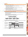
ARROW SYMBOLS USED IN ILLUSTRATIONS
Arrow symbols used in the illustrations in this manual indicate the type of communications as below:
Symbol
Description
Indicates communications in which a GOT monitors the controllers.
Indicates communications in the communication format of individual PLC makers.
Indicates communications that uses the server and client functions.
A - 14
1
OVERVIEW
OVERVIEW
1.
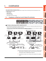
This manual explains the gateway functions.
The gateway functions include the functions below to support remote monitoring and remote maintenance of the
production site from the office.
• Server function
• Client function
• Mail send function
• FTP server function
• File transfer function (FTP client)
SYSTEM
CONFIGURATION
2
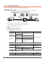
1.1 Features of Server and Client Functions
GENERAL PROCEDURE
TO BE FOLLOWED FOR
USING
3
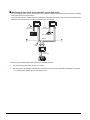
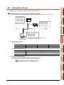
By monitoring the GOTs (server), the personal computer (MX Component) can indirectly read/write data from/to the
devices of the controllers being monitored by the GOTs.
The server function enables data to be read/written with only the MX Component even if the controller of a different
maker is monitored, and the communication method is standardized to Ethernet.
Previously....
When server function is used....
RS-232
communication
RS-422
communication
RS-422
communication
RS-232
communication
Server
MAIL SEND
FUNCTION
RS-422
communication
5
Server
Server
2.
SERVER AND
CLIENT FUNCTIONS
4
Collection of data by personal computer (server)
RS-422
communication
6
Mitsubishi PLC
Microcomputer board
Company A PLC
Microcomputer
board
Communications are made
with the personal computers in respective
communication methods of
respective companies.
FTP SERVER
FUNCTION
Ethernet
Communication is possible
only by Ethernet.
Install peripheral software
programs of various companies.
Necessary software is MX
Component only.
Client
Mitsubishi Company
A
Microcomputer
board
1.
MX Component
<Processing when writing data from a personal computer to controller devices>
1.
2.
Data is written to the gateway device of the GOT (server) by running the
user program, which is created by MX Component.
The data is then written to the controller device assigned to the gateway
device.
1.1 Features of Server and Client Functions
1-1
7
FILE TRANSFER
FUNCTION
(FTP CLIENT)
Company A PLC
8
TROUBLE
SHOOTING
Mitsubishi PLC
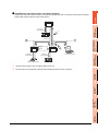
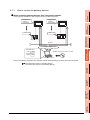
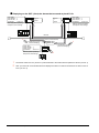
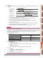
Monitoring of other GOTs from client GOT (server and client)
By monitoring the GOTs (server), the GOT (client) can indirectly read/write data from/to the devices of the controllers
being monitored by the GOTs (server).
Use of the client function enables data to be read/written indirectly from/to the PLC CPUs of various makers that are
different from the maker of the controller connected to the GOT (client).
1.
Server
RS-232
communication
Server
RS-422
communication
Company A PLC
Microcomputer board
Ethernet
2.
Client
RS-422
communication
Mitsubishi PLC
<Processing when reading data by GOT (client) from controller devices>
1.
2.
1-2
The GOT (server) monitors the devices of controller.
The GOT (client) can indirectly read data from the devices of the controller, monitored as explained in procedure
1., by monitoring the gateway device of the GOT (server).
1.1 Features of Server and Client Functions
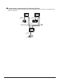
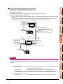
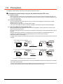
Setting of the server and client functions to a single GOT enables the GOT to send data to the personal computer
(client) while collecting data from other GOT (server).
GOT 1)
Server
SYSTEM
CONFIGURATION
2
RS-232
communication
1.
Company A PLC
3
Server
+
Client
2.
GENERAL PROCEDURE
TO BE FOLLOWED FOR
USING
Ethernet
Client
Client
4
GOT 2)
Microcomputer board
Personal computer
RS-422
communication
SERVER AND
CLIENT FUNCTIONS
RS-422
communication
OVERVIEW
1
Simultaneous use of the server and client functions
Mitsubishi PLC
Using the client function, GOT 2) collects data from GOT 1).
2.
The client GOT or the personal computer sends read/write request to GOT 2) (server).
5
MAIL SEND
FUNCTION
1.
FTP SERVER
FUNCTION
6
FILE TRANSFER
FUNCTION
(FTP CLIENT)
7
TROUBLE
SHOOTING
8
1.1 Features of Server and Client Functions
1-3
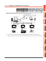
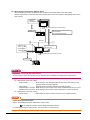
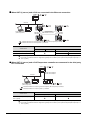
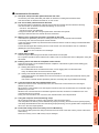
Communication enabled between GOT1000 and GOT-A900
In the system configured using GOT-A900s, it is possible to add a GOT1000 to the system or also replace a GOTA900 with a GOT1000.
GOT1000
GOT-A900
RS-422
communication
RS-232
communication
Mitsubishi PLC
Company A PLC
Ethernet
GOT-A900
RS-422
communication
Microcomputer board
1-4
1.1 Features of Server and Client Functions
1
OVERVIEW
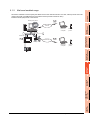
1.2 Features of Mail Send Function
Alarm history display function
Sends the alarm occurrence or recovery information
Intranet mail server
3
Personal
computer
RS-422
communication
1.
Cellular
phone
Ethernet
Mail send
function
RS-232
communication
4
Mail send
function
SERVER AND
CLIENT FUNCTIONS
Mail send
function
GENERAL PROCEDURE
TO BE FOLLOWED FOR
USING
Internet
2.
SYSTEM
CONFIGURATION
2
Using the alarm history display function, you can send the occurrence or recovery information of an error to a computer
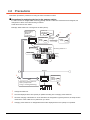
or cellular phone by mail at the time of the occurance or the recovery from an error.
RS-422
communication
5
Company A PLC
Microcomputer board
1.
The GOT sends the mail send request to the intranet mail server using the alarm history display function.
2.
In response to the request sent from the GOT, the intranet mail server sends mail to a computer or cellular phone.
MAIL SEND
FUNCTION
Mitsubishi PLC
FTP SERVER
FUNCTION
6
FILE TRANSFER
FUNCTION
(FTP CLIENT)
7
TROUBLE
SHOOTING
8
1.2 Features of Mail Send Function
1-5
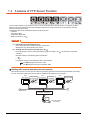
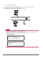
1.3 Features of FTP Server Function
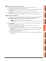
The FTP server function uses the GOT as an FTP server, and reads files from/writes files to an external FTP client.
Files such as resource data can be read from/written to GOT (FTP server) via Ethernet, by an operation from the
personal computer (FTP client).
The following files can be read/written by the FTP server function.
• CSV files
• Unicode text files
• Image data (JPEG files)
• Binary format files (*.G1 )
POINT
(1) Data which cannot be written to GOT
Do not write CSV files or Unicode text files into the GOT.
Writing them may cause failure in the monitor.
(2) Sending and receiving binary format files (*.G1
)
By using gateway common control (GS400.b8), binary format files (*.G1
computer.
Note that reading of the following files is not allowed.
• *.G1
• *.G1D
For gateway common control (GS400), refer to the following.
) can be read to a personal
6.4 Specifying the file name to read
8.2 Gateway function error information table
Reading GOT resource data with personal computer
Files stored in the GOT such as resource data can be read by operations from the personal computer (FTP client).
This can be used for reading the resource data of multiple GOTs via Ethernet, for example.
GOT
(FTP server)
GOT
(FTP server)
Alarm history
file acquisition
Memory card
Ethernet
Hard copy
acquisition
GOT
(FTP server)
Memory card
Acquire various data files
from GOT (FTP server)
Personal computer
(FTP client)
1-6
1.3 Features of FTP Server Function
Recipe update
Memory card
1
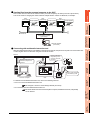
Sending files from the personal computer to the GOT
GOT
(FTP server) Recipe update
GOT
(FTP server)
Recipe update
GOT
(FTP server)
OVERVIEW
Files such as resource data can be written from the personal computer (FTP client) to the GOT (FTP server).
This can be used for changing the resource data of multiple GOTs in a batch via Ethernet, for example.
Recipe update
2
SYSTEM
CONFIGURATION
Memory card
Send the recipe file from
the personal computer
(FTP client).
3
GENERAL PROCEDURE
TO BE FOLLOWED FOR
USING
Ethernet
Memory card
Personal computer
(FTP client)
Connecting with multimedia interaction tool
With the multimedia interaction tool installed on the personal computer, the personal computer can receive video files
or alarm log files sent from the GOT using the FTP server function.
Ethernet
Sending video files to the
personal computer via
Ethernet
Storing video files
temporarily in the
memory card with
the GOT
3
4
SERVER AND
CLIENT FUNCTIONS
Memory card
5
2
1
MAIL SEND
FUNCTION
Memory card
Camcorder
Storing video images
in the memory card
6
Multimedia unit
FTP SERVER
FUNCTION
Personal computer
GOT
For details of the multimedia interaction tool, refer to the following manuals.
• For how to use the multimedia interaction tool
GT Designer 3 Version1 Screen Design Manual (Functions)
7
• For connection with the multimedia interaction tool
FILE TRANSFER
FUNCTION
(FTP CLIENT)
GOT1000 Series Connection Manual (Microcomputer, MODBUS Products, Peripherals)
for GT Works3
TROUBLE
SHOOTING
8
1.3 Features of FTP Server Function
1-7
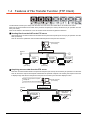
1.4 Features of File Transfer Function (FTP Client)
The file transfer function (FTP client) uses the GOT as an FTP client, and writes files to an external FTP server.
Files such as resource data can be written to the personal computer (FTP server) via Ethernet, by an operation from the
GOT (FTP client).
Files can be written to the maximum of 16 FTP servers which have been registered in advance.
Sending files from the GOT to the FTP server
Various files such as resource data can be written into the personal computer (FTP server) by an operation from the
GOT (FTP client).
This can be used to update the resource data inside the personal computer from the GOT.
Personal computer
(FTP server)
Writing into the FTP server
Ethernet
Log file
collection
Hard copy
acquisition
Memory card
Memory card
Memory card
GOT
(FTP client)
GOT
(FTP client)
Alarm log file
conversion
GOT
(FTP client)
Acquiring resource data from the FTP server
Files such as resource data stored in the personal computer (FTP server) can be read by an operation from the GOT.
This can be used to acquire the recipe file created with the personal computer to be used by the recipe function and
to display image data saved in the personal computer on the GOT by the document display function.
Saving in the personal computer
・Recipe file
・Image data for document display
Ethernet
Personal computer
(FTP server)
Acquiring files from
the FTP server
Image file for
document
display acquisition
Recipe file
acquisition
Memory card
Memory card
GOT
(FTP client)
1-8
1.4 Features of File Transfer Function (FTP Client)
GOT
(FTP client)
1
SYSTEM CONFIGURATION
OVERVIEW
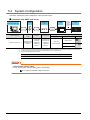
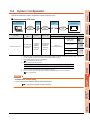
2.
This chapter describes the system configuration of the gateway system.
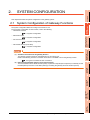
2.1 System Configuration of Gateway Functions
SYSTEM
CONFIGURATION
2
The system configuration differs according to the function to use.
For the system configuration of each function, refer to the following.
• Client/server function
4.3 System Configuration
• Mail send function
3
GENERAL PROCEDURE
TO BE FOLLOWED FOR
USING
5.2 System Configuration
• FTP server function
6.2 System Configuration
• File transfer function (FTP client)
7.2 System Configuration
4
SERVER AND
CLIENT FUNCTIONS
POINT
(1) Available connections for the gateway function
The gateway function cannot be used depending on connection type.
Refer to the following maual for connection forms which is available / N/A for the gateway function.
2.2 Types of Controller to GOT Connection
5
MAIL SEND
FUNCTION
(2) Data accessing method using the server/client function
The server/client function allows the GOT (client) or personal computer (MX Component) to indirectly access
the data (device) of the PLC or the GOT (client) by accessing the gateway device of the GOT (server).
FTP SERVER
FUNCTION
6
FILE TRANSFER
FUNCTION
(FTP CLIENT)
7
TROUBLE
SHOOTING
8
2.1 System Configuration of Gateway Functions
2-1
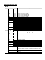
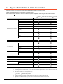
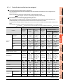
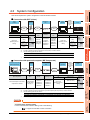
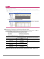
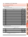
2.2 Types of Controller to GOT Connection
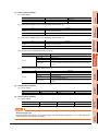
GOTs that can use the server/client function are indicated below based on connection forms.
(Other gateway functions are not restricted by connection forms.)
Refer to the following manuals for information about the system configuration when using the server/client function.
GOT1000 Series Connection Manual for GT Works3 and a controller used
: Usable
Connection
: Usable under some restrictions
GT16/GT15/GT14
: Unusable
GT12
Bus connection
Direct CPU connection
Computer link connection
Ethernet connection
MELSECNET/H connection (PLC to PLC
network)
MITSUBISHI PLC connection*5
MELSECNET/10 connection (PLC to PLC
network)
*1
CC-Link IE Controller Network connection
CC-Link IE Field Network connection
CC-Link connection (Intelligent device
station)
*2*3
CC-Link connection (Via G4)
Inverter connection
Servo amplifier connection
Robot controller connection*6
Serial connection
Ethernet connection
CNC
connection*7
MELSECNET/10 connection (PLC to PLC
network)
*1
CC-Link connection (Intelligent device
station)
*2
Serial connection
*4
Third party PLC connection
Ethernet connection
Third party safety controller connection
Third party servo amplifier connection
Third party robot controller connection
Third party temperature controller connection
*4
Serial connection
Microcomputer connection
Ethernet connection
MODBUS
/RTU connection
MODBUS /TCP connection
*1
*3
*4
When using the MELSECNET/10 connection, use a MELSECNET/H communication unit. The MELSECNET/10 communication
unit is inapplicable.
When using the CC-Link communication, use a CC-Link communication unit (GT15-J61BT13). The CC-Link communication unit
(GT15-75J61BR13-Z) is inapplicable.
The GT16 is applicable to the CC-Link (ID) Ver.2 only.
When connected to either of the following equipment, the server function and client function cannot be used.
*5
*6
*7
JTEKT PLC
SHINKO indicating controller
Including connection to the motion controller CPU (Q series and A series), CNC C70, and CRnQ-700
Applicable to the CRnD-700 only. For the CRnQ-700, refer to the above Mitsubishi PLC connection.
Applicable to the MELDAS C6/C64 only. For the CNC C70, refer to the above Mitsubishi PLC connection.
*2
2-2
2.2 Types of Controller to GOT Connection
1
OVERVIEW
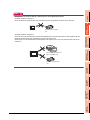
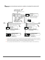
HINT
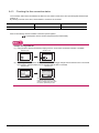
Examples of connections that do not allow the use of the gateway functions
(Example 1) When using GT11
Since the Ethernet communication unit cannot be mounted, the gateway functions cannot be used.
GT11
SYSTEM
CONFIGURATION
2
Ethernet communication
unit
(Example 2) When using GT15
Since the CC-Link communication unit (GT15-75J61BR13-Z) cannot be mounted to a GOT together with the
Ethernet communication unit, the gateway functions cannot be used.
When using CC-Link and Ethernet communication units together, use a CC-Link communication unit (GT15J61BT13).
GENERAL PROCEDURE
TO BE FOLLOWED FOR
USING
3
SERVER AND
CLIENT FUNCTIONS
4
CC-Link communication unit
(GT15-75J61BR13-Z)
GT15
5
MAIL SEND
FUNCTION
Ethernet communication
unit
FTP SERVER
FUNCTION
6
FILE TRANSFER
FUNCTION
(FTP CLIENT)
7
TROUBLE
SHOOTING
8
2.2 Types of Controller to GOT Connection
2-3
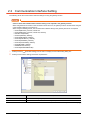
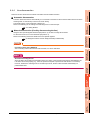
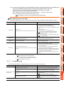
2.3 Communication Interface Setting
The following shows the communication interface settings for using the gateway function.
POINT
Cases in which the communication interface setting is not required in the gateway function
When using Ethernet connection in the connection of such as PLCs, the gateway function communicates using the
communication settings of such as PLCs.
When using the following drivers, the communication interface setting in the gateway function is not required.
• Ethernet(MELSEC), Q17nNC, CRnD-700
• Ethernet(MELSEC), Q17nNC, CRnD-700, Gateway
• MELSEC-FX(Ethernet)
• Ethernet(OMRON), Gateway
• Ethernet(KEYENCE), Gateway
• Ethernet(TOSHIBA nv), Gateway
• Ethernet(YASKAWA), Gateway
• Ethernet(YOKOGAWA), Gateway
• EtherNet/IP(AB), Gateway
• MODBUS/TCP, Gateway
• Ethernet(MICROCOMPUTER)
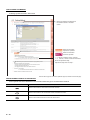
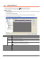
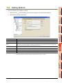
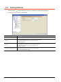
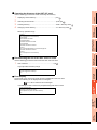
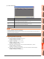
1.
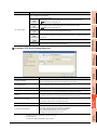
Select [Common]
2.
Select [Communication setting] and set the required items.
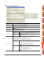
[Controller Setting] from the menu to display the Controller Setting dialog box.
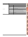
Item
Description
Use the function of Gateway
Check this item when using the gateway function.
I/F
Select the GOT communication interface to use in the gateway function.
(Continued to next page)
2-4
2.3 Communication Interface Setting
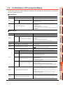
1
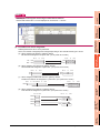
Item
Description
Set the details of the communication method.
Set the station No. of the GOT.
GOT IP Address
Set the IP address of the GOT.
Subnet Mask
Set the subnet mask for the sub network. (Only for connection via router)
If the sub network is not used, the default value is set. (Default: 255.255.255.0)
Default Gateway
Set the router address of the default gateway where the GOT is connected.
(Only for connection via router)
Ethernet Download Port No.
Set the GOT port No. for Ethernet download.
GOT Communication Port
No.
Set the GOT port No. for the connection with the Ethernet module.
Retry (Times)
Set the number of retries to be performed when a communication timeout occurs.
When receiving no response after retries, the communication times out.
Startup Time (Sec)
Specify the time period from the GOT startup until GOT starts the communication
with the PLC CPU.
Timeout Time (Sec)
Set the time period for a communication to time out.
Delay Time (x10ms)
Set the delay time for reducing the load of the network/destination PLC.
OVERVIEW
Set the network No. of the GOT.
GOT PLC No.
SYSTEM
CONFIGURATION
2
GENERAL PROCEDURE
TO BE FOLLOWED FOR
USING
3
SERVER AND
CLIENT FUNCTIONS
4
MAIL SEND
FUNCTION
5
FTP SERVER
FUNCTION
6
FILE TRANSFER
FUNCTION
(FTP CLIENT)
7
8
TROUBLE
SHOOTING
Detail Setting
GOT NET No.
2.3 Communication Interface Setting
2-5
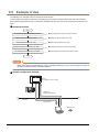
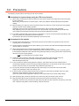
2.4 Precautions for System Configuration
Connection to the intranet
To secure the safety of the system against illegal access when connecting the system to the intranet, consult the
network access provider or network administrator (person who does network planning, IP address management,
etc.).
We have no liability for any system problems that occur at the time of connection to the intranet.
Access delay measures
Connection of multiple pieces of network equipment (including GOTs) to the same segment may degrade the
performance of communications between a GOT and a PLC CPU due to increased network load.
Communication performance may be improved by taking the measures below.
• Using a switching hub
• Decreasing the number of device monitored by the GOT
Use of firewalls
If the firewall shuts off communication of the gateway function, it is necessary to change the port No. of the firewall.
To secure the safety of the system against illegal access when changing the port No. of the firewall, consult the
network access provider or network administrator (person who does network planning, IP address management,
etc.).
We have no liability for any system problems that occur at the time of changing the port No.
2-6
2.4 Precautions for System Configuration
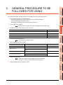
1
GENERAL PROCEDURE TO BE
FOLLOWED FOR USING
OVERVIEW
3.
2
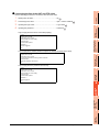
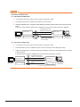
This chapter describes the general procedure to be followed for using the gateway functions.
2.
Examine the configuration of the whole system.
• Connection structure of the whole system such as the controllers and GOTs
• Controller setting (device assignment, etc.)
• GOT setting (IP address, network number, station number, etc.)
SYSTEM
CONFIGURATION
1.
Connect GOT and controllers.
3
Establish a system for the gateway function to be used.
Function
4.
Reference
Server/client function
4.3
Mail send function
5.2
FTP server function
6.2
File transfer function (FTP client)
7.2
4
SERVER AND
CLIENT FUNCTIONS
3.
GENERAL PROCEDURE
TO BE FOLLOWED FOR
USING
GOT1000 Series Connection Manual for GT Works3 and a controller used
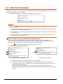
Set the communication interface.
2.3 Communication Interface Setting
5.
Set the gateway functions to be used.
Function
Server/client function
Setting
Make server and client settings on GT Designer3.
5
Reference
4.4
Set the send destination and SMTP server in the mail send
setting.
5.3
FTP server function
Configure the FTP server setting with GT Designer3.
6.3
File transfer function (FTP client)
Configure the file transfer setting with GT Designer3.
6
7.3
Prepare the project data.
FTP SERVER
FUNCTION
6.
Configure the connected FTP server setting with GT Designer3.
MAIL SEND
FUNCTION
Set the mail of each object on GT Designer3.
Mail send function
GT Designer 3 Version1 Screen Design Manual (Fundamentals)
GT Designer 3 Version1 Screen Design Manual (Functions)
7
FILE TRANSFER
FUNCTION
(FTP CLIENT)
Debug the project data by operating the GOT.
8
TROUBLE
SHOOTING
7.
3-1
3-2
1
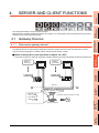
SERVER AND CLIENT FUNCTIONS
OVERVIEW
4.
This chapter describes the server and client functions.
Before using the example programs described in this chapter in an actual system, please verify that the program has no
problems in the control of the target system.
4.1 Gateway Devices
GENERAL PROCEDURE
TO BE FOLLOWED FOR
USING
3
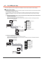
What are the gateway devices?
The gateway devices are virtual devices designed exclusively to perform the server and client functions on a GOT.
They are used by assigning the controller devices and the internal devices of a GOT.
4
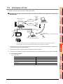
When accessing PLCs from a personal computer via a GOT
A personal computer can indirectly access the controller devices by accessing the gateway devices of GOTs (server).
• Assignment
definition
EG0=D100
Server
• Assignment
definition
EG0=TIM50
Server
SERVER AND
CLIENT FUNCTIONS
4.1.1
SYSTEM
CONFIGURATION
2
5
TIM50 : 330
MAIL SEND
FUNCTION
D100 : 250
Omron PLC
Mitsubishi PLC
6
FTP SERVER
FUNCTION
Ethernet
Access to gateway devices
Use MX Component Version 3 or later.
FILE TRANSFER
FUNCTION
(FTP CLIENT)
7
Personal computer
8
TROUBLE
SHOOTING
• Mitsubishi PLC
D100
250
• Omron PLC
TIM50
330
4.1 Gateway Devices
4-1
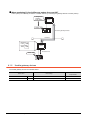
When monitoring PLCs of difference makers from one GOT
A GOT (client) can indirectly access the controller devices by accessing the gateway devices of a GOT (server).
• Assignment
definition
EG0=TIM50
Server
TIM50 : 330
Access to gateway devices
Omron PLC
Ethernet
• Mitsubishi PLC
D100
250
• Omron PLC
TIM50
330
Client
Access to PLC
D100 : 250
Mitsubishi PLC
4.1.2
Usable gateway devices
The usable gateway devices are indicated below:
Device Name
4-2
Device Number
Representation
Device Range
Word device
EG
EG0 to EG32767
Decimal
Bit device
EG
Specified bits of word devices indicated above
Decimal
4.1 Gateway Devices
4.1.3
1
How to monitor the gateway devices
OVERVIEW
When accessing gateway devices from a personal computer
Access gateway devices of a GOT using the functions of MX Component.
Server
D100 : 250
• Assignment
definition
EG0=TIM50
2
Server
SYSTEM
CONFIGURATION
• Assignment
definition
EG0=D100
TIM50 : 330
GENERAL PROCEDURE
TO BE FOLLOWED FOR
USING
3
Omron PLC
Mitsubishi PLC
Ethernet
Access to gateway devices
4
SERVER AND
CLIENT FUNCTIONS
• Mitsubishi PLC
D100
250
• Omron PLC
TIM50
330
Use MX Component Version 3 or later.
Personal computer
Refer to the following manuals for the operation method and programming procedure of the MX Component.
5
MAIL SEND
FUNCTION
MX Component Version 3 Operating Manual
MX Component Version 3 Programming Manual
FTP SERVER
FUNCTION
6
FILE TRANSFER
FUNCTION
(FTP CLIENT)
7
TROUBLE
SHOOTING
8
4.1 Gateway Devices
4-3
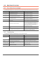
The table below shows the MX Component functions that are compatible with the GOT:
Item
Description
Open
Opens the communication line (starts communication with the GOT).
Close
Closes the communication line (ends communication with the GOT).
ReadDeviceBlock
Batch-reads data from devices.
ReadDeviceBlock2
WriteDeviceBlock
Batch-writes data to devices.
WriteDeviceBlock2
ReadDeviceRandom
ReadDeviceRandom2
WriteDeviceRandom
WriteDeviceRandom2
Randomly reads data from devices.
Randomly writes data to devices.
EntryDeviceStatus
Registers device status watching.
FreeDeviceStatus
Cancels registering device status watching.
OnDeviceStatus
Announces event.
SetDevice
Changes the device data values.
SetDevice2
GetDevice
Gets the device data values.
GetDevice2
GetCpuType
4-4
Gets the GOT model.
4.1 Gateway Devices
1
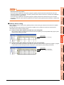
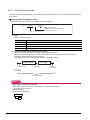
When accessing gateway devices from the GOT
OVERVIEW
Gateway devices cannot be assigned to the object functions.
For this reason, use Project script and Screen script to monitor.
Object script cannot be used.
The following explains the setting example for accessing gateway devices from a GOT.
Read the value of a gateway device of the GOT (server) to an internal device of the GOT (client) using the script
function.
By monitoring the value read to the internal device using the numerical value display function or the like, the
GOT (client) can monitor the same value as the gateway device value of the GOT (server).
• Assignment
definition
EG0=TIM50
3
TIM50 : 520
GENERAL PROCEDURE
TO BE FOLLOWED FOR
USING
Server
(
(b) Setting items of the GOT (server)
EG0 value is read to GD100 by
script function.
[w:GD100]=[1-1:w:EG0];
Omron PLC
SERVER AND
CLIENT FUNCTIONS
4
Ethernet
• Mitsubishi PLC
D100
250
• Omron PLC
520
TIM50
GOT internal device
GD100 : 520
Client
5
(a) Setting items of the GOT (client)
MAIL SEND
FUNCTION
(
2
SYSTEM
CONFIGURATION
(1) When reading a gateway device value
D100 : 250
6
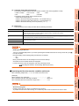
Read destination of the script function
A device of Mitsubishi Electric PLC CPU may be specified as the destination for reading out a value by the script
function.
(a) Setting items of the GOT (client)
• Script function.........................Make setting to read the gateway device value of the GOT (server) to the
internal device of the GOT (client).
• Client setting...........................Register the GOT (server) whose device value should be read.
• Numerical display 1 function...Make setting to display the device value of a Mitsubishi Electric PLC CPU.
• Numerical display 2 function...Make setting to display the internal device value of the GOT (client).
4.1 Gateway Devices
8
TROUBLE
SHOOTING
(b) Setting items of the GOT (server)
• Server setting..........................Make setting to assign a device of Omron PLC to a gateway device.
7
FILE TRANSFER
FUNCTION
(FTP CLIENT)
HINT
FTP SERVER
FUNCTION
Mitsubishi PLC
4-5
(2) When writing a value to the gateway device
Use numerical input function or the like to write a value to the internal device of the GOT (client).
Use the script function to write the value of the internal device of the GOT (client) to the gateway device of the
GOT (server).
• Assignment
definition
EG0=TIM50
Server
(
(b) Setting items of the GOT (client)
TIM50 : 520
GD100 value is written to EG0 by
script function.
[1-1:w:EG0]=[w:GD100];
Omron PLC
Ethernet
• Mitsubishi PLC
D100
250
• Omron PLC
TIM50
520
GOT internal device
GD100 : 520
Client
(
(a) Setting items of the GOT (server)
D100 : 250
Mitsubishi PLC
HINT
Destination of writing by the script function
An internal device of the GOT (server) may be specified as the destination of writing by the script function.
(a) Setting items of the GOT (client)
• Script function......................Make setting to write the internal device value of the GOT (client) to the
gateway device of the GOT (server).
• Client setting........................Register the GOT (server) where the value will be written.
• Numerical input 1 function...Make setting to input a value to the device of Mitsubishi Electric PLC CPU.
• Numerical input 2 function...Make setting to input a value to the internal device of the GOT (client).
(b) Setting items of the GOT (server)
• Server setting......................Make setting to assign a device of Omron PLC to a gateway device.
POINT
Details about the script function
Refer to the following manual for details of the script function.
GT Designer 3 Version1 Screen Design Manual (Functions)
For examples of using the script function, refer to Section 4.4 of this manual.
4-6
4.1 Gateway Devices
4.1.4
1
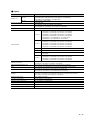
Controller devices that can be assigned
OVERVIEW
Controller devices that can be assigned
The controller devices that can be monitored by a GOT and the GOT internal devices can be assigned to the
gateway devices.
Refer to the following manual for the devices that can be monitored by a GOT.
When the following controller devices are assigned to the gateway devices, there are cases monitoring is not
possible depending on the used script function commands or MX Component functions.
To monitor such unusable devices, change them to other devices of the controller and access those devices from a
GOT.
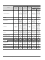
The restricted commands / functions are indicated below by controller models:
Controller
Q/L/QnACPU,
CRnD-700
ACPU
FXCPU
WSCPU
CNC
Device
specified as bit
Read Device
Block
Read Device Random
Write Device Random
Device
specified as
word
Device
specified as bit
4
(TT, TC, CT, CC,
SC, SS)
(TT, TC, CT, CC,
SC, SS)
(TN, CN, SN,
Z, BM)
(TT, TC, CT, CC,
SC, SS)
(TT, TC, CT, CC,
SC, SS)
(TN, CN, SN,
Z, BM)
(TT, TC, CT, CC)
(TT, TC, CT, CC)
(Z, V, BM)
(TT, TC, CT, CC)
(TT, TC, CT, CC)
(Z, V, BM)
(TC, CS)
(T, C)
(TC, CS)
(TS, CS)
(T, C)
(TS, CS)
(I, Q, LQ, LI)
(I, Q, LQ, LI)
(TN, CN, SN, Z,
BN)
(TN, CN, SN, Z,
BN)
(A, C0, C1, C3)
(A, C0, C1, C3)
CR, B, VB, T,
C, TC, TS,
CC, CS, CTH,
CTC, DZ, TRM)
(T, C, CTC, TC,
TS, CC, CS,
CTH, CTC, CM,
TM, VM, Z, DZ,
TRM)
(VB, T, C,
CTC, TC, TS,
CC, CS, CTH,
CTC, DZ, TRM)
(TCS)
(EB, TCS)
(TCS)
(T, C)
(T, C)
(T, C)
(I, Q, LQ, LI)
(TN, CN, SN, Z,
BN)
(TT, TC, CT, CC,
SC, SS)
(I, Q, LQ, LI)
(TT, TC, CT, CC,
SC, SS)
(TN, CN, SN, Z,
BN)
OMRON PLC
OMRON temparature controller
(A, C0, C1, C3)
(VB, T, C,
CTC, TC, TS,
CC, CS, CTH,
CTC, DZ, TRM)
KEYENCE PLC
(.., MR, LR,
(A, C0, C1, C3)
(.., MR, LR,
CR, B, VB, T,
C, TC, TS,
CC, CS, CTH,
CTC, DZ, TRM)
(T, C, CTC, TC,
TS, CC, CS,
CTH, CTC, CM,
TM, VM, Z, DZ,
TRM)
(TCS)
(EB, TCS)
(T, C)
(T, C)
KOYO EI PLC
5
6
7
(TCS)
*1
SHARP PLC
(T, C)
*1
FILE TRANSFER
FUNCTION
(FTP CLIENT)
JTEKT PLC
SHINKO indicating controller
CHINO controller
(0, 1)
Unified Controller nv
8
(XW,YW,RW,
SW,IW,QW)
TOSHIBA PLC
PROSEC T/V
(0, 1)
(Z, T, C)
(XW,YW,RW,
SW,IW,QW)
(Z, T, C)
(Continued to next page)
4.1 Gateway Devices
4-7
TROUBLE
SHOOTING
Mitsubishi
Electric
bmov, fmov
instruction
Device
specified as
word
Restricted MX Component Functions
3
SERVER AND
CLIENT FUNCTIONS
Restricted Script Function Commands
: Cannot be used
MAIL SEND
FUNCTION
: Some devices cannot be used (unusable device names are indicated in parentheses)
FTP SERVER
FUNCTION
: No restrictions
GENERAL PROCEDURE
TO BE FOLLOWED FOR
USING
Precautions for monitoring the gateway devices
SYSTEM
CONFIGURATION
2
GT Designer 3 Version1 Screen Design Manual (Fundamentals)
Restricted Script Function Commands
Controller
bmov, fmov
instruction
TOSHIBA MACHINE PLC
PANASONIC INDUSTRIAL DEVICES
SUNX PLC
HITACHI IES PLC
HITACHI PLC
FUJI PLC
Device
specified as
word
Device
specified as bit
(X, I, Y, O, R,
GR, H, J, K, T,
C, S, L, E, A)
(XW, IW, YW,
OW, RW, GW,
HW, JW, KW,
TW, CW, SW,
LW, EW, AW,
D, B, U, M,
Q, P, V)
Device
specified as
word
Device
specified as bit
(X, I, Y, O, R,
GR, H, J, K, T,
C, S, L, E, A)
(XW, IW, YW,
OW, RW, GW,
HW, JW, KW,
TW, CW, SW,
LW, EW, AW,
D, B, U, M,
Q, P, V)
(T, C)
(X, Y, L, L1, M,
D, SS, WDT,
MS, TMR, CU,
RCU, CT, R,
DIF, DFN)
(X, Y, L, L1, M,
D, SS, WDT,
MS, TMR, CU,
RCU, CT, R,
DIF, DFN)
(LLL, LML, LF,
LG)
(X, Y, R, M, A, K,
T, U, C, GL, E,
S, J, Q, LLL,
LML, LF, LG)
(BD, TS, TR,
W9, CS, CR)
(B, M, K, F, A, D,
L, T, C, BD, TS,
TR, W9, CS,
CR)
(WB, WM, WK,
WF, WA, WD,
WL, BD, TS, TR,
W9, CS, CR)
MATSUSHITA PLC
Read Device
Block
Read Device Random
Write Device Random
(T, C)
(XW, YW, RW,
MW, AW, KW,
TW, UW, CW,
GW, EW, SW,
JW, QW, TC,
TS, UC, US,
CC, CS, LLL,
LML, LF, LG)
FUJI temperature controller
Restricted MX Component Functions
(LLL, LML, LF,
LG)
(X, Y, R, M, A, K,
T, U, C, GL, E,
S, J, Q, LLL,
LML, LF, LG)
(XW, YW, RW,
MW, AW, KW,
TW, UW, CW,
GW, EW, SW,
JW, QW, TC,
TS, UC, US,
CC, CS, LLL,
LML, LF, LG)
(BD, TS, TR,
W9, CS, CR)
(B, M, K, F, A, D,
L, T, C, BD, TS,
TR, W9, CS,
CR)
(WB, WM, WK,
WF, WA, WD,
WL, BD, TS, TR,
W9, CS, CR)
(0, 1)
(0, 1)
(T, C)
(T, C)
YASKAWA PLC
AZBIL control
equipment
SDC/DMC
DMC50
YOKOGAWA PLC
YOKOGAWA PLC (MODBUS/TCP
connection)
(M, Z)
(M, TU, CU, Z)
(M, TP, TS, CP,
CS, Z)
(M, Z)
(M, TU, CU, Z)
(M, TP, TS, CP,
CS, Z)
(6)
(0, 1)
(6)
(6)
(0, 1)
(6)
YOKOGAWA temperature controller
RKC temperature controller
(0, 1)
(0, 1)
(Continued to next page)
4-8
4.1 Gateway Devices
ALLENBRADLEY PLC
MicroLogix
1000/1200/1500
series
Control/CompactLogix
Device
specified as
word
Device
specified as bit
Read Device
Block
(T, C)
(T, C)
(T, C)
(T, C, L)
(T, C, L)
(DINT, REAL)
(BOOL, DINT,
REAL)
GE PLC
Device
specified as
word
Device
specified as bit
(T, C)
(T, C)
(T, C)
(T, C, L)
(T, C, L)
(T, C, L)
(T, C, L)
(DINT, REAL)
(DINT, REAL)
(BOOL, DINT,
REAL)
(DINT, REAL)
(I, Q, M, T, S,
SA, SB, SC, G)
SICK Safety Controller
(I, Q, LQ, LI)
(I, Q, LQ, LI)
S7-300/400 series
(I, Q, M)
(IW, QW, MW)
(V, I, Q, M, SM,
T, C, S, HC)
(VW, IW, QW,
AIW, AQW, MW,
SMW, T, C, SW,
HC)
(T, C, HC)
(6)
(0, 1)
(6)
(6)
(0, 1)
(6)
SIEMENS PLC
S7-200 series
(T, C, HC)
2
(I, Q, M, T, S,
SA, SB, SC, G)
(I, Q, LQ, LI)
(I, Q, LQ, LI)
(I, Q, M)
(IW, QW, MW)
(V, I, Q, M, SM,
T, C, S, HC)
(VW, IW, QW,
AIW, AQW, MW,
SMW, T, C, SW,
HC)
(6)
(0, 1)
(6)
(6)
(0, 1)
(6)
Microcomputer
MODBUS equipment (MODBUS/RTU
connection, MODBUS/TCP connection)
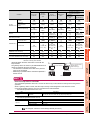
For registers (09 to E7) and file registers (1 to 7), do not make a setting that spans two blocks.
Otherwise monitoring will be disabled.
(Example) When the bmov instruction is used with the
script function
The gateway device to which TT (ALLEN-BRADLEY PLC
device) is assigned cannot be monitored.
• The devices not indicated in the table in the previous
page can be monitored.
• Monitoring is possible with the commands specified a
device as a bit.
bmove instruction of
the script function
GOT
(Client)
Mitsubishi PLC
4
5
Device TT is assigned to
gateway device.
EG0=T4:0/14(TT)
MAIL SEND
FUNCTION
*1
3
SERVER AND
CLIENT FUNCTIONS
SCHNEIDER PLC
(MODBUS/TCP connection)
OVERVIEW
SLC500
bmov, fmov
instruction
Read Device Random
Write Device Random
SYSTEM
CONFIGURATION
Controller
1
Restricted MX Component Functions
GENERAL PROCEDURE
TO BE FOLLOWED FOR
USING
Restricted Script Function Commands
GOT
(Server)
6
ALLEN-BRADLEY PLC
FTP SERVER
FUNCTION
HINT
Restricted script function commands
The commands specified a device as a word or bit device may not be executed correctly with a wrong device
specified.
When a gateway device is used, write the script correctly so that designation of the device is correct.
Commands specified a device as a word or bit device are indicated below:
• Commands specified a device as a word
Description
Applied arithmetic
operation
Function
FILE TRANSFER
FUNCTION
(FTP CLIENT)
Item
7
sin, cos, tan, asin, acos, atan, abs, log, log10, exp, ldexp, sqrt
• Commands specified a device as a bit
Item
Operator
Description
Bit device
&, |, ~, ^, <<, >>
Substitution
=
Device operation
set, rst, alt
8
TROUBLE
SHOOTING
Refer to the following manual for details of commands.
GT Designer 3 Version1 Screen Design Manual (Functions)
4.1 Gateway Devices
4-9
4.2 Specifications
4.2.1
Specifications
The specifications of the server and client functions are given below:
Item
Port number
Specifications
Server function
5011
Client function
5012, 5013
Setting Method
Fixed
Max. number of nodes
Recommended: Total number of the following nodes is 64.
• GOT (server)
• GOT (client)
• Personal computer that communicates with a GOT
–
Number of clients (GOT, personal computer) that can
access a server (GOT) simultaneously
Max. 5 units*1
–
Other node designation
IP address designation, max. 128 nodes
Gateway device
32768 points of word devices: EG0 to 32767
Compatible MX Component
MX Component Version 3 or later
Memory space used by GOT
(bytes)
*1
4.2.2
Server function
20 + 20 (Number of assigned gateway devices)
Client function
16 + 20 (Preset number of GOTs (server))
GT Designer2
–
GT Designer2
If six or more clients (GOT, personal computer) make simultaneous access to the server (GOT), processing of the script at a client
may stop.
Access range that can be monitored
When the monitoring of a controller is required via a GOT, it is possible by monitoring controller devices that are assigned
to gateway devices. (The devices of the controller on the network can be monitored by assigning the devices to gateway
devices.)
The access range that can be monitored is the same the GOT does.
Refer to the following manual for the range that a GOT can monitor.
GOT1000 Series Connection Manual (Mitsubishi Products) for GT Works3
4 - 10
4.2 Specifications
The accessible range of a PLC CPU from a GOT 1) (client) or a personal computer (MX Component) is indicated below:
1
When GOT 2) (server) and a PLC 1) are connected in the direct CPU connection or
GOT 2) (
:
1) :
OVERVIEW
computer link connection
)
Server
2
RS-232 communication/
RS-422 communication
SYSTEM
CONFIGURATION
Ethernet
Client
MELSECNET/H or like
3
GENERAL PROCEDURE
TO BE FOLLOWED FOR
USING
GOT 1)
: Indicates whether the access by personal computer (MX Component) is allowed.
1) : Indicates whether the access by GOT 1) is allowed.
Access Destination
Access Source
GOT 2) (server)
4
PLC 1), PLC 2), PLC 3), PLC 4)
Personal computer (MX Component),
GOT 1) (client)
: Can monitor a gateway device or a controller device from a personal computer (MX Component) or a GOT 1) (client).
: Can monitor a controller device that is assigned to a gateway device of GOT 2) from a personal computer (MX Component) or a
GOT 1) (client).
When GOT 2) (server) and a PLC are connected in the CC-Link connection (via G4)
GOT 2) (
:
1) :
SERVER AND
CLIENT FUNCTIONS
Personal computer
(MX Component)
5
)
MAIL SEND
FUNCTION
Server
RS-232 communication/
RS-422 communication
Ethernet
AJ65BT-G4-S3
6
Client
FTP SERVER
FUNCTION
CC-Link
Personal computer
(MX Component)
GOT 1)
7
Access Source
FILE TRANSFER
FUNCTION
(FTP CLIENT)
: Indicates whether the access by personal computer (MX Component) is allowed.
1) : Indicates whether the access by GOT 1) is allowed.
Access Destination
GOT 2) (server)
PLC 1), PLC 2), PLC 3)
Computer (MX Component),
GOT 1) (client)
8
: Can monitor a gateway device or a controller device from a personal computer (MX Component) or a GOT 1) (client).
TROUBLE
SHOOTING
: Can monitor a controller device that is assigned to a gateway device of GOT 2) from a personal computer (MX Component) or a
GOT 1) (client).
4.2 Specifications
4 - 11
When GOT 2) (server) and a PLC are connected in the Ethernet connection
2) (
:
1) :
)
Server
Ethernet
Client
Personal computer
(MX Component)
GOT 1)
MELSECNET/H or like
: Indicates whether the access by personal computer (MX Component) is allowed.
1) : Indicates whether the access by GOT 1) is allowed.
Access Destination
Access Source
GOT 2) (server)
PLC 1)
PLC 2), PLC 3), PLC 4)
Personal computer (MX Component)
GOT 1) (client)
: Can monitor a gateway device or a controller device from a personal computer (MX Component) or a GOT 1) (client).
: Can monitor a controller device that is assigned to a gateway device of GOT 2) from a personal computer (MX Component) or a
GOT 1) (client).
When GOT 2) (server) and a PLC/Temperature controller are connected in the third party
PLC connection
GOT 2) (
:
1) :
)
Server
Ethernet
RS-232 communication/
RS-422 communication
Client
Personal computer
(MX Component)
GOT 1)
: Indicates whether the access by personal computer (MX Component) is allowed.
1) : Indicates whether the access by GOT 1) is allowed.
Access Source
Access Destination
GOT 2) (server)
PLC/Temperature controller
Personal Computer (MX Component),
GOT 1) (client)
: Can monitor a gateway device or a controller device from a personal computer (MX Component) or a GOT 1) (client).
: Can monitor a controller device that is assigned to a gateway device of GOT 2) from a personal computer (MX Component) or a
GOT 1) (client).
4 - 12
4.2 Specifications
1
4.3 System Configuration
OVERVIEW
This section explains the system configuration of the server/client function.
Connection with GOT (client)
Connection
cable
GOT (client)
OS
Option OS
(Gateway (Server,
Client))
Option device
Model
*4
- (Built into
GOT)
Connection
cable
Shielded
twisted pair
cable (STP)
Category 5
GT15J71E71-100
Option function
Connection
cable
Router*2
Switching
hub
A router that
meets the
IEEE802.3
100BaseTX
A switching
hub that
meets the
IEEE802.3
100BaseTX
standard.*1
*3
board
*1
*2
*3
SYSTEM
CONFIGURATION
Connection
cable
2
PLC
GOT (server)
OS
Model*4
Option device
Option OS
(Gateway (Server,
Client))
- (Built into
GOT)
GT15J71E71-100
Option function
standard.*1
board*3
When using routers or switching hubs with security settings available, enable the communication with the port No. to be used.
A router is required only when connecting to a GOT (client) on another network.
Use the following option function board.
Option function board
GT15-FNB, GT15-QFNB, GT15-QFNB16M, GT15-QFNB32M, GT15-QFNB48M, GT15-MESB48M
*4
For GT14, only GT1455-QTBDE and GT1450-QLBDE can be used.
Connection with personal computer (MX Component)
Connection
cable
Personal computer
(MX Component)
Connection
cable
Personal computer in which MX
Component is installed
Shielded twisted
pair cable (STP)
Category 5
5
PLC
Connection
cable
Router*2
Switching hub
A router that
meets the
IEEE802.3
100BaseTX
A switching hub
that meets the
IEEE802.3
100BaseTX
standard.*1
standard.*1
6
GOT (server)
OS
Option OS
(Gateway (Server,
Client))
Option device
Model*4
- (Built into GOT)
GT15-J71E71-100
Option function board*3
7
When using switching hubs with security settings available, enable the communication with the port No. to be used.
A router is required only when connecting to a personal computer (MX Component) on another network.
Use the following option function board.
FILE TRANSFER
FUNCTION
(FTP CLIENT)
*1
*2
*3
Varies
according
to the
connection
type.
MAIL SEND
FUNCTION
Connection
cable
GOT
(server)
Switching
hub
Router
Option function board
GT15-FNB, GT15-QFNB, GT15-QFNB16M, GT15-QFNB32M, GT15-QFNB48M, GT15-MESB48M
*4
4
FTP SERVER
FUNCTION
Personal computer
(MX Conponent)
3
GENERAL PROCEDURE
TO BE FOLLOWED FOR
USING
Router
Varies
according
to the
connection
type.
GOT
(server)
Switching
hub
SERVER AND
CLIENT FUNCTIONS
GOT
(client)
For GT14, only GT1455-QTBDE and GT1450-QLBDE can be used.
8
POINT
TROUBLE
SHOOTING
Communication interface setting
For the communication interface setting, refer to the following.
2.2 Types of Controller to GOT Connection
4.3 System Configuration
4 - 13
4.4 Setting Method
To use the server function, perform server setting (
To use the client function, perform client setting (
Server setting in this section).
Client setting in this section).
Server setting
In the server setting, set the gateway device to be used by the GOT (server) and the controller device to be assigned
to that gateway device.
(1) Server function setting method
1.
Select [Common]
2.
Select [Gateway Server] and set the required items.
[Controller Setting] from the menu to display the Controller Setting dialog box.
Item
Description
Assignment setting table
The table sets the assignment between the gateway devices and the PLC CPU devices.
EG Device
Set the gateway device.
Type
Select the type of the device to be assigned.
PLC Device
Set the controller device to be assigned to the gateway device.
Refer to the following for the device setting method.
GT Designer 3 Version1 Screen Design Manual (Fundamentals)
Points
Set the number of points of the device to be assigned.
Setting is impossible for the number of points that cannot be assigned.
(
Server setting (2) Precautions for device assignment in this section)
New
Used to add new assignment setting.
Duplicate
Used to add a copy of the selected assignment settings.
Delete
Used to delete the selected assignment.
Delete All
Used to delete all settings.
Check
Used to check whether the settings are correct or not.
4 - 14
4.4 Setting Method
1
OVERVIEW
HINT
Gateway server dialog box when using the multi-channel function
Devices with channel No. 2 to 4 are displayed as "channel No." + "device".
SYSTEM
CONFIGURATION
2
GENERAL PROCEDURE
TO BE FOLLOWED FOR
USING
3
(2) Precautions for device assignment
Gateway devices are set on a two-point basis.
Hence, the number of assigned points changes depending on the controller device type to be set.
(a) When assigning bit devices to gateway devices
Bit devices are assigned in 32-point units. (As 32 points are 2 words.)
to
bit 15
bit 0
EG0
to
SERVER AND
CLIENT FUNCTIONS
bit 15
M0 - M15
M16 - M31
4
bit 0
M15 to M0
M31 to M16
EG1
(b) When assigning word devices to gateway devices
Word devices are assigned in 2-point units. (As 2 points are 2 words.)
(c)
to
bit 0
bit 15
to
D0
EG0
D0
D1
EG1
D1
5
bit 0
MAIL SEND
FUNCTION
bit 15
When assigning double-word devices to gateway devices
Double-word devices are assigned in 1-point units. (As 1 points are 2 words.)
bit 31
to
bit 16 bit 15
to
bit 0
6
bit 15
to
bit 0
EG0 CN200.b15 to b0
CN200
EG1 CN200.b31 to b16
bit 7 to bit 0
bit 15
to
FTP SERVER
FUNCTION
(d) When assigning 8-bit devices to gateway devices
8-bit devices are assigned in 4-point units. (As 4 points are 2 words.)
bit 0
E0000
E0001
7
EG0 E0001 E0000
EG1 E0003 E0002
8
TROUBLE
SHOOTING
E0003
FILE TRANSFER
FUNCTION
(FTP CLIENT)
E0002
4.4 Setting Method
4 - 15
Client setting
In the client setting, register the GOT (server) to be monitored by the GOT (client).
(1) Client function setting method
1.
Select [Common]
2.
Select [Gateway Client] and set the required items.
[Controller Setting] from the menu to display the Controller Setting dialog box.
Item
Description
Server function GOT table
N/W No.
Register the GOTs (server) to be monitored by the GOT (client).
Register the network No. of the GOT.
PLC No.
Register the PLC No. (station number) of the GOT.
Type
Fixed to GOT.
IP Address
Register the IP address of the GOT.
Port No.
Fixed to 5011.
Communication
Fixed to UDP.
New
Used to add a new GOT (server).
Duplicate
Used to add a copy of the selected GOT (server).
Delete
Used to delete the selected GOT (server).
Delete All
Used to delete all GOTs (server).
4 - 16
4.4 Setting Method
1
4.5 Examples of Use
OVERVIEW
The following gives the examples of using the server and client functions.
Accessing the PLC from personal computer via a GOT
The personal computer (MX Component) displays the device values of EG0 to EG5 of GOT 1) (server).
SYSTEM
CONFIGURATION
2
PLC devices (D10 to
D15) are monitored.
D10:150 D11:480
D12:230 D13:370
D14: 80 D15: 25
Server
GOT 1)
PLC device values
D10:150 D11:480
D12:230 D13:370
D14: 80 D15: 25
Refer to (1) GOT 1) setting
example for other settings.
3
GENERAL PROCEDURE
TO BE FOLLOWED FOR
USING
PLC
Ethernet
EG devices (EG0 to EG5) of
GOT 1) are monitored.
EG0:150 EG1:480
EG2:230 EG3:370
EG4: 80 EG5: 25
Personal computer
(MX Component)
4
SERVER AND
CLIENT FUNCTIONS
Client
PLC devices can be monitored by monitoring the
gateway devices of GOT (server).
(1) GOT 1) setting example
(a) Server setting
EG0
PLC Device
D10
Type
Word device
5
Points
6
MAIL SEND
FUNCTION
EG Device
(b) Gateway Server dialog box
Item
Description
Device
D10 to D15
Network
Host
6
FTP SERVER
FUNCTION
(2) Personal computer settings
The personal computer (MX Component) accesses GOT 1) (server).
Refer to the following manuals for details of the MX Component.
MX Component Version 3 Operating Manual
MX Component Version 3 Programming Manual
FILE TRANSFER
FUNCTION
(FTP CLIENT)
7
TROUBLE
SHOOTING
8
4.5 Examples of Use
4 - 17
Displaying on the GOT (client) the alarms that occurred at plural PLCs
GOT utility
GOT NW No. : 1
GOT PC No. : 2
IP address
: 10.97.14.2
Server
+
Client
GOT 2)
Refer to (2) GOT 2) setting
example for other settings.
GOT utility
GOT NW No. : 1
GOT PC No. : 3
IP address
: 10.97.14.3
Server
+
Client
GOT 3)
Refer to (3) GOT 3) setting
example for other settings.
Ethernet
PLC 2)
PLC 3)
1.
GOT 1) internal device
Transferred by script 1)
(5 second sampling)
GOT utility
GOT NW No. : 1
GOT PC No. : 1
IP address
: 10.97.14.1
Refer to (1) GOT 1) setting
example for other settings.
1.
GD100 - 131
GD132 - 147
Transferred by script 2)
(5 second sampling)
Client
GOT 1)
2.
PLC 1)
1.
2.
4 - 18
The device values of PLC 2) and PLC 3) are transferred to the internal devices (GD100 to GD147) of GOT 1).
GOT 1) monitors its own internal devices and displays the alarm occurrence information if an alarm occurs on
PLC 2) or PLC 3).
4.5 Examples of Use
1
(1) GOT 1) setting example
(a) Client setting
IP address
10.97.14.2
1
3
10.97.14.3
OVERVIEW
PLC No.
2
2
(b) Alarm history display function*1 (for displaying alarms of GOT 2))
512 points (consecutive points)
Device
GD100.b0
The comment to be displayed by the alarm history display function should be set beforehand.
Alarm history display function*1 (for displaying alarms of GOT 3))
Number of device points (number of
alarms)
256 points (consecutive points)
Device
GD132.b0
*1
3
Description
GENERAL PROCEDURE
TO BE FOLLOWED FOR
USING
Item
The comment to be displayed by the alarm history display function should be set beforehand.
(d) Script function (for displaying alarms of GOT 2))
Item
Type
Script 1)
4
Description
Screen script
Trigger Type
Sampling, 5 sec.
Data Type
Unsigned BIN 16-bit
Script example
bmov([1-2:w:EG0],[w:GD100],32);
//Transfers the data of 32 points, starting from EG0, of GOT 2) to D100 and on
of GOT 1).
5
(e) Script function (for displaying alarms of GOT 3))
Item
Description
Type
Script 2)
Screen script
Trigger Type
Sampling, 5 sec.
Data Type
Unsigned BIN 16-bit
Script example
bmov([1-3:w:EG0],[w:GD132],16);
//Transfers the data of 16 points, starting from EG0, of GOT 3) to D132 and on
of GOT 1).
MAIL SEND
FUNCTION
*1
(c)
Description
SYSTEM
CONFIGURATION
Item
Number of device points (number of
alarms)
SERVER AND
CLIENT FUNCTIONS
N/W No.
1
6
(2) GOT 2) setting example
EG Device
PLC Device
IB200
Type
Bit device
Points
512
7
(3) GOT 3) setting example
EG Device
EG0
PLC Device
..300
Type
Bit device
FILE TRANSFER
FUNCTION
(FTP CLIENT)
(a) Server setting
Points
256
POINT
8
About the trigger type
When setting the script function, do not set the trigger type as [Ordinary] or [Sampling, 2 sec.]. Such setting can
adversely affect other monitoring operations.
4.5 Examples of Use
4 - 19
TROUBLE
SHOOTING
EG0
FTP SERVER
FUNCTION
(a) Server setting
Monitoring and controlling the production conditions of multiple PLCs with the GOT
(server)
2.
GB128 OFF
GB129 OFF
ON
ON
GOT 1) internal device
EG0.b0
EG0.b1
EG2
EG3
OFF
OFF
233
523
ON
ON
Server
GOT 1)
EG0.b0/EG1.b1
turn ON at
completion of
write.
GOT utility
GOT NW No. : 1
GOT PC No. : 1
IP address
: 10.97.14.1
Refer to (1) GOT 1) setting
example for other settings.
D100
233
D101
523
PLC 1) devices
PLC 1)
3.
Ethernet
When the bit device that indicates production
completion turns ON, HR200 value (233) is
transferred to EG2 by script 1).
Client
GOT 2)
GOT utility
1.
GOT NW No. : 1
GOT PC No. : 2
IP address
: 10.97.14.2
Refer to (2) GOT 2) setting example
for other settings.
When the bit device that indicates production
completion turns ON, W200 value (523) is
transferred to EG3 by script 2).
Client
GOT 3)
Bit device that indicates
Production completion:
OFF -> ON
1.
2.
3.
4 - 20
HR200
233
1.
Refer to (3) GOT 3) setting example
for other settings.
Bit device that indicates
Production completion:
OFF -> ON
PLC 3) devices
PLC 2) devices
PLC 2)
GOT utility
GOT NW No. : 1
GOT PC No. : 3
IP address
: 10.97.14.3
PLC 3)
W200
523
Device values of PLC 2) and PLC 3) are transferred to the EG devices (devices of PLC 1)) of GOT 1) (server).
When the values are written to PLC 1), EG devices (internal devices, GB128 and GB129, of GOT 1)) of GOT 1)
(server) turn ON. (Check the completion of write by the lamp display function or the like.)
GOT 1) (server) monitors the devices of PLC 1 ) to check the production conditions of PLC 2) and PLC 3).
4.5 Examples of Use
1
(1) GOT 1) setting example
(a) Server setting
PLC Device
Type
Points
GB128
Bit device
32
EG2
D100
Word device
2
OVERVIEW
EG Device
EG0
2
(b) Numerical display function (setting for 2 devices)
Host
SYSTEM
CONFIGURATION
Network
Lamp display function (setting for 2 devices)
Item
Description
Device
GB128 and GB129
Network
Host
3
GENERAL PROCEDURE
TO BE FOLLOWED FOR
USING
(c)
Description
D100 and D101
(2) GOT 2) setting example
(a) Client setting
N/W No.
PLC No.
1
IP address
1
10.97.14.1
4
(b) Script function
Item
Description
Type
Script 1)
Screen script
Trigger Type
ON: Bit device that indicates the completion of production
Data Type
Unsigned BIN 16-bit
Script example
[1-1:w:EG2]=[w:HR200]; //Writes the production count to PLC 1).
set([1-1:b:EG0.00]); //Turns ON the write completion signal.
SERVER AND
CLIENT FUNCTIONS
Item
Device
5
(3) GOT 3) setting example
N/W No.
PLC No.
1
MAIL SEND
FUNCTION
(a) Client setting
IP address
1
10.97.14.1
6
(b) Script function
Description
Type
ON: Bit device that indicates the completion of production
Data Type
Unsigned BIN 16-bit
Script example
[1-1:w:EG3]=[w:W200];// Writes the production count to PLC 1).
set([1-1:b:EG0.01]); //Turns ON the write completion signal.
7
FILE TRANSFER
FUNCTION
(FTP CLIENT)
Trigger Type
8
TROUBLE
SHOOTING
Script 2)
Screen script
FTP SERVER
FUNCTION
Item
4.5 Examples of Use
4 - 21
4.6 Precautions
This section provides the precautions for using the server and client functions:
Precautions for assigning devices in the gateway setting
If a station number is changed while monitoring gateway devices to which PLC CPU devices are assigned, this
change has no effect on the devices being monitored.
Create the screen for each station.
Example) When station No. is changed for the GOT (server).
Station No.
change device
D50 00FF
0101
Server setting/
assignment
definition
EG0=D100
Station No.
changed
Numerical value
display
D100 = 250
Server
Station
No. 0
(00FF)
D100 : 250
D100 : 200
Station
No. 3
D100 : 100
1.
2.
Numerical value
display
D100 = 200
Monitoring Station No. 1
Station
No. 1
(0101)
Station
No. 2
D100 : 150
Ethernet
3.
Client
EG0 value is read to GD100 of
GOT by script function.
bmov([1-1:w:EG0],[w:GD100],1);
4.
1.
Change the station No.
2.
The value displayed at the GOT (server) is updated according to the changing of the station No.
3.
4.
4 - 22
Numerical value
display
GD100 = 250
(D100)
Since the changing of the station No. is not reflected to the assignment of gateway devices, the script function
reads out the value at EG0 of PLC (station No. 0) to D100.
Changing of the station No. is disregarded and the value displayed at the GOT (client) is not updated.
4.6 Precautions
Precautions for monitoring
(1) If the gateway device of the GOT (server) is monitored in the state the server or client function cannot be used*1,
a script execution error (error code 16) occurs at the GOT (client) and the execution of a script stops.
Refer to the following manual for errors that may occur during the ececution of a script.
GT Designer 3 Version1 Screen Design Manual (Functions)
*1
While the power is off, when the OS of the GOT is not compatible with the server/client function, when an optional function board
is not fitted, etc.
(2) When the gateway device to which the PLC device is not assigned is monitored, it is monitored as 0 (OFF if a bit
device is specified).
When write is executed, the written value is invalid.
(3) During the execution of the script that uses gateway devices, screen save time may be influenced.
(a) At the cancellation of the screen save function
Canceling of the screen saved state of the GOT (by a screen touch or human sensor) may take a longer
time than usual.
(When the script processing time is 2 seconds, for example, the screen save function is canceled in a
maximum of 2 seconds after the screen is touched.)
3
4
5
MAIL SEND
FUNCTION
(b) At the start of the screen save function
When the automatic screen save function is set, screen save execution intervals may be longer than the
specified interval.
2
SYSTEM
CONFIGURATION
(3) In the script for accessing the gateway devices, specify the network No. and the PC station No. of the access
destination GOT.
Monitoring of the gateway devices is not possible even if 0-FF (host) is set for the destination of access.
GENERAL PROCEDURE
TO BE FOLLOWED FOR
USING
(2) The script function cannot be used to monitor the gateway devices of the GOT (GOT) itself where the script
function is executed.
To monitor the PLC devices assigned to the gateway devices, monitor the PLC devices directly.
SERVER AND
CLIENT FUNCTIONS
(1) When setting the script function, do not set the trigger type as [Ordinary] or [Sampling, 2 sec.].
Such settings can adversely affect other monitoring operations.
OVERVIEW
1
Precautions for setting the script function
FTP SERVER
FUNCTION
6
FILE TRANSFER
FUNCTION
(FTP CLIENT)
7
TROUBLE
SHOOTING
8
4.6 Precautions
4 - 23
4.7 For Efficient Use
This section explains the points to be taken into consideration to use the server and client functions efficiently.
Script function setting
When gateway devices are used directly to execute a program, the number of times to access other GOTs increases
and causing the processing to slow down.
By performing batch read from the internal devices of the GOT and performing batch write after the execution of
processing as explained in (1) below, the number of access times decreases and thus improves the processing
speed.
(1) When performing batch read from the GOT internal devices (GD) and batch write to them after the
execution of processing
Access to the other station GOT occurs twice ( 1), 3)).
When one access requires 50 ms, a total of about 100 ms is taken for two times of accessing and internal
processing at access destination.
Script example
EG0 - EG9
Server
3)
1)
bmov([1-2:w:EG0],[w:GD100],10);
2)
[w:D200]=[w:GD100];
[w:D201]=[w:GD101];
[w:D202]=[w:GD102];
[w:D203]=[w:GD103];
[w:D204]=[w:GD104];
[w:GD105]=128;
[w:GD106]=[w:D106];
[w:D205]=[w:GD107];
[w:D206]=[w:GD108];
[w:GD109]=5433;
3)
bmov([w:GD100],[1-2:w:EG0],10);
Ethernet
1)
GD100 - GD109
Client
2) Processing
(2) When using gateway devices directly
Access to the other station GOT occurs 10 times ( 1) to 10))
When one access requires 50 ms, a total of about 500 ms is taken for ten times of accessing and internal
processing at access destination.
Script example
EG0 - EG9
Server
1) 2) 3)....8) 9) 10)
Client
D106
D200 - D206
4 - 24
4.7 For Efficient Use
1)
[w:D200]=[1-2:w:EG0];
2)
[w:D201]=[1-2:w:EG1];
3)
[w:D202]=[1-2:w:EG2];
4)
[w:D203]=[1-2:w:EG3];
5)
[w:D204]=[1-2:w:EG4];
6)
[1-2:w:EG5]=128;
7)
[1-2:w:EG6]=[w:D106];
8)
[w:D205]=[1-2:w:EG7];
9)
[w:D206]=[1-2:w:EG8];
10)
[1-2:w:EG9]=5433;
1
When assigning the PLC devices to the gateway devices, set the same type of devices of the same PLC together
where possible.
By setting the same type of devices of the same PLC together as in (1) below, the number of access times is
decreased to improve the processing speed.
(1) Devices of host, other stations and other PLCs are set together
When the GOT (client) accesses the host devices of the GOT (server), access is possible with program 1) that
reads 50 points starting from EG0.
SYSTEM
CONFIGURATION
Gateway device setting
2
3
GENERAL PROCEDURE
TO BE FOLLOWED FOR
USING
About the values to be written
In the case of (1), explained on the previous page, the gateway devices are batch-accessed when the script
execution conditions are established. Therefore, gateway device values set when the conditions are established
are processed as the written values.
In the case of (2), explained on the previous page, the gateway devices are accessed one by one to execute
processing. Therefore, these values may differ from the values set at the gateway devices when the conditions are
established.
OVERVIEW
POINT
4
Script example
bmov([W:GD100],[1-2:w:EG0],50);
SERVER AND
CLIENT FUNCTIONS
1)
(2) Devices of host, other stations and other PLCs are not set together
When the GOT (client) accesses the host devices of the GOT (server), access requires two programs - program
1) that reads 40 points starting from EG0 and program 2) that reads 10 points starting from EG130.
MAIL SEND
FUNCTION
Script example
bmov([W:GD100],[1-2:w:EG0],40);
bmov([w:GD140],[1-2:w:EG130],10);
FTP SERVER
FUNCTION
6
FILE TRANSFER
FUNCTION
(FTP CLIENT)
7
8
TROUBLE
SHOOTING
1)
2)
5
4.7 For Efficient Use
4 - 25
HINT
To further increase efficiency
By reserving together in advance the PLC devices to be used for the server and client functions in the system
design stage as shown in (a) below, the number of times the GOT (server) accesses the PLC is reduced to improve
the processing speed.
(a) When PLC devices are assigned together
The GOT access the PLC once to
read/write the whole 100 points.
(b) When PLC devices are not assigned together
The GOT has to access the PLC at
least 5 times to read/write all these
100 points.
Performance of the server / client function (reference values)
The following table indicates the performance of the server and client functions (reference values) when Script
function setting and Gateway device setting, explained on the previous pages, are used.
The reference values of the performance assume the following conditions.
• There are one GOT (server) and one GOT (client) on the system.
• GOT (server):
Numerical input (64 points) setting
• GOT (client):
Numerical input (64 points) setting
• Number of assigned device points: 10 word devices
Combinations for Improving the Efficiency
Improving the Script Function Efficiency
(in the case of Script function setting
(1) in this section)
(in the case of Script function setting
(1) in this section)
(in the case of Script function setting
(2) in this section)
Improving the Gateway Device Setting
Efficiency
(in the case of Gateway device setting
(1) in this section)
Response Speed in Direct CPU connection
Approx. 260 ms
(in the case of Gateway device setting
(2) in this section)
(in the case of Gateway device setting
(1) in this section)
(in the case of Script function setting
(in the case of Gateway device setting
(2) in this section)
(2) in this section)
Approx. 1300 ms
When there are multiple GOTs (client), the response speed is "Response speed in the table Number of GOTs
(client)".
4 - 26
4.7 For Efficient Use
1
MAIL SEND FUNCTION
OVERVIEW
5.
SYSTEM
CONFIGURATION
2
This chapter describes the mail send function.
POINT
(2) About the system when using the mail send function
The SMTP (mail) server must be installed in the intranet to use the mail send function.
(3) Mail send function
The function sends mail at the occurrence of, or restoration from, an alarm managed by the alarm history
display function.
Refer to the following manual for details of the alarm history display function.
4
SERVER AND
CLIENT FUNCTIONS
GT Designer 3 Version1 Screen Design Manual (Functions)
GENERAL PROCEDURE
TO BE FOLLOWED FOR
USING
3
(1) About the mail software
The GOT (send source) does not require mail software.
MAIL SEND
FUNCTION
5
FTP SERVER
FUNCTION
6
FILE TRANSFER
FUNCTION
(FTP CLIENT)
7
TROUBLE
SHOOTING
8
5-1
5.1 Specifications
5.1.1
Specifications
The specifications of the mail send function are given below:
Item
SMTP server
Send destination address
Specifications
Setting Method
IP address setting (1 server only)
GT Designer3
Port
25
Fixed
Server
authentication
Disabled
–
To
1 to 32 (Max. 64 characters / address: Alphanumeric characters only)
Cc
Bcc
1 to 32 (Max. 64 characters / address: Alphanumeric characters only)
GT Designer3
Subject
Max. 128 characters (Alphanumeric characters only)
GT Designer3
Text data size
Can send two basic comments indicated below.
Basic comment displayed as an alarm history message
: Max. 512 characters (Alphanumeric characters)
Basic comment displayed in the comment window, in detail display of the alarm
history.
: Max. 512 characters (Alphanumeric characters)
–
Attachments
Disabled
–
Encoding
No
–
Compression
No
–
Memory space used by GOT (bytes)
20 + 4 (Number of destinations + 2) + 2 (Total number of characters of
destination, subject and sender)
GT Designer3
The table bellow shows the mail software program for which correct operation is confirmed by Mitsubishi Electric.
Name
OutlookExpress6, Outlook2003, Outlook2007,
Outlook2010
5-2
5.1 Specifications
Maker
Microsoft Corporation
1
Mail send enabled range
Since the IP address is used to specify the SMTP server in the mail send function of a GOT, a dial-up router cannot be
used to send mail. (The SMTP server of the Internet service provider cannot be used.)
Install the SMTP (mail) server in the intranet.
SMTP (mail) server
OVERVIEW
5.1.2
2
Personal
computer
SYSTEM
CONFIGURATION
Internet
Cellular
phone
Ethernet
3
GENERAL PROCEDURE
TO BE FOLLOWED FOR
USING
Send mail
Internet
Dial-up router
GOT
Personal
computer
Cellular
phone
SERVER AND
CLIENT FUNCTIONS
4
PLC
MAIL SEND
FUNCTION
5
FTP SERVER
FUNCTION
6
FILE TRANSFER
FUNCTION
(FTP CLIENT)
7
TROUBLE
SHOOTING
8
5.1 Specifications
5-3
5.2 System Configuration
This section explains the system configuration of the mail send function.
Connection with SMTP mail server
SMTP mail server
(Personal computer, etc.)
Connection
cable
SMTP mail server
Connection
cable
Personal computer, etc.
Shielded twisted
pair cable (STP)
Category 5
*1
*2
*3
Switching
hub
Router
Connection
cable
GOT
Varies
according
to the
connection
type.
Connection
cable
Router*2
Switching hub
A router that
meets the
IEEE802.3
100BaseTX
A switching hub
that meets the
IEEE802.3
100BaseTX
standard.*1
standard.*1
GOT
OS
Option device
GT15-J71E71-100
Option function board*3
When using routers or switching hubs with security settings available, enable the communication with the port No. to be used.
A router is required only when connecting to a SMTP mail server on another network.
Use the following option function board.
GT15-FNB, GT15-QFNB, GT15-QFNB16M, GT15-QFNB32M, GT15-QFNB48M, GT15-MESB48M
For GT14, only GT1455-QTBDE and GT1450-QLBDE can be used.
POINT
Communication interface setting
For the communication interface setting, refer to the following.
2.2 Types of Controller to GOT Connection
5-4
Model*4
- (Built into GOT)
Option OS
(Gateway(Mail))
Option function board
*4
PLC
5.2 System Configuration
1
5.3 Setting Method
1.
Select [Common]
2.
Select [Mail] and set the required items.
OVERVIEW
Only one mail setting can be made for one GOT.
[Controller Setting] from the menu to display the Controller Setting dialog box.
SYSTEM
CONFIGURATION
2
GENERAL PROCEDURE
TO BE FOLLOWED FOR
USING
3
Item
SERVER AND
CLIENT FUNCTIONS
4
Description
Check this item to use the mail send function.
SMTP
Set the IP address of the SMTP server.
FROM
Enter the address of the mail send source. (Alphanumeric characters only)
Since a GOT does not have the mail receive function, set the address where reply should be sent back in the "FROM" field.
When there is no specific reply destination, set the address as set in "TO".
SUBJECT*1
Enter the title of the mail. (Alphanumeric characters only)
TO*2
Enter the address of the mail send destination.
CC
Enter the address of the mail send destination (carbon copy). (Alphanumeric characters only. Specify if required.)
BCC
Enter the address of the mail send destination (blind carbon copy). (Alphanumeric characters only. Specify if required.)
6
FTP SERVER
FUNCTION
Better to enter different SUBJECTs to identify the mail sending GOT from multiple GOTs.
When setting multiple send destination addresses, separate them with a space or a comma.
FILE TRANSFER
FUNCTION
(FTP CLIENT)
7
8
TROUBLE
SHOOTING
*1
*2
5
MAIL SEND
FUNCTION
Use the function of Mail
5.3 Setting Method
5-5
5.4 Mail Send Examples
When mail is sent from a GOT to the target device, the message indicating that the mail has been sent from a GOT is
displayed in the header of the received mail.
Example of the indication of send source in the header of the received mail
From:**********************
To:************************
Cc:************************
Subject:Module VI - Line A
:
X-Mailer:GOT
POINT
About sending mail
(1) The format and contents of the display of the mail having been sent vary depending on the specifications of
the mail software installed at the destination.
(2) When mail is sent to a cellular phone, the display may vary depending on the specifications (screen size) of
the cellular phone.
(3) If more than 16 events of occurrence of or restoration from an alarm took place at the same time, only the
information of the first 16 events is sent.
When sending mail using the alarm history display function
If an alarm occurs in a GOT, the time and information of alarm occurrence are sent to the destination.
If the GOT is recovered from the alarm, the recovery time and information is sent to the destination by a mail.
Refer to the following manual for the alarm history display function setting method.
GT Designer 3 Version1 Screen Design Manual (Functions)
(1) Example of display at the destination
(a)
(b)
[Alarm history occurred information]
[Occur Time]
2005/02/14 09:48:15
[Occur Information]
Line A supply conveyor stopped.
[detailed Information]
X2 ON
Alarm history: A-line supply converter stopped.
Check the power source.
(At the occurrence of alarm)
(a)
[Alarm history repaired information]
[repair Time]
2005/02/14 10:38:23
[repair Information]
Alarm "Line A supply conveyor stopped." recovered.
Alarmhistory:detail comment nothing
(At the restration from alarm)
(a) The comment set for the alarm history display function is displayed.
(b) The contents of detail information ([Detail]) set for the alarm history display function is displayed.
If "Not display", "Base screen" or "Window screen" is set for the alarm history display function, specific
detail information is not displayed.
(In this case, "Alarm history: detail comment nothing" is displayed for [detailed Information],)
To display the information for [detailed Information], set the information to be displayed at the Comment
window.
5-6
5.4 Mail Send Examples
Examples of how the mail send function is used is given below.
Sending the contents of the alarm that occurred in the GOT to the production site and the
office by mail
2
SYSTEM
CONFIGURATION
Send mail
Internet
Personal computer 2)
(Office (manager))
Send mail
Internet
Ethernet
Cellular
phone
Send mail
Send mail
1.
GOT
(10.97.14.1)
2.
Personal computer 1)
(Production site (operator))
3.
PLC
*1
1.
4
SERVER AND
CLIENT FUNCTIONS
Reply mail*1
Operator is asked to check restoration state.
GENERAL PROCEDURE
TO BE FOLLOWED FOR
USING
3
5
Since a GOT cannot receive a mail, set the mail address of the personal computer at the production site for "FROM".
Thus the manager in the office can reply a mail to the production site to get further more information.
If an alarm occurs in a GOT, a mail is sent to the personal computer 1) (production site (operator)), cellular phone
and personal computer 2) (office (manager)).
2.
At the production site, an operator repairs the system to recover its function.
3.
At the office, the manager can send a mail to the production site, requesting the report on the status of restoration.
(1) GOT setting example
MAIL SEND
FUNCTION
SMTP (mail) server
(10.97.14.12)
OVERVIEW
1
5.5 Examples of Use
6
Description
10.97.14.1
Delay Time
0 ( 10 ms)
Timeout Time
3 sec.
Startup Time
3 sec.
7
FILE TRANSFER
FUNCTION
(FTP CLIENT)
GOT IP Address
8
TROUBLE
SHOOTING
Item
FTP SERVER
FUNCTION
(a) Utility of GOT
5.5 Examples of Use
5-7
(b) Mail setting
Item
(c)
Description
SMTP Server
10.97.14.12
FROM
Mail address of personal computer 1) (production site (operator))
TO
Mail address of personal computer 1) (production site (operator))
CC
Mail address of personal computer 2) (office (manager))
Mail address of cellular phone
SUBJECT
Module VI - Line A
Alarm history display function*1 (Alarm History screen)
Item
Description
Device
Controller device to be monitored
Send mail
At the occurrence of alarm / At the recovery from alarm
*1
The comment to be displayed by the alarm history display function should be set beforehand.
5.6 Precautions
The precautions for using the mail send function are described below:
(1) The languages that can be sent by mail are Japanese and English.
Other languages, if used, are sent in the symbol of "?".
(2) When mail is sent from multiple GOTs to the same mail address, set the subject specific to the individual GOTs
so that the mail sending GOT can be identified.
If the same subject is set at multiple GOTs, it becomes difficult to find the GOT that has sent a specific mail.
(3) Depending on the clock setting at a GOT (time setting/time notification), problems may occur including the
problem that the setting of the clock data at the GOT or controller is not valid.
Refer to the following manual for clock setting of a GOT.
GT Designer 3 Version1 Screen Design Manual (Fundamentals)
(4) The date/time of the SMTP server is taken as the mail send date/time.
5-8
5.6 Precautions
1
FTP SERVER FUNCTION
OVERVIEW
6.
SYSTEM
CONFIGURATION
2
This chapter describes the FTP server function.
6.1 Specifications
3
GENERAL PROCEDURE
TO BE FOLLOWED FOR
USING
Specifications
The specifications of the FTP server function are indicated below.
Setting method
GT Designer3
User name
1 to 12 alphanumeric characters (case sensitive, use of "anonymous" is
prohibited) (default: GOT1000)
GT Designer3
Password
1 to 8 alphanumeric characters (case sensitive) (default: GOT1000)
GT Designer3
Port No.
20, 21
Fixed
Number of clients that can be connected
simultaneously
1 unit
Fixed
Watching timer of
command input
Before login*1
After login
*2
File size that can be read
1 min.
Fixed
1 to 60 min. (default: 15 min.)
GT Designer3
4
SERVER AND
CLIENT FUNCTIONS
Specifications
Whether the function will be used or not can be set (default: Not used)
Unlimited (Max. read size depends on memory card capacity.)
–
File name
Only alphanumeric characters
–
Access mode
Normal: Reference mode (write to memory card disabled)
Write is enabled after issue of dedicated command
–
*3
5
MAIL SEND
FUNCTION
Item
FTP server function setting
• FTP client conformed to RFC 959
• Access by FTP command from the command prompt of Windows is
available.
• The passive mode is supported.
Usable FTP client*4
Memory space used by GOT (bytes)
*1
Total number of 12 + (2the number of characters used for login name and
password)
–
6
–
*3
The line is disconnected if a correct password and login name are not entered within 1 minute after a line connection with the
GOT.
The GOT disconnects the line if a command is not input from the FTP client within the time set to the watching timer of command
input.
Refer to the following for the file names that can be set.
*4
The following table shows the FTP client whose correct operation is confirmed by Mitsubishi Electric.
*2
7
Netscape Communicator 7.1 or later
FFFTP Ver. 1.82 or later (freeware)
Target device/OS
Microsoft Windows 98 Operating System,
Microsoft Windows Millennium Edition Operating System,
Microsoft Windows NT Workstation 4.0 Operating System,
8
Microsoft Windows 2000 Professional Operating System,
Microsoft Windows XP Professional Operating System,
NextFTP Ver. 2 (shareware)
Microsoft Windows XP Home Edition Operating System
FTP function of Mitsubishi data collection
analyzer, MELQIC
IU2-3M10, IU2-3M10L (firmware version 1.82 or later),
IU1-1M20-D
TROUBLE
SHOOTING
Microsoft Internet Explorer 5 or later
FILE TRANSFER
FUNCTION
(FTP CLIENT)
6.4.2 File specifying method
FTP client
GOT-dedicated commands cannot be used when using Microsoft Internet Explorer or Netscape Communicator.
6.1 Specifications
FTP SERVER
FUNCTION
6.1.1
6-1
6.1.2
Accessible file range
The FTP server function can access the GOT within the network to which the FTP client is connected.
(Multiple clients cannot access the GOT simultaneously.)
When using a relay device such as a router, consult the network manager.
Server
PLC
Ethernet
Router
Ethernet
Server
Client
PLC
HINT
Simple determination of whether a file can be accessed or not
Whether a file can be accessed or not can be determined simply by issuing the ping command to the GOT.
Example of issuing the ping command (Window scommand prompt)
IP address of GOT: 10.97.14.10
• When a file can be accessed
C:\ping 10.97.14.10
pinging 10.97.14.10 with 32 byte of data:
reply from 10.97.14.10 : Fbytes=32 time<10ms ttl=128
reply from 10.97.14.10 : Fbytes=32 time<10ms ttl=128
reply from 10.97.14.10 : bytes=32 time<10ms ttl=128
C:\
• When a file cannot be accessed
C:\ping 10.97.14.10
pinging 10.97.14.10 with 32 byte of data:
request timed out.
request timed out.
request timed out.
C:\
6-2
6.1 Specifications
1
6.2 System Configuration
OVERVIEW
This section explains the system configuration of the FTP server function.
Connection with FTP client
Connection
cable
FTP client
Router*2
SYSTEM
CONFIGURATION
Connection
cable
2
Connection
cable
GOT (FTP server)
Switching hub
OS
Option device
Model*5
Memory card*3
/USB memory
Personal computer, etc.*6
Shielded twisted
pair cable (STP)
Category 5
A router that
meets the
IEEE802.3
100BaseTX
A switching hub
that meets the
IEEE802.3
100BaseTX
standard.*1
standard.*1
Option OS
(Gateway(FTP Server))
Memory card*3
4
GT15-J71E71-100
CF
3
GENERAL PROCEDURE
TO BE FOLLOWED FOR
USING
Connection
cable
GOT
(FTP server)
Switching
hub
Router
card*3
Option function board*4
*1
*2
*3
When using routers or switching hubs with security settings available, enable the communication with the port No. to be used.
A router is required only when connecting to a GOT (client) on another network.
For the usable memory card, refer to the following.
*4
Use the following option function board.
User’s Manual for the GOT used
SERVER AND
CLIENT FUNCTIONS
FTP client
(Personal computer, etc.)
5
Option function board
*5
*6
MAIL SEND
FUNCTION
GT15-FNB, GT15-QFNB, GT15-QFNB16M, GT15-QFNB32M, GT15-QFNB48M, GT15-MESB48M
For GT14, only GT1455-QTBDE and GT1450-QLBDE can be used.
For the FTP client whose correct operation is confirmed by Mitsubishi Electric, refer to the following.
6.1.1 Specifications
6
POINT
FTP SERVER
FUNCTION
Communication interface setting
For the communication interface setting, refer to the following.
2.2 Types of Controller to GOT Connection
FILE TRANSFER
FUNCTION
(FTP CLIENT)
7
TROUBLE
SHOOTING
8
6.2 System Configuration
6-3
6.3 Setting Method
1.
Select [Common]
2.
Select [FTP Server] and set the required items.
[Controller Setting] from the menu to display the Controller Setting dialog box.
Item
Description
Use the function of FTP Server
Check this item when using the FTP server function.
Login Name
Set the login name used when the FTP client connects to the GOT.
Only one login name and the login name up to max. 12 characters can be set.
Only alphanumeric characters (a to z, A to Z, 0 to 9) can be used.
The default is GOT1000.
Password
Set the password used when the FTP client connects to the GOT.
Only one password and the password up to max. 8 characters can be set.
Only alphanumeric characters (a to z, A to Z, 0 to 9) can be used.
The default is GOT1000.
Command Input Observation Cycle
Set the time when the line with the GOT will be disconnected if no command is entered from the FTP client.
The time can set in the range from 1 to 60 min. in 1 min. increments.
Normally, use the default setting (15 min).
6-4
6.3 Setting Method
1
6.4 Operation on FTP Client Side
OVERVIEW
The following table shows the correspondence between general commands usable in the command prompt and FTP
client, and the server function of the GOT.
The following commands may not be used depending on the specifications of the FTP client to use.
: Usable
Reference
mode
Function
Additionally writes a file to the GOT.
ascii
Changes the file transfer mode to the ascii mode.
binary
Changes the file transfer mode to the binary mode.
bye
Exits the FTP client tool.
cd
Changes the current directory of the GOT.
close
Disconnects the line with the GOT.
delete
Deletes a file in the GOT.
dir
Reads the file information in the GOT.
get
Reads a file from the GOT.
ls
Displays file names in the GOT.
mdelete
Deletes multiple files specified using a wild card.
3
GENERAL PROCEDURE
TO BE FOLLOWED FOR
USING
append
Write
mode
4
mdir
Reads the file information in the GOT to the specified file.
mget
Reads multiple files specified using a wild card.
mkdir
Creates a directory in the GOT.
SERVER AND
CLIENT FUNCTIONS
Command name
: Unusable
5
Reads the file names in the GOT to the specified file.
mput
Writes the specified multiple files using a wild card to the GOT.
open
Connects the line with the GOT.
put
Writes a file to the GOT.
MAIL SEND
FUNCTION
mls
pwd
Displays the current directory of the GOT.
rename
Changes file names in the GOT.
rmdir
Deletes a directory in the GOT.
quit
Disconnects the line with the GOT and exits the FTP client tool.
quote
Used when the GOT-dedicated command is used for the command prompt. (Example: quote gtwr)
user
Enters the user name and password used to log in to the GOT.
6
GOT-dedicated commands
When the line with the GOT is connected, the FTP client is in the "reference mode" in which file read-only is enabled.
Before writing or deleting the file or creating a directory, change it to the "write mode".
To select the reference mode or write mode, issue a mode change command.
: Usable
Command name*1
: Unusable
7
: Setting invalid (command does not result in error)
Reference
mode
Function
gtwr
Changes the FTP server function mode of the GOT to the write mode.
gtrd
Changes the FTP server function mode of the GOT to the reference mode.
help
Displays the general-purpose actual commands of the FTP protocol supported by the FTP server function of
the GOT.
gtds
Enables access to the C drive in the GOT.
Write
mode
8
When entering the GOT-dedicated command for the command prompt, use "quote".
Example: When entering "gtwr" for the command prompt.
quote gtwr
6.4 Operation on FTP Client Side
TROUBLE
SHOOTING
*1
2
SYSTEM
CONFIGURATION
General commands
FTP SERVER
FUNCTION
Input command at FTP client
FILE TRANSFER
FUNCTION
(FTP CLIENT)
6.4.1
6-5
6.4.2
File specifying method
There are two file specifying methods: one is to specify one file directly and the other is to specify multiple files that meet
the condition.
Specifying the file name to read
Specify the file name of the file to be specified, period and extension.
Drive : / File name + . + Extension
Represents the file type.
Separates the file name and extension.
The file name to be read.
(1) Drive
Specify the following drives.
Model
Drive to be specified
GT16
A: Standard CF Card, B: Extended Memory Card, C: Built-in flash memory, E: USB memory
GT15
A: Standard CF Card, B: Extended Memory Card, C: Built-in flash memory
GT14
A: Standard SD Card, C: Built-in flash memory, D: Built-in SRAM, E: USB memory
GT12
A: Standard CF Card, C: Built-in flash memory, D: Built-in SRAM
(2) Number of characters set for folder or file name
GOT recognizes the file location according to the path explained below.
Specify the folder name and file name, with the total characters of the path not exceeding 78 characters.
Only folder and file names can be set by the user.
(Information other than the folder and file names is automatically added.)
A :/
Folder name
(2 characters)
/
File name
(1 character)
.G1A
Extension
(4 characters)
Drive name
(1 character)
Max. 78 characters
HINT
When setting a hierarchy to the folder
When setting a folder name, enter a forward slash ("/") between folder names.
(/ is counted as one character.)
(Setting example)
[Folder name]: Project1/abc
Project1
abc
6-6
6.4 Operation on FTP Client Side
1
(3) Character strings that cannot be set
OVERVIEW
The following character strings cannot be used as a folder or file name (regardless of case).
• COM1 to COM9
• LPT1 to LPT9
• AUX
• CON
• NUL
• PRN
• CLOCK$
The following folder and file names cannot be used.
• Folder names starting with G1
• Folder or file names starting with a period (".") or forward slash ("/").
• Folder or file names ending with a period (".") or forward slash ("/").
• Folder or file names with only one or two periods ("." or "..")
SYSTEM
CONFIGURATION
2
(4) Extensions
The FTP server function mainly uses files with the following extensions.
Application on GOT
Advanced alarm file (advanced alarm function), alarm history file (alarm history display function),
operation log file (operation log function), logging file (logging function), recipe file (recipe function),
advanced recipe file (advanced recipe function)
txt
Advanced alarm file (advanced alarm function), operation log file (operation log function), logging file (logging function),
recipe file (recipe function), advanced recipe file (advanced recipe function)
bmp
GENERAL PROCEDURE
TO BE FOLLOWED FOR
USING
3
csv
Image data (hardcopy function)
jpg
3GP
4
Video files (multimedia function)
POINT
Reading binary format files
)
5
MAIL SEND
FUNCTION
Turning on GS400.b8 (Bit position: 8) of GOT special register enables direct read of a binary format file (*.G1
from an FTP client.
Note that reading of the following binary format files is not allowed.
• *.G1
• *.G1D
Binary format files read to the GT Designer3 can be used as backups.
Some files can be converted with the GT Designer3.
For file conversion on the GT Designer3, refer to the following manual.
SERVER AND
CLIENT FUNCTIONS
Extension
GT Designer3 Version1 Screen Design Manual (Functions)
6
FTP SERVER
FUNCTION
Specifying the files that meet the condition (wild card)
When specifying multiple files, "*" or "?" as a wild card can be used.
(Example)
When specifying only JPEG files.......................................................*.jpg
When specifying CSV files that begin with Main...............................Main*.csv
When specifying files whose extensions begin with b.......................*.b??
FILE TRANSFER
FUNCTION
(FTP CLIENT)
7
POINT
About accessing files
Deleting certain files may cause any malfunctions to the GOT.
To prevent the GOT from malfunctioning, do not delete any files inside of the GOT from the FTP client.
TROUBLE
SHOOTING
8
6.4 Operation on FTP Client Side
6-7
6.4.3
Checking the line connection status
The connection status of the line between the GOT and FTP client is stored in the GOT special register GS200.b2 (bit
position: 2).
By referring to this bit on the GOT, check whether or not the line is connected.
Device name
ON
GS200.b2
Connected
OFF
Disconnected
Refer to the following manual for details of the GOT special registers.
GT Designer3 Version1 Screen Design Manual (Fundamentals)
HINT
Example of using GS200.b2
(1) Using the above device with the lamp display function, a line status confirmation indicator is available.
GS200.b2: OFF
GS200.b2: ON
Line connecting
(2) By setting the above device to the operation condition as a trigger using the touch switch function or numerical
input function, operation (input) can be restricted while the line is connected.
GS200.b2: OFF
GS200.b2: ON
Manufacturing line
Operation is disabled
Awhile line is connecting.
Manufacturing line
A
B
C
B
C
Using the touch key function or
numerical input function, make
setting to enable input only when
the device (GS200.b2) is OFF.
6-8
6.4 Operation on FTP Client Side
6.4.4
1
Line disconnection
Automatic disconnection
6.3 Setting Method
Manual disconnection (Forcibly disconnecting the line)
Using the GOT special register GS400.b2 (bit position: 2), the line is forcibly disconnected.
To disconnect the line, turn "ON" GS400.b2 (bit position: 2).
Refer to the following manual for details of the GOT special registers.
GENERAL PROCEDURE
TO BE FOLLOWED FOR
USING
3
GT Designer3 Version1 Screen Design Manual (Fundamentals)
POINT
Precautions when using GS400.b2
After confirming that the line has been disconnected, turn "OFF" GS400.b2.
4
HINT
5
MAIL SEND
FUNCTION
About disconnecting the line
Since the GOT cannot detect the fault status of the FTP client, it does not disconnect the line immediately if the
FTP client cannot exit properly (e.g., when the personal computer is powered off while the line is connected).
However, because the watching timer of command input is set, the line is disconnected automatically in a
predetermined time.
FTP SERVER
FUNCTION
6
FILE TRANSFER
FUNCTION
(FTP CLIENT)
7
8
TROUBLE
SHOOTING
2
SYSTEM
CONFIGURATION
The GOT disconnects the line automatically if no command is entered from the FTP client within the time set to the
watching timer of command input in the FTP server setting.
The watching timer of command input is always set.
Refer to the following for the setting of the watching timer of command input.
SERVER AND
CLIENT FUNCTIONS
OVERVIEW
There are two line disconnection methods: automatic and manual disconnection.
6.4 Operation on FTP Client Side
6-9
6.5 Example of Use
The following is an example of the use of the FTP server function.
In this example, the Windows MS-DOS command prompt is used for accesses between the GOT and FTP client.
When performing operations using a commercially available FTP client tool, refer to the manual of the FTP client tool
used.
General procedure
Start
Connect the line of the GOT and FTP client.
Read the file of the GOT (CF card).
Write a file to the GOT (CF card).
Operate the directory of the GOT (CF card).
Cut off the line of the GOT and FTP client.
Connecting the line of the GOT and FTP client.
Reading the file of the GOT (CF card)
Writing a file to the GOT (CF card)
Operating the directory of the GOT (CF card)
Disconnecting the line of the GOT and FTP client
End
POINT
When writing a file to the GOT (Memory card) or operating the directory, turn on the CF card access switch of
the GOT to make the memory card write-enabled.
System configuration example
Server
(IP address :10.97.14.200)
PLC
Write a file
Operate the directory
Ethernet
Read the file
Memory card
Client
6 - 10
6.5 Example of Use
1
Connecting the line of the GOT and FTP client.
1.
Starting the FTP client..........................................................ftp
2.
Connecting to the GOT........................................................open + GOT IP address
3.
Inputting the login name.......................................................Login name
4.
Inputting the password.........................................................Password
OVERVIEW
Use the following procedure to connect the GOT and FTP client.
SYSTEM
CONFIGURATION
2
Login image (when the line is connected properly)
C:\>ftp
ftp>open 10.97.14.200
connected to 10.97.14.200
220 GOT1000 FTP server ready.
user:GOT1000
331 Password required.
GENERAL PROCEDURE
TO BE FOLLOWED FOR
USING
3
Password:****
230 User logged in.
ftp>
Login image (when another personal computer is already connected to the GOT)
4
SERVER AND
CLIENT FUNCTIONS
C:\>ftp
ftp>open 10.97.14.200
connected to 10.97.14.200
421 Session limit reached, closing control connection
user:GOT1000
connection closed by remote host
ftp>
Login image (when the password is incorrect)
5
MAIL SEND
FUNCTION
C:\>ftp
ftp>open 10.97.14.200
connected to 10.97.14.200
220 GOT1000 FTP server ready.
user:GOT1000
331 Password required.
Password:****
530 Not logged in.
ftp>
FTP SERVER
FUNCTION
6
FILE TRANSFER
FUNCTION
(FTP CLIENT)
7
TROUBLE
SHOOTING
8
6.5 Example of Use
6 - 11
Reading the file of the GOT (CF card)
Use the following procedure to read the file.
1.
Notifying of no file conversion........................................binary
2.
Reading file....................................................................get + file name
Read image
ftp>binary
TYPE is now BINARY.
ftp>get SNAP0001.BMP
200 PORT command successful
150 Opening connection.
226 Closing data connection.
ftp: 63 bytes sent in 0.00 seconds 63000.00
K bytes/sec.
ftp>
Writing a file to the GOT (CF card)
Use the following procedure to write a file.
1.
Notifying of no file conversion........................................binary
2.
Selecting the write mode................................................quote gtwr
3.
Displaying the file name to check for the same file name
........................................................................................ls
4.
Deleting the same file when exists.................................delete + file name
5.
Writing file.......................................................................put + file name
Write image
ftp>binary
TYPE is now BINARY.
ftp>quote gtwr
200 command successful.
ftp>ls
200 PORT command successful.
150 Opening connection.
SNAP0001.BMP
SNAP0002.BMP
226 Closing data connection.
ftp>delete SNAP.0001.BMP
File deleted Successfully.
ftp>put SNAP0001.BMP
200 PORT command successful
150 Opening connection.
226 Closing data connection.
ftp: 63 bytes sent in 0.00 seconds 63000.00
K bytes/sec.
ftp>
6 - 12
or dir
6.5 Example of Use
1
Operating the directory of the GOT (CF card)
Use the following procedure to create and change the directory.
Displaying current directory..................................................pwd
2.
Selecting the write mode......................................................quote gtwr
3.
Creating directory..................................................................mkdir + directory name
4.
Changing current directory....................................................cd + directory name
OVERVIEW
1.
SYSTEM
CONFIGURATION
2
Directory operation image
ftp>pwd
257 "A:/snapshot" is current directory.
ftp>quote gtwr
200 command successful.
ftp>mkdir bmpdata
275 MKD command successful.
ftp>cd bmpdata
250 CWD command successful.
ftp>pwd
257 "A:/snapshot/bmpdata" is current directoryftp>cd ..
250 CWD command successful.
ftp>pwd
257 "A:/snapshot" is current directory.
ftp>
GENERAL PROCEDURE
TO BE FOLLOWED FOR
USING
3
SERVER AND
CLIENT FUNCTIONS
4
Disconnecting the line of the GOT and FTP client
Use the following procedure to disconnect the GOT and FTP client.
1.
Quit command................................................................quit
5
Logout (line disconnection) image
MAIL SEND
FUNCTION
ftp>quit
221 User logged out. Good-Bye.
C:\>
Error display
An error that occurs in the FTP server function is displayed on the FTP client.
Refer to the following for the displayed error messages.
6
8.5.1 Error codes and error messages
FTP SERVER
FUNCTION
If an attempt is made to read a file (snap0010.bmp) that does not exist
ftp>get snap0010.bmp
200 PORT command successful.
550 snap0010.bmp: FNo such file or directory.
ftp>
FILE TRANSFER
FUNCTION
(FTP CLIENT)
7
TROUBLE
SHOOTING
8
6.5 Example of Use
6 - 13
6.6 Precautions
The following are precautions when using the FTP server function.
Precautions for system design using the FTP server function
(1) When writing a recipe file from the FTP client to the GOT, set the format of the recipe file as set for the recipe
function of the GOT.
When writing a recipe file from a remote location, confirm the operation with the field site personnel before
writeing.
(2) Before using the FTP client tool, refer to the manual of the FTP client tool, confirm its functions and operation
methods, and test it before starting operation.
Depending on the FTP client tool used, the GOT (FTP server) may not support some operations.
Also, depending on the FTP client tool used, the FTP server function may not be usable because the GOT
cannot support the extended command (quote) and issue GOT-dedicated commands.
(3) If a number of files are read at once under one command (e.g., mget or mput is executed by specifying a wild
card), processing may be delayed by network congestion.
If processing is slow, issue commands separately to process more fast.
Precautions for file transfer
(1) The GOT disconnects the line if no command is input from the FTP client for longer than the time set to the
watching timer of command input.
(2) The line remains connected if the GOT goes offline (e.g., the monitor screen data is downloaded) while the GOT
and FTP client are connected.
(3) When change (rewrite) the contents of the recipe file, make the recipe inactive.
If the recipe file in the memory card is deleted during recipe processing, the function will not operate properly.
If the recipe file is deleted at a time other than during recipe processing, an error (system alarm: recipe file error)
will occur in the next recipe operation.
(
6.4.3 Checking the line connection status)
(4) Check that writing of the file is performed correctly when overwriting a file in the GOT using FTP.
If an error occurs during writing of the file, the file being written in the GOT is deleted.
Write the file again using FTP.
(5) If the FTP client has become faulty (personal computer), wait until the time set to the watching timer of
command input elapses or turn the forced logout signal "GS400.b2" on to disconnect the line, and log in again.
The line connection status can be checked using "GS200.b2" (bit position: 2).
(6) Do not power the GOT off while accessing the file in the memory card of the GOT from the FTP client.
Doing so may damage the data in the memory card.
(7) If reset or power off the GOT while the GOT and FTP client are connected, the operation of the FTP client
depends on the specifications of the FTP client tool used.
Use an FTP client tool that supports the detection of FTP server faults or that can be exited properly.
(8) Write processing (put) cannot be performed if CF card access switch of the GOT main unit is off.
(9) Write processing (put) cannot be performed if the write protect switch of the memory card is on.
Depending on the FTP client tool used, the time stamp may differ from that of the file in the memory card of the
GOT. If the time stamp differs, check the setting of the FTP client tool.
6 - 14
6.6 Precautions
(1) If forgot the password for FTP login, connecting to the GOT is not applicable.
Confirm the set password using GT Designer2.
(2) Multiple FTP clients cannot login to the GOT simultaneously.
(3) If enter an incorrect user name or password for FTP login in the FTP software, exit the FTP client and login
again.
(4) The user authentication dialog box may not be displayed when using
Enter the GOT address in the following format.
ftp://<user name>:<password>@<GOT address name or host name>/
Internet Explorer.
2
SYSTEM
CONFIGURATION
Microsoft
OVERVIEW
1
Precautions for FTP login
Example: Default setting
ftp://GOT1000:[email protected]/
GENERAL PROCEDURE
TO BE FOLLOWED FOR
USING
3
SERVER AND
CLIENT FUNCTIONS
4
MAIL SEND
FUNCTION
5
FTP SERVER
FUNCTION
6
FILE TRANSFER
FUNCTION
(FTP CLIENT)
7
TROUBLE
SHOOTING
8
6.6 Precautions
6 - 15
6 - 16
6.6 Precautions
1
FILE TRANSFER FUNCTION (FTP
CLIENT)
OVERVIEW
7.
SYSTEM
CONFIGURATION
2
This chapter describes the file transfer function (FTP client).
3
7.1.1
GENERAL PROCEDURE
TO BE FOLLOWED FOR
USING
7.1 Specifications
Specifications
The specifications of the file transfer function (FTP client) are given below.
Item
FTP server conformed to RFC 959
Number of connectable FTP servers
Max. 16
Number of file transfer settings
Max. 100
Transfer mode
In the stream mode, the communication is performed with binary data.
PORT mode and Passive mode are supported.
SERVER AND
CLIENT FUNCTIONS
Usable FTP server
5
The following table shows the FTP server whose correct operation is confirmed by Mitsubishi Electric.
Target device/OS
FTP server function of the GOT
GT16, GT15, GT14
FTP server of web server module (QJ71WS96)
Web server module (QJ71WS96)
MAIL SEND
FUNCTION
FTP server
MicrosoftWindowsServer 2008 R2
6
MicrosoftWindowsServer 2008
Microsoft Internet Information Services (IIS)
MicrosoftWindowsServer 2003
MicrosoftWindows7
Vine Linux
FTP server of Cognex vision sensor (In-Sight
EZ series)
Cognex vision sensor (In-Sight EZ series)
FTP function of Mitsubishi data collection
analyzer, MELQIC
IU2-3M10, IU2-3M10L (firmware version 1.83 or later),
IU1-1M20-D
FTP server function of C Controller module
Q24DHCCPU-V, Q12DCCPU-V, Q06CCPU-V, Q06CCPU-V-B
7
FILE TRANSFER
FUNCTION
(FTP CLIENT)
ProFTPD
FTP SERVER
FUNCTION
MicrosoftWindows Vista
8
TROUBLE
SHOOTING
*1
4
Specifications
*1
7.1 Specifications
7-1
7.1.2
Accessible file range
The GOT (FTP client) can access the FTP server within the network to which the GOT is connected.
It also can access the GOT (FTP server).
To connect to another network FTP server, the router is required.
Personal computer
(FTP server)
Router
Switching
hub
Personal computer
(FTP server)
Ethernet
GOT
(FTP client)
7-2
7.1 Specifications
GOT
(FTP server)
1
7.2 System Configuration
OVERVIEW
This section explains the system configuration of the file transfer function (FTP client).
Connection with FTP server
SYSTEM
CONFIGURATION
Connection
cable
Connection
cable
2
GOT
(FTP client)
Switching
hub
Router
Connection
cable
3
GOT
Connection cable
Personal computer, etc.*5
Shielded twisted
pair cable (STP)
Category 5
Router*1
Switching hub
A router that
meets the
IEEE802.3
100BaseTX
standard.
A switching hub
that meets the
IEEE802.3
100BaseTX
standard.
OS
*2
Extended function OS
(FTP client function)
Option device
Model*4
Memory card*3
/USB memory
GT15-J71E71-100
CF card*3
*1
*2
*3
A router is required only when connecting to a GOT (client) on another network.
Write data with the OS of GT Designer3 Version*** or later.
For the usable memory card and optional function board, refer to the following.
*4
*5
User’s Manual for the GOT used
For GT14, only GT1455-QTBDE and GT1450-QLBDE can be used.
For the FTP server whose correct operation is confirmed by Mitsubishi Electric, refer to the following.
4
SERVER AND
CLIENT FUNCTIONS
FTP server
GENERAL PROCEDURE
TO BE FOLLOWED FOR
USING
FTP server
(Personal computer, etc.)
7.1.1 Specifications
5
POINT
MAIL SEND
FUNCTION
Communication interface setting
For the communication interface setting, refer to the following.
2.2 Types of Controller to GOT Connection
FTP SERVER
FUNCTION
6
FILE TRANSFER
FUNCTION
(FTP CLIENT)
7
TROUBLE
SHOOTING
8
7.2 System Configuration
7-3
7.3 Setting Method
The file transfer function (FTP client) requires the GOT (FTP client) setting and FTP server setting.
7.3.1
GOT (FTP client) setting
Set GOT (FTP client) with GT Designer3.
1.
Select [Common]
2.
Select [File Transfer(FTP Client)] and set the required items.
[Controller Setting] from the menu to display the Controller Setting dialog box.
Item
Use the function of File
Transfer (FTP Client)
Description
Check this item to use the file transfer function (FTP client).
Displays connection settings with the FTP server in a list.
Up to 16 FTP servers can be registered.
Used to add a destination FTP server setting.
Click it to display the [Destination FTP Server Setting] dialog box. Add a new destination FTP server
setting.
Destination FTP Server Setting dialog box
Used to change the contents of the selected destination FTP server setting.
Click it to display the [Destination FTP Server Setting] dialog box. Edit a new destination FTP server
setting.
Destination FTP Server
Setting
Destination FTP Server Setting dialog box
Click it to copy the contents of the selected destination FTP server setting.
Used to paste the contents of the copied destination FTP server setting.
Click it to display the dialog box for specifying the server setting ID of copy destination. Specify the
FTP server setting ID.
Click it to delete the contents of the selected destination FTP server setting.
Click it to delete the contents of the all destination FTP server settings.
(Continued to next page)
7-4
7.3 Setting Method
Item
1
Description
OVERVIEW
Displays file transfer settings in a list.
Up to 100 settings can be registered.
Add a file transfer setting.
Click it to display the [File Transfer Setting] dialog box. Add a new file transfer setting.
File transfer setting dialog box
File transfer setting dialog box
File Transfer Setting
Click it to copy the contents of the selected file transfer setting.
Used to paste the contents of the copied file transfer setting.
Click it to display the dialog box for specifying the file transfer ID of the copy destination. Specify the
file transfer ID.
3
GENERAL PROCEDURE
TO BE FOLLOWED FOR
USING
Click it to delete the contents of the selected file transfer setting.
SYSTEM
CONFIGURATION
2
Used to change the contents of the selected file transfer setting.
Click it to display the [File Transfer Setting] dialog box. Edit a file transfer setting.
Click it to delete the contents of all file transfer settings.
Destination FTP Server Setting dialog box
SERVER AND
CLIENT FUNCTIONS
4
Description
Set an ID to specify the destination FTP server setting. (1~32767)
Select a number different from that of other destination FTP server settings.
Server Setting Name
Set the name of a destination FTP server setting.
Up to 32 characters can be set in both one-byte and two-byte.
FTP Server IP Address
Set an IP address of a destination FTP server.
User Name
Set a user name to log in to the FTP server.
A user name can be set in 1 to 32 one-byte alphanumeric characters and symbols.
Password
Set a password to log in to the FTP server.
A password can be set in 0 to 16 one-byte alphanumeric characters and symbols.
FTP Server Connection Mode
Set the connection mode of the FTP server.
• PORT mode: Select it when connecting in PORT mode.
• PASV mode: Select it when connecting in PASV mode.
Port No.*1
Set the control port No. of the FTP server. (21, 1024 to 65535)
Connection Command String
Set a command issued when the connection to the FTP server is established.
A command is specified with one-byte characters and symbols.
Up to 10 lines with 255 characters in each can be specified.
The available commands depends on the FTP server.
For details, check the manual of the FTP server.
7
8
The following are used for file transfer ports of the FTP server.
• In PORT mode: 20
• In PASV mode: Different depending on the FTP server.
TROUBLE
SHOOTING
*1
6
FTP SERVER
FUNCTION
FTP Server Setting ID
FILE TRANSFER
FUNCTION
(FTP CLIENT)
Item
MAIL SEND
FUNCTION
5
7.3 Setting Method
7-5
POINT
PORT mode and PASV mode
(1) File transfer in PORT mode
1.
A connection from the FTP client to the FTP server control port is made.
2.
The file transfer port No. is notified from the GOT to the FTP server.
3.
Using the notified port No., a request for data sending connection is sent from the FTP server to the FTP
client.
In this case, if the network is protected by a firewall, the connection from the FTP server is disabled.
1.
2.
Control port: 21
GOT
(FTP client)
File transfer port: 20
Block
Firewall
Connect from the FTP
client to the FTP server
Notify the port No. 20
3.
Request the connection
from the FTP server to
the FTP client
Control port: 21
File transfer port: 20 Personal computer
(FTP server)
(2) File transfer in PASV mode
1.
A connection from the FTP client to the FTP server control port is made.
2.
The data transfer port No. is notified from the FTP server control port to the GOT (FTP client).
3.
Using the notified port No., a request for data communication connection is sent again from the FTP client
to the FTP server.
In this case, the connection is available even if the network is protected by a firewall.
1.
Control port: 21
GOT
(FTP client)
2. Notify the port No. 5010 *1
3. Request the connection from
the FTP client to the FTP
server
File transfer
: 5010
port
Firewall
7-6
7.3 Setting Method
Connect from the FTP
client to the FTP server
Control port: 21
Personal computer
File transfer
: 5010*1
port
(FTP server)
*1 The port No. depends on the FTP server setting.
1
OVERVIEW
File transfer setting dialog box
SYSTEM
CONFIGURATION
2
GENERAL PROCEDURE
TO BE FOLLOWED FOR
USING
3
Description
File Transfer ID
Set an ID to specify the file transfer. (1~32767)
Select a different number from that of another file transfer setting.
Transfer Setting Name
Set the name of a file transfer setting.
Up to 32 characters can be set in both one-byte and two-byte.
Destination FTP Server ID
File Transfer Direction
4
SERVER AND
CLIENT FUNCTIONS
Item
Set a destination FTP server setting ID for file transfer.
Destination FTP Server Setting dialog box
Set the file transfer direction.
• Write from GOT folder to FTP server folder
• Read from FTP server folder to GOT folder
5
Set a trigger for executing the file transfer.
Trigger device
MAIL SEND
FUNCTION
File Transfer Trigger
Set a trigger type. (Rising/Falling/Sampling/ON Sampling/OFF Sampling).
(2) Operation after file transfer trigger conditions are satisfied.
When either rising, falling, ON sampling or OFF sampling is selected as the trigger type,
set the bit device as the trigger device.
GT Designer3 Version1 Screen Design Manual (Fundamentals)
6
Specification
Select a specifying method for the GOT folder name.
• Direct
Select it when inputting the GOT folder name directly.
• Device
Select it when specifying a GOT folder indirectly with device.
7
(1) Indirect specification of folder name and file name
Folder Name
When [Direct] is selected as the specifying method, set the folder name by inputting
directly.
When a GOT (FTP client) side folder is selected from the folder names that are already set
in GT Designer3, click the [Folder List] button.
Click it to display the [Folder List] dialog box.
Select a save location folder name from the displayed list.*1
8
(3) Folder List dialog box
TROUBLE
SHOOTING
GOT Folder Name
FTP SERVER
FUNCTION
Set the folder path used for sending and receiving files on the GOT (FTP client) side.
A GOT folder name can be set in 0 to 76 one-byte alphanumeric characters and symbols.
The folder division symbol "\" is not necessary in the end.
A drive, B drive, D drive or E drive can be specified as the access destination.
(D drive can be specified only for GT14 and E drive can be specified only for GT16 and GT14)
When the GOT folder name is determined as blank, an access for "a:\" is made.
FILE TRANSFER
FUNCTION
(FTP CLIENT)
Trigger type
7.3 Setting Method
7-7
Item
Description
Storage Device
When [Device] is selected as the specifying method, set the start device of the device
which stores the GOT folder name.
The number of sequential devices to be used is the number of [Maximum number of
characters] of the set device divided by two.
(The number is rounded up.)
Maximum number of
characters
Set the maximum number of characters of a GOT folder name. (8 to 76)
GOT Folder Name
Set the folder path used for sending and receiving files by the FTP server.
An FTP server folder name can be set in 0 to 250 one-byte alphanumeric characters and symbols.*2
(For GT15 or GT14, 0 to 100 characters)
The folder division symbol "\" is not necessary in the end.
When the folder name is determined as blank, an access for the default folder of the FTP server side is made.
Specification
FTP Server Folder
Select a specifying method for the FTP server folder.
• Direct
Select it when inputting the FTP server folder directly.
• Device
Select it when specifying the FTP server folder indirectly with device.
(1) Indirect specification of folder name and file name
Folder Name
When [Direct] is selected as the specifying method, set the folder name by inputting
directly.
Storage Device
When [Device] is selected as the specification method, set the start device of the device
which stores the FTP server folder name.
The number of sequential devices to be used is the number of [Maximum number of
characters] of the set device divided by two.
(The number is rounded up.)
Maximum number of
characters
Set the maximum number of characters of the FTP server folder name. (8 to 250)
Set a transfer file name.
A transfer file name can be set in 1 to 75 one-byte alphanumeric characters and symbols.
In addition, wild cards can be used for a transfer file name.
(4) Wild card specification of transfer files
Specification
(1) Indirect specification of folder name and file name
Transfer File Name
File Name
When [Direct] is selected as the specifying method, set the transfer file name by inputting
directly.
Storage Device
When [Device] is selected as the specifying method, set the start device of the device
which stores the transfer file name.
The number of sequential devices to be used is the number of [Maximum number of
characters] of the set device divided by two.
(The number is rounded up.)
Maximum number of
characters
Set the maximum number of characters of the transfer file name. (8 to 75)
File Overwrite Specification
Set the operation when the transferred file has the same name as a file name in the transfer destination folder.
• All
Always overwrites files.
• Updated files only
Overwrites files only when the sending files are newer than files in the transfer destination folder or the time stamps
are the same.
In other cases, file transfer is not performed.
Delete the source file after
the transfer is completed
When this item is selected, the source file is deleted after the transfer is completed.
*1
*2
7-8
Select a specifying method for the FTP server folder.
• Direct
Select it when inputting the transfer file name directly.
• Device
Select it when specifying the transfer file name indirectly with device.
Contents selected in the [Folder List] dialog box are reflected only in [GOT Folder Name].
They are not reflected in [Transfer File Name].
The maximum number of characters and available characters depend on the FTP server specifications.
Check the manual of the FTP server you use before setting.
7.3 Setting Method
1
POINT
OVERVIEW
(1) FTP server folder and transfer file name
Set the total number of characters of the FTP server folder and transfer file name within the following.
If the total number of characters exceeds the following, an error occurs.
• When using GT16: 250 characters
• When using GT15 or GT14: 100 characters
Configure the FTP server folder path with one-byte alphanumeric characters and symbols.
If two-byte characters are used, the file cannot be transferred.
SYSTEM
CONFIGURATION
2
(2) Setting of file overwrite specification
Select [All] to always send the latest files to the FTP server.
To transfer only updated files from the log files collected by logging, select [Updated files only].
Files can be transferred effectively since the files which were already transferred are not sent again.
a: \f
:
3A
b15
a
f
66
61
D100
b0
b15
tp cl
ie nt 1
t
\
5C ・・・ 74
b0
D101
b15
n
Null
1
00
31
6E
b0
D105
b15
D106
4
SERVER AND
CLIENT FUNCTIONS
When [Device] is set as the specifying method of the folder name or file name, the GOT folder name or file name
is stored in the sequential devices whose number is [Maximum number of characters] divided by two with having
the specified device on the top.
(The number is rounded up.)
Store the folder name or file name in the device in order from lower to higher in the ASCII code.
In addition, store Null (0x00) in the end of the folder name.
Example: When the "ftpclient1" folder in the A drive is specified
GENERAL PROCEDURE
TO BE FOLLOWED FOR
USING
3
(1) Indirect specification of folder name and file name
b0
5
The following shows the operation until the file transfer when two file transfer trigger conditions are satisfied in
series.
Transfer is started after
completing the process of
setting No. 1.
1.
6
File transfer trigger 2
(File transfer ID 2)
Executing file transfer
ID notification (GS987)
FTP SERVER
FUNCTION
File transfer
2.
4.
File transfer ID 1
processing
1
File transfer ID 2
processing
7
2
FILE TRANSFER
FUNCTION
(FTP CLIENT)
File writing notification
signal (GS990.b0)
3.
8
TROUBLE
SHOOTING
File transfer trigger 1
(File transfer ID 1)
MAIL SEND
FUNCTION
(2) Operation after file transfer trigger conditions are satisfied.
7.3 Setting Method
7-9
1.
2.
3.
4.
As a file transfer trigger condition of the file transfer ID 1 is satisfied, the GOT starts file transfer of the file
transfer ID 1.
As the GOT starts file transfer of the file transfer ID 1, the file writing notification signal (GS990.b0) turns
ON and 1 is stored in the executing file transfer ID notification.
While a file writing notification signal is ON, the GOT does not start file transfer even when a file transfer
trigger condition of the file transfer ID 2 is satisfied.
When the file transfer of the file transfer ID 1 is competed, the file writing notification signal turns OFF.
When the file writing notification signal turns OFF, the file transfer of the file transfer ID 2 is started.
As the GOT starts file transfer of the file transfer ID 2, (GS990.b0) turns ON and 2 is stored in the executing
file transfer ID notification.
When the file transfer of the file transfer ID 2 is competed, the file writing notification signal turns OFF.
(a) File transfer trigger when starting a GOT
When starting a GOT, if the trigger type of the file transfer trigger is [Rising] and a trigger device is ON in
advance, the trigger condition is satisfied.
When the trigger type is [Falling] and the trigger device is OFF in advance, the trigger condition is also
satisfied.
(b) File transfer trigger condition satisfied during file transfer
A file transfer trigger condition satisfied during file transfer is processed as following.
• Trigger of identical file transfer settings:
Satisfaction of the file transfer trigger condition is ignored.
• Trigger of different file transfer settings:
As the file transfer trigger condition is satisfied, the file is transferred after the previous file is transferred.
When multiple trigger conditions are satisfied during file transfer, the files are transferred in the order of
the file transfer setting ID.
7 - 10
7.3 Setting Method
1
OVERVIEW
(3) Folder List dialog box
SYSTEM
CONFIGURATION
2
3
Displays the name of the function which saves the file.
ID
Displays the setting ID set in each function.
(Example. Alarm ID, in the case of extended function alarm observation)
This space is blank when the function has no setting ID.
Name
Displays the setting name set in each function.
(Example. Alarm name, in the case of extended function alarm observation)
This space is blank when the function has no setting name.
Folder Name
Displays the file save destination.
File Name
Displays the name of the file stored in the save folder.
4
SERVER AND
CLIENT FUNCTIONS
Function Name
GENERAL PROCEDURE
TO BE FOLLOWED FOR
USING
Description
POINT
Functions displayed in the Folder List dialog box
If the following functions are set in the project, the folder names of the file save folders set in each function are
displayed in the [Folder List] dialog box.
Function Name
Advanced user alarm observation, advanced system alarm observation, alarm history, logging, advanced recipe, recipe, operation log, hard copy
6
(4) Wild card specification of transfer files
Use the wild card with the following conditions:
FTP SERVER
FUNCTION
(a) The only symbol that can be used as a wild card is "*".
Example of enabled use: "ARP*.DAT"
Example of not enabled use: "ARP?????.DAT"
(b) Only one "*" can be used.
However, "*.*" only can be used as an exception.
Example of enabled use: "*.DAT"
Example of not enabled use: "ARP*.*"
7
When using "*" in the file name part, it only can be used immediately before "." (period).
Example of enabled use: "ARP*.DAT"
Example of not enabled use: "ARP*01.DAT"
FILE TRANSFER
FUNCTION
(FTP CLIENT)
(c)
5
MAIL SEND
FUNCTION
Item
(d) When using "*" in the file name extension part, it only can be used with the wild card singularly.
Example of enabled use: "ARP00001.*"
Example of not enabled use: "ARP00001.*AT"
TROUBLE
SHOOTING
8
7.3 Setting Method
7 - 11
7.3.2
FTP server setting
The setting of the FTP server depends on the FTP server used.
Refer to the followings, according to the equipment used, and perform the settings.
• Personal computer, etc.
Manual of the FTP server used
• GOT (FTP server)
6.3 Setting Method
7 - 12
7.3 Setting Method
The file transfer function (FTP client) enables the confirmation of the file transfer processing status and occurred errors
by the GOT special register (GS).
Read device
GS402
FTP communication control
Controls the FTP communication.
b0
Use this for the recovery of FTP communication error.
When turned ON, the FTP communication error notification signal
(GS990.b15) turns OFF.
FTP communication error clear signal
FTP communication timeout time
2
Description
SYSTEM
CONFIGURATION
GS401
Name
Set the time period before a timeout occurs during the FTP
communication.
The default is 3 seconds.
The setting range is from 1 to 300 seconds.
3
If the device value is set to 0, or 301 or more, the value is determined to
be 3 seconds.
Write device
Device
Name
Description
GENERAL PROCEDURE
TO BE FOLLOWED FOR
USING
Device
OVERVIEW
1
7.4 Confirmation of Processing Status
4
Controls the FTP communication.
b0
Turns ON to clear error signals generated in the FTP communication.
The signals below turn OFF by turning ON the FTP communication error
clear signal.
• Warning notification signal (GS990.b14)
• FTP communication error notification signal (GS990.b15)
GS987
Executing file transfer ID notification
Stores the file transfer setting ID of the file transfer setting in execution.
SERVER AND
CLIENT FUNCTIONS
FTP communication control
GS988
Communicating FTP server ID notification
Stores the FTP server setting ID of the currently connected destination
FTP server setting.
5
GS989
FTP communication error No. notification
MAIL SEND
FUNCTION
Notifies the FTP communication status to the user.
b0
File writing notification signal
Turns ON when GOT (FTP client) writes files into the FTP server.
b1
File reading notification signal
Turns ON when GOT (FTP client) reads files from the FTP server.
FTP server connection mode notification
signal
Notifies the connection mode of GOT (FTP client) and FTP server.
ON : Connected in PASV mode.
OFF : Connected in PORT mode.
Warning notification signal
Turns ON if errors with which the processing can be continued occur
during the file transfer.
This signal can be turned OFF by turning ON the FTP communication
error clear signal (GS401.b0)
FTP communication error notification
signal
Turns ON if errors with which the processing cannot be continued occur
during the file transfer.
Files cannot be transferred while this signal is turned ON.
This signal can be turned OFF by turning ON the FTP communication
error clear signal (GS401.b0).
b14
b15
6
FTP transfer target file count notification
Stores the total number of files to be transferred.
When a wild card is specified, files which are not transferred due to an
invalid number of characters of folder names or other reasons are also
counted.
(However, only files which have unusable names, such as two-byte
characters, are not counted.)
Holds the device value until the next file transfer ID is processed.
FTP transfer completion file count notification
Stores the total number of files which the transfer is completed.
Files which are not transferred due to an error or other reasons are also
counted.
Holds the device value until the next file transfer ID is processed.
7.4 Confirmation of Processing Status
7 - 13
FTP SERVER
FUNCTION
GS990
GS992
8.6.1 Error codes and error messages
FTP communication status notification
b2
GS991
Stores the error code at FTP communication error occurrence.
7
FILE TRANSFER
FUNCTION
(FTP CLIENT)
FTP communication error clear signal
8
TROUBLE
SHOOTING
GS401
7.5 Examples of Use
The following gives the examples of using the file transfer function (FTP client).
Sending the alarm log file
Alarm log files collected by GOT are converted to CSV format files and transferred to the FTP server.
1. Compile the alarms and
create the alarm log file
2. Convert the alarm log file
Binary format → CSV format
3. Transfer the converted
files to the FTP server
ALM001.G1A
ALM001.G1A
ALM001.CSV
Error occurred
Monitoring
ALM001.CSV
PLC
GOT
(FTP client)
1.
The GOT creates an alarm log file based on the collected alarm data.
2.
Convert the alarm log files from the binary format to the CSV format.
3.
Transfer the converted files to the FTP server.
Personal computer
(FTP server)
(1) Setting
The following shows the required settings.
Make settings other than the below arbitrarily.
(a) Settings of advanced alarm
Setting
Advanced alarm
common setting
Description
Reference
Convert trigger device
Convert-in-motion
notification device
Set an arbitrary bit device.
[Basic] tab
Set the history collection method.
Select either [Historical] or [Cumulative].
[Device] tab
Set an observation target device.
[File Save] tab
Check [Save alarm log files], and set the
log file save destination and the storage
trigger.
Select [Rise] as the trigger type of the
storage trigger.
Advanced user alarm
observation
GT Designer3 Version1 Screen
Design Manual (Functions)
(b) Settings of file transfer function (FTP client)
Setting
Destination FTP Server
Setting
File Transfer Setting
(c)
Description
7.3.1 Destination FTP Server
Setting dialog box
Set an arbitrary FTP server.
File transfer trigger
Set [Rise].
Transfer File Name
Set the alarm log file name specified in the
advanced alarm observation.
7.3.1 File transfer setting dialog
box
GOT special register (GS)
The following GOT special registers are used.
Device
GS990.b0
7 - 14
Reference
7.5 Examples of Use
Description
File writing notification signal
Reference
7.3.2 Write device
1
(2) Operation
The following shows the operation after creating the alarm log file, from the alarm log file conversion to the
transfer.
2.
Convert-in-motion
notification device of
alarm log file
After starting the conversion,
turn OFF the convert trigger device
2
3. After completing the conversion,
File transfer trigger
File transfer starts
4.
SYSTEM
CONFIGURATION
turn ON the file transfer trigger
After the transfer starts, turn
OFF the file transfer trigger
File writing notification
signal (GS990.b0)
2.
3.
4.
3
Turn ON the convert trigger device of the alarm log file.
The GOT starts converting the files, and the convert-in-motion notification device turns ON.
GENERAL PROCEDURE
TO BE FOLLOWED FOR
USING
1.
After starting the file conversion, turn OFF the convert trigger device.
When the file conversion is completed, the convert-in-motion notification device turns OFF.
Turn ON the file transfer trigger.
The GOT starts transferring the files, and the file writing notification signal (GS990.b0) turns ON.
4
After starting the file transfer, turn OFF the file transfer trigger.
When the file transfer is competed, the file writing notification signal (GS990.b0) turns OFF.
HINT
(1) Device to be used
Trigger device of script No.1
Device number
GB100
Script to use the device
Convert trigger device of alarm log file
GB105
Script No.1
File transfer trigger
GB110
Script No.1, Script No.2
GS990.b0
Script No.2
File writing notification signal
Trigger device of script No.2
6
Script No.1
FTP SERVER
FUNCTION
Device name
Convert-in-motion notification device of alarm log file
(2) Setting of project script
(a) Script No.1
Set [Rise] for the trigger type.
Use the same trigger device as the convert-in-motion notification device of the alarm log file.
FILE TRANSFER
FUNCTION
(FTP CLIENT)
7
(b) Script No.2
Set [Rise] for the trigger type.
As for the trigger device, use the file writing notification signal (GS990.b0).
(3) Script
(a) Script No.1
set([b:GB110]); // File transfer trigger ON
rst([b:GB105]); // Alarm log file convert trigger OFF
8
TROUBLE
SHOOTING
(b) Script No.2
rst([b:GB110]);
5
MAIL SEND
FUNCTION
Turning file transfer trigger ON automatically
In the example above, the file transfer trigger should be turned ON by the user after the file conversion is completed.
In addition, the convert trigger device and file transfer trigger of the alarm log file should also be turned OFF by the
user, after the processing is started. By using two project scripts, those operations can be automated.
The following shows examples of setting.
SERVER AND
CLIENT FUNCTIONS
Start the file conversion
OVERVIEW
1. Turn ON the convert trigger device
Convert trigger device
of alarm log file
// File transfer trigger OFF
7.5 Examples of Use
7 - 15
7.6 Precautions
The following are precautions when using the file transfer function (FTP client).
Precautions for system design using the file transfer function (FTP client)
(1) Port No. overlap
Check if the port No. used in the FTP communication is not used in the connection with other equipment, etc.
If an overlapped port No. is set, the communication with the FTP server may fail, or unexpected operations may
occur in other equipment.
(2) Transfer file time stamp
As for the transfer file time stamp, the time on the FTP server at the completion of writing into the transfer
destination folder is recorded.
Some FTP server cannot acquire a transfer file time stamp.
In this case, transfer files are always overwritten regardless of the setting in [File Overwrite Specification].
(3) Time on the GOT (FTP client) and FTP server
When [Updated files only] is selected in the file overwrite specification, set the same time on the GOT (FTP
client) as that on the FTP server.
As for the transfer file time stamp, the time at the completion of transferring into the transfer destination folder is
recorded.
Therefore, if the times on the GOT (FTP client) and FTP server are different, the transferred file may be
regarded as an older file than the file transferred last time even the source file is the latest.
In this case, the file is not transferred.
Example: When a difference between two times of GOT (FTP client) and personal computer (FTP server) is 20
minutes
1. A file created at 10:00 is transferred.
Time 10:00
Time stamp
10:00
Time 10:20
Time stamp
10:20
Transfer
GOT
(FTP client)
ARM001.G1A
ARM001.G1A
Personal computer
(FTP server)
2. The time stamps of the file created at 10:10 and the file in the FTP server are compared.
Time 10:10
Time stamp
10:10
Time stamp
10:20
Time 10:30
Compare time
stamps
GOT
(FTP client)
ARM001.G1A
ARM001.G1A
Personal computer
(FTP server)
3. The file is not transferred since it is regarded as an old file.
Select [All] in the file overwrite specification if there is a time difference between the install location of the GOT
(FTP client) and FTP server.
If there is a time difference between the installation locations, time stamps cannot be compared properly since
the time on the GOT and FTP server may differ even the times are set correctly.
7 - 16
7.6 Precautions
1
Precautions for file transfer
(1) GOT (FTP client) side folder path and transfer file name
OVERVIEW
Set the GOT (FTP client) side folder path within 78 characters, including the transfer file name.
If the total number of characters exceeds 78, an error occurs.
(2) FTP server folder path and transfer file name
Set the total number of characters of the FTP server folder and transfer file name within the following.
If the total number of characters exceeds the following, an error occurs.
• For GT16: 250 characters
• For GT15 or GT14: 100 characters
Configure the folder path with one-byte alphanumeric characters and symbols.
If two-byte characters are used, the file cannot be transferred.
8.6.1 Error codes and error messages
(4) Offline status of GOT
When GOT goes offline during a file transfer, the file transfer is interrupted.
Do not perform operations which make the GOT offline, such as communication with GT Designer3, during the
file transfer.
(5) Deleting source files after the completion of the transfer
When the source file is set to be deleted after the completion of the transfer in [File Transfer Setting], pay
attention to the following.
(a) Deleting files referred from GOT
Do not delete files which are referred from GOT, such as logging files, from the GOT folder.
If they are deleted, data cannot be browsed on GOT.
3
GENERAL PROCEDURE
TO BE FOLLOWED FOR
USING
If file names are specified by wild card, a warning error may occur when the files are transferred.
The warning error does not interrupt the next file transfer.
In this case, the file transfer may fail because the transfer file name is invalid or writing to transfer destination
folder is inhabited.
Transfer the files again after checking the error code stored in FTP communication error No. notification
(GS989) and clear those problems.
4
SERVER AND
CLIENT FUNCTIONS
(3) Warning error of when the file name is specified by wild card
SYSTEM
CONFIGURATION
2
After the occurrence of FTP communication error, turn ON the FTP communication error clear signal
(GS401.b0) at the user.
When the FTP communication error clear signal is turned ON, the FTP communication error notification signal
(GS990.b15) turns OFF.
While the FTP communication error notification signal is turned ON, the status is considered to be in FTP
communication error occurrence.
During FTP communication error occurrence, the next file transfer cannot be performed.
(7) Using the recipe file as the transferring recipe
When change (rewrite) the contents of the recipe file, make the recipe inactive.
If the recipe file in the memory card is deleted during recipe processing, the function will not operate properly.
If the recipe file is deleted at a time other than during recipe processing, an error (system alarm: recipe file error)
will occur in the next recipe operation.
(8) Power OFF during access to memory card or USB memory
7
8
TROUBLE
SHOOTING
Do not turn the GOT power OFF during access from the FTP server to the GOT memory card or to files in the
USB memory.
Data in the memory card or USB memory may be damaged.
6
FTP SERVER
FUNCTION
(6) Corrective actions after FTP communication error
FILE TRANSFER
FUNCTION
(FTP CLIENT)
(b) Setting of the transfer file name using wild card specification
If files which should not be deleted are in the source folder, do not specify the transfer file name by wild
card specification.
If the names of transfer file are specified by wild card, necessary files may be deleted involuntarily.
MAIL SEND
FUNCTION
5
7.6 Precautions
7 - 17
7 - 18
7.6 Precautions
1
OVERVIEW
TROUBLESHOOTING
This chapter details the troubleshooting of the gateway functions.
8.1 Troubleshooting Common to Gateway Functions
Phenomenon
Definition and Cause
Mounting of a communication unit, the OS installed
to a GOT, communication setting, and the like are
incorrect.
GOT can not communicate with the
controller.
Option OS of the gateway functions is not installed in
the GOT.
Check the mounting of a communication unit, the OS
installed to the GOT, communication setting, and the like
following the procedure explained in the GOT1000 Series
Connection Manual.
(
GOT1000 Series Connection Manual for GT
Works3 and a controller used)
Install the option OS of the gateway functions to the GOT.
(
GT Designer 3 Version1 Screen Design Manual
(Fundamentals))
At no response for
ping test while all
bits of GS200 are
The option function board is not mounted.
Mount the option function board.
OFF.*1, *2
The IP address is not set to the GOT main unit.
Check if the IP address has been set to the GOT main
unit, using the utility function.
Port No. setting of the personal computer (MX
Component) differs from the GOT port No. (5011).
Check the Port No. setting of the personal computer (MX
Component) if it is identical to the GOT port No. (5011).
With response for
ping test while any
bit of GS200 is
*1, *2
5
Refer to the following for details of the gateway common information (GS200).
8.2 Gateway Information
Use either of the following methods to check whether or not response is given to Ping.
Execute the Ping command from the personal computer to the GOT.
Execute the "PING TEST" provided by GT Designer 3.
MAIL SEND
FUNCTION
*2
8.2 Gateway Information)
GOT1000 Series Connection Manual for GT Works3 and a controller used
6
FTP SERVER
FUNCTION
*1
(
4
7
FILE TRANSFER
FUNCTION
(FTP CLIENT)
ON.
–
Take the corrective action, referring to the
troubleshooting of the function corresponding to the bit
that is ON.
3
8
TROUBLE
SHOOTING
The gateway
functions do not
work.
Corrective Action
GENERAL PROCEDURE
TO BE FOLLOWED FOR
USING
The following troubleshooting common to the gateway functions:
SYSTEM
CONFIGURATION
2
SERVER AND
CLIENT FUNCTIONS
8.
8.1 Troubleshooting Common to Gateway Functions
8-1
8.2 Gateway Information
The error information of the gateway functions is stored in the special registers (GS) of a GOT.
It is possible to check the error information of the gateway functions by monitoring the GOT special registers.
Refer to the following manual for details of the GOT special registers.
GT Designer 3 Version1 Screen Design Manual (Fundamentals)
Gateway function error information table
(1) Read device
Device
GS400
Function
Description
Gateway common information
(a) Gateway common control (GS400)
(a) Gateway common control (GS400)
b15
b14
b1 to b0
b13 to b12
b11
b10 to b9
b8
b7 to b3
b2
b1 to b0
: Reserved
b2
: Forcibly logs the FTP server function out. (
areas are reserved.)
4H : Forced logout
b7 to b3
: Reserved
b8
: Enables reading of an binary format file (*.G1 ) from an FTP client when this bit is turned
ON.
Note that reading of the following binary format files is not allowed.
• *.G1
• *.G1D
: Reserved
: Clears the error (G200.b11, GS201 to GS206) of the mail send function when this bit is
b10 to b9
b11
turned ON. (
8
H
b13 to b12
b14
: Clears the mail send function error.
: Reserved
: Clears the error (G200.b14, GS210 to GS216) of the server function when this bit is turned
ON. (
4
H
b15
8-2
areas are reserved.)
: Clears the server function error.
: Clears the error (G200.b15, GS220 to GS226) of the client function when this bit is turned
ON. (
8
areas are reserved.)
H
areas are reserved.)
: Clears the client function error.
8.2 Gateway Information
1
(2) Write device
GS200
Gateway common information
GS201
Error counter
Stores the number of error occurrences.
GS202
Error code
Stores the error code. (
OVERVIEW
Description
(a) Gateway common information (GS200)
8.4.1 Error codes and error messages)
2
Stores the year (upper byte, 2 lower digits of year) and the month (lower byte) of the error
occurrence date/time in BCD code.
GS203
Mail send
function
GS204
Date and time of
occurrence
Stores the day (upper byte) and the hour (lower byte) of the error occurrence date/time in BCD
code.
Stores the minute (upper byte) and the second (lower byte) of the error occurrence date/time in
BCD code.
GS206
Mail send
destination
GS207 to GS209
Reserved
GS210
Error counter
Stores the number of error occurrences.
GS211
Error code
Stores the error code. (
3
(b) Mail send source of mail send function (GS206)
–
GENERAL PROCEDURE
TO BE FOLLOWED FOR
USING
GS205
8.3.1 Error codes and error messages)
Stores the year (upper byte, 2 lower digits of year) and the month (lower byte) of the error
occurrence time in BCD code.
GS212
GS213
Date and time of
occurrence
Server
function
Stores the day (upper byte) and the hour (lower byte) of the error occurrence time in BCD code.
Stores the minute (upper byte) and the second (lower byte) of the error occurrence time in BCD
code.
GS214
GS215
Request source
GS216
Stores the lower part of the IP address of the GOT (client) where the error occurred in BIN code.
Stores the upper part of the IP address of the GOT (client) where the error occurred in BIN code.
GS217 to GS219
Reserved
GS220
Error counter
Stores the number of error occurrences.
GS221
Error code
Stores the error code. (
SYSTEM
CONFIGURATION
Function
–
4
SERVER AND
CLIENT FUNCTIONS
Device
5
8.3.1 Error codes and error messages)
Date and time of
occurrence
Client
Function
Stores the day (upper byte) and the hour (lower byte) of the error occurrence time in BCD code.
Stores the minute (upper byte) and the second (lower byte) of the error occurrence time in BCD
code.
GS224
GS225
Stores the lower part of the IP address of the GOT (server) where the error occurred in BIN code.
GS226
Request
destination
Stores the upper part of the IP address of the GOT (server) where the error occurred in BIN code.
GS227 to GS229
Reserved
–
(a) Gateway common information (GS200)
b14
b13 to b12
b11
b10 to b5
b4
b3
b2
b1
b0
: ON while the mail send function is ready.
: ON while the FTP server function is ready.
: Turns on when an FTP client logs in.
: ON while the server function is ready.
: ON while the client function is ready.
: Reserved
: Turns ON when an error occurs in the mail send function.
: Reserved
: Turns ON when an error occurs in the server function.
: Turns ON when an error occurs in the client function.
7
FILE TRANSFER
FUNCTION
(FTP CLIENT)
b15
b0
b1
b2
b3
b4
b10 to b5
b11
b13 to b12
b14
b15
6
FTP SERVER
FUNCTION
GS223
MAIL SEND
FUNCTION
Stores the year (upper byte, 2 lower digits of year) and the month (lower byte) of the error
occurrence time in BCD code.
GS222
8
(b) Mail send source of mail send function (GS206)
b15 to b2
b1
b0
: Reserved
: Turns ON when an alarm occurs in the alarm history.
: Reserved
8.2 Gateway Information
TROUBLE
SHOOTING
b0
b1
b15 to b2
8-3
8.3 Server and Client Functions
8.3.1
Error codes and error messages
GOT error code table
The following table details the error codes that are stored in the GOT special registers, GS211 (server function error
codes) and GS221 (client function error codes):
Error Code*1
Definition and Cause
Corrective Action
490
Monitor the gateway device of the GOT (where a script program
is running) by the script function.
1. Change the monitor destination GOT specified in the script to
other GOT.
2. Monitor the PLC CPU devices directly without using the
script.
491
Access a station that does not exist.
Check the network No., PLC station No. and Ethernet settings of
the monitor destination.
492
A communication time error occurred.
1. Increase the value set for "Timeout time" in the utility of the
GOT.
2. Check the network. (Check the presence/absence of the
firewall, execution of Ping, for example.)
3. Check for cable disconnection and check the unit mounting
status.
4. Check the network. (Check the presence/absence of the
firewall, execution of Ping, for example.)
493
A communication error occurred.
1. Check for cable disconnection and check the unit mounting
status.
2. Check the network. (Check the presence/absence of the
firewall, execution of Ping, for example.)
*1
In the GOT (server), only the error of error code 493 occurs.
POINT
(1) If error code 493 occurred in the GOT (server)
This error may occur when the traffic of the network is heavy.
If no error has occurred in the target GOT (client), it poses no specific problem since normal communication is
restored by the retry processing of the GOT (client).
(2) If error code 493 occurred in the system that uses a router
If error code 493 occurred in the GOT (server), the router address is taken as the IP address of the target
client.
Ethernet
At the occurrence of error (493
error), not the IP address of the
client but the IP address of the
router (10.97.14.254) is stored
into the GOT internal device.
Server
GOT IP address: 10.97.14.10
IP : 10.97.14.254
Router
IP : 10.97.15.254
Client
GOT IP address: 10.97.15.10
(3) If an error occurred in the GOT (client)
The script stops if an error occurs in the GOT (client). If an error occurred in the GOT, take the corrective
action and execute the script again.
Refer to the following manual for details of the script function.
GT Designer 3 Version1 Screen Design Manual (Fundamentals)
(4) If error code 492 occurred in the GOT (client)
This error may occur when there are many GOTs (client) that access the GOT (server).
Adjust the value set for "time-out time".
(As a guideline, set the value of "Present time-out time" "Number of GOTs (client)".)
8-4
8.3 Server and Client Functions
GT Designer 3 Version1 Screen Design Manual (Fundamentals)
1. Corrective action for MX Component
• Review the time-out value of the property.
• Set it again on the communication settings utility.
• Review the system, e.g. PLC CPU, module setting and cable
status.
• Retry the method.
• Perform Close once and execute Open again.
• Exit the program and restart the IBM-PC/AT compatible.
(
MX Component Version3 Programming Manual)
2. Corrective action for GOT
• Check if the server setting of GT Designer 3 has been made.
(
4.4 Setting Method)
0x010F4030
An unusable device or a device that does not exist is assigned
to the accessed gateway device.
In the server setting of GT Designer 3, check if the device
assignment is correct or if the set device exists.
0x010F4031
A PLC device outside the monitor range is assigned to the
accessed gateway device.
In the server setting of GT Designer 3, check if the device within
the monitor range is assigned.
Communication time-out occurred.
The unit is not mounted correctly or the cable is not connected
correctly.
0x010F4B00
1. Check for cable disconnection, and check the communication
unit mounting status and the PLC status.
2. This error may occur when the PLC load increases during
access to other station.
If this error occurred, move the data of other station to the
host PLC and monitor the data at the host.
3. If the sequence scan time is long, insert the COM instruction.
4. Check the GOT error codes of the alarm list display function
(system alarm) and system information.
If an error has occurred, take the corresponding corrective
action.*2
*1
3
GENERAL PROCEDURE
TO BE FOLLOWED FOR
USING
Time-out error
Data could not be received after the elapse of time-out time.
0x0180840B
Corrective Action
4
SERVER AND
CLIENT FUNCTIONS
Definition and Cause
5
MAIL SEND
FUNCTION
The following table details the error codes that may occur when access is made from MX Component to a GOT:
SYSTEM
CONFIGURATION
2
MX Component error code table
Error Code*1
1
OVERVIEW
(5) If error code 15 (script has not completed after the elapse of script monitoring time) was stored to the
script error data (GS16 to GS47) when the script that used gateway devices was used
This error may occur when there are many GOTs (client) that access the GOT (server).
Adjust the value set for "script monitoring time" (GS385).
(As a guideline, set the value of "Present script monitoring time" "Number of GOTs (client)".)
Refer to the following manual for details of the script function.
6
If an error code other than those indicated above occurred, refer to the following manuals.
*2
FTP SERVER
FUNCTION
MX Component Version 3 Operating Manual
MX Component Version 3 Programming Manual
Refer to the following manual for details of GOT error codes.
User’s Manual for the GOT used
8.3.2
Troubleshooting
7
Gateway devices cannot
be monitored.
Definition and Cause
Corrective Action
In the server setting, a device that does not exist is assigned to
the gateway device to be monitored.
Check the controller device assigned to the gateway device.
In the client setting, the IP address of the GOT to be monitored
is incorrect.
Check the IP address of the GOT to be monitored.
An error occurred in the GOT of the server function or the client
function.
Check the GOT special registers, GS211 and GS221, and take
the corrective action.
(
8
8.3.1 Error codes and error messages)
Check the script function error and take the corrective action.
A script function error occurred.
TROUBLE
SHOOTING
Phenomenon
FILE TRANSFER
FUNCTION
(FTP CLIENT)
The following table details the troubleshooting for use of the server and client functions:
(
GT Designer 3 Version1 Screen Design Manual
(Functions))
8.3 Server and Client Functions
8-5
8.4 Mail Send Function
8.4.1
Error codes and error messages
The following table details the error codes stored in the GOT special register GS202 (mail send function error code):
Error code
Definition and Cause
Corrective Action
2
The FROM address has not been set.
Set FROM.
(Mail send setting on GT Designer 3)
3
The SMTP server has not been set.
Set the SMTP server
(Mail send setting on GT Designer 3)
4
The send destination address has not been set.
Set the send destination (TO).
(Mail send setting on GT Designer 3)
5
The mail address is incorrect.
Check whether the mail address settings of FROM, TO, CC and
BCC are correct. Check whether the doublr-byte is not used.
(Mail send setting on GT Designer 3)
6
Alarms exceeding the limit of send processing capacity may
have occurred.
Check the number of alarms that have occurred. (The maximum
number of alarms that can be sent by mail at a time is 16.)
10
The SMTP server could not be connected.
1. Check whether the SMTP server is abnormal.
2. Check whether the IP address setting of the SMTP server is
correct or not. (Mail send setting on GT Designer 3)
3. Ask the network administrator about the router address and
subnet mask, and set them in the setup of the GOT.
4. When a firewall is installed on the network, ask the network
administrator if port 25 is opened.
11
Time-out occurred when establishing connection to the SMTP
server.
1. Check whether the SMTP server is normal or not.
2. Increase the value set for "Time-out time" (Utility of GOT).
12
Error notification is given from the SMTP server.
1. Check whether the SMTP server is normal or not.
2. Ask the network administrator if mail can be sent without
authentication, such as POP3 authentication.
8.4.2
Troubleshooting
The following table details the troubleshooting for use of the mail send function:
Phenomenon
Definition and Cause
Corrective Action
The SMTP server is not operating properly.
Ask the network administrator if the SMTP server is operating
properly.
FROM (send source) is not set correctly.
Check if the FROM is set correctly.
An attempt was made to send 17 or more mails at a time.
Reduce the number of mails to be sent at a time to 16 or less.
The mail send time is
incorrect.
The set time of the SMTP server is incorrect. (The GOT sends
the mail using the clock of the SMTP server.)
Check if the clock of the SMTP server is correctly set.
Texts being sent/
received by a cellular
phone is broken midway.
The number of characters that can be sent/received by a cellular
phone was exceeded.
Reduce the number of characters in texts to be sent by mail to
within the number of characters that can be sent/received by the
cellular phone to be used.
One-byte katakana
cannot be displayed.
One-byte katakana cannot be used in text to be sent. It is
changed to two-byte character.
The phenomenon is normal.
Mail cannot be sent.
8-6
8.4 Mail Send Function
1
8.5 FTP Server Function
OVERVIEW
Error codes and error messages
The error codes and error messages related to the FTP server function are displayed on the FTP client side.
The error displaying method changes depending on the FTP client tool used.
The following tables indicate the errors that the GOT sends to the FTP client.
Message
Description
125
Data Connection already open; transfer starting
Transfer is starting.
150
Opening connection.
Connection for transfer has been established.
Command okay.
PORT command successful.
PORT command is successful.
The following commands are recognized.
Supported command list
Help end.
HELP display has ended.
Syntax: <command name>...
HELP display of corresponding command
220
GOT1000 FTP server ready.
Connection has been established.
221
User logged out. Good-Bye.
Connection has been terminated.
214
4
226
Closing data connection.
Connection for transfer has been terminated.
230
User logged in.
Login successful.
250
CWD command successful.
CWD (current directory change) command successful.
257
"/*****/****/**.***" is current directory.
Current directory display
275
MKD command successful.
MKD (directory creation) command successful.
331
Password required.
Password is required.
3
Command is normal.
Command successful.
GENERAL PROCEDURE
TO BE FOLLOWED FOR
USING
200
SERVER AND
CLIENT FUNCTIONS
Code
SYSTEM
CONFIGURATION
Normal codes and messages
5
Abnormal codes and messages
Error code
Error message
Description
MAIL SEND
FUNCTION
2
Corrective action
426
Connection closed; transfer aborted.
Transfer error
500
Syntax error, command unrecognized.
Syntax error, command cannot be
recognized.
501
NLST: Options not supported
Connection error
Command not supported.
Unsupported command
510
Port open fails.
Opening of port failed.
File open fails.
Opening of file failed.
530
Not logged in.
Login failed.
550
Requested action not taken.
Command execution failed.
6
Refer to the following for corrective
action.
8.5.2 Troubleshooting
FTP SERVER
FUNCTION
8.5.1
FILE TRANSFER
FUNCTION
(FTP CLIENT)
7
TROUBLE
SHOOTING
8
8.5 FTP Server Function
8-7
8.5.2
Troubleshooting
The following table describes troubleshooting when using the FTP server function.
Phenomenon
Line cannot be connected.
Cannot login.
Error contents and cause
Corrective action
[Use FTP Function] is not checked in the FTP server
setting of GT Designer2.
Check [Use FTP Function].
Another device has logged into the GOT.
After the other device has logged out, connect the line
again.
–
Issue the ping command to the GOT and check for a reply.
–
Confirm with the network administrator.
The login name or password is incorrect.
Enter the correct login name or password. (Case sensitive)
The file name is not recognized by the GOT.
Refer to the following manual for the file names that can be
set.
6.4.2 File specifying method
File cannot be written.
File cannot be read.
File cannot be deleted.
The reference mode is selected.
Change to the write mode.
Overwrite disable or a similar setting has been made to the
FTP client setting.
Review the FTP client setting.
A file with the same name already exists.
Delete the file or change the file name to a name that does
not exist.
The memory card is write-protected.
Cancel the write protection of the memory card.
The CF card access switch of the GOT main unit is off.
Turn the CF card access switch of the GOT main unit off.
An attempt was made to read a file that does not exist.
Check for the file using the dir or ls command.
The CF card access switch of the GOT main unit is off.
Turn the CF card access switch of the GOT main unit on.
The memory card is write-protected.
Cancel the write protection of the memory card.
The CF card access switch of the GOT main unit is off.
Turn the CF card access switch of the GOT main unit on.
GOT has been powered off during
login.
FTP client software has been
forcibly exited during login.
8-8
8.5 FTP Server Function
–
Delete the file being transferred without using it since it
may have been corrupted.
(The operation of the FTP client changes depending on
the specifications of the FTP client.)
–
Login to the GOT again after the time set to the watching
timer of command input in the FTP server setting has
elapsed.
(The GOT logs out after the time set to the command has
elapsed.)
Connection to the FTP server failed.
Check the IP address of the FTP server.
Check if the cable is not disconnected or broken.
Check HUB connection status.
Check if the FTP server is operating on the target device.
Check if there is any error in the connected FTP server
setting.
2
Authentication of the FTP server failed.
3
FTP server Busy
• Wait until the Busy status of the FTP server is canceled.*1
FTP communication timeout
• Check if the communication line is not physically broken.
• Check the connection congestion.
Access to the file for writing failed.
• Check if the writing destination drive is valid.
• Check if there is available space enough in the writing
destination drive.
• Check if the write inhibit is not set to the file.
• When using the GOT as the FTP server, check if the write
enable mode is set.
6
Access to the file for reading failed.
• Check if the target file for reading exists.
• Check whether the file name specified by the file transfer
setting is correct or not.
• Check if the memory card is installed on the GOT.
• Check if the CF/SD card access switch is ON.
7
A file whose size exceeds the file size supported by GOT was
attempted to be transferred.
Check if size of transfer file is within 2GB.
10
A GOT folder name is invalid.
Check if unusable characters, such as two-byte characters are
used for the GOT folder name.
11
A transfer file name is invalid.
Check if unusable characters, such as two-byte characters are
used for transfer file name.
4
5
• Check if there is any error in the user name and password.
• Check if there is any error in the connected FTP server
setting ID specified in the file transfer setting.
• Add the necessary connected FTP server setting.
100
Not existing connected FTP server setting ID specified.
200
Access to the storage device failed when the file name or folder
name is specified indirectly.
507
The number of characters of the folder path and file name
exceeds the number of characters of the file which can be
handled with the GOT.
Check whether the setting of device used for indirect
specification is correct or not.
Check if the number of characters of the path and file name of
the folder does not exceed the followings.
• FTP server side
When using GT16: 250 characters
For GT15 or GT14: 100 characters
• FTP client side: 78 characters
600*2
The transfer was skipped since the number of characters of the
folder path and file name exceeded the number of characters of
the file which can be handled with the GOT.
(Only when the file is specified by wild card)
601*2
The transfer processing is skipped since unusable characters
are used for the transfer file name. (Only when the file is
specified by wild card)
602*2
The transfer processing is skipped since writing files failed.
(Only when the file is specified by wild card)
• Transfer the file again since the transfer file might have been
in use by another function.
• Check if there is available space enough in the writing
destination.
603*2
The transfer processing is skipped since reading files failed.
(Only when the file is specified by wild card)
• Check whether all files are transferred to send destination
folder since the files may be deleted before the file transfer.
• Check if the memory card is installed on the GOT.
• Check if the CF/SD card access switch is ON.
606*2
File is not transferred since no files which are specified by the
wild card exist. (Only when the file is specified by wild card)
Check whether the specified file name is correct or not.
607*2
A file whose size exceeds the file size supported by GOT was
attempted to be transferred. (Only when the file is specified by
wild card)
Check if size of transfer file is within 2GB.
Deleting the source file failed.
Check if the source file is available to delete.
*1
*2
4
5
6
7
8
Status in which the request of the client cannot be received.
File transfer does not stop since they are warning errors.
8.6 File Transfer Function (FTP Client)
3
TROUBLE
SHOOTING
610*2
Check if unusable characters, such as two-byte characters are
used for transfer file name.
2
SYSTEM
CONFIGURATION
1
Corrective Action
•
•
•
•
•
GENERAL PROCEDURE
TO BE FOLLOWED FOR
USING
Definition and Cause
SERVER AND
CLIENT FUNCTIONS
Error code
MAIL SEND
FUNCTION
The following table details the error codes that are stored in the GOT special registers, GS989 (FTP communication error
code notification):
FTP SERVER
FUNCTION
Error codes and error messages
FILE TRANSFER
FUNCTION
(FTP CLIENT)
8.6.1
OVERVIEW
1
8.6 File Transfer Function (FTP Client)
8-9
8.6.2
Troubleshooting
The following table details the troubleshooting for the file transfer function (FTP client):
Phenomenon
The file cannot be transferred.
Definition and Cause
Corrective action
Extended functions OS (file transfer function (FTP client))
is not written to GOT.
Write the extended functions OS (file transfer function
(FTP client)) to GOT.
There is some error in the connection setting with the FTP
server.
Check the following in the connected FTP server setting.
• FTP server IP address, connection mode, port No.
• User name and password
The FTP server is not operating.
Check if the FTP server is not stopped.
POINT
How to check the operating status of the FTP server
1.
2.
Connect the personal computer to the hub to which the GOT is connected.
Enter the following commands in the command prompt of the personal computer.
C:\>ftp
ftp> open
3.
Enter the user name and the password following the displayed instructions.
If the login can be complete by the operations above, the FTP server operates and the user name and the
password are correct.
If there is no response from the FTP server after the open command is entered, the following causes may be
considered.
• The FTP server is stopped.
• The IP address is invalid.
• The communication path is not connected.
• The access is blocked by the firewall.
8 - 10
8.6 File Transfer Function (FTP Client)
[A]
Access range
File transfer function (FTP client)....................... 7-2
FTP server function............................................ 6-2
Mail send function .............................................. 5-3
Server and client functions............................... 4-10
[C]
Connection form .................................................... 2-2
[E]
Error codes and error messages
File transfer function (FTP client)....................... 8-9
FTP server function............................................ 8-7
Mail send function .............................................. 8-6
Server and client functions................................. 8-4
Examples of use
File transfer function (FTP client)..................... 7-14
FTP server function.......................................... 6-10
Mail send functon............................................... 5-7
Server and client functions............................... 4-17
[F]
Features
File transfer function (FTP client)....................... 1-8
FTP server function............................................ 1-6
Mail send function .............................................. 1-5
Server and client functions................................. 1-1
[S]
Settings of file transfer function (FTP client).......... 7-4
Destination FTP Server Setting.......................... 7-5
File transfer setting............................................. 7-7
Settings of FTP server function ............................. 6-4
Settings of Mail send function................................ 5-5
Settings of Server and client function .................. 4-14
Client setting .................................................... 4-16
Server setting ................................................... 4-14
Specifications
File transfer function (FTP client) ....................... 7-1
FTP server function............................................ 6-1
Mail send function .............................................. 5-2
Server and client functions............................... 4-10
System configuration of gateway functions ........... 2-1
File transfer function (FTP client) ....................... 7-3
FTP server function............................................ 6-3
Mail send function .............................................. 5-4
Server and client functions............................... 4-13
[T]
Troubleshooting
Common to gateway function............................. 8-1
File transfer function (FTP client) ..................... 8-10
FTP server function............................................ 8-8
Mail send function .............................................. 8-6
Server and client functions................................. 8-5
Types of Controller to GOT connection ................. 2-2
[W]
[G]
What are the gateway devices............................... 4-1
Gateway function................................................... 1-1
Gateway information.............................................. 8-2
General procedure to be followed for using........... 3-1
[H]
How to monitor the gateway devices..................... 4-3
[I]
Input command at FTP client................................. 6-5
[O]
Operation on FTP client side ................................. 6-5
[P]
PLC devices that can be assigned ........................ 4-7
Precautions
File transfer function (FTP client)..................... 7-16
FTP server function.......................................... 6-14
Mail send function .............................................. 5-8
Server and client functions............................... 4-22
System configuration ......................................... 2-6
Index-1
INDEX
INDEX
REVISIONS
* The manual number is given on the bottom left of the back cover.
Print Date
* Manual Number
Oct., 2009
SH(NA)-080858ENG-A
Jan., 2010
SH(NA)-080858ENG-B
Revision
First printing : GT Desiger3 Version 1.01B
GT Desiger3 Version 1.10L
• Compatible with the microcomputer connection (Ethernet)
• Extension devices of the OMRON PLC can be set for the gateway devices.
• The FXCPU buffer memory can be set for the gateway devices.
• Connection with LCPUs supported
Jun., 2010
SH(NA)-080858ENG-C
GT Desiger3 Version 1.17T
• Devices of the MELSEC-WS and the SICK safety controller can be set for the gateway
devices.
Jan., 2011
SH(NA)-080858ENG-D
GT Desiger3 Version 1.23Z
• Devices of the TOSHIBA PLC (Unified Controller nv series) can be set for the gateway
devices.
Apr., 2011
SH(NA)-080858ENG-E
GT Designer3 Version 1.28E
• Compatible with the file transfer function (FTP client)
Jul., 2011
SH(NA)-080858ENG-F
GT Designer3 Version 1.31H
• Compatible with CC-Link IE Field Network connection
Oct., 2011
SH(NA)-080858ENG-G
GT Designer3 Version 1.37P
• The gateway function is compatible with GT14.
• The FTP server function is compatible with GT12.
• The file transfer function (FTP client) is compatible with receiving files.
• Error codes for the file transfer function (FTP client) are added.
Jan., 2012
SH(NA)-080858ENG-H
Compatible with GT Works3 Version1.40S
• MELQIC is added to FTP clients which are supported by the FTP server function.
• MELQIC is added to FTP servers which are supported by the file transfer function (FTP
client).
Apr., 2012
SH(NA)-080858ENG-I
Compatible with GT Works3 Version1.45X
• The E drive (USB memory) of the GT16 and GT14 is added to the read drives.
• The C Controller module with the FTP server function is added to FTP servers which
aresupported by the file transfer function (FTP client).
Sep., 2012
SH(NA)-080858ENG-J
Compatible with GT Works3 Version1.58L
• The company name of Panasonic Electric Works Co., Ltd. is changed to Panasonic
Corporation.
• The company name of Yamatake Corporation is changed to Azbil Corporation.
• Setting the communication timeout time for the file transfer function (FTP client) by
using the GS device supported
Nov., 2012
SH(NA)-080858ENG-K
SAFETY PRECAUTIONS changed
(Continued to next page)
REVISIONS - 1
* The manual number is given on the bottom left of the back cover.
Print Date
* Manual Number
Jun., 2013
SH(NA)-080858ENG-L
Revision
Compatible with GT Designer3 Version1.74C.
• The company name of GE Fanuc Automation Corporation is changed to GE Intelligent
Platforms.
• The company name of Panasonic Corporation is changed to Panasonic Industrial
Devices SUNX Co., Ltd.
• The company name of Fuji Electric FA Components & Systems Co., Ltd. is changed to
FUJI ELECTRIC CO., LTD.
• The company name of Fuji Electric Systems Co., Ltd. is changed to FUJI ELECTRIC
CO., LTD.
• The mail send function is compatible with Outlook2007 and Outlook2010.
Nov., 2013
SH(NA)-080858ENG-M
Compatible with GT Designer3 Version1.104J
• MELQIC IU1-1M20-D is added to FTP servers which are supported by the FTP server
function.
• MELQIC IU1-1M20-D is added to FTP servers which are supported by the file transfer
function (FTP client).
This manual confers no industrial property rights or any rights of any other kind, nor does it confer any patent licenses. Mitsubishi Electric
Corporation cannot be held responsible for any problems involving industrial property rights which may occur as a result of using the
contents noted in this manual.
© 2009 MITSUBISHI ELECTRIC CORPORATION
REVISIONS - 2
GOT is a registered trademark of Mitsubishi Electric Corporation.
Microsoft, Windows, Windows NT, Windows Server, Windows Vista, and Windows 7 are registered trademarks or trademarks
of Microsoft Corporation in the United States and other countries.
Adobe and Adobe Reader are registered trademarks of Adobe Systems Incorporated.
Pentium and Celeron are a registered trademarks of Intel Corporation in the United States and other countries.
Ethernet is a registered trademark of Xerox Corporation in the United States.
MODBUS is a trademark of Schneider Electric SA.
VNC is a registered trademark of RealVNC Ltd. in the United States and other countries.
Other company and product names herein are either trademarks or registered trademarks of their respective owners.
SH(NA)-080858ENG-M
Series
Gateway Functions Manual
MODEL
SW1-GTD3-O(GW)-E
MODEL
CODE
1D7MA7
for GT Works3
SH(NA)-080858ENG-M(1310)MEE
HEAD OFFICE : TOKYO BUILDING, 2-7-3 MARUNOUCHI, CHIYODA-KU, TOKYO 100-8310, JAPAN
NAGOYA WORKS : 1-14 , YADA-MINAMI 5-CHOME , HIGASHI-KU, NAGOYA , JAPAN
When exported from Japan, this manual does not require application to the
Ministry of Economy, Trade and Industry for service transaction permission.
Specifications subject to change without notice.
Printed in Japan, October 2013.