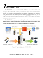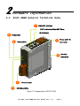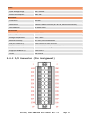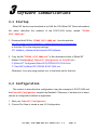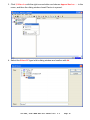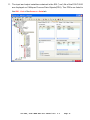
1
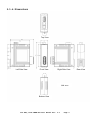
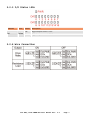
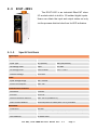
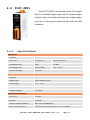
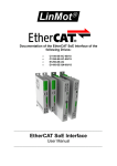
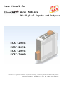
User Manual for Slave Modules ECAT‐2000 with Digital Inputs and Outputs ECAT‐2045 ECAT‐2051 ECAT‐2055 ECAT‐2060 EtherCAT® is a registered trademark and patented technology, licensed by Beckhoff Automation GmbH, Germany. Copyright © 2013 by ICP DAS Co., Ltd. All rights are reserved. LEGEL NOTICE Warranty All products manufactured by ICP DAS are under warranty regarding defective materials for a period of one year, beginning from the date of delivery to the original purchaser. Warning ICP DAS assumes no liability for any damage resulting from the use of this product. ICP DAS reserves the right to change this manual at any time without notice. The information furnished by ICP DAS is believed to be accurate and reliable. However, no responsibility is assumed by ICP DAS for its use, nor for any infringements of patents or other rights of third parties resulting from its use. Copyright Copyright © 2013 by ICP DAS. All rights are reserved. Trademarks Names are used for identification purpose only and may be registered trademarks of their respective companies. Technology Support If you have any question for our products, please contact us directly or email [email protected] Shipping Items The shipping package includes the following items: ECAT‐2000 Quick Start CD NOTICE If any of these items is missing or damaged, please contact your local distributor for more information. Keep the shipping materials and overall package in case you want to ship the module back in the future. More Information Manual: CD: \fieldbus_cd\ethercat\slave\ecat-2000\manual http://ftp.icpdas.com/pub/cd/fieldbus_cd/ethercat/slave/ecat-2000/manual/ ENI: CD: \fieldbus_cd\ethercat\slave\ecat-2000\software http://ftp.icpdas.com/pub/cd/fieldbus_cd/ethercat/slave/ecat-2000/software/ FAQ: http://www.icpdas.com/root/support/faq/faq.html Table of Contents 1 Introduction.................................................. 1 2 Hardware Information.......................................... 2 2.1 ECAT‐2000 General Technical Data ............................. 2 2.1.1 2.1.2 2.1.3 2.1.4 2.1.5 2.1.6 EtherCAT Interface ..............................................3 Power and F.G. Connector ........................................3 Power LED .......................................................3 Status LEDs .....................................................3 I/O Status LEDs .................................................3 Dimensions ......................................................4 2.2 ECAT‐2045 .................................................... 5 2.2.1 2.2.2 2.2.3 2.2.4 Specifications ..................................................5 I/O Connector (Pin Assignment) ..................................6 I/O Status LEDs .................................................7 Wire Connection .................................................7 2.3 ECAT‐2051 .................................................... 8 2.3.1 2.3.2 2.3.3 2.3.4 Specifications ..................................................8 I/O Connector (Pin Assignment) ..................................9 I/O Status LEDs ................................................10 Wire Connection ................................................10 2.4 ECAT‐2055 ................................................... 11 2.4.1 2.4.2 2.4.3 2.4.4 Specifications .................................................11 I/O Connector (Pin Assignment) .................................12 I/O Status LEDs ................................................13 Wire Connection ................................................13 2.5 ECAT‐2060 ................................................... 14 2.5.1 2.5.2 2.5.3 2.5.4 Specifications .................................................14 I/O Connector (Pin Assignment) .................................15 I/O Status LEDs ................................................16 Wire Connection ................................................16 3 Software Communications ................................. 17 3.1 Startup ...................................................... 17 3.2 Configuration ................................................ 17 A Glossary ................................................ 22 A.1 Ordering Information ......................................... 22 A.2 Technical Support ............................................ 22 1 Introduction The ECAT-2000 series are industrial EtherCAT slave remote I/O modules and equipped with the EtherCAT protocol and installed by daisy chain connection which permits the flexibility in devices installation and reduces infrastructure and operation costs. All the modules can be deployed in the network topologies such as star, line or ring. The isolated input and output design protects the ECAT-2000 against the harmful interference and environment. The ECAT-2000 has passed and verified by the conformance test tool, therefore eligible EtherCAT Master or configurator can manipulate it simply and implement your various applications easily. Fig 1.1 is shown a typical EtherCAT application. Figure 1.1 Typical Application of ECAT-2000 . ICP DAS, ECAT‐2000 DIO User Manual Rev. 1.1 Page 1 2 Hardware Information 2.1 ECAT‐2000 General Technical Data 1 EtherCAT Interface OUT: to Next the EtherCAT Slave IN: to Master 5 Power LED 4 Power and F.G. 2 Status LEDs Connector 3 7 6 DIN-Rail installation I/O Connector I/O Status LEDs Figure 2.1 Appearance of ECAT-2000 ICP DAS, ECAT‐2000 DIO User Manual Rev. 1.1 Page 2 2.1.1 EtherCAT Interface Notation Description IN EtherCAT data processing, direction to the EtherCAT master OUT EtherCAT data processing, direction to the next slave device 2.1.2 Power and F.G. Connector Notation Description +Vs Power Supply with +10~+30VDC GND Power Supply Ground F.G. Frame Ground; i.e. Earth Contact 2.1.3 Power LED Notation Color States Description PWR Red On The device is powered up 2.1.4 Status LEDs Notation RUN Color Red Link Activity Green IN/OUT States Description Off The device is in state INIT Blinking The device is in state PRE‐OPERARIONAL Single Flash The device is in state SAFE‐OPERARIONAL On The device is in state OPERARIONAL Off No link Blinking Link and activity On Link without activity 2.1.5 I/O Status LEDs Notation Color DI Yellow DO Yellow States Description Off Input voltage is below the lower switching threshold voltage On Input voltage is higher than the upper switching threshold voltage Off Digital output status is “Off” On Digital output status is “On” ICP DAS, ECAT‐2000 DIO User Manual Rev. 1.1 Page 3 2.1.6 Dimensions Top View Left Side View Front View Right Side View Unit: mm Bottom View ICP DAS, ECAT‐2000 DIO User Manual Rev. 1.1 Page 4 Rear View 2.2 ECAT‐2045 The ECAT-2045 is an industrial EtherCAT slave I/O module which is built in 16 isolated digital outputs. Users can obtain the input and output status not only via the process data but also from its LED indicators. 2.2.1 Specifications Digital Output Channels 16 Output Type Open Collector (Sink) Load Voltage +3.5 ~ +50 V Max. Load Current 700mA per Channel Isolation Voltage 3750 Vrms Power Input Voltage Range 10V ~ 30VDC Power Consumption Max. 4W Communication Interface Connector 2 x RJ‐45 Protocol EtherCAT Distance between Stations Max. 100 m (100BASE‐TX) Data Transfer Medium Ethernet/EtherCAT Cable (Min. CAT 5), Shielded Mechanism Installation DIN‐Rail Dimensions 110mm x 90mm x 33mm (H x W x D, without connectors) Case Material UL 94V‐0 Level ICP DAS, ECAT‐2000 DIO User Manual Rev. 1.1 Page 5 Environment Operating Temperature ‐25°C ~ 75°C Storage Temperature ‐30°C ~ 80°C Relative Humidity 10 ~ 90%, No Condensation ESD (IEC 61000‐4‐2) 4 KV Contact for Each Channel EFT (IEC 61000‐4‐4) Power: 1 KV Class A; Signal: 1 KV Class A Surge (IEC 61000‐4‐5) 1 KV Class A Hi‐Pot 1KV Class A 2.2.2 I/O Connector (Pin Assignment) ICP DAS, ECAT‐2000 DIO User Manual Rev. 1.1 Page 6 2.2.3 I/O Status LEDs Notation Color DO Yellow States Description Off Digital output status is “Off” On Digital output status is “On” 2.2.4 Wire Connection ICP DAS, ECAT‐2000 DIO User Manual Rev. 1.1 Page 7 2.3 ECAT‐2051 The ECAT-2051 is an industrial EtherCAT slave I/O module which is built in 16 isolated digital inputs. Users can obtain the input and output status not only via the process data but also from its LED indicators. 2.3.1 Specifications Digital Input Channels 16 Input Type Dry (Source) Wet (Sink/Source) Off Voltage Level Open +4V Max. On Voltage Level Close to GND +10 V ~ +50 V Isolation Voltage 3750 VDC Power Input Voltage Range 10V ~ 30VDC Power Consumption Max. 4W Communication Interface Connector 2 x RJ‐45 Protocol EtherCAT Distance between Stations Max. 100 m (100BASE‐TX) Data Transfer Medium Ethernet/EtherCAT Cable (Min. CAT 5), Shielded Mechanism Installation DIN‐Rail Dimensions 110mm x 90mm x 33mm (H x W x D, without connectors) Case Material UL 94V‐0 Level ICP DAS, ECAT‐2000 DIO User Manual Rev. 1.1 Page 8 Environment Operating Temperature ‐25°C ~ 75°C Storage Temperature ‐30°C ~ 80°C Relative Humidity 10 ~ 90%, No Condensation ESD (IEC 61000‐4‐2) 4 KV Contact for Each Channel EFT (IEC 61000‐4‐4) Power: 1 KV Class A; Signal: 1 KV Class A Surge (IEC 61000‐4‐5) 1 KV Class A Hi‐Pot 1KV Class A 2.3.2 I/O Connector (Pin Assignment) ICP DAS, ECAT‐2000 DIO User Manual Rev. 1.1 Page 9 2.3.3 I/O Status LEDs Notation Color DI Yellow States Description Off Input voltage is lower than +4VDC(Max.) On Input voltage is higher than “Off” state 2.3.4 Wire Connection ICP DAS, ECAT‐2000 DIO User Manual Rev. 1.1 Page 10 2.4 ECAT‐2055 The ECAT-2055 is an industrial slave I/O module built in 8 isolated digital inputs and 8 isolated digital outputs. Users can obtain the input and output status not only via the process data but also from its LED indicators. 2.4.1 Specifications Digital Input Channels 8 Input Type Dry (Source) Wet (Sink/Source) Off Voltage Level Open +4V Max. On Voltage Level Close to GND +10 V ~ +50 V Isolation Voltage 3750 VDC Digital Output Channels 8 Output Type Open Collector (Sink) Load Voltage +3.5 ~ +50 V Max. Load Current 700mA per Channel Isolation Voltage 3750 Vrms Communication Interface Connector 2 x RJ‐45 Protocol EtherCAT Distance between Stations Max. 100 m (100BASE‐TX) Data Transfer Medium Ethernet/EtherCAT Cable (Min. CAT 5), Shielded ICP DAS, ECAT‐2000 DIO User Manual Rev. 1.1 Page 11 Power Input Voltage Range 10V ~ 30VDC Power Consumption Max. 4W Mechanism Installation DIN‐Rail Dimensions 110mm x 90mm x 33mm (H x W x D, without connectors) Case Material UL 94V‐0 Level Environment Operating Temperature ‐25°C ~ 75°C Storage Temperature ‐30°C ~ 80°C Relative Humidity 10 ~ 90%, No Condensation ESD (IEC 61000‐4‐2) 4 KV Contact for Each Channel EFT (IEC 61000‐4‐4) Power: 1 KV Class A; Signal: 1 KV Class A Surge (IEC 61000‐4‐5) 1 KV Class A Hi‐Pot 1KV Class A 2.4.2 I/O Connector (Pin Assignment) ICP DAS, ECAT‐2000 DIO User Manual Rev. 1.1 Page 12 2.4.3 I/O Status LEDs Notation Color DI Yellow DO Yellow States Description Off Input voltage is lower than +4VDC(Max.) On Input voltage is higher than “Off” state Off Digital output status is “Off” On Digital output status is “On” 2.4.4 Wire Connection ICP DAS, ECAT‐2000 DIO User Manual Rev. 1.1 Page 13 2.5 ECAT‐2060 The ECAT-2060 is an industrial slave I/O module built in 6 isolated digital inputs and 6 isolated relay outputs. Users can obtain the input and output status not only via the process data but also from its LED indicators. 2.5.1 Specifications Digital Input Channels 6 Input Type Dry (Source) Wet (Sink/Source) Off Voltage Level Open +4V Max. On Voltage Level Close to GND +10 V ~ +50 V Isolation Voltage 3750 VDC Digital Output Channels 6 Output Type Form A (SPST‐NO) Contact Rating (Resistive Load) 5A@30VDC; 5A@125/250VAC(47~63Hz) Operate Time 10 ms Max. Release Time 5 ms Max. Mechanical Endurance 2 x 10⁷ Ops. Electrical Endurance 105 Ops. Power Input Voltage Range 10V ~ 30VDC Power Consumption Max. 4W ICP DAS, ECAT‐2000 DIO User Manual Rev. 1.1 Page 14 Communication Interface Connector 2 x RJ‐45 Protocol EtherCAT Distance between Stations Max. 100 m (100BASE‐TX) Data Transfer Medium Ethernet/EtherCAT Cable (Min. CAT 5), Shielded Mechanism Installation DIN‐Rail Dimensions 110mm x 90mm x 33mm (H x W x D, without connectors) Case Material UL 94V‐0 Level Environment Operating Temperature ‐25°C ~ 75°C Storage Temperature ‐30°C ~ 80°C Relative Humidity 10 ~ 90%, No Condensation ESD (IEC 61000‐4‐2) 4 KV Contact for Each Channel EFT (IEC 61000‐4‐4) Power: 1 KV Class A; Signal: 1 KV Class A Surge (IEC 61000‐4‐5) 1 KV Class A Hi‐Pot 1KV Class A 2.5.2 I/O Connector (Pin Assignment) ICP DAS, ECAT‐2000 DIO User Manual Rev. 1.1 Page 15 2.5.3 I/O Status LEDs Notation Color DI Yellow DO 2.5.4 Yellow States Description Off Input voltage is lower than +4VDC(Max.) On Input voltage is higher than “Off” state Off Digital output status is “Off” On Digital output status is “On” Wire Connection ICP DAS, ECAT‐2000 DIO User Manual Rev. 1.1 Page 16 3 Software Communications 3.1 Startup EtherCAT devices are described in an XML file, ESI (EtherCAT Slave Information) file, which describes the modules of the ECAT-2000 series named "ICPDAS ECAT‐2000.xml." 1. Download the ESI file, ICPDAS ECAT‐2000.xml, from the website http://ftp.icpdas.com/pub/cd/fieldbus_cd/ethercat/slave/ecat-2000/software/ or from the CD in the shipping package CD: \fieldbus_cd\ethercat\slave\ecat-2000\software 2. Copy the file "ICPDAS ECAT‐2000.xml" to the destination folder of EtherCAT Master Tools(Beckhoff EtherCAT Configurator or TwinCAT etc.) C:\EtherCAT Configurator\EtherCAT\ICPDAS ECAT-2000.xml C:\TwinCAT\Io\EtherCAT\ICPDAS ECAT-2000.xml Otherwise, if you are using another tool, to the folder set for that tool. 3.2 Configuration This section is described the configuration using the example of ECAT-2055 and the EtherCAT Configurator supplied by Beckhoff. Otherwise, if another tool is used, choose a configuration method as applicable. 1. Start your EtherCAT Configurator. 2. Choose File, New to create a new I/O Configuration. ICP DAS, ECAT‐2000 DIO User Manual Rev. 1.1 Page 17 3. Click I/O Device with the right mouse button and choose Append Device... in the menu, and then the dialog window Insert Device is opened. 4. Select the EtherCAT type in this dialog window and confirm with OK. ICP DAS, ECAT‐2000 DIO User Manual Rev. 1.1 Page 18 5. Device 1 (EtherCAT) is added to to your configuration, i.e. a new EtherCAT line. Click Device 1(EtherCAT) with the right mouse button and choose Scan Boxes... in the menu. 6. Choose the correct network device which is connected to ECAT-2000. ICP DAS, ECAT‐2000 DIO User Manual Rev. 1.1 Page 19 7. If the hint is shown, click Yes/OK and continue. 8. Click Yes to start scanning for ECAT-2000. 9. Click Yes to activate the free run mode for EtherCAT Configurator. 10. The ECAT‐2000 (Box 1) is now shown in the EtherCAT Configurator. ICP DAS, ECAT‐2000 DIO User Manual Rev. 1.1 Page 20 11. The input and output variables contained in the ESI (*.xml) file of the ECAT-2000 are displayed as CANopen Process Data Objects(PDO). The PDOs are listed in the PDO List of the Process Data tab. ICP DAS, ECAT‐2000 DIO User Manual Rev. 1.1 Page 21 A Glossary A.1 Ordering Information EtherCAT Slave DIO Modules ECAT‐2045CR EtherCAT Slave I/O Module with Isolated 16‐ch DO (RoHS) ECAT‐2051 CR EtherCAT Slave I/O Module with Isolated 16‐ch DI (RoHS) ECAT‐2055 CR EtherCAT Slave I/O Module with Isolated 8‐ch DO and 8‐ch DI (RoHS) A.2 Technical Support If you have any difficulties using your ECAT-2000 series modules, please contact us or send a description for the problem to [email protected]. ICP DAS, ECAT‐2000 DIO User Manual Rev. 1.1 Page 22