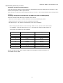
1
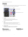
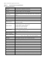
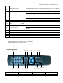
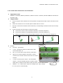
USER’S MANUAL
Version : 051223
Model 30450712
MPEG-4 Hi-Resolution Real-time Triplex DVR
8 Channels
30450712 MPEG-4 Hi-Resolution DVR
Table Of Contents
Important Notice ........................................................................................................ 2
Operation precautions .................................................................................................. 3
Chapter 1 Product Features and Specifications.................................................................. 4
1.1
Technical Specifications................................................................................. 4
1.2
Product Features.......................................................................................... 5
Chapter 2 Installation................................................................................................... 7
2.1 Hard Disk Installation ...................................................................................... 7
2.2 Front Panel Introduction................................................................................... 8
2.3 Remote Controller........................................................................................... 9
2.4 Back Panel Introduction ................................................................................... 10
Chapter 3 System Operation ......................................................................................... 12
3.1 Turn on/off the recorder ................................................................................. 12
3.2 Recording operation....................................................................................... 12
3.3 Alarm connection operation............................................................................. 13
3.4 Pan-Tilt-Zoom control operation....................................................................... 13
3.5 Network connection operation ......................................................................... 13
Chapter 4 Front Panel And Remote Controller Operation..................................................... 14
4.1 Operation Menu Introduction........................................................................... 14
4.2 Menu Operation ............................................................................................ 19
4.3 Main Menu Operation..................................................................................... 22
Chapter 5 Operation Over Network................................................................................. 30
5.1 Setting on the client end ................................................................................ 30
5.2 Login and Logout .......................................................................................... 30
5.3 Operation of the right key menu ...................................................................... 31
5.4 Operation of the Records Search...................................................................... 33
5.5 Operation of the Config ................................................................................. 35
5.6 Operation of the Assistant .............................................................................. 39
Chapter 6 Serial port Operation ..................................................................................... 42
6.1 System setting of the Mini Terminal .................................................................. 42
6.2 Serial port upgrading operation ....................................................................... 42
Chapter 7 Frequent Questions and Answers ..................................................................... 43
Appendix ................................................................................................................... 45
A. Operation of DVR with Speed Dome............................................................................ 45
1
MPEG-4 Hi-Resolution Digital Video Recorder
Important Notice
1.
Power supply
This DVR uses a 110V/230V AC switching type power supply input, please check carefully the voltage switch
is properly set to fit your power source before you power ON this DVR.
Power ON/OFF switch
Can be switched from 230V / 115V
2.
Hard Disk
This DVR will only start after HDD is properly installed.
Please install at least one HDD (Maxtor is the only recommended).
HDD capacity can be 80GB up to 300GB.
3.
CD-RW
A SONY CD-RW model 230A (IDE type) is recommended for the D1 DVR, or
A BenQ model 5232WI (USB type) is recommended for the D1 DVR.
For DVR CIF resolution models, a SONY DVD-RW model 710A is also supported.
4.
Operating this DVR
Press ENTER key or click USB mouse once, for entering password.
The default password is 888888, for initially entering this DVR.
DVR :
D1 resolution DVR
# 3045076 – 4CH (2CIF – 640 x 240)
# 30450711 – 4CH
# 3045077 – 8CH (2CIF – 640 x 240)
# 30450712 – 8CH
# 3045078 – 16CH (CIF – 320 x 240)
2
30450712 MPEG-4 Hi-Resolution DVR
Operation precautions
All the safety and operating instructions should be read before the appliance is operated The improper
operation may cause irreparable damage to the appliance.
1
2
Installation condition
1.1
Put away from extreme hot places and humid places
1.2
Avoid direct sunlight
1.3
Be horizontally installed
1.4
Avoid violent vibrating, lefts and place gently
1.5
Do not place other devices upon
1.6
Put in well ventilation places, not block the radiator fan in the back of the recorder
Installation and operation precautions
2.1
Please check the main power switch and voltage of power supply to avoid voltage mismatch attach the
power cable to the unit and connect it to your local mains supply, then open the power
2.2
At the first use, assure the installation of hard disk and the master-slave jumper wire should be set.
MAXTOR hard disk is strongly recommend
2.3
Do not unplug the power connector before turn the power off correctly and switch the power on & off
within short period
3
2.4
Unauthorized repair or pats substitutions may result in fire, electric shock or other hazards
2.5
do not attempt to service this equipment by yourself refer all servicing to qualified service personnel
Open cabinet and check inventory
Check the items supplied against the list below after open the case
3.1
One power Cord x 1
3.2
Ethernet cable (positive cable) x 1
3.3
One serial port cable x 1
3.4
User manual x 1
3.5
CD-ROM for installation x 1
3.6
One 25-pin alarm converter x 1
3
MPEG-4 Hi-Resolution Digital Video Recorder
Chapter 1
Product Features and Specifications
1.1 Technical Specifications
Parameter
30450712 – 8 Channel
Processor
High performance embedded microprocessor
Operation system
Embedded Linux Operation System
Interface
GUI, Mouse support, menu color changeable
Video input
8 composite video input (NTSC/PAL) BNC, (10Vp-p. 75O)
Video output
1 PAL/NTSC composite video output, BNC(10Vp-p. 75O), 1 VGA monitor
output
Audio input
8 Channel 1200~2800mv30KO (BNC)
Audio Output
1 Channel 3500mv 3KO (BNC)
Screen division
1, 4, 9 display
Video format
NTSC (525 line, 60f/s), PAL (625 line, 50f/s)
System resource
Real-time recording, one channel playback and network operation
simultaneous (Triplex)
NTSC/PAL Real-time monitor D1 720x480/704x576
NTSC/PAL Playback D1 704 x 480/704x576
Image resolution
NTSC/PAL Half-D1 360x480/352x576
NTSC/PAL DCIF 720x240 /704x288
NTSC/PAL CIF 360x240 / 352x288
Motion detection
Area setting 192 (16x12) areas setup for each channel; detection sense
setting : Multiple levels detection sense
Video compression
MPEG-4 , H.264
Audio compression
PCM
Video recording speed
Real-time mode : NTSC – 1fps ~30fps for each channel adjustable
PAL
– 1fps ~ 25fps for each channel adjustable
Image quality
6 levels selectable
Hard disk
Inside equipped 4 IDE ports, able to install 8 HDDs inside
HDD space used
Audio : PCM 28.8Mbyte/Hour Video : 40 ~ 2000Mbyte/hour
Alarm input
4 channel voltage alarm input (+5V ~ +15VDC. Needed for the alarm input)
Alarm output
3 channel output ( 2 NO contact, 1 controllable + 12V output)
Alarm relay
30VDC 1A, 125VAC 0.5A-relay output
Network connection
RJ45 10M/100M Ethernet connection
Pan-Tilt control
RS-485, RS-232
Power supply
115V / 230V 47/63Hz
Power consume
40W (without HDD)
Working temperature
-10℃ ~ + 55℃
Working humidity
10% ~ 90%
Barometric pressure
86kpa ~ 106kpa
Dimension
2U standard industrial case, 441mm(W) x 430mm(L) x 89mm(H)
Weight
Approx 11KG without HDD weight
4
30450712 MPEG-4 Hi-Resolution DVR
Installation
Shelf installation , flat installation
1.2 Product Features
Real-time Monitor
l
Video output port and VGA port, able to realize monitoring on the monitor or PC type monitor
l
Single window / Four windows
l
Multi window / Single window patrol sequentially on pre-determined intervals
l
Real-time display bit stream and HDD space occupied per hour
l
Display channel status such as recording motion detection, video loss, monitoring covered
Compression Method
l
Multiple video compression mode : MPEG-4, H.264
l
4 Channel audio/video real-time compression, independent hardware compression for each channel,
stable synchronization of sound and image
Storage
l
4 IDE port support up to 8 large capacity built-in HDDs
l
Alternate HDD working method, Hard disks con be put into idle mode if not accessed for a period of
time Greatly reduces the power consuming and heat emission, hard disks can be used for much
longer time
l
Choose overwrite or stop modes when hard drive is full
l
Use special format to save recording keep the data from being juggled and ensure the secure
storage
Back-up
l
Support CD-RW drive to back up records onto CD through USB port
l
USB port support multi-backup device include removable HDD, flash disk
l
Download the file from DVR to local PC through network
l
Preserve the file on HDD by setting the HDD read-only
Play and record
l
Support multiplex operation : Real-time display/record in all channels, one channel play-back,
remote operations search for downloading, simultaneously while recordings are in progress
l
Multiple recording mode : manual, schedule, alarm, motion detection, alarm recording and motion
detection recording are with pre-recording function
l
Playback : PIP or multi-channel function realize real-time monitoring during playback, playback
also available using
Network connection
l
Fast search and playback for schedule recording and alarm recording
l
Playback at adjustable speeds : X2 , forward, 15fps, 5fps slow play or view frame by frame, pause
and revise
l
Display the original event time/date during playback
5
MPEG-4 Hi-Resolution Digital Video Recorder
Alarm relay
l
8 channel external alarm input, video lost alarm and motion detection alarm
l
Multi channel alarm output switch realize quick alarm relay and on-spot light control
l
Protection circuit for alarm input and output assure the intactness of the main device
Pan-Tilt-Zoom Control
l
Support Pan-Tilt-Zoom (PTZ) Functions using RS485 communication protocol
l
Able to integrate multiple decoding protocol so as to control various pan-tilt and speed dome
Communication connection port
l
RS-485 (25pin port) connection realize alarm input and PTZ control
l
RS-232 port support multiplex function – connecting a modem for the dial-up to the net , with
keyboard for central control connect to the computer serial port for system upgrading and
debugging or link to different matrix
l
Standard Ethernet port for remote viewing and control
Network function
l
Remote real-time monitor and operate
l
Pan-Tilt-Zoom control
l
Recording search and real-time playback ( The image quality depends on the network condition),
downloading records through network
l
System setting modification and system software upgrading online
l
Remote alarm processing and system log reviewing
l
Talkback between administrator and the DVR
l
Embedded TCP/IP protocol and RTOS ( Real-Time Operating System) supports web server direct
visit to realize all the function above
l
Administration mode : support 3 levels user password protection, to prevent any unauthorized use
of product
6
30450712 MPEG-4 Hi-Resolution DVR
Chapter 2
Installation
2.1 Hard disk installation
please install HDD first refer to the below installation instructions. Up to eight 10G-infinite capacity hard
disk can be installed internally. The installed HDD number can be decided according to the required image
quality, recording time and HDD capacity.
2.1.1 Steps of HDD Installation
Master
Slave
1. Dismantle the top
2. Dismantle the HDD
cover, open the cabinet
bracket
3. Install HD
4. Set the master-slave
jumper on the same IDE
port ( refer to the clue on
the back of the HDD)
5. Fix the HD bracket
6. Connect the IDE cable
7. Close the cover and
and plug in the power
install the screws
cable
Structure of CD-RW bracket with 4HDD, and 8HDD without CD-RW
2
3
4
1
Fixture with CD-RW and
Fixture without CD-RW
less than 4 HDDs
but maximum 8 HDDs
4 IDE ports
Note : It is not necessary to dismantle the HD bracket if less than 4 HDDs are installed
2.1.2 Steps of CD-RW installation
1. Dismantle the CD-RW
2. Remove the baffle of
3. Fix the CD-RW on the
4. Reinstall the CD-RW
bracket inside the casing
CD driver from inside.
CD-RW bracket
bracket in the casing.
7
MPEG-4 Hi-Resolution Digital Video Recorder
2.2 Front panel introduction
1.
Power
2.
Remote receiver
3.
Record indicator light
4.
CD-RW
5.
USB port
6.
Play / Pause
7.
Slow play
8.
Rewind
9.
Play last section
10. Play next section
13. Number key
14. Single window
display
11. Forward
12. Function indicator light
15. Up direction key
16. Exit
17. Left direction key
18. Function
19. Down direction key
20. Record
21. Right direction key
22. Enter
23. Outer Jog Shuttle
24. Exit
25. Multi-window display
26. Enter
27. Standby
28. Power indication light
Key Functions
No.
Name
Sign
1
Power switch
2
Remote receiver
To receive the remote signal
3
Record indicator light
The light turn on red means the certain channel is on recording
4
CD-RW
Backup records
5
USB port
To connect with the USB device
6
Play / Pause
7
Slow Play
9
Play last section
10
Play next section
11
Forward
12
13
15,19
16,24
Function indicator
light
POWER
Function
„/;
Power on/off (press for 3 sec. to turn off the DVR)
Play/ Pause
3 levels of slow play speed adjustable ( 15fps ~ 5fps)
I|
Play the last recording file before the current file
Play the next recording file after the current file
8
Forward at 5 adjustable speed x 1 (normal)
The light on during function assistant key in using
Number key
Manual password number input, window shift or number input
Up/Down direction
Up and down on screen cursor control; change setup; change number,
key
PTZ control
Exit
Come back to previous menu
8
30450712 MPEG-4 Hi-Resolution DVR
Escape or cancel
17, 21
Left/Right direction
Left and Right on screen cursor control; shifting level 1 and level2
key
menus; Pan control
Click to display the PTZ and the image menu under full screen mode.
Shift the PTZ function menu in Pan-Tilt
18
Function
Fn
To enable cursor field selection with the arrow keys when set MD area
To display the playback state bar during playback
Choose/ channel the backup file when backup
20
Record
22
Enter
Start / stop recording , work with arrow keys or number keys
Enter cursor selection
ENTER
Enter main menu
Equal to Left/Right direction key
23
Outer Jog Shuttle
Clockwise realize forward and counter clockwise realize revise when
playback
25
Multi-window display
The shift the screen between full and multi-window display
26
Enter
Confirm the menu operation
27
Standby
The light on during the DVR is in standby mode
28
Power indication light
Indication light
l
Connect the mouse to the USB port at the back panel
l
Function (take the right hander for example)
Click the left key and the menu pop up for choosing
Click the right key to enter the menu
Double-click the left key to save the settings and exit the menu
Click the right key to cancel the setting and exit the menu
2.3 Remote controller
(1)
(2)
(5)
(3)
(4)
(7)
(8)
(9) (11) (16)
(10)
(6)
(14)
(13)
(12)
(15)
1. Remote address
2. Multi-window shifting
3. Number
4. Record
5. Function assistant
6. Enter/Menu
7. Cancel
8. Direction
9
MPEG-4 Hi-Resolution Digital Video Recorder
9. Jump forward
10. Play last section
11. Jump backwards
12. Pause
13. Play next section
14. Slow play
15. Play/ Pause
16. Fast play
2.4 Back panel introduction
Number
Function
Number
Function
1
Alarm – RS485 connection
2
Audio output
3
Audio input
4
Power switch
5
Power plug
6
RS232 connection
7
VGA connection
8
USB connection
9
NET network connection (RJ45)
11
10
Video output
Video input
Network connection note : When connecting directly to the network card of the computer, please use CAT-5
crossover cable, when connecting to a LAN or Router use CAT-5e cable.
10
30450712 MPEG-4 Hi-Resolution DVR
2.4.1 25 Pin alarm transfer box user illustration
l
Application areas
Suitable for 3045076,3045077,30450711,30450712 series 4 channel, 8channel MPEG-4 DVR with 25
pin alarm input .
l
Usage method
A.
Connect 25 pins of the transfer box directly with the 25 pins alarm input output connection of the
DVR
B.
Fasten the transfer box on the back panel of DVR with two screws
C.
Pull out 6 connection terminals of the transfer box, corresponding connection marks can be clearly
noticed
D.
Connect function line according to connection marks
u
Loosen the screws on the connection terminal ( connection diagram 1)
u
Insert lines needed to corresponding terminals ( connection diagram 2)
u
Fasten the screws on the terminals after insertion of the lines (connection diagram 3)
1. Connection diagram
l
2. Connection diagram
3. Connection diagram
terminal
Remark
E.
“Ground” : ground line;
F.
“+12V” : Provide the power to alarm device with
current less than 2 A
G.
“Out 1,2” is two alarm output switch normal open
H.
“485 A, B” is communication connection, used to
connect such recorder control device such as control
decoder
I.
“+12© ” is control power output – the third alarm
output , is used for standby power for smoke sensor
alarm device. Dismiss of the alarm needs the device to turn off the power
J.
“ALARM 1… .8” is alarm input. High level voltage input. Input voltage
is 5-12V (12V is recommended)
11
screw
MPEG-4 Hi-Resolution Digital Video Recorder
Chapter 3
System operation
*Please confirm the HDD to be installed and the proper connection before turning on the DVR*
*For the correction method, refer to Chapter 2 – Installation*
3.1 Turn on/off the recorder
3.1.1 Turn on the recorder
Plug in the power cable, switch on the power button at the back of the recorder, power indicator light
on; DVR on; default 9 windows for the video output display. If the starting time is within the
programmed recording time, the system will start recording function automatically. Corresponding
channel indicator light on and system work in a normal manner.
Note: if the system stops during HDD boot detection, the HDD many not be installed right and please
check the HDD connections (Ribbon and power connections).
3.1.2 Enter the setting menu
Press Enter the login screen appears on monitor before you enter the menu, you must input the
password. There are two level of password – user password and administrator password
User password
666666
Administrator password
888888
With user password, you are also not allowed to enter system setting and admin setting.
Note: For the consideration of security, please change the setting in admin setting refer Chapter4
3.1.3 Turn off the recorder
*please unplug the 220VAC power supply during HDD installation*
Press the POWER key on the front panel for 3 seconds to stop the current operations. Then switch off
the power button at the back panel of the DVR to turn off the power.
3.1.4 Power off recovery
When the power is cut off abnormally, the recorder will recall its last state and continue where it left off
The state indicator light is the same as it was before the power off
3.1.5 Change the battery of the DVR
Change the battery of the DVR, recommend to the same type of Lithium fastener batteries
Note: Please check the system time in time and generally change the battery each year toe ensure the
veracity time.
3.2 Recording operation
The default recording mode after the starting of DVR is 24 hours continuous recording user can choose the
suitable recording mode due to the necessity. Instructions for the difference or ding modes as follows:
l
Schedule recording
n
Enter the menu, and set the timing period for the recording see details at Menu -> system setting
-> schedule
12
30450712 MPEG-4 Hi-Resolution DVR
l
Manual recording
n
Press “ REC” button on the remote controller or “?” on the front panel (need input the
administrator password)
n
Check the status of each channel in the recording menu; “■” channel are in recording. while “?”
means the channel1 is not in recording
n
Select the channel to be recorded, please press the related number key (or use “p q ” key/jog
shuttle choosing) make the channel “■” on the screen then press Enter to start recording
l
n
Repeat above steps and make the channel “?” to stop the camera from recording
n
Press ESC to return.
Alarm recording
n
Connect the alarm input according to the device connection and the instructions
n
Set the related item in the menu to start alarm recording See details at Menu -> Setting-> Alarm
setting
l
Motion detection recording
n
Record the channel only in need of motion detection first confirm whether this channel is on
schedule recording if it is, please close the schedule recording
n
Set the related items in the menu to start motion detection recording see details at Menu ->
System setting -> Motion detection.
3.3 Alarm connection operation
l
Connect the alarm input according to the device connection and the instructions
l
Connect the related alarm output according to the necessity ( Example : light, beeper, etc..)
l
Set the related item in the menu. See details at Menu -> System setting -> Alarm setting
3.4 Pan-Tilt-Zoom control operation
l
Confirm the right connect of PTZ and the decoder and set the proper decoder address
l
Confirm the right connection of decoder’s A,B line and the 15-pin port’s A,B line of DVR
l
Set the related items in the menu. See details at Menu -> System setting -> Pan-Tilt control
l
Shift the monitor image to the single window monitor of the channel in need of Pan-Tilt control
l
continuously press “ Assistant” on the remote controller or “Fn” on the front panel to shift the items on
the screen
l
Use direction key to move and control the selections on the screen
3.5 Network connection operation
l
Confirm the correct network connection between DVR and computer
l
Set the IP address, subnet mask and gateway of the computer and DVR separately ( if there is no router
among the network, only the IP address, if there is routers in the network, please set the related
gateway and subnet mask)
l
Use ping ***.***.***.*** (IP address of DVR) to check the link of the network, replied TTL values less
the 64 is normal
l
Open IE Browser and input the IP address of the DVR you want to log in
l
Network operation see details at Chapter 5 operation through network.
13
MPEG-4 Hi-Resolution Digital Video Recorder
Chapter 4
Front panel and remote controller operation
4.1 Operation menu introduction
*The green item is the current selectable one*
4.1.1 Menu shifting and setting
Operation
Button-pressing
step
order
Instruction
Screen display
During real-time monitor, press Enter
(or click the left key of the mouse ) to
Enter main
1. Confirm Enter
correct password (default six 6 or six 8)
menu and
level 1
submenu
to enter the menu
2. Direction (jog
Use arrows (or mouse pointer) to
shuttle) pqut
select the main menu select
3. Confirm Enter
Enter level 2
submenu
open the login interface, key in the
Enter the selected level 1 submenu (or
click the left key of the mouse)
4. Direction (joy
Use arrows (or mouse pointer) again to
shuttle) pqut
select level 2 submenu selection
5. Confirm Enter
Press to enter selected level 2
submenu (or click the left key of the
mouse)
1. Direction (jog
Select the revised option, the green
shuttle) u
item is the current selection, use pq
(or click the left key of the mouse) to
revise and u ( or mouse pointer) to
Set
menu
contents
select the next menu selection
2. Direction pq
Use up/down arrows (or click the left
key of the mouse to chose ) to revise
the settings
3. Confirm Enter
Press Enter ( or click the left key of the
of the mouse ) to save the revised item
Exit the
Direction (Joy
Return to the last option of the current
current
shuttle) t
menu
Cancel ESC
Exit to the previous menu (or click the
menu
right key of the mouse)
l
You can set multiple channels and save all the setting together before exiting the current menu
14
30450712 MPEG-4 Hi-Resolution DVR
4.1.2 Menu Overview
Main menu
Menu level 1
SEARCH
FAST SEARCH
Menu level 2
CHANNEL
LIST SEARCH
For accurate search and playback
1
TIME
Remarks
24-07-2005
according to the channel and
02:20:00
time
TYPE ALL CHANNEL 1
Search records according to the
Realize fast
TIME
type ( All, General, Alarm, MD),
search list search
0 TYPE START TIME END TIME
channel and time List the results
and playback
SIZE(KB)
for choosing the wanted file and
24-07-2005 02:20 00 SEARCH
function
INFORMATION
playback
HDD INFO
IDE
1 2 3 4
Displayed the IDE parts’ state,
MASTER 0 ----------
the total and free space for all
SLAVE
and per HDD, the record starting
------------
Display the HDD
1 TYPE TOTALSPACE FREESPACE
and ending time
information,
STATUS
With “*” follow the HDD number
BPS, Alarm
ALL --
state, System
1 Read/Write 78162M 64208M Normal
78162M 64208M
log version and
etc..
means the current working HDD
Press Fn to check the recording
time of the HDD
BPS
CHANNEL Kb/s MB/H WAVE
Display the current BPS and the
1
1195
525
estimate for HDD space occupy
2
1185
521
per hour, and the wave graphics
display the BPS visualized
LOG
493 LOGTIME
494
EVENT
05-07-24 09:26:25
495 05-07-24 09:27:40
Display the important system
events’ log
lt page up ul Page down clear
Version
CHANNELS
4
ALARM IN
4
Display the information about
ALARM OUT 3
SYSTEM
XDVR 6.0
BUILD DATE 2004-11-2
WEB SERVER
15
operation system version, issue
date and so on
MPEG-4 Hi-Resolution Digital Video Recorder
SYSTEM
GENERAL
SETTING
SYS TIME
2004-11-2 11:11:00
LANGUAGE
ENGLISH
DATEFORMAT YYMMDD
Set system time, recording
Set the system
TIME FORMAT 24
parameter,
HDDFULL
OVERWRITE
image settings,
REC-LEN
60min
alarm settings
DVR NO.
008
serial
VIDEO
port(RS232) and
SHUTPSW
PTZ settings
DEFAULT
Main menu
SYSTEM
Encode
SETTING
will prompt need reboot to effect
DISABLE
SAVE
CANCEL
CHANNEL
1
COMPRESSION
MPEG-4
RESOLUTION
D1
BITRATE
VBR
QUALITY
4
FRAMERATE
parameter,
VIDEOLOSS
image settings,
ALARMOUT
alarm settings
DEFAULT
SCHEDULE
If change the language, system
Menu level 2
Set the system
serial
video format and so on
PAL
Menu level 1
TYPE
port(RS232) and
WEEK
PTZ settings
SUN
25
CLOSE
SAVE
SCHEDULE
CANCEL
CHANNEL 1
TIME1
TIME2
00:00~20:00¦ 00:00~24:00?
00:00~20:00¦ 00:00~24:00?
WEN 00:00~20:00¦ 00:00~24:00?
THR 00:00~20:00¦ 00:00~24:00?
FRI 00:00~20:00¦ 00:00~24:00?
SAT
Remarks
Coding format and so on
MON 00:00~20:00¦ 00:00~24:00?
TUE
parameter, the machine No.,
Set schedule for schedule, Motion
Detection, Alarm recording.
Be able to set 2 different period
everyday in a week separately
00:00~20:00 ¦ 00:00~24:00?
ALL 00:00~20:00? 00:00~24:00?
DEFAULT
RS232
SAVE
COM FUNC
BAUDRATE
HYPERTERM
115200
DATABIT
8
Set the RS232 function and the
STOPBIT
1
BaudRate parameter
VERIFY
NONE
DEFAULT
NETWORK
CANCEL
SAVE
CANCEL
IP ADDRESS
192.168.000.111
SUBNETMASK
255.255.255.000
GATEWAY
192.168.000.001
HTTP
80
TCP
37777
16
Set network parameter
30450712 MPEG-4 Hi-Resolution DVR
ALARM
PROTOCOL
TCP
DEFAULT
SAVE
ALARMIN
1
TYPE
NO
NO.
1
2
CANCEL
3
4 5 6 7 8
REC CHANNEL ■ □ □ □ □□□□
ALARM OUT
■ □ □
DELAY
30
Set alarm output and the relay
parameter
PRE-RECORD ■
TIP
Main menu
SYSTEM
□
Menu level 1
PAN-TILT
SETTING
Menu level 2
CHANNEL
1
PROTOCOL
NONE
ADDRESS
8
BAUDRATE
4800
DATARATE
8 bit
Set the system
STOPBIT
1 bit
parameter,
VERIFY
NONE
image settings,
DEFAULT
alarm settings
MONITOR
Remarks
See sensitivity, region, alarm
output and recording channel,
etc.
SAVE CANCEL
MENU OUTPUT
serial
MENU COLOR
port(RS232) and
BLACKTRANSPARENCY224
PTZ settings
MENU TOUR
Set parameters of menu output
INTERVAL 5 SEC
No.
SPLIT 1
SPLIT 4
SPLIT 9
DEFAULT
MOTION
CHANNEL
DETECTION
NO.
1
2
3
4
and monitor tour
□ □ □ □
□ □
□ □
SAVE CANCEL
1
1 2 3 4 5 6 7 8
REC CHANNEL ■ ?
ALMOUT
DELAY
? ? ? ? ? ?
■? ?
30
PRE-RECORD ■
output and recording channel,
etc.
TIP
?
SENS
MIDDLE
REGION
SET
DEFAULT
See sensitivity, region, alarm
SAVE CANCEL
17
MPEG-4 Hi-Resolution Digital Video Recorder
DEFAULT
Sure to restore all default setting
OK
ADVANCED
CANCEL
HDD
IDE
1
2
3
MANAGE
MASTER
0
-
-
-
SALVE
-
-
-
-
Restore all default setting
4
HDD No. 1 SET TO Read/Write EXECUTE
Set HDD attributes, clear data in
TYPE
READ/WRITE
HDD. The attributes can only be
STALUS
NORMAL
changed after restarting the
CAPABILITY 238464mb
system
RECORD TIME
Main menu
ADVANCED
Menu level 1
PASSWORD
Menu level 2
Remarks
USER
NEW
* * * * * *
CONFIRM * * * * * *
SAVE
CANCEL
ADMIN
Use advanced password to log in
OLD
* * * * * *
NEW
* * * * * *
change password
CONFIRM * * * * * *
MANAGE
SAVE
ALARM
******
CANCEL
1
2
□ □
OUTPUT
SAVE
ALARM
INPUT
1
2
RECORD
Manually produce output signal
3
4
5
6 7
8
□ □ □ □ □ □ □ □
Enable alarm input
1
2 3
CANCEL
4 5
6 7
8
□ □ □ □ □ □ □ □
Manually start or end recording
SAVE
NET USER
□
CANCEL
SAVE
MANUAL
3
CANCEL
Sure to restore net user ?
SAVE
CANCEL
18
Restore net user
30450712 MPEG-4 Hi-Resolution DVR
4.2 Menu Operation
4.2.1
Recording operation
Button-pressing order
Instruction
1. Record ¢
Press to enter screen display
2. Direction pq or the
Press to shift the recording state on/off.
related number key
The highlighted means on
3. Direction t u
Press to shift recording channels
4. OK
Press OK to save the setting
4.2.2
Display
Playback operation
Button-pressing order
Instruction
Press the button to enter screen display. After
1. Play/Pause
setting time, press play/Pause or Enter begin
the playback directly ( if the current state is
logout, please enter password)
2. Playback status bar
The bar displays channel No. , date, time,
playback speed, playback progress. Can
control playback speed, sound volume, etc.
You can hide the bar by pressing £ on the
front panel or hide icon on the top right corner
of the playback status bar
19
Display
MPEG-4 Hi-Resolution Digital Video Recorder
Shift to other channel
During playback, press number key (1 to 4),
during playback
then the system will start to play records on
related channel at the same time
Record information
During playback, press Fn to display or hide
display
the playback state bar
4.2.3
Playback fast play and slow play
Button-pressing order
Instruction
Remark
During playback press this key to shift
1. Fast play : press the
between multiple fast play speeds.
Fast play speed is relevant to the
key 8
Fast play key can be the reverse key of slow
version
play
2. Slow play : press the
During playback press this key to shift
key ?
between multiple slow play speeds.
Slow play key can be the reverse key of Fast
3. Play / Pause
Slow play speed is relevant to the
version
During slow play press this key to shift
between play and pause
4. Play next section, play
During playback state it takes effect.
last section
Press 9 : to view the next or last record of
same channel
4.2.4
Jog shuttle special function
Jog shuttle special
function
Instruction
1. Fast play ( outer lane of
During playback, turn the outer
the jog shuttle clockwise)
lane clockwise once to change fast play speed
2. Slow play ( outer lane
During playback, turn the outer lane
of the jog shuttle
anti-clockwise once to change slow play speed
anti-clockwise)
3. Frame by frame
During playback, press play/pause, then turn
20
Remark
CH 1
Play 15fps
30450712 MPEG-4 Hi-Resolution DVR
playback manually
inner lane of the jog shuttle clockwise slowly to
start frame by frame playback turn inner lane
anti-clockwise start I frame playback
4.2.5
Playback and frame by frame playback
Button pressing order
Instruction
Remark
Playback (| on the
During playback, click | to play records
During playing backwards or frame
playback control bar)
backwards. Click | again to pause
by frame playback, click u to
switch to normal play
4.2.6
Control of Pan-Tilt and Image Color
*The current image must be shifted to the input image of the controlled camera*
Button pressing order
Instruction
In Pan/Tilt/Zoom, select the
1. Refer to menu operation at
related channel and protocol. Set
Pan/Tilt/Zoom
the BaudRate and address of the
PTZ camera press enter to save
When in single window monitoring
mode, press Fn1 to enter the
screen display. The assistant
function menu includes
Pan/Tilt/Zoom and image color
press Fn continuously to shift
2. Assistant function Fn1
between PT control (Direction),
Lens control (ZOOM, FOCUS, IRIS),
Light control (OFF ON), Auto
PATROL (OFF ON) and preset
IMAGE color : Include Hue,
Brightness, Contrast, saturation
and gain
3. Direction pqt u
Set the related Pan/Tilt, lens and
light, auto patrol and preset
Set Hue, Brightness, contrast,
saturation and Gain
4. Previous section, Next section
The function is the same with Fn
21
Press Fn to display
MPEG-4 Hi-Resolution Digital Video Recorder
When in PTZ control , Number keys
are used to set the step size.
5. Number Keys
1 means 8 step size 2 means 1/8
step size 3 means 2/8 step size 9
means the longest step size
* You can set multi-channel parameters before exiting the same level menu, then save them together
4.3 Main Menu Operation
Instruction
Remark
1. Main menu
2. Search – The menu for record search is as the right picture :
Search the records according to type, channel and time
Note: choose the wanted file in the list and press Enter to play the
record
3. Fast Search – Set the channel No#, date and time you wanted
to search, and then select OK the playback begins.
Use t u key to select the channel and time, the number key or pq
to change the number
4. List Search – User can search the records according to type
( all, alarm, Motion detection) Channel and time. After right
setting select SEARCH, the screen shows the 10 recording files
following the searching time use
|t 、u| to page down and page
up. Play selected record to begin playback
22
30450712 MPEG-4 Hi-Resolution DVR
5. Information – Menu of information see the right picture :
includes 4 section HDD INFO, BPS, LOG and Version
6. HDD INFO – Display the information about state of IDE ports,
HDD state, HDD number, HDD capacity, free space, the start and
end recording time and so on.
The type item has only two options : Read only and Read/Write
following the HDD number means the HDD being use
“x” means error on the corresponding HDD
“-“ Means no HDD on this port. If the user want to change the error
HDD, he must power off DVR first.
After DVR start up, if there is HDD collision, the right picture will
show up . At this time, the user should check whether there is any
collision between system time and recording time ( for example :
the system time is ahead of the recording time ). If it is true,
change the system time to ensure the correct recording date
Note : Press Fn or left click view recording time to switch to HDD
type and capacity.
7. Version – Display Hardware version, the issuing date and
version of the operation system, etc.. The information is read only
8. BPS – Display the bit rate per second (kb/s) and estimated HDD
space occupied per hour HDD (MB/h) for each channel
9. LOG – Display log information to convenience the user to check
the operations on the system
23
MPEG-4 Hi-Resolution Digital Video Recorder
10. Setting – Menu of the system setting is as the right picture:
Including General, Encode, Schedule, RS232, Network, Alarm, MD,
Pan/Tilt, Monitor, Default and so on .
Note : only administer is allowed to enter the setting menu
11. General –
SYSTIME - are used to modify the current system date and time;
after the modification please save the change by clicking save on
the top right
DATE FORMAT - for choosing the date format
TIME FORMAT - include 24 hours format and 12 hours format
LANGUAGE - including simple Chinese, Traditional Chinese,
English and so on for chooses
HDDFULL - user can choose overwrite or stop mode if selecting
overwrite, system will covers the previous recording files
RECLEN - can set the length of each recording file (15mins,
30mins, 60mins)
DVR NO. - Setting address here for controlling several DVRs using
on remoter
VIDEO FORMAT - include NTSC format and PAL format
SHUTPSW – If choosing able, system will need input password to
turn off the DVR in order to prevent unauthorized or unintentional
operation
Note : system time cannot be changed freely; otherwise it would
cause the malfunction of recording search.
12. Encode –
In channel - select the related channel.
In compression - choose MPEG-4
In Resolution – there are D1, HalfD1, DCIF and CIF. (For HalfD1
machine, only halfD1, DCIF and CIF are available)
BITRATE – includes VBR and CBR FRAMERATE 1fps ~25fps is
Selectable.
In Quality – there are 1~6 levels of image quality
In Audio – if highlighted, that means audio and video
synchronization otherwise only video input
Video loss – includes alarm output and screen tip
IN Alarm out – off means no alarm output when there is a video
24
30450712 MPEG-4 Hi-Resolution DVR
Loss
TIP – Highlight means display the message for alarm output in
the screen
Monitor lock – Highlight means you can not see live monitoring
on the monitor but DVR is still recording over internet, only the
administrator can see the picture
13. Schedule – Select type ( General, Motion detection and alarm
recording) and the corresponding channel in channel then set
recording schedule; user can set 2 period every day in a week
separately
g means the recording enabled
Time1 and Time2 express the timed recording period of the current
channel. Time2 should be after the ending time of time1 the setting
range is 00:00 ~ 24:00
Note : If you need record all day long set Time1 as 00:00~24:00
on while set Time2 as off
14. RS232 – Add and choose the corresponding protocol to realize
functions the available protocols are as below :
Debug – used when upgrading and debugging the program
through mini terminal
DHKB - used when controlling DVR by keyboard (3045079)
DATEBIT – From 1 to 8
STOPBIT – has three options : 1,1.5,2 bit
VERIFY – including odd and even parity
15. Network – IP Address is set by using pq or input the exact
numbers to change the IP address ( IP Address can only be set in
this term) Then set the relate SUBNETMASK and GATEWAY
HTTP – default 80
TCP – default 377777 and can be change if need
PROTOCOL – choose the corresponding network transmission
protocols, such as TCP/IP and Multicast (Multicast is extendable)
16. Alarm
Alarm in – select the related channel
Type – has No (normal open)/NC (normal close) voltage output modes
REC Channel – select and display the recording channel when there
is alarm input ( can choose more than on channel ). IF the camera
number is selected, recording would be started for that camera
automatically when there is alarm input
Alarm out – choose alarm output port when there is an alarm
input . The first and second ports will trigger corresponding relay.
25
MPEG-4 Hi-Resolution Digital Video Recorder
The third port output controllable voltage.
Delay – means to extend the recording time after receiving signal
(10,20,30,… 90Sec). when the outside alarm is disarmed, the
system will extend the recording time automatically before closing
alarm and relay output
PRE RECORD – able to pre-record (about 5sec) before the alarm
input (the pre-recording time is relevant with bit rate).
TIP – Highlight means display the message for alarm output in the screen
17. Motion Detection
Channel – select the relevant channel need to set motion detection
REC CHANNEL – select and display the recording channel when
alarm input (Be able to double choose). Highlight means the
certain channels will start record automatically when in motion
detection
Alarm out – choose the channel for triggering corresponding alarm
equipment when detecting the motion
DELAY – means to lengthen the recording time after receiving
alarm signal (10,20,..90sec). when the motion detection is
canceled, the system will lengthen the recording time
automatically
PRE RECORD – Able to pre-record ( about 5 sec) before the motion
is detected
TIP – Highlight means display the message for alarm output in the
screen
SENS – has three levels : Low, Mid, High
REGION – can be accessed by pressing ENTER the setting area can
be divided in 192 sections. Green section means the current cursor
position, and black section is the motion detection area the blue
area is no motion detection area press FN to locate the current
section, then move the cursor to cover the MD needed area, press
FN again to choose the MD area press pq to get the setting and
press enter to confirm after the default setting is selected, system
will restore the original setting
26
30450712 MPEG-4 Hi-Resolution DVR
18. Pan-Tilt control
Channel – select the relevant channel
PROTOCOL – choose the protocol of the brand name of
corresponding pan-tilt decoder
ADDRESS – is the address of the corresponding PTZ decoder
BAUDRATE – choose the corresponding BAUDRATE OF the decoder
save all the settings and come back to single windows monitor,
then click FN key to set the PTZ control : direction, focus, IRIS,
zoom and pre-set position.
19. Monitor
Menu output – user can chose the favorite background color and
the transparency as well. The transparency can be chosen from
128 to 255.
TIME TITLE – If highlighted the system time will be attended
channel (Highlight means attend the tour) for the tour.
20. Default
The system will restore the original setting
21. Advance
Menu of the advanced setting is as the right picture : Need to input
advanced password before operation including : HDD Manage,
password, alarm output, Alarm input, manual record, net user and
so on.
22. HDD Manage
If 8 HDDs are installed in the DVR, you can choose from 1 to 8 in
HDD No. There are 4 IDE ports. The first IDE port is near the power
socket, the following is the second, third and fourth after choosing
the HDD number the following options display the information
about this HDD. You can also change the attributes of the HDD such
as read only, read/write and format. Then click execute. The new
attribute will take effect after rebooting the system
27
MPEG-4 Hi-Resolution Digital Video Recorder
23. Password
The user’s and the administrator’s passwords can be changed her
Use number key to input and confirm the new password, press
“save” to save
When you set user’s password, you only need to input the new
password twice. But if you want to change the administrator’s
password, you have to input the old one first. When the password
in new and confirm are the same, the screen will display “password
saved”, if not the same, it will display “ password invalid”. The
password consists of from 1 to 6 numbers.
Note : only administrator can change the password
24. Alarm Input
Set the alarm input port and highlight means enabled click enter to
save, ESC to cancel and escape only when the alarm input is
enabled, the DVR can receive the corresponding alarm input
25. Alarm Output
Set the alarm output port and highlight means enabled click enter
to save, ESC to cancel and escape manually open or close alarm
output port
26. Manual Record
Triggered the recording of the wanted channel manually and
highlight means enabled click Enter to save, ESC to cancel and
escape
27. Net User
Restore the original net user
Original user : admin
Original password : admin
Click “OK” to confirm the operation
28. Backup
Menu of backup is as the right picture including Device and
Operation
28
30450712 MPEG-4 Hi-Resolution DVR
29. Device
Backup devices include CD-RW and USB. The screen will display
the detected devices and their total size
30. Operation
Select device (CD-RW or USB). If you want to clear records on this
device, click CLEAR.
Backup Operation – Select the device, channel, starting time and
ending time, then click search. Matched records will be displayed.
There is a check mark in front of the recording type for every
record. If you don’t want to back up record, you can use Fn to
cancel the check mark. The system only backup records with check
marks. The screen also displays needed space and free space on
the bottom after clicking backup. Progress bar will pop up.
Note: During backup, you can press ESC on the front panel to exit
the screen, but the backup is still going on. If the user does not
connect the backup device correctly, the system will display.
No backup disk – If the user doesn’t choose records or some errors
happen during backup, the system will have corresponding display.
Delete backup - During backup, the user can cancel backup
manually. After click “backup”, the backup button becomes cancel
button clicking cancel will stop backup. If the device is USB storage
(flash or mobile HD), the records before clicking the cancel button
will be stored on the device. For example, during a 10 minutes long
record backup, if it is stopped at the fifth minute, there is 5 minutes
long record on the device. For USB,CD-RW, if the user cancels the
backup, the record on the CD in invalid the format of the backup
record’s name is CH + Channel No. + Date + Time
Note: some tips when using CD-RW to backup recordsa) choose CBR mode
b) Disconnect net to avoid error
c) Recommend to use SONY (IDE brand is CRX230A) and
BENQ (USB brand is 5232WI). These two brands have
already been tested
31. SHUTDOWN
Logout menu user - exit menu, the user has to input the password
for entering menu.
29
MPEG-4 Hi-Resolution Digital Video Recorder
Restart application – exit application and restart application
Shutdown – exit and power off DVR
Restart system - exit and restart system
Chapter 5
Operation Over Network
There are two ways to access the DVR over the network : Using Microsoft Internet Explorer (IE) or Client
software.
Using IE, no special software needs to be installed on the PC. A web control unit will be downloaded to the
computer automatically the very first time a connection to DVR is initiated.
The Client software needs to be installed properly to use the second option the remote client software’s included
on the utility CD in the accessory box.
5.1 Setting on the client end
This software does not need to pre-install any software. Please check the connection of the network, for
example, ping the IP address of the DVR. If cannot ping through, please check the connection carefully.
5.2 Login and logout
Please input the IP address of the DVR in the address column of the browser. Take the DVR’s IP address :
192.168.000.111 .
Note: The first time you visit this DVR, the system will pop up a dialogue box to ask whether you accept
ActiveX or not, and please choose “Yes” , then the system will install the software automatically.
30
30450712 MPEG-4 Hi-Resolution DVR
Instruction
Remark
1. On the remote monitor display, there is a monitor
video window, with selection choices : Login, Logout,
Video, Search, Config (system setting), Assistant
(assistant setting) and so on
2. Login
(a) Please click “Login” and the following dialogue box
will Pop up.
(b) Input username and password. There are three
type of users – Administrator, User, Guest. For the
detailed information please refer to “User manage” in
(a)
Assistant setting. The default username is admin and
password is “admin” for security purposes, please
change the administrator password
(c) If after the input of the username and password, the
following box pups up. The system is indicating that
another user has used this name and logged in please
(c)
use other name to Login.
(d) If after the input of the username and password,
the following box pop up. The system is indicating that
the username or the password is incorrect please try
again.
(d)
3. Log out
If the logged-in user need to log out, Please click log
out button after the popup of the dialogue box, please
choose “Yes”.
5.3 Operation of the right key menu
Instruction
Remark
31
MPEG-4 Hi-Resolution Digital Video Recorder
1. After you login as Administrator, the buttons like
login, logout, search, Config and assistant are
activated click the right key.
If the DVR is 8 channel, the real-time monitor will show
8 channel options; if 4 channel, it will show 4 channel
options.
The right key menu includes : Real-time monitor,
Multi-Video preview, Decode quality, Playback control
bar, Pan-Tilt control, Net data flux, Full screen, Resize
video, Video windows and uninstall Webrec.ocx
Video – the same function with the right key menu.
2. Real time monitor
Among the display channels, you may select the
channel you want to see. Channel name can be
changed under Assistant ->Change Name.
When you review picture, click the right key and you
will find an menu option “Prearrange set” has been
added.
Note: If you didn’t set a protocol of the Pan-Tilt on the
DVR configuration menu, the prearrange set and
Pan-Tilt control options are gray and can’t be set a
protocol and the options were still gray, maybe you
have no administrator right or was deprived of the
right. Please apply for the control right first.
3. Decode Quality
Four levels decode quality for choose.
4. Playback control bar
Please refer to Records playback.
32
30450712 MPEG-4 Hi-Resolution DVR
5. Pan-Tilt control
Control the direction moving of the Pan-Tilt and zoom.
Press the related buttons to control.
Note: Before the PTZ will operate, you must set right
the protocol of the pan-tilt-zoom on the DVR
configuration menu.
6. Net data flux
Display the statistics of the network transmission data
flux. When there is no network data transmission the
statistics shows zero.
7. Full screen
There are two way to realize full screen monitor : one is
to double click the window directly, the other is to
select Full screen among the right key menu during
multi-Window state, choose one of the windows and
make it full screen is the same way.
8. Resize video
In single window status, the user can resize video only
when live monitor is chosen. In multi-window status,
video can be resized even without live monitor.
9. Video windows
There are one window, two windows, four windows,
new video window, close video window and arrange in
full screen.
(a) New video window – when the number of video
windows is less than 4, you can add new video window
manually.
(b) Close video window – close the video window.
(c) Arrange in full screen – If two or more window are
33
MPEG-4 Hi-Resolution Digital Video Recorder
displayed, you can use this option to display
multi-window in full screen.
(d) Uninstall Webrec.ocx – Uninstall the Active X
Webrec.ocx before you upgrade the new web Active X.
5.4 Operation of the Records Search
Instruction
Remark
1. Search - Click on search, then fill in the required
info on the pop up dialogue box of records search.
(a) Input recording time, channel number and
searching type (Record, Alarm or Motion Detection),
and the results will show in the dialogue box. It only
shows the 15 records after the searching time and click
“page up” and “page down” to find the right records.
Double click the records download, and the record will
be automatically save at C:/Download
(b) During the playback, you can operate the buttons
in the playback bar like save record, stop “save
(a)
record”, full screen during the playback on the video
screen the video display the channel number, time and
data flux of the record.
(b)
2. Download
(a) Select the wanted records (It supports the
downloading of several records simultaneously) and
click “Download” save.
(b) The default format of the downloaded records’
name is as : File name + Channel No + Date + Time,
extension name is *.mp4. If you want to download
several records, together, you should check in the
check box before download together. The default name
of the records is the same with the name of the first
(a)
record (according to recording time). During the
34
30450712 MPEG-4 Hi-Resolution DVR
playback, it will play all the records.
(c) Saved under Download file clip. Input the file name
and choose save. The screen shows the processing of
the downloading until the completion.
(b)
(c)
5.5 Operation of the Config (system setting)
Instruction
Remark
1. Config – Click Config button, and pop up the
dialogue box there are “General”, “Schedule”,
“Image”, “Alarm”, “Motion detection” , “Video
Parameter” tabs of six setting menus
Note : the gray part of the menus that cannot be
changed can only be modified directly at the DVR
35
MPEG-4 Hi-Resolution Digital Video Recorder
2. General – Include the record length setting in
control column select the channel number and it
pan-tilt decoder’s protocol, as well as the related
address son as to realize the control of the lens and
pan-tilt
3. Schedule – Able to select the different channel and
date to perform the recording at the different period of
time. Schedule recording includes general recording
motion detection recording and alarm recording.
There are two time periods for setting in each
recording type. The set time in Time 1 and Time 2 are
independent with the set time in motion detection and
alarm only when status is “On”, the set time period
takes effect. If the states of the two time periods are
both off the system will not record in this recording
type.
36
30450712 MPEG-4 Hi-Resolution DVR
4. Image – This menu can select the coding style,
image quality and protocols for each channel. After
finishing one channel setting, click “SAVE” the setting
of this channel. You can continue to set the image
attributes of other channel finally, click “SAVE” on the
bottom of the dialogue box to save all setting Frame
rate has 1fps, 2fps, 4fps, 7fps, 15fps, 30fps. Coding
style has VBR (variable bit rate), CBR(constant bit
rate), MBR and NR (MBR and NR are extendable
styles). When in VBR style, there are 1,2,3,4,5,&6
levels of image quality. When in CBR style, selectable
data flux are 128kbps, 256kbps, 384kbps, 512kbps,
768kbps, 1024kbps. The different data flux demands
on the related bandwidth and the transmission image
quality is also different. Among them Level 6 demands
on the widest band and has the best image quality.
Alarm when video lost “ off means no alarm “On”
means alarm when video lost.
5. Alarm – When there are alarm input signals, user
can select the recording channel and the output port
due the actual need.
37
MPEG-4 Hi-Resolution Digital Video Recorder
6. Motion Detection – When the user set the time
period outside the time setting in Timing motion
detection will take effect. The purple area is the
selectable motion detection area user can move the
cursor to choose the area and can also set the
sensitivity of the area due to the need click “Full
screen” or press right key on the area to display the
motion detection area at full screen. After setting the
area user can save channel or clear the area. Alarm
output: it decides whether you want replay output. If
you want to set this channel fully as motion detection
recording you have to turn off the timing recording of
this channel.
7. Video Parameter – User can adjust the video Hue,
Contrast, Brightness, Saturation and so on click Reset
to reset default value.
38
30450712 MPEG-4 Hi-Resolution DVR
5.6 Operation of the Assistant
Instruction
Remark
1. Assistant – Click on Assistant button, as following,
there are “ User manage”, “Record control”, “Apply for
control right”, “Log information”, “System
information”, “Alarm prompt”, “Channel name”,
“Upgrade BIOS” and “About”.
2. User manage – display the user information of the
DVR. The right button can let user save, add, modify,
delete and cancel the information.
(a) Three levels user : Administrator – Fully set the
system and modify the user information; User – can
not set system parameter and modify other user’s
information, Guest – can not set system parameter
and records search, can only modify personal
information.
(b) Add – Click Add to show the following dialogue box,
(a)
user can add user information in this dialogue box,
assign user power level. There is only one
administrator allowed.
(c) Modify: Select this button to show the following.
User modify the filled-in information.
(b)
(c)
39
MPEG-4 Hi-Resolution Digital Video Recorder
3. Record control – Control the recording of each
channel manually.
4. Apply for control power – Web client software can
supply the login of multiple users. If you want to have
the control power, you can click this option and confirm
to have the control. If the user want to have the control
power, he has to apply and gain the authorization of
the user with control power. If the logged-in users are
all normal user, the first logged-in user gains the
control power automatically. If administrator logs in
later, it can gain the control power by force. If only one
user logs in or the logged-in user is the user with
control power, the box is gray.
5. Log information – The operations on the system
are all recorded in log information
40
30450712 MPEG-4 Hi-Resolution DVR
6. System information – Check the basic information
of the system when sound is not needed, you can turn
off the audio. Due to the bandwidth consideration, the
user can select the different video transport mode, and
after choose non real-time transmission, the mode is
Extract frame. Video type PAL or NTSC has to be
selected right. If auto recycle monitoring is on, system
will shift among all the channels automatically and the
time interval can be set
Net data flux : during real-time monitor it shows the
statistics of the network data flux.
7. Alarm Prompt – Different sound warning form the
certain Alarm input can be chosen according the user’s
needs. The audio file named alarm sound wav in under
the directory system32
8. Channel name – able to name each channel and
the letters are no more than 12. The revised channel
names will be displayed on the screen. The default
setting of the channel name is channel 1 to Channel 4.
41
MPEG-4 Hi-Resolution Digital Video Recorder
9. Upgrade BIOS – able to upgrade the BIOS program
remotely. Open the related BIOS or Web file, and click
on send BIOS. After the upgrading. it will show the clue
about the upgrading.
10. About – Version information
42
30450712 MPEG-4 Hi-Resolution DVR
Chapter 6
6.1
Serial port operation
System setting of the Mini Terminal
The system’s operation can realize use Min terminal software through RS232 port. The operation is as below:
First, copy “ Mini Terminal” and “system upgrade program” to the computer connect the computer with the
DVR through RS232 port Run “Mini Terminal” program and create the connection between the computer and
the DVR
The setting information for the connection is
Baudrate
---------------- 115200bps
Data bit
---------------- 8 digits
Stop bit
---------------- 1 digit
Check
---------------- no need
Control on data flow ------ no
You can log in by username admin (default user with administrator) for the serial port login
Login steps:
Press any key to enter the login interface, which showing as following:
_Username : admin
Input the name ; press the “enter” key. Then, input the password as following:
_Password : admin
If the username and password are correct, system enter serial port management menu interface. The
detailed functions are the same as the menu setting
6.2
Serial port upgrading operation
After the setting of above operation, please follow the below operation:
Press any key to enter login interface as following :
_ Username : admin
Enter username and press Enter system hint to enter password as following :
_Password : admin
system gets into the DEBUG -> state, and input BIOS and press Enter
Click communication in the menu – send file, and open upgrading program file. System begins to upgrade
automatically and after the upgrading system will restart automatically.
43
MPEG-4 Hi-Resolution Digital Video Recorder
Chapter 7
1.
Frequent Questions and Answers
If the operation system is Windows98, which aspects should be taken care of ?
For Windows98, a picture tool Directx9.0 should be installed in advance, because windows 2000 or windows
XP already includes this tool.
2.
3.
HDD can not be detected
□
First check whether the HDD is broken
□
Check whether jumper line, IDE data ribbon and power cord are well connected
□
If only one HDD is connected to one IDE, this HDD must be setup as master
What is mean for the sound of buzzer when normally start the machine
When the machine is started successfully, it would burst out a short ring
When the HDD could not be identified, it would burst out a long ring
When communicate with the controller panel is abnormal, it would burst out a voice of one long ring and two
short serially.
4.
Uncontrollable the recording time?
The recording time unit is one day. Besides schedule recording, there are other recording modes such as
motion detection recording, manual recording, alarm recording Please confirm each setting is correct. Each
time period should be set within one day.
5.
The indicator light is flashing while recording?
Check the external video input signal first, When substandard signal is inputted, the indicator light will flash
Otherwise the reading speed of HD is too slow will cause the problem, in this case, the current HDD should
be changed.
6.
About heat dispersion
We use low power dissipation chips for DVR internal circuit. Smart management is adopted to manage HDD.
If we haven’t manipulated DVR for 7 minutes, DVR will make non-working HDD into standby mode. This
reduces heat volumes of DVR and also improve useful time of HDD
7.
No video signal on one channel on the monitor
Check whether the video line is well connected or put the camera’s video line into the monitor directly to see
if there is any video signal If not, that indicates that there are some problem for the camera or video line.
If the picture shows up on the monitor, please contact with the supplier.
44
30450712 MPEG-4 Hi-Resolution DVR
8.
Remote control doesn’t work
Most of the case fall into two reasons : battery problem or address mismatch.
Battery problem – Make sure that two good AAA type batteries are installed
Address mismatch – one remote control unit can be used to control multiple DVRs. Each DVR is programmed
to accept control signal from one of 256 channels. This setting can be found under MENU - > System
setting -> General ->Remote ADD to change the output channel of the remote control unit to match one
particular DVR (represented by Channel # 1 to 256), aiming at the DVR, press the “ADD” button which is
located at the right upper corner of the remote control There should be a message displaying on the local
monitor “ADDRESS ---“. Use the remote control’s number keys to input the DVR’s channel number and press
the Enter button
If you cannot get the “ADDRESS___” message and the connection of the local monitor is correct, please call
your vendor for support
9.
Can’t control PTZ or speed dome
□ Check the connection between the DVR and PTZ or speed dome
□ Check the setting the setting can be found under MENU ->SYSTEM SETTING->PTZ control
□ The address and protocol should be matched with ones in PTZ or speed dome
10. Fail to connect to network
□ If the “fail to connect to one IP address” dialog box pops up, the system is indicating that there are
some problem for the connection between DVR and the computer. Check IP address and other network
setting Use “Ping” command to check connection problem
□ If the “This user has logged in” dialog box pops up, the system is indicating that some other user has
used this name and is logged in please use another name to login
11. After I logged in the DVR, why the image quality is not good and sometimes has drag mark at the
beginning?
If the image can recover within 5 minutes, it is normal
12. What kind of external equipment could be connected the DVR?
It can work together with special keyboard, various matrix units, various control decoder, alarm input and
output devices and access control
45
MPEG-4 Hi-Resolution Digital Video Recorder
Appendix
A. Operation of DVR with speed dome
Speed dome that works with the DVR
The following speed dome camera can be set up with DVR :
Model 3021031 with 17x optical zoom
Model 3021032 with 22x optical zoom
Model 3021033 with 25x optical zoom
Configure the DVR with speed dome step by step :
Connect the speed dome with DVR via RS-485 by using twisted pair cable.
Refer to user’s manual of speed dome and DVR for detailed connection respectively.
(Recommended cable : 2547 VW-ISC UL 24AWGx2C)
User can configure the DVR through the local OSD menu (On Screen Display), or configure it through the Client
Software as shown below.
Through Client Software (refer to figure A2-1 below)
1. Click DVR menu, select General folder
2. On the control zone :
*Select the channel with video input of speed dome
*Select Protocol to be 302103x (represent all above models of Talitor’s speed dome)
*Input Address from 1 to 64, corresponding to the ID setting of the speed dome (since the speed dome
can be serially connected up to maximum 64 units)
*Baud rate has to be 9600
3. Click Save to finally save all above settings
The speed dome should now be controlled by the DVR, you can try it by using the Pan-tilt control panel at the
right-hand side of the Client Software GUI.
Through local OSD menu
1.
Press Enter key on DVR front panel, and input password to enter DVR menu
2.
Press SYSTEM SETTING ? PANTILT CONTROL
*Select the channel with video input of speed dome
*Select Protocol to be 302103x (represent all above models of Talitor’s speed dome)
*Select Baud rate to be 9600
*Input Address from 1 to 64, corresponding to the ID setting of the speed dome (since the speed dome
can be serially connected up to maximum 64 units)
46
30450712 MPEG-4 Hi-Resolution DVR
Functionality of the P/T/Z control
Operating through the Client Software
User can control the Zoom, Focusing, Aperture, and Pant/Tilt control by clicking the arrow button on the
Pan-tilt control panel as above figure shown.
There is only one speed level of Panning and Tilting, ie. 50°
/sec., when doing Pan/Tilt control through Client
Software.
Operating through the local OSD menu (by DVR front panel or DVR keyboard)
Select the channel with video input of speed dome camera.
* Press Fn1 on front panel or FN on keyboard to activate the OSD P/T/Z panel.
* Keep pressing Fn1 or FN every once for changing functionality.
* Use arrow keys or Joy stick to control P/T/Z, zoom, focus, and IRIS.
* When doing Pan/Tilt direction control through OSD menu, 8 speed level as below shown
are available. Input the speed level as 1,2,… 8 through the channel number button on
Front panel or number keys on keyboard.
Speed Level
Panning Speed
Tilting Speed
1
0.2°
/sec
0.2°
/sec
2
2°
/sec
2°
/sec
3
8°
/sec
8°
/sec
4
20°
/sec
20°
/sec
5
50°
/sec
50°
/sec
6
90°
/sec
90°
/sec
7
130°
/sec
130°
/sec
8
180°
/sec
180°
/sec
Please note that not the whole original designed functionalities of the speed dome are
controllable through DVR.
47