1
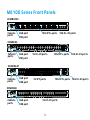
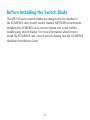
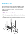
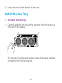
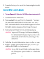
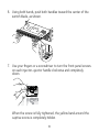
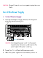
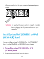
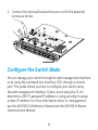
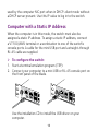
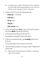
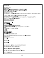
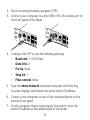
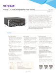
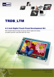
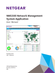
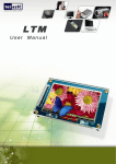
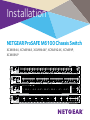
Installation
NETGEAR ProSAFE M6100 Chassis Switch
XCM8944, XCM8948, XCM8944F, XCM8924X, XCM89P,
XCM89UP
Contents
M6100 Series Front Panels....................................................................................... 3
Before Installing the Switch Blade............................................................................ 4
Install the Chassis......................................................................................................... 5
Install the Fan Tray....................................................................................................... 6
Install the Switch Blade............................................................................................... 7
Install the Power Supply............................................................................................. 9
Install Optional PoE (XCM89P) or UPoE (XCM89UP) Board.........................10
Configure the Switch Blade.....................................................................................11
2
M6100 Series Front Panels
XCM8924X
Console
ports
OoB port
USB port
10G SFP+ ports 10G RJ-45 ports
XCM8944
Console
ports
OoB port
USB port
1G RJ-45 ports
OoB port
USB port
1G SFP ports
10G SFP+ ports 10G RJ-45 ports
XCM8944F
Console
ports
10G SFP+ ports 10G RJ-45 ports
XCM8948
Console
ports
OoB port
USB port
1G RJ-45 ports
3
Before Installing the Switch Blade
The M6100 series switch blades are designed to be installed in
the XCM8903 rack-mount switch chassis. NETGEAR recommends
installing the XCM8903 rack-mount chassis into a rack before
installing any switch blades. For more information about how to
install the XCM8903 rack-mount switch chassis, see the XCM8903
Hardware Installation Guide.
4
Install the Chassis
You can either bracket-mount the chassis into a rack or install
the chassis using the included rails. For more information about
installing the chassis using rails, see the XCM8903 Hardware
Installation Guide.
¾¾ To bracket-mount the chassis:
1. Partially screw two of the included screws into the rack where
you want the bottom of the chassis to rest.
2. Rest the bottom of the chassis’s brackets on the two screws.
Supervisor
XCM8948
OOB
PWR
/
Status
Reset
Console
USB
1
2
3
4
5
6
7
8
9
10
11
PoE (Max
60W
12
per port):
Off =
13
no PD
14
Green
15
= PoE
16
powered
Yellow
17
= PoE
18
fault
19
RJ45
20
SPD/Link/Act
21
Mode:
22
Green
= link
23
at 1G
24
Yellow
= Link
25
at 10/100M
26
Blink
27
= ACT
28
29
30
31
32
33
34
35
36
37
38
39
40
41
42
43
44
45
46
47
48
5
3. Screw the rest of the bracket to the rack.
Install the Fan Tray
¾¾ To install the fan tray:
1. Carefully slide the fan tray all the way into the fan tray bay at
the rear of the chassis.
The fan tray is connected to power when it has been inserted
completely into the fan tray bay.
6
2. Screw the fan tray to the rear of the chassis using the included
screws.
Install the Switch Blade
¾¾ To install a switch blade in a M6100 series chassis switch:
1. Select a slot for the switch blade.
2. Remove a blank front panel from the chassis slot, if necessary.
Any unoccupied switch blade slot in the chassis must have a
blank faceplate installed to ensure satisfactory protection from
EMI and to maintain adequate airflow through the chassis.
3. Remove the switch blade from the antistatic packaging.
CAUTION:  To prevent ESD damage, hold the switch blade by
the metal rail and front panel only. Never touch the
components on the PCB or the pins on any of the
connectors.
4. Verify that the switch blade injector-ejector handles are open.
5. Keep the injector-ejector handles in the open position as you
slide the switch blade into the chassis slot.
CAUTION:  Do not slide the switch blade into the open chassis
slot if the injector-ejector handles are in the latched
position.
7
6. Using both hands, push both handles toward the center of the
switch blade, as shown.
Supervisor
XCM8
948
OOB
PWR
/
Status
Reset
Console
USB
1
2
3
4
5
6
7
8
9
10
11
PoE (Max
60W
12
per port):
Off =
13
no PD
14
Green
15
= PoE
16
powered
Yellow
17
= PoE
18
fault
19
RJ45
20
SPD/Link/Act
21
Mode:
22
Green
= link
23
at 1G
24
Yellow
= Link
25
at 10/100M
26
Blink
27
= ACT
28
29
30
31
32
33
34
35
36
37
38
39
40
41
42
43
44
45
46
47
48
7. Use your fingers or a screwdriver to turn the front panel screws
on each injector-ejector handle clockwise and completely
down.
When the screw is fully tightened, the yellow band around the
captive screw is completely hidden.
8
CAUTION:  Be careful to avoid over torquing and stripping the screw
heads.
Install the Power Supply
¾¾ To install the power supply:
1. Carefully slide the power supply all the way into the power
supply bay until it clicks into place.
Locking handle
CAUTION:  Do not slam the power supply into the system
backplane. Use the locking handle to secure the
power supply in the power supply bay.
2. Repeat Step 1 to install each additional power supply.
3. After all the power supplies have been installed, connect an
9
AC power cord to the AC input connector below each power
supply.
WARNING:  Be sure that the source outlet is properly grounded
before plugging the AC power cord into the input
connector.
Install Optional PoE (XCM89P) or UPoE
(XCM89UP) Board
You can install an optional PoE (XCM89P) or UPoE (XCM89UP)
board into the XCM8944 and XCM8948 switch blades.
¾¾ To install the optional PoE (XCM89P) or UPoE
(XCM89UP) board:
1. Remove the switch blade from the chassis.
10
2. Connect the optional board and secure it with the attached
screws as shown.
Configure the Switch Blade
You can manage your switch through its web management interface
or by using the command-line interface (CLI) through a console
port. This guide shows you how to configure your switch using
the web management interface. It also covers using the CLI to
determine a DHCP-assigned IP address or using ezconfig to assign
a static IP address. For more information about CLI management,
see the M6100 CLI Reference Manual and the M6100 Software
Administration Manual.
11
When configuring your switch, connect your switch to one of the
numbered ports on the switch’s front panel. Do not connect to the
Out-of-Band (OoB) port for initial switch configuration.
Note:  Use the OoB port to manage the switch only after the switch
has been configured for your network. For more information
about switch management using the OoB port, see the M6100
CLI Reference Manual and the M6100 Software Administration
Manual.
To configure your switch using web management, use one of the
following procedures, depending on how your Windows computer is
set up:
• Computer is in DHCP client mode without DHCP server.
• Computer uses a static IP address.
• Computer is in DHCP client mode with DHCP server.
Computer in DHCP Client Mode Without a DHCP
Server
The switch assumes a default IP address of 169.254.100.100 and
a subnet mask of 255.255.0.0. The switch is in the same subnet
12
used by the computer NIC port when in DHCP-client mode without
a DHCP server present. Use this IP value to log in to the switch.
Computer with a Static IP Address
When the computer is in this mode, the switch must also be
assigned a static IP address. To assign a static IP address, connect
a VT100/ANSI terminal or a workstation to one of the switch’s
console ports. A cable for the mini USB port and a straight-through
RJ-45 cable are supplied.
¾¾ To configure the switch:
1. Start a terminal emulation program (TEP).
2. Connect your computer to a mini USB or RJ-45 console port on
the front panel of the blade.
Use the installation CD to install the USB driver on your
computer.
13
Note:  You might need to install the USB serial port driver available on
the CD included with the package before you can use the mini
USB port on the computer to connect to the switch.
3. Configure the TEP to use the following settings:
• Baud rate. 115200 bps
• Data bits. 8
• Parity. None
• Stop bit. 1
• Flow control. None
4. At the command prompt User:, log in to the switch using the
user name admin and press the Enter key.
5. At the password prompt press the Enter key.
No password is required for initial configuration.
6. At the next command prompt, type ezconfig and press the
Enter key.
The ezconfig utility is now running on the switch.
7. Use the following example to set up your static IP address and
subnet mask.
Note:  Make sure that the selected switch IP address is in that same
subnet as the computer.
14
15
8. Connect your computer to one of the numbered ports on the
switch’s front panel.
9. Enter the IP address you configured in the address field of a
browser.
A login screen displays.
10.Enter admin for the user name and leave the password field
blank.
11.Click the Login button.
The system information screen displays.
12.Configure the switch for your network.
For more information on configuration settings and options, see
the M6100 Software Administration Guide.
Computer in DHCP Client Mode with a DHCP
Server
By default, the switch is configured as a DHCP client to obtain its IP
address from a DHCP server in the connected network. You must
access the switch from either the mini USB or RJ-45 console port.
¾¾ To configure the switch:
1. Make sure that the switch is connected to a DHCP server.
16
2. Start a terminal emulation program (TEP).
3. Connect your computer to a mini USB or RJ-45 console port on
the front panel of the blade.
4. Configure the TEP to use the following settings:
• Baud rate. 115200 bps
• Data bits. 8
• Parity. None
• Stop bit. 1
• Flow control. None
5. Type the show network command and press the Enter key.
A screen displays that shows the active switch IP address.
6. Connect your computer to one of the numbered ports on the
switch’s front panel.
7. On the computer that is connected to the switch, enter the
switch IP address in the address field of a browser.
17
A login screen displays.
8. Enter admin for the user name and leave the password field
blank.
9. Click the Login button.
The system information screen displays.
10.Configure the switch for your network.
For more information about configuration settings and options,
see the M6100 Software Administration Guide.
18
19
Technical Support
Thank you for selecting NETGEAR products. After installing your device, locate the serial
number on the label of your product and use it to register your product at
https://my.netgear.com. You must register your product before you can use NETGEAR
telephone support. NETGEAR recommends registering your product through the
NETGEAR website.
To contact NETGEAR for support, go to http://support.netgear.com/general/contact
or call (US only) 1-888-NETGEAR. In other countries, visit
http://support.netgear.com/general/contact/default.aspx for phone numbers.
For product updates and web support, visit http://support.netgear.com.
NETGEAR recommends that you use only the official NETGEAR support resources.
You can get the user manual online at
http://downloadcenter.netgear.com or through a link in the product’s user interface.
Trademarks
NETGEAR, the NETGEAR logo, and Connect with Innovation are trademarks and/or
registered trademarks of NETGEAR, Inc. and/or its subsidiaries in the United States and/
or other countries. Information is subject to change without notice. © NETGEAR, Inc. All
rights reserved.
Compliance
For the current EU Declaration of Conformity, visit:
http://support.netgear.com/app/answers/detail/a_id/11621/.
For regulatory compliance information, visit:
http://www.netgear.com/about/regulatory/.
August 2014
NETGEAR, Inc.
350 East Plumeria Drive
San Jose, CA 95134, USA