1
MOTOMAN
MOTOMAN XRC
USERS’S MANUAL
FDDWIN32 version 4.00
Upon receipt of the product and prior to initial operation, read these instructions thoroughly,
and retain for future reference.
MOTOMAN ROBOTICS EUROPE
A subsidiary of YASKAWA Electric Corporation
MANUAL NO. MRS55000
MOTOMAN ROBOTICS EUROPE
Reference list
Basic Operator’s Manual
Windows User’s Manual
This manual only show how to use FDDWIN32 together with robot
controller type: MOTOMAN XRC.
To connect to MRC or ERC controllers, see separate document
Revision
991125
First release of this manual
MOTOMAN ROBOTICS EUROPE
User’s manual FDDWIN32
Created: 99-10-29 Revised: 99-11-01
Page: 3
Doc. name: Mrs55000TOC.fm
1. General ................................................................. 5
Copyright
FDD-kit
❏ FDD-kit comprises
❏ FDD-Kit does not comprise
❏ Further you may have need for
Hardware and software demands
6
6
6
6
6
6
2. Software installation ............................................. 7
Installation
After installation
Uninstall
7
10
11
3. Communication setup ......................................... 13
Communication cable
I/O and IRQ setting
Directories and files
Communication setup
❏ In FDDWIN32
❏ Robot parameters
❏ Hardware connection to XRC
❏ Hardware key
13
13
14
15
15
15
16
16
4. FDD functions ..................................................... 17
File menu
❏ Select Directory
❏ Display File Contents
❏ Create directory
❏ Overwrite
Select language
Help
17
17
17
17
17
18
19
5. Program structure ............................................... 20
Files
Commands
20
21
6. Program running ................................................. 22
File management
Start software
Running from the robot
❏ Main menu för FDD communication
❏ Data that can be saved and save destination file names
Select unit
❏ Selecting a memory unit
Load
❏ Loading the job
❏ Loading files
Save
❏ Saving the job
❏ File saving
❏ Saving the CMOS data
❏ Overwriting existing files
Verifying data
❏ Verifying the job
❏ Verifying the condition file / universal data
23
24
25
25
25
29
29
30
30
31
33
33
34
36
38
39
39
41
MOTOMAN ROBOTICS EUROPE
Page: 4
Users’s manual FDDWIN32
Created: 99-10-29 Revised: 99-11-01
Doc. name: Mrs55000TOC.fm
Deleting files
❏ Delete the job
❏ Delete the file
❏ Job selection mode
Switch select mode
❏ How to select job and data files
Open a robot job
❏ View Header
❏ View Position
❏ View Instruction
❏ Line Sum
❏ Step Sum
Editing a language file
Create a new language file
43
43
44
45
47
47
49
50
50
50
50
50
51
52
7. Trouble shooting ................................................. 53
❏
❏
❏
❏
❏
Port setting not correct / not done!
Hardware key missing!
Communication disabled
No file was marked!
Warning at uninstall sequence
53
53
53
53
53
8. Windows NT ....................................................... 54
9. FDD-version ....................................................... 54
Manufacturer
54
MOTOMAN ROBOTICS EUROPE
User’s manual FDDWIN32
Created: 96-01-31 Revised: 99-11-25
Page: 5
Doc. name: Mrs55000-ch1.fm
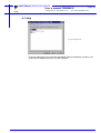
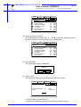
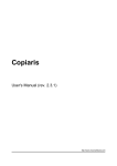
FDD for Windows (32-bit)
Valid for FDD for Windows, version 4.00 (Motoman part No. 441108-99).
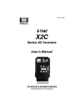
Fig.1
Main screen
1. General
FDD is a 32-bit PC-software.
The purpose with FDD is....
✔ One way communication from up to four MOTOMAN robots to one PC.
✔ Connection to ERC, MRC and XRC robot controllers.
✔ Replaces disk drives type FC1 / FC2.
✔ Expanded storage area for robot jobs in the PC.
✔ Editing the robot job is not possible by this program.
✔ This is a multi language version of FDD which gives you the facility to switch
between 11 languages and even create new language files.
For more basic information about installation and handling of the
software, icons, menu bars, etc. refer to the operator’s manual for
Windows 95/98 or Windows NT.
✔ This manual shall always be available to operator.
✔ This User’s Manual comprises information about
✔ Installation / Setup / Handling / operation for XRC robot controller
✔ Text written in BOLD letters means command, icon or button.
✔ Text written in ITALIC means text shown on display.
MOTOMAN ROBOTICS EUROPE
Page: 6
Users’s manual FDDWIN32
Created: 96-01-31 Revised: 99-11-25
Doc. name: Mrs55000-ch1.fm
Copyright
1.1 Copyright
The diskettes for FDD-program may not be copied or imparted to a third party nor
be used for an unauthorized purpose. Copies may be done only for own backup.
This manual may not be copied or imparted to a third party nor be used for an
unauthorized purpose.
1.2 FDD-kit
■ FDD-kit comprises
✔ Diskettes (for FDD and NT drivers) or CD-ROM
✔ One hardware key
✔ One manual
✔ One registration card
■ FDD-Kit does not comprise
✔ Cables Motoman part No 347359-xx (xx =length code)
✔ Adaptors
■ Further you may have need for
✔ Programming manual for your robot controller.
✔ Operator’s manual for Windows 95/98 or Windows NT.
1.3 Hardware and software demands
✔ One PC type 486 or better, 16 Mb RAM, 2 Mb disk space.
✔ 3,5”-diskette station, 1,44 Mb.
✔ Colour monitor (not necessary).
✔ Windows 95/98 or Windows NT.
✔ If three or four robots are to be connected, the computer must be equipped
with an extra board including two extra Com-ports.
✔ MOTOMAN XRC robot controller.
✔ RS232 adaptor, 9-pole to 25-pole.
✔ Protective hood, if the PC is installed in the workshop.
MOTOMAN ROBOTICS EUROPE
Software installation
Installation
Created: 96-01-31 Revised: 99-11-23
Page: 7
Doc. name: Software-installation.fm
2. Software installation
Note
This chapter shows a general installation phase of any software. In this example
the software FDDWIN is installed. Select the right software by choosing the
appropriate software name.
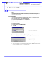
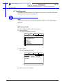
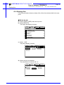
2.1 Installation
There are three ways to start installation of this software, all will give the same
result. The most common way is described below.
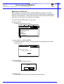
a) Put the first diskette named #1 in the disk-drive.
b) Click on the Start button on the menu-bar.
c) Choose Run from the menu.
d) Browse to drive A:\
e) Choose the file named SETUP.EXE
f) Click OK.
Fig.1 Choose installation file
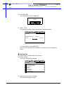
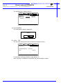
g) Choose OK and the installation guide will start.
h) You can quit the installation att any time by clicking the Cancel-button and
then confirm by Yes-button.
Fig.2 You can cancel
installation at any time
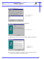
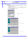
i) Mark the language you want to use during installation. Note! This will not influence the language you use in FDDWIN32 later.
MOTOMAN ROBOTICS EUROPE
Software installation
Page: 8
Created: 96-01-31 Revised: 99-11-23
Installation
Doc. name: Software-installation.fm
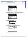
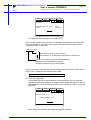
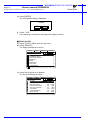
j) Click on the OK-button.
Fig.3 Language selection
during installation
k) Pass this information screen by clicking the Next-button.
Fig.4 Information screen
l) Read through the license agreement and accept by clicking on the Next-button.
Fig.5 License
agreement. Accept by
clicking Next.
m) Set directory for FDDWIN32. It’s advisable to install the software in the directory which is set as default by the installation guide.
MOTOMAN ROBOTICS EUROPE
Software installation
Installation
Created: 96-01-31 Revised: 99-11-23
Page: 9
Doc. name: Software-installation.fm
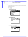
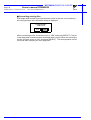
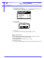
n) Accept by clicking Next-button.
Fig.6 Choose
directory
o) Accept installation process by clicking Next-button.
Fig.7 Start installation
p) Installation starts.
Fig.8 Installation
progress counter
q) After some time you are told to enter disk #2/2.
r) Insert disk and click on OK-button.
Fig.9 Insert disk #2
s) The installation is finished and the last screen appears.
MOTOMAN ROBOTICS EUROPE
Software installation
Page: 10
Created: 96-01-31 Revised: 99-11-23
After installation
Doc. name: Software-installation.fm
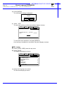
t) Accept installation by clicking the Finish-button.
Fig.10 Installation
complete
u) Before it is possible to run the software, the hardware key must be installed on
the parallel port.
2.2 After installation
After installation, fill in and return the registration card to Motoman
Robotics AB.
During installation the main directory is automatically created and all necessary
files are installed in the specified drive.
In the end of the setup a program group (MOTOMAN) and a icon is created. To
start FDD for Windows just double-click on the Start Menu.
If you want to create a shortcut to FDDWIN32, see Windows manual for further
information
MOTOMAN ROBOTICS EUROPE
Software installation
Uninstall
Page: 11
Created: 96-01-31 Revised: 99-11-23
Doc. name: Software-installation.fm
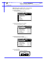
2.3 Uninstall
As in all WIN95/NT softwares there are an uninstall facility if you want to remove
the software from the hard disk.
a) Start the Control panel from the start menu. Select Add/Remove button from
the menu.
b) Mark the line FDDWIN32 from the menu.
c) Click Add/Remove button.
Fig.11 Mark the FDDWIN32
software
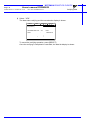
d) Activate uninstall guide by Next-button.
Fig.12 Automatic uninstall
e) End the operation by clicking the Finish-button.
Fig.13 Uninstall
MOTOMAN ROBOTICS EUROPE
Page: 12
Created: 96-01-31 Revised: 99-11-23
Software installation
Doc. name: Software-installation.fm
Uninstall
MOTOMAN ROBOTICS EUROPE
User’s manual FDDWIN32
Communication cable
Created: 96-01-31 Revised: 99-11-25
Page: 13
Doc. name: Mrs55000-ch3.fm
3. Communication setup
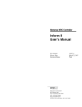
3.1 Communication cable
Communication between PC and robot controller via RS232C-serial interface.
Cable length max. 15 m to each robot-controller. It is possible to use short-distance-modem if the distance is longer.
Com1 and Com3 are 9-pole plugs.
Com2 and Com4 are 25-pole plugs
Cable layout, see figure.
(Ground / shield)
DCD 1
RX 2
TX 3
DTR 4
GND 5
6
1
2
3
4
DCD
RX
TX
DTR
5 GND
6
7 RTS
RTS 7
CTS 8
8 CTS
9 (RI)
FG 9
Cabel
XRC 9-pole
PC 9-pole
Fig.15 Cabel P/N 347359
3.2 I/O and IRQ setting
For communication the following settings is recommended in the PC.
port
I/O
IRQ
Com1
03F8
4
Com2
02F8
3
Com3
03E8
5
Com4
02E8
9
Setting of I/O and IRQ is made by software in Windows under the icon Control
panel / ports.
This is the normal setting for Com1 and Com2. For the extra board (Com3 and
Com4) it could be needed to move jumpers direct on the board.
MOTOMAN ROBOTICS EUROPE
Page: 14
Users’s manual FDDWIN32
Created: 96-01-31 Revised: 99-11-25
Directories and files
Doc. name: Mrs55000-ch3.fm
3.3 Directories and files
Together with this manual two installation diskettes are included. These diskettes
contains the FDD-program in compressed form.
The license is valid for communication with up to four robots from one PC. The
hardware key can only be use on one PC at a time.
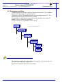
It is advisable to create separate directories for the robot jobs, name them for
example; robot-1, robot-2, etc, see figure.
For more information, see Windows user’s manual.
C:\
Fig.16 Directory layout
Program
Motoman
Fddwin32
robot-1
robot-2
Files loaded into the PC file system will get an extension of .jbr .jbi .dat .prm .cnd
.lst .sys or .hex dependinng on typ of file.
See further information at the end of this manual.
MOTOMAN ROBOTICS EUROPE
User’s manual FDDWIN32
Communication setup
Created: 96-01-31 Revised: 99-11-25
Page: 15
Doc. name: Mrs55000-ch3.fm
3.4 Communication setup
■ In FDDWIN32
The communication protocol is very special, (for more information see
MOTOMAN XRC computer communication User’s manual.)
Communication parameters in the PC shall be set as follows:
Baud rate
4800
Data bits
8
Stop bits
1
Parity check
2 (even)
a) Click on [File] in the menu.
b) Click on [Port setup].
A menu is displayed, normally it’s not necessary to make any changes in this settings.
c) When the settings are ok, click on [OK].
Fig.17 Port setting menu
■ Robot parameters
To establish communication between XRC robot controller and PC some parameters have to be set.
Contact your MOTOMAN-representative if in doubt.
Type
XRC
Initial setting
Data bit
Stop bit
Parity
Baud rate
Response timer
Text end mon.
ENQ retry
Data retry
Disk size
Job overwrite
RS000= (* Std. port #1)
RS50=8
RS51=0
RS52=2
RS53=6
RS54=0
RS55=0
RS56=0
RS57=0
RS58=3
RS59=0
0
8
0
2
6
0
0
0
0
3
0
MOTOMAN ROBOTICS EUROPE
Page: 16
Users’s manual FDDWIN32
Created: 96-01-31 Revised: 99-11-25
Communication setup
Doc. name: Mrs55000-ch3.fm
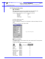
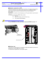
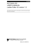
■ Hardware connection to XRC
The XRC controller has two 9-pole cable connectors. One 9-pole socket underneath the lid at the short end of the programming pendant = FDD Port (CN01).
And a 9-pole socket inside XRC located at CPU unit (XCP01-board) =
Std. port #1.
The FDD port is used for normal temporary use. The port inside is used for stationary use.
(*) Settings for parameter RS000 (Std. port #1):
0 = Not used
2 = Data transmission protocol (PC as host)
3 = FC1 protocol (FDD software)
To run FDDWIN32 via Std. port #1 you must set RS000 to value ”3”
JZNC-XRK01
YASNAC
INPUT
220-230V AC
50/60Hz
2,1 A
FDD port
(normally used)
SOURCE
POWER
ON
+5V
+24V
OHT
THIUM
Standard port #1
ALM
■ Hardware key
To be able to run the program it is necessary to apply the hardware key. Mount the
hardware key on the parallel port of the PC.
For Windows NT applications, see separate chapter.
MOTOMAN ROBOTICS EUROPE
User’s manual FDDWIN32
File menu
Created: 96-01-31 Revised: 99-11-25
Page: 17
Doc. name: Mrs55000-ch3.fm
4. FDD functions
Fig.18 FDD setting
4.1 File menu
■ Select Directory
From this menu you select to which directory you will copy your robot files.
■ Display File Contents
By first selecting a file in the File Information window and then use this command, the choosen file is opened in Windows Notepad.
You can also start Notepad by doubble-click on the file directly.
■ Create directory
A new directory can be created direct from the Select Directory menu.
Just write the new name in the ”Directory:”-box in the right place and click on the
Create-button. The Windows system can handle (max 255 characters).
■ Overwrite
Under this menu it’s possible to set the basic functions for file-copy.
If Overwrite is marked when the files are sent from the robot controller the files in
the user directory will be written over without warning!
If Overwrite is not marked an alarm messages will be sent if the file already exists
in the user directory. Erase the file or switch to another user directory.
MOTOMAN ROBOTICS EUROPE
Users’s manual FDDWIN32
Page: 18
Created: 96-01-31 Revised: 99-11-25
Doc. name: Mrs55000-ch3.fm
Select language
4.2 Select language
Every time you start FDD for Windows version 4.00 you will be given the facility to
choose language for menues and commands.
Fig.19 Multi language
Choose language and then click on the OK button.
Note!
Japanees language can’t be displayed in an European computer.
It is even possible to correct and change each word or to create a totally new language file, see separate chapter in this document.
If you don’t want to display this window every time you start the FDD software, just
mark the line ”Ignore language selection at program start”.
You also have the facility to change the font in the menues. If the ”Default Fonts
will be used” is marked MS Sans serif will be used.
If you unmark the funktion a dialogue box from Windows system will appear and
you have the facility to choose font (style).
MOTOMAN ROBOTICS EUROPE
User’s manual FDDWIN32
Help
Created: 96-01-31 Revised: 99-11-25
Page: 19
Doc. name: Mrs55000-ch3.fm
4.3 Help
Fig.20 Help menu
From the Help menu you get short information about commands, functions, etc.
which can be helpful when you run the software.
MOTOMAN ROBOTICS EUROPE
Users’s manual FDDWIN32
Page: 20
Created: 96-01-31 Revised: 99-11-25
Files
Doc. name: Mrs55000-ch3.fm
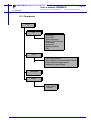
5. Program structure
FDD is a Windows based communication program for connection between a PC
and MOTOMAN industrial robots, controller type ERC, MRC or XRC.
5.1 Files
FC1.ini
Terminal
FDD
Main file
MOTOCOM32
.dll
Robot
controller
Keyboard
Fig.21 Data flow
FDD consists of one main file communicating with the user and controlling the
main functions. The main file is written in Visual Basic which is a Windows based
designer program. Therefore, the functions and the menus are the same as for
Windows.
FDD uses the colours set up for Windows, which can be set under the Windows
Control panel.
FDD also comprises a DII-file which supervise the communication between the
PC and the robot controller. The DII-file is written in Visual C++ and will be installed in the Win.ini-file.
FDD also comprises a fc1.ini-file in which information about main directory and
user directory is stored.
FDD for Windows is available in 11 languages:
-Swedish
-English
-French
-German
-Italian
-Finnish
-Norweigan
-Danish
(excluded)
-Spanish
-Portugese
(excluded)
-Japanese
MOTOMAN ROBOTICS EUROPE
User’s manual FDDWIN32
Commands
Created: 96-01-31 Revised: 99-11-25
Doc. name: Mrs55000-ch3.fm
5.2 Commands
FDD
File
Start FDD
Quit FDD
Select Directory
Display File Contents
Port Setup
Overwrite
Advanced Mode
Exit
View
View Job Contents
View Details of Communication Status
Clear Communication Status
Refresh to Latest Status
Language
Help
Help Topics
Version
Page: 21
MOTOMAN ROBOTICS EUROPE
Page: 22
Users’s manual FDDWIN32
Created: 96-01-31 Revised: 99-11-25
Doc. name: Mrs55000-ch3.fm
Commands
6. Program running
FDD-program is run (load and save files) from the programming pendant of the
controller. The command run from the PC is only for handling of the files in the
PC (move files, user directory and open files for printing etc.).
MOTOMAN ROBOTICS EUROPE
User’s manual FDDWIN32
File management
Created: 96-01-31 Revised: 99-11-25
Doc. name: Mrs55000-ch3.fm
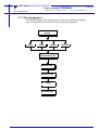
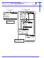
6.1 File management
The following diagram is an operation flow to show file transfer and management. The operation is performed with the programming pendant.
Select desired
device
LOAD
SAVE
VERIFY
Select data group
Select data
[EXECUTE]
Verify
Completion
DELETE
Page: 23
MOTOMAN ROBOTICS EUROPE
Page: 24
Users’s manual FDDWIN32
Created: 96-01-31 Revised: 99-11-25
Start software
Doc. name: Mrs55000-ch3.fm
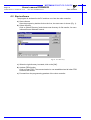
6.2 Start software
The program is activated in the PC and then run from the robot controller.
a) Start software
Start the program by double-click on the icon, the start menu is shown (Fig. 1).
b) Select directory
Click on [Select Directory] and choose user directory for file transfer, for more
information see Windows manual.
Fig.22 User directory
c) When the right directory is stated, click on the [OK].
d) Activate FDD function
Click on [Start FDD]. The communication is now established and all other FDD
functions are locked.
e) Proceed from the programming pendant of the robot controller.
MOTOMAN ROBOTICS EUROPE
User’s manual FDDWIN32
Running from the robot
Created: 96-01-31 Revised: 99-11-25
Page: 25
Doc. name: Mrs55000-ch3.fm
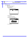
6.3 Running from the robot
■ Main menu för FDD communication
a) From the [TOP MENU] choose [FD/PC CARD].
b) Choose the appropriate task.
R1
L
LOAD
SAVE
VERIFY
DELETE
FORMAT
DEVICE
C
S
! Turn on servo power
1) LOAD
Copy files from the computer into the robot controller.
2) SAVE
Copy files from the robot controller into the computer.
3) VERIFY
Compare files in the robot controller with the files in computer. This should
always be done to secure correct data transmission.
4) DELETE
Delete files in the computer.
5) FORMAT
Not to be used when running FDDWIN32 to a computer.
6) DEVICE
Select device, FC1, FC2, PC Card, etc.
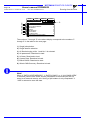
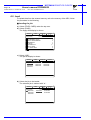
■ Data that can be saved and save destination file names
The floppy disk display is shown below. Data that can be saved are classified into
eight groups. The table on the next page lists the data of the eight groups. The
table also shows different file names provided for saving different types of data.
Data saved at an external memory unit can be reloaded into the memory of the
XRC. Data belonging to the data groups marked with “n” on the FD/PC CARD
display (shown below) have restrictions which apply to reloading into memory
because they include system-related information.
Note!
Refer to “YASNAC XRC Maintenance manual” for the method to reload into the
memory any data belonging to the data groups marked with “n“ on the FD/PC
CARD display,
MOTOMAN ROBOTICS EUROPE
Users’s manual FDDWIN32
Page: 26
Created: 96-01-31 Revised: 99-11-25
•
‚
ƒ
„
…
†
‡
ˆ
Doc. name: Mrs55000-ch3.fm
DATA
EDIT
DISPLAY
UTILITY
L
C S
FLOPPY DISK/PC CARD
R1
FC1(SAVE)
UN-USED MEM :0.457GB
JOB
8
FILE/GENERAL DATA
0
BATCH USER MEMORY
0
PARAMETER
AAA
1
I/O DATA
0
SYSTEM DATA
A
0
BATCH CMOSAAA
0
ALL CMOS AREA
0
! marked data cannot be loaded
Running from the robot
‰
The numbers • through ˆ in the above display correspond to the numbers •
through ˆ in the table on the next page.
1) Single job selection.
2) Single data file selection.
3) All files belonging to No. 1 and No. 2 is selected.
4) All parameters. Restricted to load.
5) I/O data. Restricted to load.
6) System Data. Restricted to load.
7) Batch CMOS. Restricted to load.
8) Whole CMOS memory. Restricted to load.
Note!
When ƒ “BATCH USER MEMORY”, ‡ “BATCH CMOS”, or ˆ “ALL CMOS AREA”
is selected, jobs are also saved, but the job headers of the saved jobs are not
saved to an external memory unit. Saving of job headers is only completed if •
“JOB” is selected to save the data.
MOTOMAN ROBOTICS EUROPE
User’s manual FDDWIN32
Running from the robot
Created: 96-01-31 Revised: 99-11-25
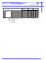
Data That Can Be Saved
File Name
(Saved Data)
ˆ ALL CMOS AREA
‡ BATCH CMOS
ƒ BATCH USER MEMORY
• JOB
Single job
ALLCMSxx.HEX
‚FILE/
GENERAL
DATA
CMOSxx.HEX
JOBxx.HEX
JOBNAME.JBI
Related job (Job+Condition)
JOBNAME.JBR
Tool data
TOOL.CND
Weaving data
WEAV.CND
User coordinate data
UFRAME.CND
Converted data
VAR.DAT
Arc start condition data
ARCSRT.CND
Arc end condition data
ARCEND.CND
Welder condition Assist Data
ARCSUP.DAT
Welder characteristic Data
WELDER.DAT
Welder char. definition data
WELDDUDEF.DAT
Shoch detection level data
SHOCKLVL.CND
Servo Gun Pressure Power
SPRESS.CND
Servo Gun Dry Spot Pres-
SPRESSCL.CND
Spot Gun Characteristic Data
SGUN.DAT
Spot Welder Characteristic Data SWELDER.DAT
Short/Full Open Position Data
„ PARAMETER BATCH
„ PARAME- Robot matching parameter
TER
… I/O DATA
STROKE.DAT
ALL.PRM
RC.PRM
System definition parameter
SD.PRM
Coordinate origin parameter
RO.PRM
System matching parameter
SC.PRM
ClO parameter
CIO.PRM
Function definition parameter
FD.PRM
Application parameter
AP.PRM
Transmission(general) parame-
RS.PRM
Sensor parameter
SE.PRM
Servo parameter
SV.PRM
Servo motor parameter
SVM.PRM
Operation Control Parameter
AMC.PRM
Servo Power Block Parameter
SVP.PRM
Motion Function Parameter
MF.PRM
Motion Transmission Parameter
RSM.PRM
PC Definition Parameter
PCD.PRM
Concurrent I/O program
CIOPRG.LST
I/O name data
IONAME.DAT
Page: 27
Doc. name: Mrs55000-ch3.fm
Save
Load
OPER EDIT
OPER EDIT
✔
✔
✔
✔
✔
✔
✔
✔
✔
✔
✔
✔
✔
✔
✔
✔
✔
✔
✔
✔
✔
✔
✔
✔
✔
✔
✔
✔
✔
✔
✔
✔
✔
✔
✔
✔
✔
✔
✔
✔
✔
✔
✔
✔
✔
✔
✔
✔
✔
✔
✔
✔
✔
✔
✔
✔
✔
✔
✔
✔
✔
✔
✔
✔
✔
✔
✔
✔
✔
✔
✔
✔
✔
✔
✔
✔
✔
✔
✸
✸
✔
✔
✔
✔
✔
✔
✔
✔
✔
✔
✔
✔
✔
✔
✔
✔
✔
✔
✸
✸
✸
✸
✸
✸
✸
✸
✸
✸
✸
✸
✸
✸
✸
✸
✸
✸
✸
✸
✸
✔
✔
✔
✔
✔
✔
✔
✔
✔
✔
✔
✔
✔
✔
✔
✔
✔
✔
✔
✔
✔
✔
✔
✔
✔
✔
✔
✔
✔
✔
✔
✔
✔
✔
✔
✔
✔
MOTOMAN ROBOTICS EUROPE
Users’s manual FDDWIN32
Page: 28
Created: 96-01-31 Revised: 99-11-25
Running from the robot
Doc. name: Mrs55000-ch3.fm
Data That Can Be Saved
File Name
(Saved Data)
Save
Load
OPER EDIT
†SYSTEM
DATA
User Word Registration
UWORD.DAT
SV monitor signals
SVMON.DAT
Variable name
VARNAME.DAT
Second home position
HOME2.DAT
Alarm history data
ALMHIST.DAT
Home position calibrating data
ABSO.DAT
System Information
SYSTEM.SYS
OPER : Operation Mode
EDIT : Edit Mode
✸ = Not possible
✔ = OK (possible)
✔
✔
✔
✔
✔
✔
✔
✔
✔
✔
✔
✔
✔
✔
OPER EDIT
✸
✸
✸
✸
✸
✸
✸
✔
✔
✔
✔
✔
✔
✔
MOTOMAN ROBOTICS EUROPE
User’s manual FDDWIN32
Select unit
Created: 96-01-31 Revised: 99-11-25
6.4 Select unit
■ Selecting a memory unit
a) Select [FD/PC CARD].
b) Select [DEVICE].
The device select display is shown.
DATA
EDIT
DISPLAY
FLOPPY DISK/PC CARD
R1
DEVICE
UTILITY
L
C
S
: FC1
!
c) Press [SELECT].
The select dialog is displayed.
d) In FDDWIN case, select >FC1<,
Move the cursor and press [SELECT].
DATA
EDIT
DISPLAY
FLOPPY DISK/PC CARD
R1
DEVICE
: FC1
FC1
FC2
!
e) Press [ENTER].
UTILITY
L
C
S
Page: 29
Doc. name: Mrs55000-ch3.fm
MOTOMAN ROBOTICS EUROPE
Users’s manual FDDWIN32
Page: 30
Created: 96-01-31 Revised: 99-11-25
Doc. name: Mrs55000-ch3.fm
Load
6.5 Load
To upload data from the external memory unit to the memory of the XRC, follow
the procedure in the following.
■ Loading the job
a) Select {FD/PC CARD} under the top men.
b) Select {LOAD}.
The floppy disk display is shown.
DATA
EDIT
DISPLAY
UTILITY
L
C S
FLOPPY DISK/PC CARD
R1
FC2(LOAD)
UN-USED MEM :123.4 KB
JOB
7
FILE/GENERAL DATA
0
BATCH USER MEMORY
0
PARAMETER
1
I/O DATA
0
SYSTEM DATA
0
BATCH CMOSAAA
0
ALL CMOS AREA
0
! marked data cannot be loaded
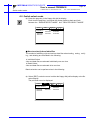
c) Select “JOB”.
The job list display is shown.
DATA
EDIT
DISPLAY
UTILITY
L
C S
FLOPPY DISK/PC CARD
R1
FC2(LOAD)
SINGLE
NO.:7
TEST0001
TEST0002
TEST0003
TEST0004
TEST0005
TEST0006
TEST0007
!
d) Select the job to be loaded.
The selected job is marked with “«“.
DATA
EDIT
DISPLAY
UTILITY
L
C S
FLOPPY DISK/PC CARD
R1
FC2(LOAD)
SINGLE
NO.:7
TEST0001
TEST0002
TEST0003
TEST0004
TEST0005
TEST0006
TEST0007
!
MOTOMAN ROBOTICS EUROPE
User’s manual FDDWIN32
Load
Created: 96-01-31 Revised: 99-11-25
Page: 31
Doc. name: Mrs55000-ch3.fm
e) Press [ENTER].
The confirmation dialog is displayed.
Load?
YES
NO
f) Select “YES”.
The job starts loading, and the transmission display is shown.
DATA
EDIT
DISPLAY
FLOPPY DISK/PC CARD
R1
FC2(LOAD)
UTILITY
L
C
S
TRANSMITTED FILE : TEST0001
REST
:
50 BYTE
STOP
!
To cancel loading, press [SELECT].
Once the load operation is completed or cancelled, the job list display is
shown.
■ Loading files
a) Select {FD/PC CARD} under the top menu.
b) Select {LOAD}.
The floppy disk display is shown.
DATA
EDIT
DISPLAY
UTILITY
L
C S
FLOPPY DISK/PC CARD
R1
FC2(LOAD)
UN-USED MEM :123.4 KB
JOB
8
FILE/GENERAL DATA
0
BATCH USER MEMORY
0
PARAMETER
AAA
1
I/O DATA
0
SYSTEM DATA
A
0
BATCH CMOSAAA
0
ALL CMOS AREA
0
! marked data cannot be loaded
c) Select the file group to be loaded.
The file select display is shown.
MOTOMAN ROBOTICS EUROPE
Page: 32
Users’s manual FDDWIN32
Created: 96-01-31 Revised: 99-11-25
Load
Doc. name: Mrs55000-ch3.fm
DATA
EDIT
DISPLAY
R1
FLOPPY DISK/PC CARD
FC2(LOAD)
BATCH PARAMETER
ROBOT MATCH PRMTR
SYS DEF PRMTR
COORD ORG PRMTR
SYS MATCH PRMTR
CIO PRMTR
FCTN DEF PRMTR
APPLI PRMTR
!
UTILITY
L
C
ALL
RC
SD
RO
SC
CIO
FD
AP
S
.PRM
.PRM
.PRM
.PRM
.PRM
.PRM
.PRM
.PRM
Select the file to be loaded.
The selected data is marked with “«“. The “l” mark in the display shows the
file which exists in the external memory unit (floppy disk).
DATA
EDIT
DISPLAY
FLOPPY DISK/PC CARD
R1
FC2(LOAD)
BATCH PARAMETER
ROBOT MATCH PRMTR
SYS DEF PRMTR
COORD ORG PRMTR
SYS MATCH PRMTR
CIO PRMTR
FCTN DEF PRMTR
APPLI PRMTR
!
UTILITY
L
C
ALL
RC
SD
RO
SC
CIO
FD
AP
S
.PRM
.PRM
.PRM
.PRM
.PRM
.PRM
.PRM
.PRM
Press [ENTER].
The confirmation dialog is displayed.
Load?
YES
NO
d) Select “YES”.
The data starts loading, and the transmission display is shown.
DATA
EDIT
DISPLAY
FLOPPY DISK/PC CARD
R1
FC2(LOAD)
TRANSMITTED FILE : ALL
REST
:
UTILITY
L
C
S
.PRM
19968 BYTE
STOP
!
To cancel loading, press [SELECT].
Once loading is completed or cancelled, the file select display is shown.
MOTOMAN ROBOTICS EUROPE
User’s manual FDDWIN32
Save
Created: 96-01-31 Revised: 99-11-25
Page: 33
Doc. name: Mrs55000-ch3.fm
6.6 Save
To download data from the memory of the XRC to the external memory unit, perform the following procedure.
■ Saving the job
a) Select {FD/PC CARD} under the top menu.
b) Select {SAVE}.
The floppy disk display is shown.
DATA
EDIT
DISPLAY
UTILITY
L
C S
FLOPPY DISK/PC CARD
R1
FC2(SAVE)
UN-USED MEM :123.4 KB
JOB
8
FILE/GENERAL DATA
0
BATCH USER MEMORY
0
PARAMETER
AAA
1
I/O DATA
0
SYSTEM DATA
A
0
BATCH CMOS AAA
0
ALL CMOS AREA
0
! marked data cannot be loaded
c) Select “JOB”.
The job list display is shown.
DATA
EDIT
DISPLAY
UTILITY
L
C S
FLOPPY DISK/PC CARD
R1
FC2(SAVE)
SINGLE
NO.:7
TEST0001
TEST0002
TEST0003
TEST0004
TEST0005
TEST0006
TEST0007
!
d) Select the job to be saved.
The selected job is marked with “«“.
DATA
EDIT
DISPLAY
UTILITY
L
C S
FLOPPY DISK/PC CARD
R1
FC2(SAVE)
SINGLE
NO.:7
TEST0001
TEST0002
TEST0003
TEST0004
TEST0005
TEST0006
TEST0007
!
MOTOMAN ROBOTICS EUROPE
Page: 34
Users’s manual FDDWIN32
Created: 96-01-31 Revised: 99-11-25
Save
Doc. name: Mrs55000-ch3.fm
e) Press [ENTER].
The confirmation dialog is displayed.
Save?
YES
NO
f) Select “YES”.
The job starts saving, and the transmission display is shown.
DATA
EDIT
DISPLAY
FLOPPY DISK/PC CARD
R1
FC2(SAVE)
UTILITY
L
C
S
TRANSMITTED FILE : TEST0001
REST
:
50 BYTE
STOP
!
To cancel the save operation, and press [SELECT].
Once saving is completed or cancelled, the job list display is shown.
■ File saving
a) Select {FD/PC CARD} under the top menu.
b) Select {SAVE}.
The floppy disk display is shown.
DATA
EDIT
DISPLAY
UTILITY
L
C S
FLOPPY DISK/PC CARD
R1
FC2(SAVE)
UN-USED MEM :123.4 KB
JOB
8
FILE/GENERAL DATA
0
BATCH USER MEMORY
0
PARAMETER
AAA
1
I/O DATA
0
SYSTEM DATA
A
0
BATCH CMOSAAA
0
ALL CMOS AREA
0
! marked data cannot be loaded
c) Select the file group to be saved.
The file select display is shown.
MOTOMAN ROBOTICS EUROPE
User’s manual FDDWIN32
Save
Created: 96-01-31 Revised: 99-11-25
DATA
EDIT
DISPLAY
FLOPPY DISK/PC CARD
R1
FC2(SAVE)
BATCH PARAMETER
ROBOT MATCH PRMTR
SYS DEF PRMTR
COORD ORG PRMTR
SYS MATCH PRMTR
CIO PRMTR
FCTN DEF PRMTR
APPLI PRMTR
!
Page: 35
Doc. name: Mrs55000-ch3.fm
UTILITY
L
C
ALL
RC
SD
RO
SC
CIO
FD
AP
S
.PRM
.PRM
.PRM
.PRM
.PRM
.PRM
.PRM
.PRM
d) Select the file to be saved.
The selected data is marked with “«“. The “l” mark in the display shows the
file which exists in the external memory unit (floppy disk).
DATA
EDIT
DISPLAY
FLOPPY DISK/PC CARD
R1
FC2(SAVE)
BATCH PARAMETER
ROBOT MATCH PRMTR
SYS DEF PRMTR
COORD ORG PRMTR
SYS MATCH PRMTR
CIO PRMTR
FCTN DEF PRMTR
APPLI PRMTR
!
UTILITY
L
C
ALL
RC
SD
RO
SC
CIO
FD
AP
S
.PRM
.PRM
.PRM
.PRM
.PRM
.PRM
.PRM
.PRM
e) Press [ENTER].
The confirmation dialog is displayed.
Save?
YES
NO
f) Select “YES”.
The data starts saving and the transmission display is shown.
DATA
EDIT
DISPLAY
FLOPPY DISK/PC CARD
R1
FC2(SAVE)
TRANSMITTED FILE : ALL
REST
:
UTILITY
L
C
S
.PRM
19968 BYTE
STOP
!
To cancel loading, press [SELECT].
If loading is completed or canceled, the file select display is shown.
MOTOMAN ROBOTICS EUROPE
Page: 36
Users’s manual FDDWIN32
Created: 96-01-31 Revised: 99-11-25
Save
Doc. name: Mrs55000-ch3.fm
■ Saving the CMOS data
To save all user’s programs (BATCH USER MEMORY), all data in the CMOS
(BATCH CMOS), or all data in the CMOS area (ALL CMOS AREA), a single floppy
disk may not be sufficient. In that case, the operator must provide another floppy
disk when so instructed by a message on the display.
a) Select {FD/PC CARD} under the top menu.
b) Select {SAVE}.
The floppy disk display is shown.
DATA
EDIT
DISPLAY
UTILITY
L
C S
FLOPPY DISK/PC CARD
R1
FC2(SAVE)
UN-USED MEM :123.4 KB
JOB
8
FILE/GENERAL DATA
0
BATCH USER MEMORY
0
PARAMETER
AAA
1
I/O DATA
0
SYSTEM DATA
A
0
BATCH CMOSAAA
0
ALL CMOS AREA
0
! marked data cannot be loaded
c) Select “BATCH USER MEMORY”.
The following display is shown. Please insert the first floppy disk in the external memory unit.
DATA
EDIT
DISPLAY
FLOPPY DISK/PC CARD
R1
UTILITY
L
C
S
INSERT FLOPPY NO. 1
USABLE MEMORY: 100 %
EXEC
!
d) Select “EXEC”.
The confirmation dialog is shown.
Save?
YES
NO
e) Select “YES”.
The file starts saving, and the transmission display is shown.
MOTOMAN ROBOTICS EUROPE
User’s manual FDDWIN32
Save
Created: 96-01-31 Revised: 99-11-25
DATA
EDIT
DISPLAY
FLOPPY DISK/PC CARD
R1
FC2(SAVE)
TRANSMITTED FILE : JOB1
REST
:
Page: 37
Doc. name: Mrs55000-ch3.fm
UTILITY
L
C
S
.HEX
2174 BYTE
STOP
!
To cancel the save operation, press [SELECT].
Files can be created as long as there is still space remaining on the floppy disk.
Each file created on the floppy disk is given a file name that includes a serial
number (in order of creation).
JOB 1E. HEX
1
2
Serial numbers in the order of creation.
The chracter “E” is attached to the name of the last file.
E
J0B:all user’s programs (BATCH USER MEMORY)
CMOS:all data in CMOS(BATCH CMOS)
ALCMS:all CMOS area (ALL CMOS AREA)
An error will occur if the operator inserts a floppy disk having the unused area of
2KB or less. Replace it with another floppy disk.
!Not enough memory
f) Insert the floppy disk.
If more data need to be saved when the first floppy disk is full, a message
appears to prompt the operator to supply another floppy disk. Remove the current floppy disk, insert another one, and move the cursor to “EXEC” and press
[SELECT].
DATA
EDIT
DISPLAY
FLOPPY DISK/PC CARD
R1
UTILITY
L
C
S
INSERT FLOPPY NO. 2
USABLE MEMORY: 83 %
EXEC
!
After saving is completed, the floppy disk display is shown.
MOTOMAN ROBOTICS EUROPE
Page: 38
Users’s manual FDDWIN32
Created: 96-01-31 Revised: 99-11-25
Doc. name: Mrs55000-ch3.fm
Save
■ Overwriting existing files
If the floppy disk contains a file with the same name as the one to be created by
the saving process, the confirmation dialog is displayed.
Overwrite file?
JOB1.HEX
YES
NO
When overwriting the file, move the cursor to “YES” and press [SELECT]. The file
in the floppy disk is deleted and the forwarded data is saved. When not overwriting
the file, move the cursor to “NO” and press [SELECT] . The save operation can be
continued while replacing the new floppy disk.
MOTOMAN ROBOTICS EUROPE
User’s manual FDDWIN32
Verifying data
Created: 96-01-31 Revised: 99-11-25
Page: 39
Doc. name: Mrs55000-ch3.fm
6.7 Verifying data
Follow the procedure below to verify data in the memory of the XRC with similar
data saved at the external memory unit.
Note!
This function cannot be executed with “BATCH CMOS” or “ALL CMOS AREA”
specified.
■ Verifying the job
a) Select {FD/PC CARD} under the top menu.
b) Select {VERIFY}.
The floppy disk display is shown.
DATA
EDIT
DISPLAY
UTILITY
L
C S
FLOPPY DISK/PC CARD
R1
FC2(VERIFY)
UN-USED MEM :123.4 KB
JOB
7
FILE/GENERAL DATA
0
BATCH USER MEMORY
0
PARAMETER
AAA
1
I/O DATA
0
SYSTEM DATA
A
0
BATCH CMOSAAA
0
ALL CMOS AREA
0
! marked data cannot be loaded
c) Select “JOB”.
The job list display is shown.
DATA
EDIT
DISPLAY
UTILITY
L
C S
FLOPPY DISK/PC CARD
R1
FC2(VERIFY)
SINGLE
NO.:7
TEST0001
TEST0002
TEST0003
TEST0004
TEST0005
TEST0006
TEST0007
!
d) Select the job to be verified.
MOTOMAN ROBOTICS EUROPE
Page: 40
Users’s manual FDDWIN32
Created: 96-01-31 Revised: 99-11-25
Verifying data
Doc. name: Mrs55000-ch3.fm
The selected job is marked with “«“.
DATA
EDIT
DISPLAY
UTILITY
L
C S
FLOPPY DISK/PC CARD
R1
FC2(VERIFY)
SINGLE
NO.:7
TEST0001
TEST0002
TEST0003
TEST0004
TEST0005
TEST0006
TEST0007
!
e) Press [ENTER].
The confirmation dialog is displayed.
Verify?
YES
NO
f) Select “YES”.
The job starts verifying and the transmission display is shown.
DATA
EDIT
DISPLAY
FLOPPY DISK/PC CARD
R1
FC2(VERIFY)
UTILITY
L
C
S
TRANSMITTED FILE : TEST0001
REST
:
50 BYTE
STOP
!
To cancel the verifying operation, press [SELECT].
After verifying is completed or cancelled, the job list display is shown.
MOTOMAN ROBOTICS EUROPE
User’s manual FDDWIN32
Verifying data
Created: 96-01-31 Revised: 99-11-25
Doc. name: Mrs55000-ch3.fm
■ Verifying the condition file / universal data
a) Select {FD/PC CARD} under the top menu.
b) Select {VERIFY}.
The floppy disk display is shown.
DATA
EDIT
DISPLAY
UTILITY
L
C S
FLOPPY DISK/PC CARD
R1
FC2(VERIFY)
UN-USED MEM :123.4 KB
JOB
8
FILE/GENERAL DATA
0
BATCH USER MEMORY
0
PARAMETER
AAA
1
I/O DATA
0
SYSTEM DATA
A
0
BATCH CMOSAAA
0
ALL CMOS AREA
0
! marked data cannot be loaded
c) Select the file group to be verified.
The file select display is shown.
DATA
EDIT
DISPLAY
FLOPPY DISK/PC CARD
R1
FC2(VERIFY)
BATCH PARAMETER
ROBOT MATCH PRMTR
SYS DEF PRMTR
COORD ORG PRMTR
SYS MATCH PRMTR
CIO PRMTR
FCTN DEF PRMTR
APPLI PRMTR
!
UTILITY
L
C
ALL
RC
SD
RO
SC
CIO
FD
AP
S
.PRM
.PRM
.PRM
.PRM
.PRM
.PRM
.PRM
.PRM
d) Select the file to be verified.
The selected data is marked with “«“.
DATA
EDIT
DISPLAY
FLOPPY DISK/PC CARD
R1
FC2(VERIFY)
BATCH PARAMETER
ROBOT MATCH PRMTR
SYS DEF PRMTR
COORD ORG PRMTR
SYS MATCH PRMTR
CIO PRMTR
FCTN DEF PRMTR
APPLI PRMTR
!
e) Press [ENTER].
The confirmation dialog is displayed.
Verify?
YES
NO
UTILITY
L
ALL
RC
SD
RO
SC
CIO
FD
AP
C
S
.PRM
.PRM
.PRM
.PRM
.PRM
.PRM
.PRM
.PRM
Page: 41
MOTOMAN ROBOTICS EUROPE
Page: 42
Users’s manual FDDWIN32
Created: 96-01-31 Revised: 99-11-25
Verifying data
Doc. name: Mrs55000-ch3.fm
f) Select “YES”.
The data starts verifying and the transmission display is shown.
DATA
EDIT
DISPLAY
FLOPPY DISK/PC CARD
R1
FC2(VERIFY)
TRANSMITTED FILE : ALL
REST
:
UTILITY
L
C
S
.PRM
19968 BYTE
STOP
!
To cancel the verifying operation, press [SELECT].
Once the verifying is completed or cancelled, the data list display is shown.
MOTOMAN ROBOTICS EUROPE
User’s manual FDDWIN32
Deleting files
Created: 96-01-31 Revised: 99-11-25
Page: 43
Doc. name: Mrs55000-ch3.fm
6.8 Deleting files
Follow the procedure below to delete a file or files from the hard disk in the computer.
■ Delete the job
a) Select {FD/PC CARD} under the top menu.
b) Select {DELETE}.
The floppy disk display is shown.
DATA
EDIT
DISPLAY
UTILITY
L
C S
FLOPPY DISK/PC CARD
R1
FC2(DELETE)
UN-USED MEM :123.4 KB
JOB
7
FILE/GENERAL DATA
0
BATCH USER MEMORY
0
PARAMETER
AAA
1
I/O DATA
0
SYSTEM DATA
A
0
BATCH CMOSAAA
0
ALL CMOS AREA
0
! marked data cannot be loaded
c) Select “JOB”.
The job list display is shown.
DATA
EDIT
DISPLAY
UTILITY
L
C S
FLOPPY DISK/PC CARD
R1
FC2(DELETE)
SINGLE
NO.:7
TEST0001
TEST0002
TEST0003
TEST0004
TEST0005
TEST0006
TEST0007
!
d) Select the job to be deleted.
The selected job is marked with “«“.
DATA
EDIT
DISPLAY
UTILITY
L
C S
FLOPPY DISK/PC CARD
R1
FC2(DELETE)
SINGLE
NO.:7
TEST0001
TEST0002
TEST0003
TEST0004
TEST0005
TEST0006
TEST0007
!
MOTOMAN ROBOTICS EUROPE
Page: 44
Users’s manual FDDWIN32
Created: 96-01-31 Revised: 99-11-25
Deleting files
Doc. name: Mrs55000-ch3.fm
e) Press [ENTER].
The confirmation dialog is displayed.
Delete?
YES
NO
f) Select “YES”.
Once deleting is completed, the floppy disk display is shown.
■ Delete the file
a) Select {FD/PC CARD} under the top menu.
b) Select {DELETE}.
The floppy disk display is shown.
DATA
EDIT
DISPLAY
UTILITY
L
C S
FLOPPY DISK/PC CARD
R1
FC2(DELETE)
UN-USED MEM :123.4 KB
JOB
8
FILE/GENERAL DATA
0
BATCH USER MEMORY
0
PARAMETER
AAA
1
I/O DATA
0
SYSTEM DATA
A
0
BATCH CMOSAAA
0
ALL CMOS AREA
0
! marked data cannot be loaded
c) Select the file group to be deleted.
The file select display is shown.
DATA
EDIT
DISPLAY
FLOPPY DISK/PC CARD
R1
FC2(DELETE)
BATCH PARAMETER
ROBOT MATCH PRMTR
SYS DEF PRMTR
COORD ORG PRMTR
SYS MATCH PRMTR
CIO PRMTR
FCTN DEF PRMTR
APPLI PRMTR
!
UTILITY
L
ALL
RC
SD
RO
SC
CIO
FD
AP
C
S
.PRM
.PRM
.PRM
.PRM
.PRM
.PRM
.PRM
.PRM
MOTOMAN ROBOTICS EUROPE
User’s manual FDDWIN32
Deleting files
Created: 96-01-31 Revised: 99-11-25
Page: 45
Doc. name: Mrs55000-ch3.fm
d) Select the file to be deleted.
The selected data is marked with “«“. The “l” mark in the display shows the
file which exists in the external memory unit (floppy disk).
DATA
EDIT
DISPLAY
FLOPPY DISK/PC CARD
R1
FC2(DELETE)
BATCH PARAMETER
ROBOT MATCH PRMTR
SYS DEF PRMTR
COORD ORG PRMTR
SYS MATCH PRMTR
CIO PRMTR
FCTN DEF PRMTR
APPLI PRMTR
!
UTILITY
L
ALL
RC
SD
RO
SC
CIO
FD
AP
C
S
.PRM
.PRM
.PRM
.PRM
.PRM
.PRM
.PRM
.PRM
e) Press [ENTER].
The confirmation dialog is displayed.
Delete?
YES
NO
f) Select “YES”.
Once deleting is completed, the floppy disk display is shown.
■ Job selection mode
The selection of jobs to be loaded, saved, compared, or deleted can be performed in different selection modes described below:
✔ Select SINGLE Mode
Only the selected job can be loaded, saved, or verified.
Select RELATED Mode
The selected job and related jobs data and files can be loaded, saved, or verified.
MOTOMAN ROBOTICS EUROPE
Page: 46
Users’s manual FDDWIN32
Created: 96-01-31 Revised: 99-11-25
For relative selection
mode
For single selection
mode
JOB
EDIT
DISPLAY
UTILITY
L
C S
JOB CONTENT
R1
J:TEST S:000
R1 TOOL:*
0000 NOP
0001 MOVJ VJ=50.00
0002 MOVL V=276
0003 WVON WEV#(1)
0004 ARCON ASF#(1)
0005 MOVL V=138
0006 MOVL V=138
=>MOVJ VJ=100.00
!
Only the selected job is
loaded, saved, and
collated.
Deleting files
Doc. name: Mrs55000-ch3.fm
JOB
EDIT
DISPLAY
UTILITY
L
C S
JOB CONTENT
R1
J:JOB-1 S:000
R1 TOOL:00
0006 CALL JOB:JOB-11
0007 MOVJ VJ=50.00
0008 MOVJ VJ=50.00
0009 MOVJ VJ=50.00
0010 MOVL V=276
0011 MOVL V=276
0012 WVON WEV#(1)
0013 TIMER T=0.5
!
JOB
EDIT
DISPLAY
L
JOB CONTENT
R1
J:JOB-11 S:000
R1 TOOL:*
0000 NOP
0001 'CHILD JOB
0002 MOVJ VJ=50.00
0003 MOVJ VJ=12.50
0004 MOVL V=276
0005 TIMER T=1.00
0006 DOUT OT#(1) ON
=>MOVJ VJ=100.00
!
UTILITY
C
S
DATA
EDIT
WEAVING CONDITION
WEAVING COND NO.: 2
MODE (0:SINGLE,1:TRI,2:L)
0
(0:SMOOTH,1:NONE)
0
SPEED (0:FREQ,1:MOVING TIME)
0
AMPLITUDE(ACTIVE IN SINGL) 234.567mm
FREQUENCY
3.4Hz
PATTERN VERTICAL
1234.567mm
HORIZONTAL
1234.567mm
ANGLE
123.40“x
!
DATA
EDIT
DISPLAY
TOOL
TOOL NO. : 00
NAME : STANDARD
X
-12345.678 mm
Y
0.000 mm
Z
50.000 mm
The selected job and the data
file and related job are
loaded, saved and collated.
!
R1
L
UTILITY
C
S
Rx -123.45 deg.
Ry
0.00 deg.
Rz
0.00 deg.
MOTOMAN ROBOTICS EUROPE
User’s manual FDDWIN32
Switch select mode
Created: 96-01-31 Revised: 99-11-25
Page: 47
Doc. name: Mrs55000-ch3.fm
6.9 Switch select mode
a) Press the page key in the floppy disk job list display.
Each time the page key is pressed the display switches back and forth
between the “SINGLE SELECT MODE” and “RELATED SELECT MODE”.
DATA
EDIT
DISPLAY
UTILITY
L
C S
FLOPPY DISK/PC CARD
R1
FC2(VERIFY)
RELATED
NO.:7
TEST0001
TEST0002
TEST0003
TEST0004
TEST0005
TEST0006
TEST0007
!
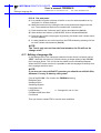
■ How to select job and data files
The method of selecting a job and various data files when loading, saving, verifying, and deleting are described in the following:
✔ Individual Select
Jobs and data files are selected individually one at a time.
✔ Batch Select
Jobs and data files are selected all at one time.
Batch selection can be performed as in the following:
a) Select {EDIT} under the menu in either the floppy disk job list display or the file
select display.
The pull down menu is displayed.
EDIT
DATA
DISPLAY
UTILITY
L
C S
SELECT ALL
R1
CANCEL SELECT
RELATED
NO.:7
TEST0001
TEST0002
TEST0003
TEST0004
TEST0005
TEST0006
TEST0007
!
MOTOMAN ROBOTICS EUROPE
Page: 48
Users’s manual FDDWIN32
Created: 96-01-31 Revised: 99-11-25
Doc. name: Mrs55000-ch3.fm
Switch select mode
b) Select {SELECT ALL}.
All jobs are selected.
DATA
EDIT
DISPLAY
UTILITY
L
C S
FLOPPY DISK/PC CARD
R1
FC2(VERIFY)
RELATED
NO.:7
TEST0001
TEST0002
TEST0003
TEST0004
TEST0005
TEST0006
TEST0007
!
When {EDIT} à {CANCEL SELECT} is selected, the selected item batch
operation is cancelled.
MOTOMAN ROBOTICS EUROPE
User’s manual FDDWIN32
Open a robot job
Created: 96-01-31 Revised: 99-11-25
Page: 49
Doc. name: Mrs55000-ch3.fm
6.10 Open a robot job
Files in the PC can be opened (contents).
Fig.23 Main menu
a) Click on Stop FDD.
b) Mark the wanted file in File information. If where are a lot of files a special
type of files can be selected. Under the menu File type it can be set e.g. [*.jbi]
which results in that only files ending with (jbi) is shown in the window.
c) Then click on the Job-button. A new menu is shown there different sorts of
information can be displayed.
MOTOMAN ROBOTICS EUROPE
Page: 50
Users’s manual FDDWIN32
Created: 96-01-31 Revised: 99-11-25
Open a robot job
Doc. name: Mrs55000-ch3.fm
Fig.24 Job contents
■ View Header
Gives information about title, tool and other main data.
■ View Position
Gives information about the axis position in each joint of the job
Information is given in pulses not millimetre.
(The axis are displayed in the order S,L,U,R,B,T).
■ View Instruction
Display all instructions in the job such as MOVJ, JUMP, ARCON etc.
■ Line Sum
Display the number of lines in the job.
■ Step Sum
Display the number of MOV-instructions in the job.
If the function File is used in the main menu all file information is shown in one
piece.
MOTOMAN ROBOTICS EUROPE
User’s manual FDDWIN32
Editing a language file
Created: 96-01-31 Revised: 99-11-25
Page: 51
Doc. name: Mrs55000-ch3.fm
6.10.A Cut and paste
a) It is possible to make a printout of the file or use it in documentation etc. by
using the Cut & Paste-method.
b) Mark the wanted text by holding the left mouse button and drag across the
text. The marked text shall now be marked with ”inverted text”.
c) Press and hold the Ctrl-button and C-button simultaneous (Ctrl+C).
d) Start another text-editor e.g. MS-WORD, Write or Windows/Notepad.
e) Paste the text in this new program by pressing Ctrl-button and V-button simultaneous (Ctrl+V).
f) It’s also possible to cut out the text from the FDD window by pressing Ctrl-button and X-button simultaneous (Ctrl+X).
NOTE!
The Text is only cut out from the local window, the file will not be
change at all!
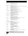
6.11 Editing a language file
In the dialogue box of the Language selection function there is a button named
”EDIT”. Normally this button is not active but by a simple editing of the FC1.INI file it becomes active. This .ini-file can be edited from the Windows Notepad.
When the EDIT-button is active it is possible to edit the language file directly from
the Language selection menu.
NOTE!
If you are not a very skilled PC operator you should not edit this files,
because it is easy to destroy the syntax!
(Part of the FC1.INI - file, found in the FDDWIN-directory)
ReWrite=False
StartDsp=False
StartLang=System
LangSelect=Yes
LangEdit=No
← Change this one to =Yes
FontName=MS Sans Serif
FontSize=8
Then you have to restart FDD to use the new conditions.
MOTOMAN ROBOTICS EUROPE
Users’s manual FDDWIN32
Page: 52
Created: 96-01-31 Revised: 99-11-25
Doc. name: Mrs55000-ch3.fm
Create a new language file
6.12 Create a new language file
When you want to add another language.
Modification can be carried out from the Windows Notepad.
If you want to add other language which is not already available, proceed as follows:
("Korean" as an example)
a) Copy "English.lng" to "User13.lng" (Don't rename it to "Korean.lng".)
b) In the file "User13.lng" you modify row "User13" to "Korean" and to "Local
Language Item". This has to be done in all of the language files.
c) Make "User13.ico" for a country flag if you need. (Created by VisualBasic software.)
d) If you add more, continue with "User14.lng"
Note!
The new languages are not displayed under "System" language. But if you select
"User13", you will see Korean language again.
(Example of the first part of an language file)
FORMAT DESCRIPTION FOR LANGUAGE TRANSLATION
Length IndexNo. "English Name", "Local Language Name", Comment
Start:
30 000 "FDDWIN","FDDWIN",
Title of Main Dialogue Box
30 001 "&File","&Tiedosto",
Menu Command in Main Dialogue Box
30 002 "&Ports Setup","&Sarjaliikenneasetukset",
Menu Command in Main Dialogue Box
30 003 "&FDD Setup","&FDD Asetukset...",
Menu Command in Main Dialogue Box
30 004 "&Exit","&Lopeta",
Menu Command in Main Dialogue Box
30 005 "&Language","&Kieli",
Menu Command in Main Dialogue Box
30 006 "&Help","&Ohje",
Menu Command in Main Dialogue Box
30 007 "&Version","&Versio",
Menu Command in Main Dialogue Box
10 008 "Start FDD","Käynnistä FDD",
Command Button in Main Dialogue Box
10 009 "Directory","Hakemisto",
Command Button in Main Dialogue Box
10 010 "Job","Työ",
Command Button in Main Dialogue Box
10 011 "File","Tiedosto",
Command Button in Main Dialogue Box
10 012 "Exit","Lopeta",
Command Button in Main Dialogue Box
10 013 "Clear","Tyhjennä",
Command Button in Main Dialogue Box
10 014 "Review","Päivitä",
Command Button in Main Dialogue Box
30 015 "File Information","Tiedostoinformaatio",
Frame Box in Main Dialogue Box
30 016 "Communication Status","Tiedonsiirron tila",
Frame Box in Main Dialogue Box
10 017 "Directory","Hakemisto",
Lable in Main Dialogue Box
10 018 "File Type","Tyyppi",
Lable in Main Dialogue Box
20 019 "View Detail","Näytä yksityiskohdat",
Option Button in Main Dialogue Box
20 020 "View Simple","Näytä yksinkertaist.",
Option Button in Main Dialogue Box
10 021 "Quit FDD","Lopeta FDD",
Command Button in Main Dialogue Box
MOTOMAN ROBOTICS EUROPE
User’s manual FDDWIN32
Create a new language file
Created: 96-01-31 Revised: 99-11-25
Page: 53
Doc. name: Mrs55000-ch3.fm
7. Trouble shooting
7.0.A Can not open communication port
■ Port setting not correct / not done!
Correct the setting
■ Hardware key missing!
Check if the hardware key is mounted in right place, if there are several parallel
ports try another one.
Mount a printer cable in the hardware key socket (does not need to be connected
to a printer).
■ Communication disabled
This occurs if you try to start FDD without beeing connected to the robot controller. Close FDD-software, connect to controller restart FDD-software.
Fig.25 Error
message
7.0.B Select Job file.
■ No file was marked!
Mark file and repeat command.
Fig.26 Select file first
7.0.C Remove Shared Component
■ Warning at uninstall sequence
A warning may occure when you are removing a software in the Motoman group.
A file in Windows system is no longer used by any software. Accept to remove
this file by clicking Yes.
Fig.27 Warning message
MOTOMAN ROBOTICS EUROPE
Users’s manual FDDWIN32
Page: 54
Created: 96-01-31 Revised: 99-11-25
Manufacturer
Doc. name: Mrs55000-ch3.fm
8. Windows NT
As the Windows NT do not use Parallel ports such as LPT1. A parallel port must
be set up for the hardware key.
Rainbow Port Driver Microsoft Windows NT.
This version runs only on Intel based machines.
The following files needed to be able to run FDDWIN32 in NT environment.
Necessary files are included in one of the disks.
•
•
•
•
•
RAINPORT.DLL - Rainbow port driver setup.
RAINPORT.HLP - Help file for RAINPORT.DLL.
OEMSETUP.INF - Installation file for Rainbow port driver.
RAINVDD.DLL - Rainbow virtual device driver.
RAINPORT.SYS - Rainbow port driver.
For installation procedure, see Windows NT manual.
More information is found in the file ”sentinel.hlp” included in the diskette.
9. FDD-version
By clicking on Help-button in the main menu the version No. is displayed.
Quit by clicking on Close.
9.1 Manufacturer
Address:
Telephone:
Telefax:
Motoman Robotics Europe AB
P.O. Box 504
SE-385 25 Torsås
Sweden
+46 486 488 00
+46 486 414 10
Notes
Headquarters:
Sweden
MOTOMAN Robotics Europe AB
Box 504, SE-385 25 Torsås, Sweden
Tel: +46-486-48800, +46-486-41410
Group companies:
France
MOTOMAN Robotics SARL
Rue Nungesser et Coli, D2A Nantes-Atlantique, F-44860 Saint-Aignan-de-Grand-Lieu, France
Tel: +33-2-40131919, Fax: +33-40754147
Germany
MOTOMAN Robotec GmbH
Kammerfeldstraße 1, DE-85391 Allershausen, Germany
Tel: +49-8166-90-0, Fax: +49-8166-90-39
Germany
MOTOMAN Robotec GmbH
Im Katzenforst 2, DE-61476 Kronberg/Taunus, Germany
Tel: +49-6173-60-77-30, Fax: +49-6196-60-77-39
Great Britain
MOTOMAN Robotics UK (Ltd)
1 Swan Industrial Estate, Banbury, OXON OX16 8DJ, England
Tel: +44-1295-272755, Fax: +44-1295-267127
Italy
MOTOMAN Robotics Italia SRL
Via Emilia 1420/16, IT-41100 Modena, Italy
Tel: +39-059-280496, Fax: +39-059-280602
Netherlands
MOTOMAN benelux B.V.
Zinkstraat 70, NL-4823 AC Breda, Netherlands
Tel: +31-76-5424278, Fax: +31-76-5429246
Slovenia
RISTRO d.o.o.
Lepovce 23, SI-1310 Ribnica, Slovenia
Tel: +386-61-861113, Fax: +386-61-861227
Spain
MOTOMAN Robotics España S.A.
Avenida Marina 56, Parcela 90, ES-08830 St. Boi de Llobregat (Barcelona), Spain
Tel: +34-93-6303478, Fax: +34-93-6543459
Sweden
MOTOMAN Mecatron Robotic Systems AB
Box 4004, SE-390 04 Kalmar, Sweden
Tel: +46-480-444600, Fax: +46-444699
Distributors:
Czech Republic
MGM Spol s.r.o.
Trebízského 1870, CZ-39002 Tábor, Czech Republic
Tel: +420-361-254571, Fax: +420-361-256038
Denmark
HN-Automatic Robia A/S
Hjulmagervej 4, DK-7100 Vejle, Denmark
Tel: +45-79428000, Fax: +45-79428001
Finland
Robia Suomi OY
Kärsämäentie 8, FI-20300 Turku, Finland
Tel: +358-22145600, Fax: +358-22145660
Greece
Kouvalias Industrial Robots
25, El. Venizelou Ave., GR-17671 Kallithea, Greece
Tel: +30-1-9589243-6, Fax: +30-1-9567289
Norway
Robia ASA
Øvre Eikervei 177, NO-3048 Drammen, Norway
Tel: +47-32217830, Fax: +47-32217840
Portugal
Electro-Arco S.A.
Rua Vice-Almirante Azevedo Coutinho 4, Venda Nova, PT-2700 Amadora, Portugal
Tel: +351-1-4968160, Fax: +351-1-4990696
MOTOMAN ROBOTICS EUROPE AB
a subsidiary of YASKAWA Electric Corporation