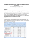
1
HEC-GeoRAS
Walkthrough Workshop
Ryan Meekma, GISP
Gregory Byard, P.E., CFM
©2013 University of Illinois Board of Trustees.
All rights reserved. For permission information,
contact the Illinois State Water Survey.
Welcome
(Who is in the Audience?)
Engineers
• HEC-RAS experts
GIS Professionals
• GIS experts
City Planners
Flood Plain Managers
Engineering + GIS = HEC-GeoRAS
Why Are We Here?
Learn about:
• Data
• GIS
• Engineering
• Geo-RAS
• HEC-RAS
• TROUBLESHOOTING
Geo-RAS Walkthrough
• Not a live DEMO
• Screenshots captured at
each step
Agenda
• Introduction to HEC-GeoRAS and Spatial Data
• Generating Required Data in HEC-GeoRAS
• HEC-GeoRAS to HEC-RAS
• Tools and Tips for modeling & managing spatial data in HEC-RAS
• HEC-RAS to HEC-GeoRAS
• Post Processing in GIS
• Additional HEC-GeoRAS capabilities (as time allows)
Benefits of Using HEC-GeoRAS
• Spatial Relationships
– Link input data, hydraulic modeling, and final floodplain mapping
• Better utilize detailed topographic information
– Make use of LiDAR / survey data
– Increase accuracy and precision in overbank
• Improve modeling efficiency
– Quickly identify impacts of modeling changes and areas of concern
– Utilize GIS staff to aid in model development and mapping
• Visualize results to improve model accuracy
– Easily identify areas of basin interaction
Software Requirements
• HEC-GeoRAS
– HEC-GeoRAS 4.3.93 for use with ArcGIS 9.3
– HEC-GeoRAS 10 for use with ArcGIS 10.0 (today’s discussion)
– HEC-GeoRAS 10.1 for use with ArcGIS 10.1 (just released)
• ArcGIS
– Required Extensions
• Spatial Analyst
• 3D Analyst
• HEC-RAS
– Full functionality of HEC-GeoRAS 4.3.93 requires HEC-RAS 4.0 or later
– RAS Mapper Utility requires HEC-RAS 4.1.0
Identify the Scope of Work
Type \ Level of Analysis
• Regulatory Use
– Detailed Floodplain Study
– Approximate Floodplain Study
• Sediment Transport
• Research and Scientific Analysis
Study Extents
•
•
•
•
Upstream and downstream extents, tributaries, etc.
Available data
Access to survey data
Metadata (digital data is useless without it!)
Metadata, Metadata, Metadata
(We hate it until we need it)
What is Metadata?
• Descriptive
• Data about data
• Content about content
• Data about content
Why do you need Metadata?
• It answers questions about the
integrity / quality of data used in
modeling.
–
–
–
–
–
–
–
–
–
Where did it come from
Who created it
How was it created
When was it created
Why was it created
Who published the data
Was the data ever published
Did data go through a QA/QC process
What is the RMS \ Error
Digital Data Creation - Flowchart
Tips
Figure 3-1 from HEC-GeoRAS
User’s Manual v10
GIS Geo-RAS Walkthrough
Version 10.0
New MXD
Turn on Extensions
Add Data
Digital Data Creation
Projections \ Coordinate Systems
• Units
– Feet
– Meters
File Management
• File location affects processing
time
• File paths are limited to <128
characters with no “wildcard”
characters
Save MXD – Set File Path
Turn on Hec-GeoRAS Toolbar
HEC Geo-RAS Toolbar
Digital Data Creation
Supported topographic data
• DTM
– DEM \ GRID
• Can be tiled to improve processing
– TIN
• May allow for faster processing over large areas
• Should be generated from the LiDAR points
• Survey Points
– Supplement the DTM within the channel
• Manual Elevations
– For lateral structures (with interpolation between points),
ineffective flow areas, blocked obstructions, levees
TIN
DEM
Orthophoto
Create RAS Layers
“make it if you need it” (walk through) or “all at once” (this slide only)
Create Stream Centerline Layer
Layer Name and Filepath
Create XS Cut Lines Layers
Layer Name and Filepath
What Have We Created?
Geo-RAS Data Requirements
Minimum Requirements
Optional Data
• DTM (single or multiple)
•
•
•
•
•
•
•
•
•
•
• Stream Centerline
• Cross Section Cut Lines
Tips
Existing Data can be
loaded / copied to
blank feature classes
Flow Path Centerlines
Main Channel Banks
Land Use (for Manning’s n)
Bridges/Culverts
Inline Structures
Levee Alignments
Ineffective Flow Area
Lateral Structures
Storage Areas
Storage Area Connections
Digital Data Creation
General Editing Rules
• Stream centerlines and flow paths are digitized upstream to
downstream
• Cross sections, inline structures, and bridges/culverts are
digitized from left to right looking downstream
Tips
• Use directional symbology for cross sections and stream centerlines
during digitization
– Layer Properties -> Symbology -> Symbol -> Arrow at End
• Flip reversed cross sections rather that re-digitizing
Developing Stream Centerline
• River stationing is based on the Stream Centerline
– Use the most up to date aerial photography available to check for
development since the most recent orthophotography
– Ensure agreement between the aerial photography and DTM
• Junctions (aka confluences)
– Snapping
• River \ Reach naming
• Downstream reach lengths are based on the Flow Path
Centerlines (Profile Baseline), which may or may not follow
the Stream Centerline for large events
Simple Data Loader
Simple Data Loader
• Start ArcMap Edit session
• Select your “Input data”
• Select your “Target”
– River
• Object Loader Summary
• & Repeat for other Layers
Tule Creek - Tributary
Baxter River – Lower Reach
Baxter River – Upper Reach
Assign River and Reach Names
• Flow Path ID Icon
Line Direction and Label
Developing Cross Section Data
Manual Cross Sections
• Digitized left to right looking
downstream
• Perpendicular to the direction of
flow (cross sections can have bends)
• Must not intersect
• Cross the stream line only once
• Must be contained within DTM
• Can be imported from previously
digitized data
Developing Cross Section Data
Automated Cross Sections
• Specified interval and width
• Perpendicular to stream
centerline
• “This is NOT the preferred
method and should be used
with caution because the lines
are not generated following the
guidelines necessary for
modeling one-dimensional
flow.” - HEC-GeoRAS User’s
Manual v10
Load Cross Sections
(using simple data loader, same process as Stream Centerline)
Line Direction and Label
• NOTE: XS has not been attributed yet
Manually Digitizing Cross Sections
• Begin Edit Session
• Choose Layer to Edit
Manually Digitizing Cross Sections
FLOW DIRECTION
• Click on XSCutlines
• Begin Digitizing
Manually Digitizing Cross Sections
FLOW DIRECTION
• Double Click to End Sketch
• Save Edits
Developing Flow Path Centerlines
(optional … sort of)
• Necessary for downstream reach length extraction
• May specify either:
– Main channel flow path
– Main channel, left overbank, right overbank flow paths
• Main channel flow path may utilize stream
centerline
• Consider the flow path over the range of discharges
to be modeled
Create Flow Path
Flow Path Layer
Select Flowpath & Linetype button
Types of Flowpaths
• Three types of lines
– Centerline
– Left overbank
– Right overbank
Flowpath Usage
• Defines the downstream
reach lengths between
cross-sections in the main
channel and over bank
areas
Developing Channel Bank Data
(optional)
Bank Lines = RED
Bank Points = YELLOW
(Bank points are created where bank lines intersect cross section line)
Finished Creating RAS Layers
• Layer Setup
RAS Layer Setup
Stream Centerline Attributes
• Layer Name = River (feature class name)
• Terrain = Source selected in Layer Setup (TIN)
What Have We Created for the Water Line?
•
•
•
•
•
•
RiverCode
ReachCode
FromNode
ToNode
FromSta (From Station)
ToSta (To Station)
XS Cut Line Attributes
• Only showing Required Layers above
What Have We Created for the XS Layer?
(EVERYTHING! To get started with modeling at least…)
Export RAS Data
• Select Output Folder
• Name File
Exported RAS Data
Two files were created:
• Next step is importing data into a HEC-RAS model
Transitioning from Geo-RAS
to RAS
Gregory Byard, P.E., CFM
[email protected]
(217) 244-0360
Transitioning from Geo-RAS to RAS
Open HEC-RAS
• Start a new project in
HEC-RAS
• From the Geometric
Data Editor, import the
RAS GIS Import File
• Select the appropriate
.sdf file
Import Geometry Data
Select Unit System
• Consider the linear units
of the DTM
• Consider units of data
with which to merge
• Select ‘Next’
Import Geometry Data
River Reach Stream
Lines
• Revise river and
reach names as
necessary
• Select which
stream lines to
import
• Select the merge
mode
• Select ‘Next’
Import Geometry Data
Cross Sections and IB
Nodes
• Choose which cross
sections, bridge/culvert,
inline structure, and
lateral structure to
import
• Select cross section
properties to import
• Assign river stations
• Assign stationing offsets
• Select ‘Next’
Import Geometry Data
Storage Areas and
Connections
• Choose which to
import
• Assign names
• Select volumeelevation or outline
• Select ‘FinishedImport Data’
• Save geometry file
Review Imported Data
Things to review
• Expanse of Manning’s n values
• Location of bank station data
• Add/move/delete ground points (check for gaps, erroneous
data)
• Add/move/delete levees, ineffective flow areas, and blocked
obstructions
• Compare and merge cross section elevation data
• Junction connection and length
Graphical Cross Section Editor
Tip
Throughout HEC-RAS
Hold ‘Ctrl’ to activate measure tool
Hold ‘Shift’ to activate pan tool
Graphical Cross Section Editor
Cross Section Points Filter
Modifying Cross Section Extents
Tip
Very important for proper floodway mapping
Modifying Cross Section Extents
(If you choose ‘Accept edits and leave cut line alone’)
From Import to Running Model
What still needs to be added?
• Data purposefully omitted from
Geo-RAS
• Hydraulic structure data
– Opening geometry, connections
• Additional levee, ineffective
flow, block obstructions data
– Opening geometry, revised
elevations, etc.
• Detailed channel geometry
• Flow data (with boundary
conditions)
Reminder:
“Importing data generated
from GIS layers will not create a
complete river hydraulics model”
Initial Review of Results
Compute the Steady or Unsteady Flow Analysis
• Review the results and adjust your model as necessary
– Check especially for
• Cross sections that cannot contain the range of flows
• Consistent levee overtopping
• Ineffective areas around bridges / natural floodplain constrictions
• Tools for review
– View Cross Sections
– View Profiles
– View 3D Multiple Cross Section Plot
• Set Azimuth Angle to 90
View Cross Sections
View Profiles
View 3D Multiple Cross Section Plot
RAS Mapper
Note: Need DTM in float (.flt) format
To convert a DEM, use “Raster to
Float (Conversion)” tool in ArcMap
RAS Mapper
RAS Mapper
Note: Remove layers and
reload following edits, they
do not update automatically
Processing HEC-RAS Results
Ryan Meekma, GISP
[email protected]
(217) 244-6627
Export GIS Files from HEC-RAS
1.) Open HEC-RAS Model
2.) File\Export GIS Data…
Export GIS Files from HEC-RAS
3.) GIS Export (complete fields)
4.) Turn On HEC-GeoRAS
Toolbar in ArcMap 10
Export GIS Files from HEC-RAS
Extract GIS Data from Hec-RAS using the Geo-RAS Tool in GIS
5.) Importing the RAS GIS
Export file \ SDF Conversion
to XML
6.) Save MXD \ RAS
Mapping \ Layer Setup
Export GIS Files from HEC-RAS
Extract GIS Data from Hec-RAS using the Geo-RAS Tool in GIS
7.) Complete Dialog Box
• Point to RAS GIS Export
File
• Set file path to DTM
• Set Output Directory
Export GIS Files from HEC-RAS
Extract GIS Data from Hec-RAS using the Geo-RAS Tool in GIS
8.) RAS Mapping Toolbar
9.) Watch Magic
Export GIS Files from HEC-RAS
Extract GIS Data from Hec-RAS using the Geo-RAS Tool in GIS
9.) Data Processing Completed
Inundation Mapping Using GeoRAS
• To begin click
– RAS Mapping
– Layer Setup
• Populate post processing
layer menu
Inundation Mapping Using GeoRAS
• Next Step
– RAS Mapping
– Import RAS Data
Inundation Mapping Using GeoRAS
• Bounding Polygon Created
• Defines analysis extent for
inundation mapping
Inundation Mapping Using GeoRAS
• RAS Mapping
– Inundation Mapping
• Water Surface Generation
– Pick a profile
Inundation Mapping Using GeoRAS
• RAS Mapping
– Inundation Mapping
• Floodplain Delineation using
Rasters
– Pick a profile
• DTMGRID – Water Surface
– Positive Numbers
• Water surface is higher than
terrain (flooding)
– Negative Numbers
• Results are dry
Inundation Mapping Using GeoRAS
• WARNING: refinement of
flood inundation results is
not covered in Geo-RAS!
• The ability to judge quality
of terrain and flood
inundation polygons comes
with the knowledge of
study area and experience.
• Smoothing floodplains does
not count as creating
hydraulically correct output.
– It induces error
GIS to RAS, RAS to GIS
GIS Approach to Mapping
Floodplains
Using “3D Analyst” and “Spatial Analyst” Extensions in ArcMap
• Extending Cross sections (Manually editing a copy of layer)
• Creating a TIN from extended Cross Sections
• Convert a TIN to Raster = WSEL Raster
• WSEL – Land Surface = floodplain
• Reclassify raster results
• Convert raster to feature
• Clean up the features
• Create Topology Rules
• Attribute Flood Hazard Lines
Update Elevations
• Incorporate Survey Points into 3D XS feature class
• XS must have previously extracted elevation from the land
surface (DTM or DEM, TIN)
Update Elevations
• Elevation Update Tool
– Requires:
• Point feature class
• Field of elevation values
Update Elevations
• XSCutlines3D feature class
• Elevation Points
• “ElevUpdate” field is added and includes a “1” if point is used
Update Elevations
Developing Bridge \ Culvert Data
(optional) Same method for Inline Structures
RAS Geometry | Bridges / Culverts| River/Reach Names
Stationing
Elevations
Developing Ineffective Flow Areas
(optional)
RAS Geometry | Ineffective Flow Areas | Positions
Developing Blocked Obstructions
(optional)
RAS Geometry | Blocked Obstructions | Positions
Developing Manning’s ‘n’ from
Land Use Data
(optional)
RAS Geometry | Manning’s n Values | Extract n Values
Developing Levee Data
(optional)
RAS Geometry | Levee | Profile Completion
Positions
Developing Lateral Structures
(optional)
RAS Geometry | Lateral Structures| River/Reach Names
Stationing
Elevations
Developing Storage Areas
(optional)
RAS Geometry | Storage Areas |
Elevation Range
Elevation-Volume Data
Developing Tiled Terrain Data
(optional)
• Need a terrain tiles feature class to serve as a look
up table
• Each RAS layer feature must be contained within one
terrain tile polygon feature
• DTMs should overlap to properly represent the
terrain at the edges when using TIN models
• DTMs should break at straight river reaches and not
confluences
• All of Chapter 9 of the GeoRAS Users Manual is
devoted to this topic
Additional Reference Materials
•
•
•
•
http://www.hec.usace.army.mil/
HEC-GeoRAS User’s Manual v10
HEC-GeoRAS 10 Example Data Sets
HEC-RAS 4.1 User’s Manual, Applications Guide, and
Hydraulic Reference Manual
• Tutorial on using HEC-GeoRAS with ArcGIS 10 and HEC
RAS Modeling by Venkatesh Merwade, Purdue University
Ryan Meekma, GISP
[email protected]
(217) 244-6627
Gregory Byard, P.E., CFM
[email protected]
(217) 244-0360