1
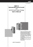
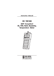
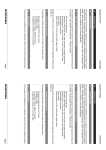
User Manual
EVB90601 Configuration Board
Introduction
The EVB90601 Configuration board is designed to support the MLX90601 based Infrared Thermometer
modules. The hardware board acts as an interface between the USB port of a PC and the module’s SPI
interface. Power for the module and EVB board come from the computer USB port.
OEMs
The EVB90601 is designed to allow OEMs to configure IR sensing for virtually any application quickly.
OEMs can quickly experiment with temperature ranges, optics, etc. to find the best IR configuration to
meet the application needs. Once the best configuration is established, low volume OEMs can easily
configure IR modules for their own use.
For high volume OEMs, Melexis can supply special configured modules, ready to install to customer
specifications. Please contact IR Sales at Melexis for quotations.
Laboratory/R&D
The EVB90601 allows engineers to custom configure the MLX90601 for very high accuracy IR
measurements in an R&D or Laboratory setting.
Getting started
Included in the Kit
USB configuration pcb board
ribbon cable
a USB cable to connect to a PC
small adapter board to easily mount a MLX90601 flex pcb module
samples: MLX90601KZA-CKA and MLX90601KZA-BKA Infrared Modules
software and documentation
Note that it is advised to check for latest software and documentation updates at
www.melexis.com in the section Products: Hardware and Evaluation Boards
390129060101
Rev 005
Page 1
Jan-04
User Manual
EVB90601 Configuration Board
System requirements
Windows 98,Windows NT, Windows2000, Windows XP
Quick Start
1. Install the SW90601 Configuration Software on your computer before connecting the kit to your
USB port.
The latest version will always be available on our website here:
(http://www.melexis.com/prodmain.asp?family=SW90601)
Please check periodically for updates.
2. Install a MLX90601 module into the special connector as shown.
3. Connect the ribbon cable to the large pcb and the small pcb
4. Plug in the USB cable to the Melexis pcb and to your computer
5. When the USB cable is connected, the software will direct you to install the USB drivers (see
the Read First Melexis USB Software Installation Note included with the MLX90601 Configuration
software).
6. Start the MLX90601 Configurator Software on your computer (located in the Program Files).
If everything is correct, you will see the software downloading the data file from the MLX90601.
When you see the software download the EEPROM at startup, the module is communicating correctly
with your computer and this Main Toolbar will show ready:
7. Next the software will show you the following screen. You must input the temperature range that
your module is configured for.
390129060101
Rev 005
Page 2
Jan-04
User Manual
EVB90601 Configuration Board
Factory standard MLX90601BKA and MLX90601CKA modules have:
Tobject range of –20 C to 120 C, Tambient range of –20 C to 85 C. So, you must enter the ranges like
this:
8. Finally, click on “Windows” on the main menu. Then click on “Monitor”. Your computer should
now display the correct To (target temperatures) and Ta (ambient temperatures) as shown here:
(Please note that the Monitor display box can be “enlarged” as any normal MS Windows box by putting
your cursor on the edges of the box.)
Done. Wave the module around and you should see the temperature display change accordingly.
Technical Support:
390129060101
Rev 005
Page 3
Jan-04
User Manual
EVB90601 Configuration Board
If you experience any problems with the module, Configuration board or Software tools please
contact our technical support. When encountering problems with the use of the software, please
mention the “program build” info found at the “about” box in the help menu.
Specialized support can be reached by email at: [email protected]
390129060101
Rev 005
Page 4
Jan-04
User Manual
EVB90601 Configuration Board
Following information is described in next pages:
•
Temperature Ranges, Units Changing
•
Application notes concerning IR-recalibration
•
Reference Blackbodies
•
Calibrate “In-place”
•
Emissivity and Targets
•
Help Files: For your convenience, the Help files implemented in the software are good
documented, and are describing how to use the evaluation board. The most important
help files are presented in next paragraph for easy reference.
•
Application notes concerning FOV (field of view)
•
Troubleshooting
•
PCB Hardware and Firmware Manual
390129060101
Rev 005
Page 5
Jan-04
User Manual
EVB90601 Configuration Board
TEMPERATURE RANGES, UNITS CHANGING:
The temperature ranges that the IR modules are set for, must always be entered manually into the PC
software. There is no way at this time for the PC software to know what the configured temperature
ranges are inside the module.
This, along with temperature units can be changed manually like this:
Click on “Configuration”, then “Preferences”, then “Miscellaneous”. Then select
“Temperature Units” as shown here:
Select deg F or K (deg C is default).
Click on “Configuration”, then “Settings” on the main menu. Here you have to have to enter the calibrated
range of the module you are using.
The screen is shown here:
(You must always make sure you have set the correct “Settings” for the temperature ranges. There is no
means for temperature range information to be stored in the MLX90601 module EEPROM. This
temperature range information must be inserted manually, external to the module. This means if you
change any modules, you must record the temperature ranges that you have set the module to.)
RE-CALIBRATION USING THE EVB90601
390129060101
Rev 005
Page 6
Jan-04
User Manual
EVB90601 Configuration Board
Always save the original EEPROM settings of a module before making any EEPROM changes. To do
this, click on the main menu “File”. Then click “Save as”. Give the file a name and save it on your
computer.
This will allow you to always return the module to its original settings, calibration, and accuracy.
(There is also an internal ID number in EEPROM that cannot be changed. The module serial number is
always displayed in the blue bar of the main menu screen when you are connected.)
Up to 7 IR calibration points are available when re-calibrating. However, for many applications only
one IR calibration point is needed as the EVB software follows established IR curves for high emissivity
objects quite accurately.
Situations where multiple calibration points can be used to increase accuracy are:
To generate the highest level of accuracy for wide temperature ranges. Example: to have the highest
accuracy from To = 0 to 500 C you can use up to 7 points.
When emissivity is less than 0.9, or unknown, or varies with temperature, using more calibration points
can allow you to correct for the variations.
Adding an unusual optical system: lenses, narrow bandpass transmissions, etc. can alter the curve
algorithm used in the software. In this situation, using more calibration points will adapt the curve to the
application.
In general, using more calibration points can allow you to calibrate out errors that can come from a variety
of sources in your intended application.
If you get poor results from your first attempts at re-calibration:
Reload the original EEPROM settings from your test module that you saved on disk back into the module.
Then start the re-calibration tests again.
Always reload the original EEPROM when you wish to re-calibrate the same module.
Additional re-calibration instructions can be found in the “Help” files in the software. Also, the “Help” files
are printed in this manual for your reference.
REFERENCE “BLACKBODY”
To perform a calibration, you can use a reference surface temperature “blackbody”.
There are numerous commercial blackbodies available. Choose a unit that suits your temperature range
and accuracy.
“TEMPERATURE BATH” as a “Blackbody” A standard laboratory temperature bath is a near “ideal
blackbody”. The emissivity of water, and nearly all liquids, is around 0.985. That is as good as many of
the highest quality commercial blackbodies. Here are some simple rules in using a temperature bath for a
blackbody:
1. It must be a “stirred” temperature bath so that the top layer is constantly being controlled
correctly.
2. If you wish to measure above approx. 40 C, you should remove the water in the bath and replace
it with a non-evaporating fluid. (Reason for this is that evaporating water will condense on the IR
module sensor window. Condensation on the IR sensor window distorts it’s ability to see heat.) A
good working fluid could be automotive antifreeze or equivalent. Such fluids are excellent as they
390129060101
Rev 005
Page 7
Jan-04
User Manual
EVB90601 Configuration Board
have high evaporation points, and low freezing points. Using such a fluid, you can have a very
high accuracy blackbody from –40 C to 100 C.
3. For temperatures below 10 C, a temperature bath with such a fluid is better than conventional
blackbodies. On conventional blackbodies, low temperatures can cause condensation on the
face of the blackbody. This will distort its readings. A temperature bath with low working temp
fluid has no such problem because it is “stirred”, and the stirring motion prevents water forming a
condensing layer on top.
CALIBRATE “IN PLACE”
The most accurate IR calibration for OEMs is to calibrate the module on the actual target that you wish to
measure, under the conditions that you wish to measure it.
Example: to achieve the highest accuracy with a fusing roll in a copier, set up a calibration station using
an actual fusing roll and heater with a reference temperature sensor actually mounted on the fuser roll.
Bring the fuser roll to the temperature(s) you want highest accuracy, and then perform the calibration(s) to
match the known surface temperature(s) desired. Then the IR module can be installed on a production
unit.
EMISSIVITY and TARGETS
Non-metals normally have a very high emissivity, greater than 0.9, and can be measured very well using
IR.
Metals (uncoated metals) are normally not good targets for IR temperature measurements as they are
normally very low emissivity (less than 0.2). This means that more than 80% (1.0 – 0.2 = 0.80) of the
signal the IR sensor will see is ambient reflection. If the ambient reflection changes by even small
amounts, errors will be introduced. Metals should be coated with a non-metal for best measurements.
The only exception is this: Uncoated metals can be measured with reasonable accuracy at high
temperatures (normally above 500 C). The reason for this is that changes in ambient reflections are small
IR signals compared to the amount of IR radiation coming from a hot metal. In other words, the IR signal
is dominated by the metal even when emissivity is low if the temperature is high enough.
Biological materials are very good targets with emissivities better than 0.98, nearly blackbody (no
reflection).
Plastics, nearly all plastics are very good targets for IR. The only exceptions are thin polypropylene and
thin polyethylene, which allow IR to pass right through, depending on the thickness. Most plastic IR
lenses are made of those material precisely because of those properties.
There are numerous Emissivity Tables available on the internet for general reference.
Help Files
For your convenience, the Help files in the software are presented for easy reference.
390129060101
Rev 005
Page 8
Jan-04
User Manual
EVB90601 Configuration Board
390129060101
Rev 005
Page 9
Jan-04
User Manual
EVB90601 Configuration Board
390129060101
Rev 005
Page 10
Jan-04
User Manual
EVB90601 Configuration Board
390129060101
Rev 005
Page 11
Jan-04
User Manual
EVB90601 Configuration Board
390129060101
Rev 005
Page 12
Jan-04
User Manual
EVB90601 Configuration Board
390129060101
Rev 005
Page 13
Jan-04
User Manual
EVB90601 Configuration Board
390129060101
Rev 005
Page 14
Jan-04
User Manual
EVB90601 Configuration Board
390129060101
Rev 005
Page 15
Jan-04
User Manual
EVB90601 Configuration Board
390129060101
Rev 005
Page 16
Jan-04
User Manual
EVB90601 Configuration Board
390129060101
Rev 005
Page 17
Jan-04
User Manual
EVB90601 Configuration Board
390129060101
Rev 005
Page 18
Jan-04
User Manual
EVB90601 Configuration Board
390129060101
Rev 005
Page 19
Jan-04
User Manual
EVB90601 Configuration Board
390129060101
Rev 005
Page 20
Jan-04
User Manual
EVB90601 Configuration Board
390129060101
Rev 005
Page 21
Jan-04
User Manual
EVB90601 Configuration Board
390129060101
Rev 005
Page 22
Jan-04
User Manual
EVB90601 Configuration Board
390129060101
Rev 005
Page 23
Jan-04
User Manual
EVB90601 Configuration Board
390129060101
Rev 005
Page 24
Jan-04
User Manual
EVB90601 Configuration Board
390129060101
Rev 005
Page 25
Jan-04
User Manual
EVB90601 Configuration Board
390129060101
Rev 005
Page 26
Jan-04
User Manual
EVB90601 Configuration Board
390129060101
Rev 005
Page 27
Jan-04
User Manual
EVB90601 Configuration Board
390129060101
Rev 005
Page 28
Jan-04
User Manual
EVB90601 Configuration Board
390129060101
Rev 005
Page 29
Jan-04
User Manual
EVB90601 Configuration Board
390129060101
Rev 005
Page 30
Jan-04
User Manual
EVB90601 Configuration Board
390129060101
Rev 005
Page 31
Jan-04
User Manual
EVB90601 Configuration Board
Changing the “FIELD OF VIEW” OF THE MLX90601
Standard FOV (field of view)
The standard FOV (field of view) of the MLX90601 IR module is as shown here:
FOV MLX90601 w ith Standard 2.5 mm Aperture TO
Can
100
% Energy Seen by IR Detector
90
80
70
60
50
40
30
20
10
0
-60
-50
-40
-30
-20
-10
0
10
20
30
40
50
60
Angle in De gre e s
What this means is that if you want the highest possible accuracy, you need to make sure your target fills
the +/-50 deg angle seen by the sensor.
Minimum Resolution (approx.): 0.025 deg C at 25 C target temperature
(Minimum Resolution is achieved with the “low pass filter” inside the MLX90601 processor set at
maximum filtering. This is the standard factory setting. This results in approximately 600 ms response
time. The resolution can be further improved by additional filtering by an external processor if the
MLX90601 is connected by SPI bus to a low cost micro-controller. Of course, the response time
increases when this technique is used. The filter setting is accessible by using the EVB90601 kit.)
390129060101
Rev 005
Page 32
Jan-04
User Manual
EVB90601 Configuration Board
CHANGING THE FOV OF THE MLX90601 USING SIMPLE APERTURES
(Note: The Melexis part # EVB90601 is necessary when adding an aperture to a standard MLX90601.
Normally, a one point IR re-calibration must be performed to adapt the aperture.)
The digital signal processing of the MLX90601 allows for easy modifications to customize the module for
many applications at minimal engineering and manufacturing cost.
•
•
•
•
•
•
•
The aperture must be mounted directly onto the thermopile sensor of the MLX90601, and epoxied
into place.
They must be thermally connected, with the assembly staying isothermal under your desired
operating conditions.
The aperture must be a high thermal conductance metal.
The internal aperture must be blackened, or coated to eliminate internal reflections.
The internal aperture can be threaded to further eliminate reflections.
Black anodized aluminum with internal sharp threads makes a very good aperture assembly.
Reducing the FOV of the sensor reduces the base level temperature resolution of the module.
(When an aperture is added, the amount of energy seen by the detector is reduced. As a result,
the basic voltage output of the detector is reduced. )
Example 1: Adding 3.5 mm x 4 mm Aperture
The following shows the optical effect of adding an aperture device with a 3.5 mm diameter hole, by 4 mm
length above the top of the sensor.
FOV with 3.5 mm dia x 4 mm length Aperture
100
90
% Energy Seen by IR Detector
80
70
60
50
40
30
20
10
0
-25
-20
-15
-10
-5
0
5
10
15
20
25
Angle in Degrees
As you can see, this simple aperture has reduced the FOV quite considerably.
Minimum Resolution (approx.): 0.04 deg C at 25 C target temperature
390129060101
Rev 005
Page 33
Jan-04
User Manual
EVB90601 Configuration Board
Example 2: Adding 3.5 mm x 8 mm Aperture
FOV with 3.5 mm dia x 8 mm length Aperture
100
90
% Energy Seen by IR Detector
80
70
60
50
40
30
20
10
0
-15
-10
-5
0
5
10
15
Angle in Degrees
Minimum Resolution (approx.): 0.13 deg C at 25 C target temperature
Example 3: Adding 3.5 mm x 10 mm Aperture
FOV with 3.5 mm dia x 10 mm length Aperture
100
90
% Energy Seen by IR Detector
80
70
60
50
40
30
20
10
0
-15
-10
-5
0
5
10
15
Angle in Degrees
Minimum Resolution (approx.): 0.18 deg C at 25 C target temperature
390129060101
Rev 005
Page 34
Jan-04
User Manual
EVB90601 Configuration Board
Additional Suggestions:
For high volume OEMs (minimum 50K/year units), Melexis can supply the MLX90601 with OEM specified
apertures or optical systems installed and calibrated. Please contact Melexis for a quotation.
390129060101
Rev 005
Page 35
Jan-04
User Manual
EVB90601 Configuration Board
For lower volume OEMs, Melexis can provide assistance for customer installation and configuration of
optical assemblies.
Notes:
1. Please note that the “Minimum Resolution” of the MLX90601 is affected as the FOV is made
narrow by apertures. This is due to the reduced amount of energy entering the detector with the
limits of the amplifiers inside the MLX90313 chip. The resolution can be improved for narrow
FOVs by adding “focusing” optical assemblies. Please contact Melexis for OEM design
assistance on this topic. Focusing optics should be used only when aperture optics are truly
inadequate for a desired application. Focusing optics add complexity, and additional engineering
and parts costs.
2. For high temperature applications, the FOV can be made very narrow using only apertures. High
temperature targets emit substantial IR energy. The relative high amount of IR energy supplies
plenty of energy to drive the thermopile detector. For example, just using apertures to make a
FOV of 2.9 degrees full angle, on a 500 C target can deliver approx. 0.5 deg C resolution with the
MLX90601. An FOV of 2.9 degrees full angle is a 20:1 Distance to Spot size ratio (distance of 1
meter, spot size of 5 cm). That is a fairly sharp FOV. Please contact Melexis for further OEM
design assistance, if necessary.
3. Aperture, and thus FOV, spot geometry does not have to be “round”. The target spot area can be
made square, rectangular, wide, thin, etc. Much of this can be done with simple apertures to
achieve design goals. Please contact Melexis for assistance in this area.
4. The engineering trick, in adding any optical assembly, is to make sure that the entire optical
assembly remains isothermal (one temperature, no gradients from front to back) in the application
that is intended. In applications where the ambient can change quickly, or an operator can touch
the assembly, it is best to insulate the metal heat sink sufficiently to overcome any normal
potential thermal upsets. Please contact Melexis IR Sales for assistance if needed.
390129060101
Rev 005
Page 36
Jan-04
User Manual
EVB90601 Configuration Board
Appendix A: Troubleshooting guide
Problem
Possible solutions
The software won’t install from
the internet.
The file can get corrupted during download from the internet. Try saving the install file to
your local hard drive before opening it. Use the option ‘save file to disk’ when clicking the file
using a browser.
The software does not complete
installation when upgrading or
reinstalling the software.
Always delete a prior version of the software before installing the newest version.
Manually delete the program folder where a previous installation is located. By default this
will be in C:\Program Files\Melexis\90313 Configurator\. Then try again installing the new
software.
Call the Technical support.
The Monitor window gives
random results.
The module is not connected properly to the Configuration Board. Connect the module.
By accident, I have overwritten
the module eeprom. Can I
restore the original contents ?
No, unless you have made a backup copy of your original EEPROM data.
Check the flat cable between the module and the board.
If you don’t have a copy, you should contact the technical support.
Appendix B: Hardware and Firmware Manual
Hardware User’s Manual
Table of Contents:
Overview................................................................................................................................................................... 38
Connectors ................................................................................................................................................................ 39
Jumpers Settings ....................................................................................................................................................... 39
Principle of Operation............................................................................................................................................... 39
User interface ............................................................................................................................................................ 40
Commands List ......................................................................................................................................................... 41
Error messages .......................................................................................................................................................... 49
Appendix A – MLX90601 USB Evaluation Board Commands List ...................................................................... 50
Appendix B – FTDI Chip Drivers for Virtual COM Port........................................................................................ 50
Appendix C – Installation of the VCP drivers under Windows XP ........................................................................ 51
Revision 1.0
05-NOV-2003
390129060101
Rev 005
Page 37
Jan-04
User Manual
EVB90601 Configuration Board
Overview
The MLX90601 USB evaluation board (EVB) provides virtual serial communication interface
between a PC and a single MLX90601 module. Physically, the EVB is connected to the PC’s
USB connector and uses the PC’s built-in USB interface. The PC application software can access
the MLX90601 module as a virtual RS-232 serial device by using of the Virtual COM Port
Drivers for the respective operating system (see the Appendix B).
This EVB does not require any external power supply because it is entirely supplied by the USB
bus. The board itself provides the necessary power supply to the attached MLX90601 module.
The block diagram of the MLX90601 USB evaluation board is provided below:
Jumper
JP1
Reset
Button
Module’s
Test Points
USB
protocol
EEPROM
PIC Micro
Controller
Switch for
5V Supply
USB to
RS-232
converter
SPI Interface
USB B
Connector
Module’s
10 pins
Connector
Power Supply
The external view of the EVB is the following:
Module’s Outputs Test Points
ICSP
Contact
Pads
USB B
Connector
Module’s
10 pins
Connector
390129060101 +5V Applied to the
Module LED
Rev 005
ECHO Page 38Reset
Jumper
Button
Receive/Transmit
via USB LED
Jan-04
User Manual
EVB90601 Configuration Board
Connectors
The MLX90601 is connected to the EVB’s 10-pin IDC connector (CN2):
REL
+5V
DOUT
CLK
REF
1
3
5
7
9
2
4
6
8
10
GND
DIN
CS
IR
TA
CN2
IDC CONNECTOR, 2mm pitch
The DIN, DOUT, CLK and CS signals form the communication SPI interface of the module’s
ASIC. These signals can be used for reading from and writing to the ASIC’s internal registers
and its built-in configuration EEPROM.
The IR, TA, REL and REF signals are the module’s output signals which can have different
meaning depending on the actual configuration. These signals could be easily accessed on the
EVB, at the respective test points (KT1÷KT5).
The +5V is the module’s supply voltage, which is not permanently applied to the module. The
supply ON and OFF states are controlled by the software and are indicated by the LED D4.
The connector CN1 is an optional In-Circuit Serial Programming (ICSP) connector for
(re)programming of the microcontroller’s firmware. The connector does not exist as a physical
component. However, the pinout of the contact pads is the following:
VPP
CLOCK
DATA
STOP
VSS
1
2
3
4
5
6
CN1
CONTACT PADS
During the optional in-circuit serial (re)programming the STOP signal must be connected to the
VSS signal.
The USB B Connector (CN3) is with a standard pinout, so it is compatible with the generalpurpose USB A to USB B computer cables that can be found in any PC store.
Jumpers Settings
The jumper JP1 (ECHO) determines the ECHO mode – NO ECHO (open) or ECHO (closed).
Principle of Operation
The MLX90601 evaluation board acts as an interface between a MLX90601 module and the PC.
It allows performing of all basic read/write operation with the module’s internal registers or
EEPROM. It also provides several test points with the important module’s output signals.
390129060101
Rev 005
Page 39
Jan-04
User Manual
EVB90601 Configuration Board
The microcontroller (U1) PIC18F252 (Microchip) is used to convert the PC application software
commands to the module’s SPI commands and to return the module’s replies back to the PC
software. The microcontroller uses its built-in UART port for communication with the PC.
The USB to UART conversion is accomplished by the FT232BM (FTDI Chip) IC (U2). From the
PC application software point of view the USB to UART converter IC remain invisible; the EVB
is accessed as a standard RS-232 device, while the physical media is the USB interface.
The corresponding Virtual COM Port Drivers provided by FTDI Chip (available for most of the
existing operating systems) must be previously installed (see the Appendix B).
The data written in the external EEPROM 93C46 (U3) is used to customize the USB VID, PID,
Serial Number, Product Description String and Power Descriptor value of the FT232BM. This
data during the USB link establishment and it is not used by the EVB’s microcontroller.
The LED D2 indicates the data transfer (receive and transmit) via USB.
User interface
Initially, the symbols sent to the EVB via the virtual RS-232 are echoed if the jumper JP1
(‘ECHO’) is shorted and NOT echoed if the jumper JP1 is open. Further, during the normal
operation the echoing could be enabled or disabled by the software.
The ECHO mode is convenient for manual operations, when a standard terminal emulation
program is used to type different commands to the evaluation board. If the EVB is to be used
with dedicated PC application software to configure, calibrate or recalibrate the module, then the
NO ECHO mode could be preferred.
The settings of the PC virtual serial RS-232 port must be the following:
Baud rate: 115200
Data bits: 8
Parity: None
Stop bit: 1
Flow control: None
All the commands supplied from the PC to the EVB are text (ASCII) statements ending with a
carriage return symbol (CR). The syntax is the following (1 command and up to 4 arguments):
command [argument1] [argument2] [argument3] [argument4] <CR>
390129060101
Rev 005
Page 40
Jan-04
User Manual
EVB90601 Configuration Board
The commands are 2-character alphanumeric strings. The arguments are 1-byte (0-255),
alphanumeric strings in HEX radix. Additional special symbols such as space intervals, commas,
dots, etc. can be placed between the command and arguments in order to make the statements
more readable and understandable. The only restriction is one statement to be not longer than 30
bytes (characters). The commands and arguments are 2 characters long. The leading zeros of
arguments are also required. For example the argument ‘0x0B’, should be written as ‘0B’. If the
zero is missed and it is entered as ‘B’, the firmware will accept it as ‘B0’. All missing arguments
are accepted as ‘00’. For example the command ‘rd 00 00’ can be shorten to ‘rd’. But the
command ‘wr 00 0A 0B’ CANNOT be entered as ‘wr 0A 0B’, because, in this case, it will be
recognized as ‘wr 0A 0B 00’.
If the arguments passed to some command are not sufficient (for example the command needs 3
arguments, but only 2 are supplied), 0x00 replaces the missing arguments. If the arguments
passed to some command are more than required, only the necessary arguments are considered.
The rest of them are just skipped.
The interface is NOT case sensitive! The entered commands and arguments could be either lower
or upper case.
If the commands are typed manually (using any standard terminal emulation program) and a
typing mistake is encountered, the entire command statement can be removed by pressing the
ESC button. The last typed symbols could be removed also by pressing the BACKSPACE
button.
The commands are passed for processing after sending of the <CR> symbol (ENTER button).
All the returned values by the EVB are also in text format (ASCII symbols) and can be read by
any standard terminal emulation program. The numbers returned are in HEX radix.
Commands List
The EVB recognizes the following commands:
1. Reading the micro-controller registers. This also includes the special purpose registers and
micro-controller ports. The microcontroller PIC18F252 uses 12 bits to address its data memory
and special function registers
Syntax:
rd
address MS byte
address LS byte
command
argument 1, HEX byte
argument 2, HEX byte
argument 3, HEX byte
argument 4, HEX byte
Return Value:
One HEX byte (2 chars) with the contents of the specified register<CR>.
Example:
390129060101
Rev 005
Page 41
Jan-04
User Manual
EVB90601 Configuration Board
rd 0FF5
2. Writing to the micro-controller registers. This also includes the special purpose registers and
micro-controller ports. The microcontroller PIC18F252 uses 12 bits to address its data memory
and special function registers
Syntax:
wr
address MS byte
address LS byte
value
command
argument 1, HEX byte
argument 2, HEX byte
argument 3, HEX byte
argument 4, HEX byte
Return Value:
None.
Example:
wr 0FF5 14
3. PCB identification. The ID number of MLX90601 USB Evaluation Board is 0x0C. But to keep
the compatibility with any older application software, when the id command is issued without
arguments (i.e. all of them are 0x00) the MLX90601 USB EVB will return an ID 0x07 as the
previous version EVB. When a non-zero first argument is sent, then the EVB will reply with
0x0C.
Syntax:
id
extended
command
argument 1, HEX byte
argument 2, HEX byte
argument 3, HEX byte
argument 4, HEX byte
Return Value:
in compatible mode:
07 <CR> (default, when extended is equal to 0x00)
or
0c <CR> (if the extended is different than 0x00)
Example:
id
or
id 01
4. Software reset. This command resets entirely the EVB’s microcontoller, and re-initializes its
memory and registers. It is equal to the hardware reset, performed by the reset button.
390129060101
Rev 005
Page 42
Jan-04
User Manual
EVB90601 Configuration Board
Syntax:
rs
command
argument 1, HEX byte
argument 2, HEX byte
argument 3, HEX byte
argument 4, HEX byte
Return Value:
None.
Example:
rs
5. Welcome message. Returns a text description of the PCB function, firmware version and
release date.
Syntax:
wl
command
argument 1, HEX byte
argument 2, HEX byte
argument 3, HEX byte
argument 4, HEX byte
Return Value:
<CR>
90601 MLX Evaluation Board USB <CR>
Version 1.07, 21-OCT-2003<CR>
Melexis BG<CR>
Example:
wl
6. Modules’ supply voltage. Depending on the ‘source’ value, this command switches the power
supply ON or OFF:
•
•
Source = 0x01 or Source = 0x02 – Connects +5V supply to the module
Source ≠ 0x01 and Source ≠ 0x02 – Disconnects the supply from the module.
Syntax:
sv
source
command
argument 1, HEX byte
argument 2, HEX byte
argument 3, HEX byte
argument 4, HEX byte
Return Value:
None.
390129060101
Rev 005
Page 43
Jan-04
User Manual
EVB90601 Configuration Board
Example:
sv 01
7. Reading the contents of module’s ASIC EEPROM. The supplied address is 8 bits. The result is
16 bits.
Syntax:
m1
address
command
argument 1, HEX byte
argument 2, HEX byte
argument 3, HEX byte
argument 4, HEX byte
argument 2, HEX byte
argument 3, HEX byte
argument 4, HEX byte
or
re
address
command
argument 1, HEX byte
Return Value:
Two HEX bytes (4 chars) with the contents of the specified EEPROM address<CR>.
Example:
m1 00
8. Reading the contents of module’s ASIC internal registers. The supplied address is 8 bits. The
result is 16 bits.
Syntax:
m2
address
command
argument 1, HEX byte
rr
address
command
argument 1, HEX byte
argument 2, HEX byte
argument 3, HEX byte
argument 4, HEX byte
argument 2, HEX byte
argument 3, HEX byte
argument 4, HEX byte
or
Return Value:
Two HEX bytes (4chars) with the contents of the specified internal register address<CR>.
Example:
m2 00
9. Writing to the module’s ASIC internal registers at the specified address. The supplied address
is 8 bits. The data is 16 bits.
Syntax:
390129060101
Rev 005
Page 44
Jan-04
User Manual
EVB90601 Configuration Board
m3
address
data MS byte
data LS byte
command
argument 1, HEX byte
argument 2, HEX byte
argument 3, HEX byte
rw
address
data MS byte
data LS byte
command
argument 1, HEX byte
argument 2, HEX byte
argument 3, HEX byte
argument 4, HEX byte
or
argument 4, HEX byte
Return Value:
None.
Example:
m3 10 B2 00
10. Writing to the module’s ASIC EEPROM at the specified address. The supplied address is 8
bits. The data is 16 bits.
Note! The ASIC’s EEPROM is normally locked. To unlock it, two additional commands should
be issued, after applying the power supply and before attempting to write into the EEPROM:
1.) m3 10 B2 00 – to enter the test mode
2.) m3 18 00 65 – to remove the EEPROM write protect.
Note! The ASIC’s EEPROM should be erased before writing. To do this, one of the following
commands should be performed after unlocking the EEPROM and before the writing process:
•
•
m6 address – to erase the EEPROM at the specified address, or
m7 – to erase the entire EEPROM.
Syntax:
m4
address
data MS byte
data LS byte
command
argument 1, HEX byte
argument 2, HEX byte
argument 3, HEX byte
we
address
data MS byte
data LS byte
command
argument 1, HEX byte
argument 2, HEX byte
argument 3, HEX byte
argument 4, HEX byte
or
argument 4, HEX byte
Return Value:
None.
Example:
m4 00 02 C3
390129060101
Rev 005
Page 45
Jan-04
User Manual
EVB90601 Configuration Board
11. Block writing to the ASIC’s EEPROM. The address is not required because this command
fills the entire EEPROM with the provided data (16 bits).
Note! The ASIC’s EEPROM is normally locked. To unlock it, two additional commands should
be performed, after applying the power supply and before attempting to write into the EEPROM:
1.) m3 10 B2 00 – to enter the test mode
2.) m3 18 00 65 – to remove the EEPROM write protect.
Note! The ASIC’s EEPROM should be erased before writing. To do this, one of the following
commands should be performed after unlocking the EEPROM and before the writing process:
•
•
m6 address – to erase the EEPROM at the specified address (this command should be
cycled over the all addresses), or
m7 – to erase the entire EEPROM.
Syntax:
m5
command
data MS byte data LS byte
argument 1, HEX byte
argument 2, HEX byte
argument 3, HEX byte
argument 4, HEX byte
argument 3, HEX byte
argument 4, HEX byte
or
bw
command
data MS byte data LS byte
argument 1, HEX byte
argument 2, HEX byte
Return Value:
None.
Example:
m5 02 C3
12. Erasing to the ASIC’s EEPROM at the specified address. The supplied address is 8 bits. No
data is required.
Note! The ASIC’s EEPROM is normally locked. To unlock it, two additional commands should
be performed, after applying the power supply and before attempting to write into the EEPROM:
1.) m3 10 B2 00 – to enter the test mode
2.) m3 18 00 65 – to remove the EEPROM write protect.
Syntax:
m6
390129060101
Rev 005
address
Page 46
Jan-04
User Manual
EVB90601 Configuration Board
command
argument 1, HEX byte
ee
address
command
argument 1, HEX byte
argument 2, HEX byte
argument 3, HEX byte
argument 4, HEX byte
argument 2, HEX byte
argument 3, HEX byte
argument 4, HEX byte
or
Return Value:
None.
Example:
m6 00
13. Block erasing to the ASIC’s EEPROM. The address and data are not required because this
command erases the entire ASIC’s EEPROM.
Note! The ASIC’s EEPROM is normally locked. To unlock it, two additional commands should
be performed, after applying the power supply and before attempting to write into the EEPROM:
1.) m3 10 B2 00 – to enter the test mode
2.) m3 18 00 65 – to remove the EEPROM write protect.
Syntax:
m7
command
argument 1, HEX byte
argument 2, HEX byte
argument 3, HEX byte
argument 4, HEX byte
argument 1, HEX byte
argument 2, HEX byte
argument 3, HEX byte
argument 4, HEX byte
or
be
command
Return Value:
None.
Example:
m7
14. Reading the contents of microcontroller’s EEPROM address. The supplied address is 8 bits.
The result is 8 bits.
Syntax:
er
address
command
argument 1, HEX byte
argument 2, HEX byte
argument 3, HEX byte
argument 4, HEX byte
Return Value:
One HEX byte (2 chars) with the contents of the specified EEPROM address<CR>.
390129060101
Rev 005
Page 47
Jan-04
User Manual
EVB90601 Configuration Board
Example:
er 02
15. Writing to the microcontroller’s EEPROM at the specified address. The supplied address is 8
bits. The data is 8 bits.
Syntax:
ew
address
data
command
argument 1, HEX byte
argument 2, HEX byte
argument 3, HEX byte
argument 4, HEX byte
Return Value:
None.
Example:
ew 02 C3
Note! The microcontoller’s EEPROM address 0xFF is reserved! Changing the EEPROM value
written to this address may cause the EVB to stop responding!
16. Wait Time. The EVB provides a 150 bytes input circular buffer. One or more commands may
be sent to the PCB without any pausing between them. They will be processed consecutively and
the respective return values will be sent out (if the respective commands return any results). If the
execution of the sent commands should be separated in time, the respective wait time interval
may be introduced in the commands sequence (up to 255ms).
This command does nothing else but wait the specified amount of time (in milliseconds).
Syntax:
wt
waittime
command
argument 1, HEX byte
argument 2, HEX byte
argument 3, HEX byte
argument 4, HEX byte
Return Value:
None.
Example:
wt 0A
17. Echo. At startup the echo mode depends on the presence of the jumper JP1. However the
echo mode could also be changed by the software. If the echo argument is zero then the echo is
turned OFF, if the echo argument is not zero – the echo is turned ON.
390129060101
Rev 005
Page 48
Jan-04
User Manual
EVB90601 Configuration Board
Syntax:
ec
echo
command
argument 1, HEX byte
argument 2, HEX byte
argument 3, HEX byte
argument 4, HEX byte
Return Value:
None.
Example:
ec 01
Error messages
The MLX90601 USB EVB may generate the following error messages:
!c1
!c2
!c3
390129060101
Rev 005
The supplied command is not valid.
NON-HEX symbols provided as arguments
Input queue full – in this case the last sent command is lost.
Page 49
Jan-04
User Manual
EVB90601 Configuration Board
Appendix A – MLX90601 USB Evaluation Board Commands List
argument1
Command
rd
wr
argument2
address MS address LS
byte
byte
address MS address LS
byte
byte
id
rs
wl
sv
re, m1
rr, m2
rw, m3
we, m4
bw, m5
ee, m6
be, m7
er
ew
wt
ec
source
address
address
address
address
data MS
address
address
address
waittime
echo
data MS
data MS
data LS
Brief Description
argument3
Read the PIC memory/registers
value
data LS
data LS
data
Write to PIC memory/registers
PCB Identification
Software reset
Welcome message
Switch ON /OFF the module’s supply voltage
Read the module’s EEPROM
Read the module’s internal registers
Write to module’s internal registers
Write to module’s EEPROM
Block write to module’s EEPROM
Erase module’s EEPROM
Block erase module’s EEPROM
Read the microcontroller’s user EEPROM
Write to microcontroller’s user EEPROM
Introduce wait time
Enable / disable ECHO
Appendix B – FTDI Chip Drivers for Virtual COM Port
The MLX90601 USB Evaluation Board requires the installation of the Virtual COM Port (VCP) Drivers for the
FT232BM USR to UART converter. Please download the latest version for your operating system from the
following addresses:
The FTDI Chip Drivers page is:
http://www.ftdichip.com/FTDriver.htm
The VCP Drivers for Windows 98 / ME / 2000 / XP (with enhanced BM series support):
http://www.ftdichip.com/FTWinDriver.htm (select the Enhanced BM series support)
390129060101
Rev 005
Page 50
Jan-04
User Manual
EVB90601 Configuration Board
Appendix C – Installation of the VCP drivers under Windows XP
1.
2.
3.
4.
Unzip the downloaded VCP drivers if you have saved them as a .ZIP file.
Plug the MLX90601 USB Evaluation Board to one of the PC USB connectors. The pop-up message “Found
new hardware MLX90601 Evaluation Board” should appear.
After that the Found New Hardware Wizard will automatically display, proposing to install the software for
MLX90601 Evaluation Board:
Select “Install from a list of specific location (Advanced)” and press “Next”.
Select “Search for the best driver in these locations” and check only the box “Include the location in the
search”. Point the directory where you have downloaded and unzipped the FTDI drivers. Press “Next”
button to continue.
If the following window appears, choose “Continue Anyway”.
390129060101
Rev 005
Page 51
Jan-04
User Manual
EVB90601 Configuration Board
5.
Press “Finish” to complete this step from installation.
6.
The Windows XP will display the following pop-up message: “Found New Hardware - USB Serial Port”
and after a while the Found New Hardware Wizard will automatically display, proposing to install the
software for USB Serial Port. Repeat the steps 3 to 5. Finally a pop-up message “Found New Hardware –
Your new hardware is installed and ready for use” should appear.
The application software may access the MLX90601 USB Evaluation Board as a standard RS-232 COM
Port “USB Serial Port (COMxx)”, where xx denotes the actual used COM Port number. To see the actual
settings select “Settings – Control Panel – System”. From the opened window select “Hardware” and then
“Device Manager”. After that select “Ports (COM & LPT)” and look for “USB serial port…”. If the
displayed value is larger than 9, some softwares may have problems opening the port. You can change the
number of the used COM port in the following way: Double clicking over the “USB Serial Port (COMxx)”.
The following window “USB Serial Port (COMxx) Properties” will appear.
7.
Select “Advanced…” and from the opened dialog window select some smaller number COM port. Usually
all the numbers below 10 are marked as “in use” although not all of them are really in use. You can select
any number which was not displayed in the “Device Manager” window.
390129060101
Rev 005
Page 52
Jan-04