1
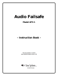
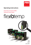
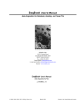
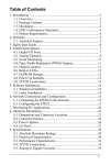
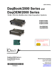
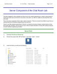
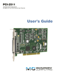
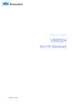
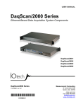
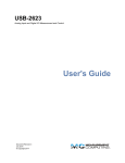
www.iotech.com
TECHTIP 60401
How to Use the Counter/Timer/Trigger Functions of IOtech
Data Acquisition Systems
Figure 1 : Measure Frequency
INTRODUCTION
The counter and timer functions provided
with numerous IOtech products let users
measure either the frequency or the period
of an input signal, and the total number of
pulses or cycles captured in a specified time
period. These functions are enabled when
the digital I/O ports are set up as inputs
using the supplied software package.
Counter and timer functions can be programmed to start and stop external hardware (or software) when certain logical conditions in the data acquisition system have
been met, such as turning on a valve after a
specific number of pulses are counted in a
particular time period.
Built-in timers also provide “pulse stream
output” signals when the digital I/O
ports are programmed as outputs. These
timers provide precise and stable output
signals and should be used for all
applications instead of any softwaregenerated timing signals.
Given: T1
Gate Signal
T1
Pulse Train Continuous Input
f1
frequency = number of pulses/unit time
Find: f1
Sample of Pulse Train
N1 pulses
counted
f1 =
N1
T1
The frequency (f) of a pulse train is determined by counting the number of pulses (N) captured
during the gate time (T). For example, when the number of pulses captured during a gate time
of one second is 100, then the frequency of the pulse train is 100 Hz.
Figure 2: Measure Total Count
Given: T1
Gate Signal
T1
Pulse Train Continuous Input
DISCUSSION
The input to a counter is typically a pulse
train. A counter measures the number of
input pulses during a given time period and
then determines the frequency of the signal. See Figure 1. Also, a counter counts the
absolute number of input events, pulses, or
cycles during a given time period and
outputs the results as a total number. See
Figure 2. A timer measures the time period
required for a preprogrammed number of
Find: N1
Computed number of pulses N1
in period T1
N1
A counter can determine the total number of pulses (N) in a pulse train during a specified time period
(T). For example, when the frequency (f) of a pulse train at the input is 500 Hz, and the time period
is programmed to 3 minutes, then the software calculates the number of pulses to be 90,000.
www.iotech.com • IOtech, Inc. • 25971 Cannon Rd • Cleveland, OH 44146 • (440) 439-4091 • Fax (440) 439-4093 • [email protected]
cycles of input signals to occur. See Figure 3.
Lastly, a trigger either initiates the start of a
sequence or terminates a sequence of events
or pulses. See Figure 4.
Figure 3: Measure Period or Time
Given: N1
Input Signal
Counter-Timer Functions
The total count that the data acquisition
system can handle depends on the counter
circuit’s number of bits. For example, a
4-bit counter (2 4) can totalize only
16 pulses before resetting, but a 16-bit
counter (216) can totalize 65,535 pulses,
and a 24 bit counter (224) can totalize
16,777,216 counts. Counters can be programmed to count up or down.
Counter stages can be cascaded to increase
the count by many powers of two with a
carry bit. That is, when the first counter
reaches its maximum count, it outputs a
carry bit to the next counter in the cascade
which then increments its count by one.
For example, adding two 4-bit counters to
the 24-bit counter (now 32-bits) increases
the total count to more than 4 billion, or
exactly 4,294,967,296 pulses.
N1 pulses
Find: T1
T1
Time to count N1 pulses
one period
The time (T) required to allow a specified, programmed number of pulses (N) to be captured
is called the period, and is computed by the software. For example, when the data acquisition
system is programmed to calculate the time period for 500 pulses of an 8.333 Hz signal to be
captured, the software will determine it to be 60 seconds.
Figure 4: Trigger Signals
Given: Triggers
Tr1 = Start Count
Tr2 = Stop Count
Pulse Train Continuous Input
DaqBooks® can synchronously scan four
16-bit counter input channels. Moreover,
the four channels can be cascaded into
two 32-bit channels. For either cascaded
or non-cascaded counter channels, each
channel can be configured for:
Pulse-Counting Mode: specifies that
each counter should be cleared or
reset to zero after being read and
placed into the input scan list.
Totalize-Counting Mode: specifies that
each counter is to free run and will
not be cleared during the input
acquisition.
The counter requires a trigger to start it
counting after being programmed. For
example, a trigger signal can be initiated
when one of the other counters reaches or
exceeds a programmed number, or remains at a prescribed number. Any of the
built-in counter-totalizer channels can be
programmed as a trigger source.
The counter inputs provided on the P3
connector of certain IOtech products
count the number of pulses per sample
period. For example, when a 1000-Hz
square wave enters the counter and is
sampled twice per second, the following
Number of pulses (N),
Period (T), or frequency (f)
calculated between Triggers
Find: N, T, or f
N, T, or f
A trigger signal can be programmed to start and stop the acquisition of a number of events.
For example, the period between a start and a stop trigger can be programmed to determine
the period or frequency of an input signal, or just the total number of pulses that occurred
during that time.
takes place, depending on the option set
in the counter input module in the
DASYLab® software:
A.
Count Mode = Single Value: The
counter module provides a value of
500 because in 1/2 second, it counts
500 pulses. In this mode, the counter
resets every sample period.
B.
Count Mode = Running: The module
provides a constantly increasing
number of counts (500 per each 1/2
second). In this mode, the counter will
not reset until a new acquisition begins
or it reaches its maximum count.
C.
Count Mode = Frequency: Provides
a constant frequency measured in
pulses per second. However, the
resolution of that frequency depends
upon the ratio between the input
frequency and the sampling
frequency. That is, the higher the
ratio, the higher the resolution. For
example, when the input frequency
is 1000 Hz and the sample frequency
is twice per second, it provides a
resolution of one part in 500. But if
the sample frequency is changed to
50 times per second, it provides a
resolution of only one part in 20.
2
www.iotech.com • IOtech, Inc. • 25971 Cannon Rd • Cleveland, OH 44146 • (440) 439-4091 • Fax (440) 439-4093 • [email protected]
Counters are frequently used for measuring displacement with
digital encoders. (Refer to TECHTIP 60101.) They are also used
to count a preprogrammed number of pulses before sending an
output signal to turn on or off an external device, such as a relay.
Normally, software-based triggering produces long latencies from
the time that a trigger is detected until the actual data acquisition
starts. However, the DaqBook circuitry uses pre-trigger data that
circumvents this condition. That is, by the time the PC detects a
command trigger to begin collecting data, thousands of readings
may already have taken place. The DaqBook driver then automatically looks back to that location in memory where the original
command was given in real time, and the acquired data that are
presented to the user actually begins at that point. The latency in
this mode equals one scan cycle.
When required to measure the frequency of pulse inputs with
the same resolution independent of sampling rate, use an
IOtech DBK7™, a 4-channel frequency input module, instead of
the counters in the Daq device itself.
Triggers
Pre and Post-Triggering Modes
Triggering is one of the most critical aspects of acquiring data.
IOtech equipment supports a full complement of trigger modes
to accommodate a wide variety of applications.
Six modes of triggering are supported, which provides a wide
variety of options to accommodate any measurement requirement. The pre-triggering modes require a software-based trigger
to initiate an acquisition. Moreover, when the pre-trigger mode
is enabled, the hardware triggers are disabled. That is, only
software-based trigger modes are available when the pre-trigger
mode is active.
Hardware Analog Triggering: Many data acquisition system specifications claim to support analog triggering, but actually rely on
the attached personal computer (PC) to take readings and make
a decision, which can lead to uncertain and possibly long
latencies. By contrast, IOtech products use true analog triggering. In this case, the user programs the trigger level, which sets
a DAC. The DAC’s output voltage is then compared in hardware
to the analog input level on the selected channel. The analog
trigger latency is guaranteed to be less than 5 microseconds,
significantly shorter than most data acquisition devices. Any
analog channel can be selected as the trigger channel. The user
can program the level and select either the rising or falling edge
of the trigger signal.
No Pre-Trigger, Post-Trigger Stop Event: This is the simplest of
modes. The system starts acquiring data when it receives the
trigger and stops acquiring data when it receives the stop trigger.
Fixed Pre-Trigger with Post-Trigger Stop Event: In this mode, users
specify the number of pre-trigger readings to be acquired, after
which, acquisition continues until it receives a stop trigger.
No Pre-Trigger, Infinite Post-Trigger: No pre-trigger data are acquired
in this mode. Instead, data are acquired beginning with the
trigger signal and terminates when the operator issues a command
to halt the acquisition.
Digital Triggering (Connector P1): A separate digital trigger input
line is provided, allowing TTL-level triggering with latencies of
less than 5 microseconds. The logic levels (1 or 0) and the
leading or trailing edge can be selected for the discrete digital
trigger input. The digital trigger input is labeled TTLTRG.
Fixed Pre-Trigger with Infinite Post-Trigger: Users specify the
amount of pre-trigger data to acquire, after which the system
continues to acquire data until the program issues a command to halt acquisition.
Digital Pattern Triggering (Connector P2 [and P3 when available]):
The DaqBooks support digital pattern triggering, where users
can designate any of the digital input ports as the trigger port.
The programmed digital pattern – including the ability to mask
or ignore specific bits – is then compared to the actual input
until a match is detected, after which the sequencer begins the
scan sequence.
Variable Pre-Trigger with Post-Trigger Stop Event (Driver Support
Only): Unlike the previous pre-trigger modes, this mode does
not have to satisfy the pre-trigger number of readings before
recognizing the trigger. Thus the number of pre-trigger readings
acquired is variable and depends on the time of the trigger
relative to the start. In this mode, data continues to be acquired
until the stop trigger is detected.
Counter Triggering: When one of the counters reaches, exceeds, or is within a programmed number it can generate the
trigger. Any of the built-in counter/totalizer channels can be
programmed as a trigger source.
Variable Pre-Trigger with Infinite Post-Trigger (Driver Support
Only): This is similar to the mode just described, except that
the acquisition terminates when it receives a command from
the program.
Software-Based Triggering: Software-based triggering differs
from the hardware modes described above because the PC
interrogates the readings (analog, digital, or counter) in order
to detect the trigger event. The advantage of this mode is to
permit triggering based on more complex applications, such
as on a specific temperature, which was derived from acquiring at least two analog measurements and calculating the
measured temperature with linearization algorithms.
Stop Trigger: Any of the software trigger modes described above
can be used to stop an acquisition. Thus, an acquisition can be
programmed to begin on one event, such as a temperature level,
and then stopped on another, such as a digital pattern.
3
www.iotech.com • IOtech, Inc. • 25971 Cannon Rd • Cleveland, OH 44146 • (440) 439-4091 • Fax (440) 439-4093 • [email protected]
Whether the DaqBook is using its internal-scan clock or external
clock input, it can be programmed to output the clock on the
SYNC connector. In either case, the unit behaves like a synchronization master. Other DaqBook units that are connected to the
master through a SYNC port should be programmed as synchronization slaves and obtain their scan period from the SYNC port.
When the slave unit must be triggered at the same time as the
master unit, then the slave should use TTL Trigger as its trigger
source. This master-slave connection through SYNC ports does
not support the pre-trigger mode of operation. Only post-trigger
data can be collected and time correlated between the units.
SYNCHRONOUS I/O OPERATIONS
Synchronizing Multiple Units: DaqBook/2000® and DaqOEM/2000™
series devices can be connected and synchronized via their SYNC
ports with cables CA-74-1 or CA-74-5. The units also can be scansynchronized and triggered from any other SYNC-connected unit.
(See Figure 5.)
Figure 5: Synchronization Concept Block Diagram
SYNC
TTL trigger input
Composite trigger output
Synchronous Input Operations: DaqBooks permit synchronous
scanning and acquisition of analog, digital, and counter input
data with aggregate scanning rates up to 200 kHz. The analog
input data can be either sent through the “main unit” or
expansion modules from P1-compatible analog input modules.
Similarly, the digital input data can be obtained through the
8-bit P2 port (Intel 8255 programmable peripheral interface)
“main unit,” or P2-compatible DBK digital input expansion
modules. For DaqBook/2001 ®, DaqBook/2005 ®, and the
DaqOEM™ equivalents, 16-bit digital inputs on P3 are used.
DaqBook/2020® has no P3 connector, but uses BNC connectors
for the same function.
Synchronization master
SYNC
Extrenal clock input
Scan clock output
Synchronization master
The SYNC features are software programmable. For more information, see the “Using Multiple Devices” and the
daqAdcSetClockSource sections of the “Programmer’s Manual”
(p/n 1008-0901).
Figure 6: Synchronization Model for DaqBooks
Special Synchronization Considerations:
Select
EXTCLK
Clock
divider
TRIGGER
When a DaqBook is programmed as a synchronization
slave, the TTL trigger source is automatically derived from
the SYNC port of the master.
•
When a DaqBook is programmed as a synchronization
maser, it outputs its trigger signal via the SYNC port.
•
When synchronizing two or more DaqBooks, the slave
units should contain at least 0.1 microsecond of dead time
in the scan period. Dead time means a period when no
channels are sampled. This accommodates fundamental
differences in the clocks for each DaqBook. However, the
maximum aggregate scanning rate drops from 200 kHz to
196.078 kHz.
•
All DaqBooks that are connected through SYNC cables can
be scan-synchronized to within 0.1 microseconds of one
another.
•
A maximum of 4 units can be synchronized; scansynchronous (post trigger).
•
SYNC cables shall not exceed a total combined length of
15 feet (4.57 m).
Acquisition
engine
G-SYNC
SYNC
•
Synchronization
master
Start of scan
Select
SYNC
TTLTRG
G-TRIG
Synchronization
master
Triggered
Note: For DaqBook/2001 and DaqBook/2005, the clock signal is on P1, pin 20,
and the trigger signal is on P1, pin 25. For DaqOEM/2000 Series devices, the
clock signal is on JP1, pin 2, and the trigger signal is JP1, pin 12.
The DaqBook/2020 uses BNC connectors for EXTCLK and TRIGGER
inputs.
One of three signals controls the DaqBook’s acquisition scan
rate: the internal acquisition pacer clock, an external acquisition pacer clock, or the global sync (G-SYNC) input from the
SYNC ports. Both the SYNC connector input and the external
clock input can be divided down. When a DaqBook is in the
Master Mode, both the trigger state and the scan timing signals
are sent to the SYNC port, and the global trigger (G-TRIG) is
selected instead of the TTL trigger input.
4
www.iotech.com • IOtech, Inc. • 25971 Cannon Rd • Cleveland, OH 44146 • (440) 439-4091 • Fax (440) 439-4093 • [email protected]
Counter Input Channels (CTR0, CTR1, CTR2, CTR3): DaqBooks
and DaqOEMs have inputs that accept and read counter signals
when the counter channel is not configured for synchronous
acquisition. During synchronous operation, the four 16-bit
counter channels can be used individually or cascaded into two
32-bit counter channels. For either cascaded or non-cascaded
counter channels, each channel can be configured for “ClearOn-Read” mode, which specifies that each counter should be
cleared (reset to 0) upon being read, and “Continuous Totalize”
mode, which specifies that each counter is to free-run and not
be cleared during the read operation.
ASYNCHRONOUS I/O OPERATIONS
Each DaqBook allows:
A. Asynchronous operation of any counter or digital channel
that is not currently configured for synchronous acquisition
B.
Asynchronous output signals to be delivered to all D/A channels
that are not currently configured for waveform output
Likewise, for DaqBook/2001, /2005, and DaqOEM/2001 and
/2005, the P3 port can be used for asynchronous input and
output. In addition, the timer outputs can be programmed at
any time regardless of the state of the other channels.
Digital I/O Channel Interface Requirements: The specific electrical
interface requirements for P2 and P3 connectors vary among the
various IOtech products. When linking directly to these connectors, consult the individual products’ instruction manual. For
example, the outputs for DaqBook™ and DaqOEM™ products are
not the customary open-collector transistors that can drive
external relays by sinking current from an external power
supply. Rather, these digital I/O interfaces are designed to drive
external logic circuits with the following requirements:
Digital I/O Channels
Local 8255 Channels (Connector P2 or JP2, Port A, Port B, Port C.):
The DaqBooks contain an Intel 8255 PPI (programmable peripheral interface) within the digital I/O logic on the P2 port. The
Intel 8255 supports three 8-bit wide ports for I/O and one 8-bit
wide port for configuration. The configuration port sets the
other three 8-bit ports for either input or output.
Input Characteristics: 100 Ohms in series, 20 pF to common
Local 16-Bit P3 Port (P3 or JP3, Digital 0 through Digital 15): The
P3 port can be used as either an input or an output port without
requiring configuration. The port simply outputs when written
to and inputs when read.
Input Protection: ±8kV ESD clamp diodes in parallel
I/O Levels: TTL
Sampling Rate: 200 kHz maximum
Output Characteristics: Output 12 mA per pin,
200 mA total continuous (per bank of 24 outputs)
Expansion Digital I/O: DaqBooks expand their digital I/O via the
P2 port and connect to IOtech’s digital I/O expansion modules.
These modules are discussed in the DBK™ Option Cards and
Modules User’s Manual (p/n 457-0905). When using the digital
I/O expansion modules, the local Intel 8255 digital I/O on P2 is
inaccessible. The expansion modules provide additional Intel
8255 ports and input isolation for applications that require
these added capabilities.
The equivalent circuit of this digital output comprises a latch
and buffer followed by a 100 Ohm resistor in series with the
output terminal. The buffer output nominally provides 0 to 5V
(specifically 0.4 to 4.8V) and can source up to 12 mA. At 12 mA,
expect a 1.2V drop across the 100 Ohm series resistor. Because
of this relatively low output current, users must provide intermediate buffers to drive relays or other higher current devices.
Pulse Stream Output using Timers (Timer0, Timer1): DaqBook
timers can be programmed to generate output pulses. The timers
can be set at any time regardless of the state of any other
channel. For the DaqBook/2020, the outputs are through BNC
connectors T0 and T1. For DaqBook/2001 and /2005, the timer
outputs are through the P3 connector; pin 15 for Timer 0, and
pin 16 for Timer 1. For DaqOEM/2001 and/2005, the timer
outputs are through the JP3 header; pin 29 for Timer 0 and pin
31 for Timer 1.
Many of IOtech’s modules and products, such as the LogBook™,
have TTL-compatible outputs, but can drive only 1 mA or less. If an
application requires that these digital outputs control a solid-state
relay or other relatively high-power device, users must provide
a compatible TTL-to-relay converter. Such relays may be
found at http://www.securityideas.com/alrbrelmod3.html.
A four-channel TTL-compatible relay is also available at
http://www.winfordeng.com/products/rly104.php.
The digital input ports are comprised of true TTL circuits, but
they do not contain over-voltage protection. The input voltage
is limited to a maximum of 5 Vdc: Higher signal voltages can
damage the input circuitry.
5
www.iotech.com • IOtech, Inc. • 25971 Cannon Rd • Cleveland, OH 44146 • (440) 439-4091 • Fax (440) 439-4093 • [email protected]
The 16 high-speed digital I/O lines and the additional digital I/O
control lines can be used for real-time digital peripherals such as
expanded digital input, or current and voltage-mode DAQs.
INSTALLATION AND SETUP SUMMARY
Logbooks™, DaqBooks®, and DaqBoards™ contain the three
I/O port connectors, P1, P2, and P3. These connectors are
located either on the front or rear panel of the books or on the
edge of the boards. P1 is an analog input port connector for
DBK type cards. It handles ±10 Vdc and 0 to 20 Vdc; digital
calibration; number of channel readings in a scan (sequencer
depth); and a protocol that lets the DBK cards or modules
identify themselves and carry their own calibration data. (See
LogBook users manual, page 4-6.)
The optional, internal four-channel, 16-bit waveform and control
±10 Vdc DAQs on P3 are initially set up to a static, preprogrammed
voltage at the beginning of an acquisition, and may be used for
waveform or control outputs.
Contact Information
IOtech, Inc.
25971 Cannon Road
Cleveland, Ohio 44146
Phone: 1-440-439-4091
Fax: 1-440-439-4093
Email: [email protected]
P2 is the digital I/O port connector. It is used with various kinds
of digital signals, such as alarm outputs to identify specified
levels that were detected in the acquired data. For autonomous
operation without an attached PC, P2 ports may be preset as
outputs before the acquisition.
P3 is the port connector for measuring pulse, frequency, and
high-speed digital signals. It contains four 16-bit pulse counter
channels that can be scanned along with the analog inputs.
It also handles four optional, internal 16-bit ±10 Vdc analog
output channels for waveform or control, or additional control lines for external analog output expansion. It also contains digital I/O control lines for high-speed digital input and
output signals.
6
www.iotech.com • IOtech, Inc. • 25971 Cannon Rd • Cleveland, OH 44146 • (440) 439-4091 • Fax (440) 439-4093 • [email protected]
1
2
3
4
5
6
7
8
9
10
11
12
13
14
15
16
17
18
19
TABLES
20
21
22
23
24
25
26
27
28
29
30
31
32
33
34
35
36
37
The P1, P2, and P3 pin-out tables that
follow show how the signals connect to
LogBooks with a CA-37-x cable (D-shell
37-pin female connector), or a DBK11 screwterminal card with component sockets.
Table 1: P1 connector pin-out assignment for LogBooks
Pin
1
2
3
4
5
6
7
8
9
10
11
12
13
14
15
16
17
18
19
20
21
22
23
24
25
26
27
28
29
30
31
32
33
34
35
36
37
Signal Name
+5 PWR
-15 VDC with diode
CHS 3
CHS 1
GS 1
GS 0
POWER GND
NEGREF (-5 V)
POSREF (+5 V)
N/C
CH 7 LO IN/CH 15 HI IN
CH 6 LO IN/CH 14 HI IN
CH 5 LO IN/CH 13 HI IN
CH 4 LO IN/CH 12 HI IN
CH 3 LO IN/CH 11 HI IN
CH 2 LO IN/CH 10 HI IN
CH 1 LO IN/CH 9 HI IN
CH 0 LO IN/CH 8 HI IN
L.L. GND
PCRCLK
+15 VDC with diode
CHS 2
CHS 0
DIG IN 1
DIG IN 0
SSH
CAL24
L.L. GND
L.L. GND
CH 7 HI IN
CH 6 HI IN
CH 5 HI IN
CH 4 HI IN
CH 3 HI IN
CH 2 HI IN
CH 1 HI IN
CH 0 HI IN
Description for P1 Pin Use
+5 V supply @ 0.100 A
-15 V supply @ 0.150 A
Channel select line for expansion cards
Channel select line for expansion cards
Gain select line for expansion cards
Gain select line for expansion cards
Digital ground
-5.0000 VDC @ 0.005 A reference used for various DBKs
+5.0000 VDC @ 0.005 A reference used for calibration with optional 4-channel D/A board
No Connection
Ch 7 LO IN (differential mode)/ch 15 HI IN (single-ended mode)
Ch 6 LO IN (differential mode)/ch 14 HI IN (single-ended mode)
Ch 5 LO IN (differential mode)/ch 13 HI IN (single-ended mode)
Ch 4 LO IN (differential mode)/ch 12 HI IN (single-ended mode)
Ch 3 LO IN (differential mode)/ch 11 HI IN (single-ended mode)
Ch 2 LO IN (differential mode)/ch 10 HI IN (single-ended mode)
Ch 1 LO IN (differential mode)/ch 9 HI IN(single-ended mode)
Ch 0 LO IN (differential mode)/ch 8 HI IN (single-ended mode)
Low-level ground (analog ground - use with analog inputs and outputs)
Pacer clock output/input
+15 V supply @ 0.150 A
Channel select line for expansion cards
Channel select line for expansion cards
Digital input bit 1
External TTL trigger input
Simultaneous Sample and Hold Output
Calibration output (+24 V @ 0.010 A)
Low-level ground (analog ground - use with analog inputs and outputs)
Low-level ground (analog ground - use with analog inputs and outputs)
Ch 7 HI IN (single-ended mode or differential mode)
Ch 6 HI IN (single-ended mode or differential mode)
Ch 5 HI IN (single-ended mode or differential mode)
Ch 4 HI IN (single-ended mode or differential mode)
Ch 3 HI IN (single-ended mode or differential mode)
Ch 2 HI IN (single-ended mode or differential mode)
Ch 1 HI IN (single-ended mode or differential mode)
Ch 0 HI IN (single-ended mode or differential mode)
7
www.iotech.com • IOtech, Inc. • 25971 Cannon Rd • Cleveland, OH 44146 • (440) 439-4091 • Fax (440) 439-4093 • [email protected]
1
2
3
4
5
6
7
8
9
10
11
12
13
14
15
16
17
18
19
20
21
22
23
24
25
26
27
28
29
30
31
32
33
34
35
36
37
Table 2: P2 connector pin-out assignment for LogBooks
Pin
1
2
3
4
5
6
7
8
9
10
11
12
13
14
15
16
17
18
19
20
21
22
23
24
25
26
27
28
29
30
31
32
33
34
35
36
37
Signal Name
IR INPUT
IR ENABLE
PORT B 7
PORT B 6
PORT B 5
PORT B 4
PORT B 3
PORT B 2
PORT B 1
PORT B 0
GND
N/C
GND
N/C
GND
N/C
GND
+5 V
GND
+5 V
GND
PORT C 7
PORT C 6
PORT C 5
PORT C 4
PORT C 3
PORT C 2
PORT C 1
PORT C 0
PORT A 7
PORT A 6
PORT A 5
PORT A 4
PORT A 3
PORT A 2
PORT A 1
PORT A 0
Description for P2 Pin Use
Interrupt line input (no functions to access this)
Interrupt line enable (no functions to access this)
Digital input/output – port B bit 7
Digital input/output – port B bit 6
Digital input/output – port B bit 5
Digital input/output – port B bit 4
Digital input/output – port B bit 3
Digital input/output – port B bit 2
Digital input/output – port B bit 1
Digital input/output – port B bit 0
Digital ground
Pin not connected/not used
Digital ground
Pin not connected/not used
Digital ground
Pin not connected/not used
Digital ground
+5 V supply @ 0.100 A
Digital ground
+5 V supply @ 0.100 A
Digital ground
Digital input/output – port C bit 7
Digital input/output – port C bit 6
Digital input/output – port C bit 5
Digital input/output – port C bit 4
Digital input/output – port C bit 3
Digital input/output – port C bit 2
Digital input/output – port C bit 1
Digital input/output – port C bit 0
Digital input/output – port A bit 7
Digital input/output – port A bit 6
Digital input/output – port A bit 5
Digital input/output – port A bit 4
Digital input/output – port A bit 3
Digital input/output – port A bit 2
Digital input/output – port A bit 1
Digital input/output – port A bit 0
Note: No local lines are available if digital expansion cards are in use.
8
www.iotech.com • IOtech, Inc. • 25971 Cannon Rd • Cleveland, OH 44146 • (440) 439-4091 • Fax (440) 439-4093 • [email protected]
1
2
3
4
5
6
7
8
9
10
11
12
13
14
15
16
17
18
19
20
21
22
23
24
25
26
27
28
29
30
31
32
33
34
35
36
37
Table 3: P3 connector pin-out assignment for LogBooks
Pin
1
2
3
4
5
6
7
8
9
10
11
12
13
14
15
16
17
18
19
20
21
22
23
24
25
26
27
28
29
30
31
32
33
34
35
36
37
Signal Name
IR INPUT
IR ENABLE
HSD 7
HSD 6
HSD 5
HSD 4
HSD 3
HSD 2
HSD 1
HSD 0
GND
C/DWRRDTMR 0 OUT
TMR 1 OUT
CNT 2 IN
CNT 0 IN
+15 VDC
+5 V
N/C
HSD 15
HSD 14
HSD 13
HSD 12
HSD 11
HSD 10
HSD 9
HSD 8
AGND
AOUT0 / Scan
AOUT1 / Trigger
AOUT2 / Clock
AOUT3 / DigOut
CNT 3 IN
CNT 1 IN
-15 VDC
Description for P3 Pin Use
Interrupt line input
Interrupt line enable
High-speed digital I/O bit 7 (low byte)
High-speed digital I/O bit 6 (low byte)
High-speed digital I/O bit 5 (low byte)
High-speed digital I/O bit 4 (low byte)
High-speed digital I/O bit 3 (low byte)
High-speed digital I/O bit 2 (low byte)
High-speed digital I/O bit 1 (low byte)
High-speed digital I/O bit 0 (low byte)
Digital ground
Timer 0 output
Timer 1 output
Counter 2 input
Counter 0 input
+15 V supply @ 0.050 A
+5 V supply @ 0.100 A
Pin not connected/not used
High-speed digital I/O bit 15 (high byte)
High-speed digital I/O bit 14 (high byte)
High-speed digital I/O bit 13 (high byte)
High-speed digital I/O bit 12 (high byte)
High-speed digital I/O bit 11 (high byte)
High-speed digital I/O bit 10 (high byte)
High-speed digital I/O bit 9 (high byte)
High-speed digital I/O bit 8 (high byte)
Analog ground
Analog output 0, optional LBK2: 16-bit, 100 kHz, ±10 VDC DAC
Analog output 1, optional LBK2: 16-bit, 100 kHz, ±10 VDC DAC
Analog output 2, optional LBK2: 16-bit, 100 kHz, ±10 VDC DAC
Analog output 3, optional LBK2: 16-bit, 100 kHz, ±10 VDC DAC
Counter 3 input
Counter 1 input
-15 V supply @ 0.050 A
9
www.iotech.com • IOtech, Inc. • 25971 Cannon Rd • Cleveland, OH 44146 • (440) 439-4091 • Fax (440) 439-4093 • [email protected]