1
Hardware Description
than 31 days, including corrections for leap year. The clock operates in
either the 24-hour or 12-hour format with AM/PM indicator. The DS1307
has a built-in power sense circuit that detects power failures and
automatically switches to the battery supply.
DC-DC Converter
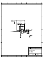
The MAX1674 step-up DC-DC converter features a built-in synchronous
rectifier, which improves efficiency and reduces size and cost by
eliminating the need for an external Schottky diode. Quiescent supply
current is only 16µA. The input voltage ranges from 0.7V to Vout, where
Vout can be set from 2V to 5.5V. Start-up is guaranteed from 1.1V inputs.
The MAX1674 has a preset, pin-selectable output for 5V or 3.3V. On the
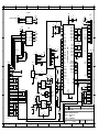
AVRcard, the output voltage is preset to 5V by R13, R24 is omitted.
Note: The MAX1674 may not be reversely fed. Therefore, never use battery
power supply and external supply simultainously. The step up converter
can be damaged.
RS-232 Driver
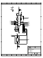
The MAX202E line driver/receiver is designed for RS-232 and V.28
communications in harsh environments. Each transmitter output and
receiver input is protected against ±15kV electrostatic discharge (ESD)
shocks,without latchup. The drivers and receivers meet all EIA/TIA-232E
and CCITT V.28 specifications at data rates up to 120kbps, when loaded in
accordance with the EIA/TIA-232E specification.
RS-485 Driver
The MAX485 is a low-power transceiver for RS-485 communication. Each
part contains one driver and one receiver. The driver slew rates of the
MAX485 is not limited, allowing it to transmit up to 2.5Mbps. These
transceivers draw between 120µA and 500µA of supply current when
unloaded or fully loaded with disabled drivers. The device operates from a
single 5V supply. Drivers are short-circuit current limited and are protected
against excessive power dissipation by thermal shutdown circuitry that
places the driver outputs into a high-impedance state. The receiver input
has a fail-safe feature that guarantees a logic-high output if the input is
open circuit.
Interfaces
I2C
Internal FRAM and RTC use I2C bus on PD0 (SCL) and PD1 (SCA). These
lines are pulled up to VCC by 2K7 resistors. This allows external I2C
devices to be attached directly. The DS1307 limits bus speed to 100kHz.
Serial
Communication
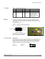
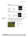
The two serial interfaces of the Atmega128 can be configured in various
ways:
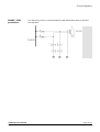
Serial port 1 (PE0, PE1) transmits to TTL and RS-232 simultainously.
Receives from TTL
Serial port 1 receives from RS-232.
Serial port 2 (PD2, PD3) transmits to TTL and simultainously to RS-232
Serial port 2 transmits to TTL and RS-485
Serial port 2 receives from TTL
Serial port 2 receives from RS-232
Serial port 2 receives from RS-485.
Note: Whenever reception from RS-232 or RS-485 is selected no TTL input
signal must be connected to the corresponding pins on the AVRcard as it
would interfer with the signal from transceivers Refer to chapter Jumpers.
AVRcard User Manual
Rev. 1.1a, 06.01.2004
page 8/19
www.avrcard.com