1
Electrical connection
5.3.1
AC voltage configuration
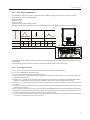
The SolarRiver–US may be easily configured for the different grid types commonly found in the U.S.
The SolarRiver–US is compatible with:
208V AC output
240V AC output
277V AC output
Common utility voltage configurations
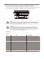
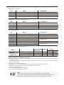
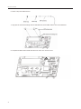
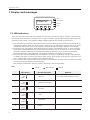
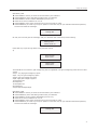
The figure illustrates commonly used utility types and connecting mode with SolarRiver–US inverter.
Grid standard
L1
L3
L2
208V~3PH-
Terminal
Wire
1
2
L1
L1
L3
L2
240V~Split-Phase
3
L1(*) L2(*) -
AWG#
L2
277V~3PH-Y
1
2
3
1
L1
L2
N
N
2
3
L1(*) -
4-6
If neatral(N) exists, SolarRiver-US is designed to automatically detect which utility type (except for utility)
it is feeding.
The SolarRiver-US may also be configured manually according to the local utility type.
5.3.2
AC wiring procedure
1.
2.
3.
4.
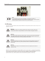
Turn off the main breaker/disconnect in the main utility breaker/disconnect box.
Turn the integrated DC disconnect OFF.
Remove interior breaker/disconnect panel cover.
If you are replacing an existing inverter, disconnect the wires for the AC line you are working within the
breaker/disconnect box.
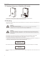
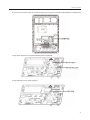
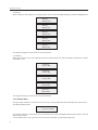
5. Install a 1 in. conduit fitting on the AC Grid knockout (the knockout on bottom of SolarRiver-US inverter).
Fasten the conduit fitting on the inside of SolarRiver-US inverter with the appropriate locknut.
6. Install a 1 in. conduit between the main breaker/disconnect box and the SolarRiver-US inverter AC Grid
knockout.
7. Pull the AC wires through the conduit from the interior of the breaker/disconnect box to the interior of the
SolarRiver-US inverter.
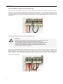
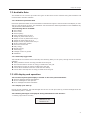
8. Connect the AC equipment-ground wire to the PE terminal labeled in the wiring zone of SolarRiver-US inverter.
9. Connect the 3 AC wires to the relative terminal block present inside the inverter and tighten them. The
AC wire connections should be done based on the type of AC grid.
10. Verify that all connections are correctly wired and properly torqued. Pull on the cable in order to make
sure that it is sufficiently fixed in the terminal.
19