1
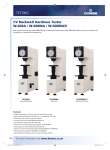
Digital Vickers Hardness Tester
MODEL ISH-DV50
USER’S MANUAL
www.insize.com
Contents:
I
General Description
II
Main Specifications
III
Installation and Commissioning
1. Working Conditions
2. Unpacking & Installation
3. Operation Panel & Menus
4. How to Operate
5. Tips & Special Attentions
IV
Accessories (Packing List)
www.insize.com
I.General Description
VICKER'S Hardness Tester with Digital Display is a new hi-tech product integrating mechanical
and photoelectrical technologies. As a substitute of traditional small-load Vicker’s hardness
tester, it features in easy operation and good reliability.
The following highlight some key features and functions:
− Integration of computer programming technology, high resolution optical measuring
system and photoelectrical technique;
− Soft key input;
− Light source adjustment;
− Selectable testing model, conversion tables, pressure-holding time, file number input and
data saving functions;
− Big LCD screen to display testing model, testing pressure, indention length, hardness
values, pressure holding time and numbers of tests:
− Date recording, test results recording and data processing;
− Printing output function;
− RS232 interface for PC connection.
− Camera for indention photographing and metallography
The tester is specially designed for testing minute, thin samples or parts after surface coating.
For research institutes, factories labs and QC departments, this is an ideal hardness testing
instrument for research or measuring purposes.
II. Main Specifications
Testing Pressure
Hardness Value Symbol
HV1, HV5, HV10 HV20
HV30 HV50
Hardness Value Range In Measure
Pressure Loading & Unloading
Magnification of Microscope
Pressure Holding Time
Minimum Measurable Unit
Maximum Height of Sample
Distance from Indenter’s Center to Outer Wall
Main Body Weight
Power Source
Machine Size (LxWxH)
9.8N(1kgf), 49N (5kgf)
98N(10kgf), 196N (20kgf)
294N(30kgf), 490N (50kgf)
Error Range in Display
±3.0%
±2.0%
5HV1~2500HV50
Automatic
100 x (for measuring)
0 ~60 s (1 second as input increment)
0.125 μm
160mm
135mm
approx. 40kg
AC220V/50Hz
(540x220x650)mm
III. Installation and Commissioning
1. Working Conditions:
a) Under room temperature between 10~35°C
b) Installed and leveled on a stable base
c) Placed in an environment free of vibration
d) Placed in an environment free of corrosive medium
e) Relative humidity not exceeding 65%
2. Unpacking & Installation
2.1 Remove the packing box and take out the main machine and accessory box.
2.2 Place the tester on a dedicated working table;
2.3 Take out the leveling screws out of the accessory box and fix them at the bottom of the
main body . Adjust the screws until the body is leveled.
www.insize.com
2.4 Lower the lifting screw and remove the filling piece between the lifting screw and the
indenter cap. Turn the handwheel further and make sure that the lifting screw can freely
turns within the hole on the working table. For the size of the hole to be opened on the table,
please refer to the following drawing:
200
500
∅ 90
Figure 3
2.5 Remove the gauze between machine top and indenter. Open the top cover and remove the
gauze which fastens the cam and lever. Then replace the top cover.
2.6 Open back cover and remove the gauze fastening the hanger and support. Get weights
from accessory box and install them in an order with Weight No.1 on the top. Then replace
the back cover.
2.7 Plug the power cord and turn on the switch. The tester is now ready for operation.
3.
Operation Panel & Menus
3.1 Key Functions (Figure 4)
4
5
ESC
PRI
0
1
Å
CLR
Figure 4
3.1.1
3.1.2
6
7
8
Ç
2
DEL
9
L+
y
3
È
Æ
L-
DISP
ENTER
START
Number Keys: Keys with 0,1,2…..as the 1st function
Function Keys: (mainly 2nd function keys)
4
Exit to main menu
ESC
ENTER
START
1st function: confirm 2nd function: start
6
2
Ç
5
1
È
3
Å
Direction keys
Æ
Printing out current data or saved data
PRI
7
Delete data of current test (including current number of tests)
DEL
9
Display data for current test
DISP
0
Clear
CLR
8
Increase brightness of light source
L+
y
Adjusting light source in testing
Decrease brightness of light source
Lwww.insize.com
To maximize ease in operation, the software is so designed that no shift key is required
between 1st and 2nd function conversion. Num keys become valid only when you are
requested to input numbers. Function keys are the main effective keys in working.
3.2. The Menus
Turn on the machine and the indicator on the left side of the printer lights up. After several
beeps, the screen appears like Figure 5. The Main Screen adopts the most common menu
format and interactive dialogue window format, and is thus very user-friendly.
Hardness
Dwell
Function
File
Main Menu
HV
HK
NOT-COV
Commands
CTAB1
CTAB2
9.8070N
Pressure
HV
CÆNOT COV
TIME: 10
Test Model Conversion Mode Holding Time
N0:00
Status bar
Number of tests
Figure 5
Scroll the highlighted bar through drop-down submenus and press [ENTER/START] to confirm.
For example, to select HV command, you scroll the highlighted bar by pressing [6/Ç] [2/È]
until HV is highlighted. Then press [ENTER/START] to confirm.
For all correct operation, a beep follows each key press. A prolonged buzz will give off in case
of any error in key pressing.
Normally, the motor is load relieved when the tester is turned off and screen shows as Figure 5
when the tester is turned on again. If the buzz goes off and stays on as soon as the machine is
turned on, then the motor is not yet loaded relieved. Wait until it is load relieved and the buzz
will stop. Only then can operation be conducted on the tester.
3.2.1 Status Bar
The first item is the indication of pressure, which can be selected by Pressure Change
Handwheel. The user can select the required pressure from 6 load steps from 2.94N to 98N.
The selected pressure will be displayed on the status bar.
For example, Figure 5 shows that the current pressure is 9.8070N. If we want to change the
pressure to 4.9035N, just turn the handwheel to 4.9035N and the display will change
accordingly on the status bar.
The second item shown on the status bar is test model: HV or HK.
www.insize.com
The third item is conversion mode and CÆNOT COV (as shown in Figure 5) means no
conversion.
The fourth item is pressure holding time which is now 10 seconds as shown in Figure 5.
The last item is number of tests.
3.2.2 Main Menu
3.2.2.1 MODEL ………………. Selection of test model
The items contained in the submenu includes:
HV
________
Test model of Vicker’s Hardness
HK
________
Test model of Knoop’s Hardness
NOT-COV ________ No conversion
CTAB1
________
Nonferrous metal conversion table (Figure 6)
CTAB2
________ Ferrous metal conversion table (Figure 7)
Hardness
HV
HK
NOT-COV
CTAB1
CTAB2
9.8070N
Dwell
Function
File
HRB
HV
HK
HB
HRF
HRG
HRE
HRK
HR15T
HR30T
HR45T
HS
TENSI
HV CÆHK
(1)
TIME: 10
N0:00
Figure 6
Select HV or HK by pressing the direction keys on the control panel and confirm by ENTER.
Press direction keys again until CATB1 is highlighted. Confirm and CATB1 will pop out a sub
menu which displays conversion tables for nonferrous metals. Select one conversion scale
and confirm again. When these steps are completed, the status bar will automatically
display the conversion model you have set. In Figure 6, the status bar displays HV CÆHK
which means conversion from Vicker’s hardness into Knoop’s hardness. The indication of
"(1)" on the right side indicates that conversion table for nonferrous metals is currently
selected.
Hardness
HV
HK
NOT-COV
CTAB1
CTAB2
9.8070N
Dwell
Function
File
HRC
HV
HK
HRA
HRB
HRD
HR15N
HR30N
HR45N
HS
TENSI
HK CÆHRA
(2)
TIME: 10
www.insize.com
Figure 7
N0:00
Select HV or HK by pressing the direction keys on the control panel and confirm by ENTER.
Press direction key again until CATB2 is highlighted. Confirm and CATB2 will pop out a sub
menu which displays conversion tables for ferrous metals. Select one conversion scale and
confirm again. When these steps are completed, the status bar will automatically display the
conversion model you have set. In Figure 7, the status bar displays HK CÆHRA which means
conversion from Knoop’s hardness into Vicker’s hardness. The indication of "(2)" on the right
side shows that conversion table for ferrous metals is currently selected.
3.2.2.2
DWELL……………….. Pressure holding time (in seconds)
Hardness
Dwell
Function
File
00S
05S
10S
15S
20S
25S
30S
40S
50S
60S
SET TIME
INPUT time:
9.8070N
HK CÆHRA
(2)
TIME: 10
N0:00
Figure 8
As shown in Figure 8, the pressure holding time can be selected from 10 choices from 0
second to 60 seconds. Toggle through the required holding time and confirm by ENTER. If the
required time is not available in the set range, select SET TIME command and a dialogue box
appears on the screen. You can input any time from 0 to 99 seconds and confirm. Your
selection or input will then be displayed on the status bar.
3.2.2.3
Function ……………. Function key
Hardness
Dwell
Function
File
Single
COMM
Reset
Print
Light +
Light -
9.8070N
HK CÆHRA
(2)
TIME: 10
Figure 9
www.insize.com
N0:00
Single machine operation is similar to that of other ordinary hardness testers because
operation is done through the internal mechanism and electronic features without connection
with any external equipment (i.e. external PC).
Use direction keys to select Single and confirm by ENTER key. Screen as Figure 8 will change
into single machine operation screen as shown in Figure 9.
3.2.2.3.1 Single……………… Single Machine Operation
Test
KEY
d1
d1:
d2:
d2
HV:
HRA (H):
9.8070N
HV CÆHRA
(2)
TIME: 10
NO:00
Figure 10
Figure 10 shows the single machine operation of the Vicker’s hardness tester. d1 and d2 are
the two diagonals of the indention which are measured by photoelectrical encoder. HV is the
Vicker’s hardness value and is automatically displayed as soon as d1 and d2 are measured.
HRA is the conversion scale which can be set as shown in Figure 6 or Figure 7. Similarly, other
scales can also be set through conversion tables. If no conversion scale is selected, the status
bar will display HV CÆNOT COV. In this case, only d1, d2 and HV are displayed under the
heading of Testing and no conversion scale is displayed. KEY stands for working status which
has 3 modes:
KEY
Stand by or task completed
Loading pressure
ΗCaution: During these two statuses, n
other manual operation is allowed.
Unloading pressure
In doing Knoop’s hardness testing, the testing procedure requires the measuring of d. Other
procedure and status remains similar to that of Vicker’s hardness testing (as shown in Figure
11).
www.insize.com
Test
KEY
d0
d:
HK:
HRA (H):
9.8070N
HK CÆHRA
(2)
TIME: 10
NO:00
Figure 11
3.2.2.3.2 COMM ………………. PC connection
This function allows the machine to be connected to a PC via RS232 interface and thus offers
the possibility in the development of new CCD hardness testers by either the manufacturer or
the user.
3.2.2.3.3 Reset ………………. Reset operation
Reset function is effective to the current testing data. Please note that, while testing one
sample after another, the reset command will cause the loss of the previous testing data. So,
please decide whether or not the previous data should be saved. For information regarding
data saving, please refer to Save command hereinafter.
However, testing one sample after anther without reset will cause the previous results to be
mixed into the current data and data confusion and miscalculation will occur.
In case of no saving is necessary, use reset function freely.
3.2.2.3.4 Print ……………… Printing function
This function allows the printing of current testing data.
3.2.2.3.5 Light + ………………..Increase the brightness of the light source
3.2.2.3.6 Light - ………………..Decrease the brightness of the light source
Light + and Light – are used to adjust the brightness while the tester is not in testing status.
Select the command and press ENTER to confirm. Then you will hear a beep every time you
press the ENTER key, indicating that the brightness is increasing or decreasing. When you
hear a continuous beep, the brightness is either maximized or minimized.
3.2.2.4
FILE ………………. File functions
3.2.2.4.1
Save ………………. Saving files
This function allows you to store the current testing data in a file. There can be as many as
28 files to store, numbered from 00 to 27. If you continue saving a file when 28 files are
already in store, the first file will be automatically deleted. (i.e. File 00 will disappear and the
www.insize.com
files will be stored in the order from 1 to 28.) New files are stored according to heir number
sequence.
Hardness
Dwell
Function
File
Save
SAVE
Load
Input File NO:
Display
DispNo.
DATEIN
9.8070N
HK CÆHRA (2)
TIME: 10
N0:01
Figure 12
As shown in Figure 12, a dialogue box will pop up when SAVE function is selected and you
need to input the file number. Please note that file number is input through num keys and
must contain 6 digits, which can be randomly decided by you. If the input number is the
same as one file number already in store, a warning will be given and the machine will ask if
you need to replace the old file. Press 0 for no and 1 for yes. Please see Figure 13 as an
example.
Hardness
Dwell
Function
File
Save
SAVE
Load
Input File NO:
Display
DispNo.
DATEIN
File N0 Exists!
OverWrite ?
NO:
0
YES: 1
9.8070N
HK CÆHRA (2)
TIME: 10
N0:01
Figure 13
3.2.2.4.2
Load ……………….. Open file
This function is used to open the stored files and display the content on the screen.
www.insize.com
Hardness
Dwell
Function
File
Save
LOAD
Load
Input File NO:
Display
DispNo.
DATEIN
9.8070N
HK
CÆHRA (2)
TIME: 10
N0:01
Figure 14
As shown in Figure 14, a dialogue box will pop up when Load is selected and you can then
input the file number, which must be one of the file numbers already in store. When a wrong
number is input, the screen will display “file not found”. Screen page as Figure 14 will appear
again, waiting for re-input. If the correct file number is input, the display changes into the
screen as shown in Figure 15 (demo display only) .
No
01
9.8070N
D1(um)
D2(um)
HV
48.313
48.313
HV N0: 02 1111111
TIME: 10
HRC (H)
794
N0:01
Figure 15
In the heading, No stands for number of tests while d1 and d2 the diagonals for measuring.
HV is the hardness value. The first No indication on the status bar contains 2 digits: the first
being the sequential number of the current file among all stored files while the second being
the actual file number for retrieving. The second NO indication on the status bar means the
www.insize.com
number of current tests. This tester can display testing data for as many as 19 tests. In
addition, we can use direction key “È”to see statistic results of the testing data (Figure 16).
DD stands for error repeatability, MAX for maximum value, MIN for minimum value and AVE
for average.
www.insize.com
DATE
AMOUNT
DD=0.00%
MAX=794
MIN=794
AVE=794
9.8070N
HV N0: 02 1111111 TIME: 10
N0:01
Figure 16
3.2.2.4.3
Dispall ……………. Display all data in store
When this function is selected, you can use Ç,È keys to go through all data in one file. Or,
you can use Æ, Å keys to go through all files. In the latter case, every press of the direction
key will increase or decrease the file number by 1. All the files are automatically stored in
number order when you save them.
3.2.2.4.4
DispNO. …………… Display the file numbers in store (Figure 17)
This function allows you to refer to the numbers of all files in store.
NO.
00
01
02
DISP
111111
222222
000000
Figure 17
3.2.2.4.5
DATEIN …………… Set the date for file saving
www.insize.com
Hardness
Dwell
Function
File
Save
Load
Display
DispNo.
DATEIN
SAVE
Input Date (mmddyy)
9.8070N
HK
CÆHRA (2)
TIME: 10
N0:01
Figure 18
As shown in Figure 18, a dialogue box will pop up when you select DATEIN function, waiting
for your input of date. Press the num keys to input the date in order of month, day and year.
The date must be input before you save the file because the date will not be saved together
with the file if you save the file before you input the date.
4. How to Operate
The switch panel is located on the right side of the machine. It has the power switch, RS232
interface, fuse seat and power socket. The RS232 interface enables communication with
periphery equipment. The fuse is of 1A/250V and serves the main electric circuit.
Find the power cord in the accessory box and plug it into the power socket as shown in Figure
19.
Fuse Seat
Power Switch
RS232 Interface
Power Socket
Figure 19
4.2
Turn on the power switch and the screen lights. Turn testing pressure change handwheel
to select the required testing pressure. Make sure that the loaded pressure is the same as
that shown on the screen. The wrong display will result in the wrong calculation. Gently
turn the handwheel to avoid impact damage. (See Figure 5 for reference display).
4.3
Then the screen will show the submenu under MODEL . Under MODEL heading there are
2 testing model options: HV (Vicker's ) and HK (Knoop's). Press Ç, È keys to highlight the
desired model and confirm by ENTER key. Meantime, you will see HV or HK is displayed
www.insize.com
on the status bar on the screen (See Figure 5 for reference display).
There are two hardness conversion tables following NOTÆCOV: CTAB1 and CTAB2.
CTAB1 is used for nonferrous metal while CTAB2 for ferrous metal. Select the desired
table by Ç,È keys and confirm with ENTER key. After the conversion tables are displayed
(Figure 6 and 7), use direction keys to highlight the desired table and confirm by ENTER
key. The selected hardness conversion scale will be displayed on the status bar then.
4.4
Press Æ key and the sub-menu under DWELL will pop out, which is for selecting pressure
holding time. There are 10 options from 00S to 60S and you can make your selection by
highlighting the desired time and confirming with ENTER. If you need to set the time in the
range of 0~99S, use direction keys to highlight SETTIME and confirm by ENTER. Then an
“INPUT time” prompt will appear on the screen and you may set the time with num keys.
(Note: Two digits are required in time input, e.g. 03 for 3S) Confirm your input by ENTER
key and the set time will appear on the status bar (as shown Figure 8).
4.5
Press Æ key and the submenu under FUNCTION will pop out, showing Single, COMM,
Reset, Print, Light + and Light – as the options. Light + and Light – are used to adjust the
brightness of light source in stand by mode. To increase or decrease the brightness,
highlight Light + or Light – and press ENTER. Each time you press ENTER, the brightness
is increased or decreased once. Keep pressing until the image is clear.
Reset is used to clear the current testing data. Please note that in single machine
operation mode, the reset key will cause loss of the testing data of the current sample
when you press reset to test another sample. So please make it sure whether you want to
save the current data. If not, press Esc to return to main menu. Then select and confirm
Reset function. If yes, return to main menu and select Save to store the file. In saving,
input the 6-digit file number by num keys and confirm by ENTER. When the current data is
saved, select and confirm Reset. Please note that the current data will cause calculation
confusion in the next test if it is not reset.
Select Print function to print out current testing data.
COMM is provided for communication with periphery equipment.
Select Single to enter working mode. Use direction keys to highlight this function and
confirm by ENTER. Then you will see display on the screen as Figure 10.
4.6
4.7
Turn the Indenter-Objective changing wheel, moving 10X Objective to the front of the main
body (optical magnification 100X in measuring mode).
Place the standard sample on the testing table right under the Objective. Turn the
Revolving Wheel (20) and the testing table rises. While the sample is getting closer to the
lower part of Objective, you may watch through the Micro Eyepiece. If the image gets
brighter when the table rises, then you will know that it is focusing in. Turn the handwheel
more gently until the image of the testing sample (or the sample surface) becomes sharply
distinctive. Now the tester is focused.
4.8
Maybe the image you see is still fuzzy, then you may adjust the front lens of the Eyepiece
until you see a sharp image (because the observers’ eyesight varies). If the testing
surface you see in the eyepiece is not evenly lighted, you may adjust 3 screws on the light
source device until it is centered. If the image gets too bright or too dark, press L +, L- keys
on the panel to adjust.
4.9
Turn the indenter-Objective change wheel until indenter spindle comes to the front. Press
START key on the panel and the machine starts pressure loading. You will see a
being
displayed in the upper right corner of the screen, which indicating pressure loading
www.insize.com
process. As soon as it completes loading, the machine starts pressure holding status. You
will see a countdown indicator shown in a box in the screen’s upper right corner. As soon
as the holding time is up, a
appears in the screen’s upper right corner, indicating the
pressure unloading process. A
appears in the upper right corner of the screen when
the unloading ends. The current testing is completed then.
Note: ℵ If the sample has a rugged surface or has multi facets, be careful when you move
the indenter, lest it hits the sample.
ℑIn case you forget to change the objective and you press START or the machine
starts working, DO NOT turn the Indenter-Objective change wheel. You have to
wait until the current test is completed. Otherwise, the machine will be SERIOUSLY
DAMAGED.
4.10
Turn the Indenter-Objective change wheel and move 10X Objective to the front. Observe
the image through the Eyepiece and adjust lifting screw to obtain a sharp image. Please
note that under the objective of 100X magnification, the depth of the indention may affect
the focal plane. But this is normal.
4.11
Move the scale marks of the Eyepiece towards each other. When the marks are closing to
the critical moment when light is just to be shut out, press CLR key on the panel and the
screen shows d1: 0, which is the so-called zero place.
4.12
Turn the handwheel on the right side of the eyepiece to move apart the scale marks. Then
turn the knob on the left side of the Eyepiece to move the left mark. When the inner side of
the left mark touches the intersection point to the furthest left of the indention, start moving
the right mark until its inner side touches the intersection point to the furthest right of the
indention. Press the testing button on the Eyepiece and the screen will display the current
testing data and the hardness value after conversion. If you are not sure about the
accuracy, repeat the testing procedure as described above.
4.13
Only after the first test (measuring) is done can you start next. The testing and measuring
procedure stipulates that the first indention will not be taken into recording. So, the
hardness value obtained in the measuring of the second indention will be recorded as the
first result. Then you will find that NO:00 changes to NO:01 on the Status Bar.
4.14
As only 60% of the vision observed through the Eyepiece is valid, the loaded pressure
needs to be reduced when the image of the indention appears too big. Otherwise, error
will occur to the measured result. If the indention you see through the Eyepiece is too
small, you may increase the pressure to enhance the measuring accuracy. (Note: The
load must not exceed allowed limit. Otherwise, the sample may be punched through.)
4.15
After several tests, if you need to check previous test data, press DISP key and the
required data and statistical results will appear on the screen. Then press ESC to resume
working status. Press START key and the machine will start the next testing procedure.
4.16
There are two printing functions available. The first printing command in the FUNCTION
menu will print out the current testing data. But it does not allow the printing of stored files
and data obtained in tests other than the current one (The “current test” refers to the test
provided that no change is made to pressure, no new file opened and no change in menu
selection.). 19 groups of data can be printed out in maximum.
The second print function is available via PRI key on the operation panel, which will print
out data contained in each stored file as required.
4.17
In Knoop's hardness test, the testing procedure stipulates that only d will be measured.
Except for that, the working procedure and status are similar to that of Vicker’s hardness
test. For screen display, refer to Figure 11.
www.insize.com
4.18
In storing current testing data, press ESC first to return to main menu. Then press Æ to
activate FILE menu on the screen. Among the five sub-commands, highlight SAVE and
confirm by ENTER. The “Input File No:” prompt will appear on the screen, waiting for your
input of file number. Input file number through num keys and the number must contain 6
digits. The 6 digits can be randomly selected. Input will not be accepted if it is less or more
than 6 digits. Confirm your input by ENTER and the current test data will be saved.
Note: ℵ Save command will be effective only after testing is done. Under non-working
status (i.e. no testing or measuring or after reset), the Save command is inactive.
ℑDATEIN is for recording when the file is saved. To use this function, you need to
highlight DATEIN and confirm by ENTER. The “Input Date (mm/dd/yy): _” prompt
will then appear on the screen, requesting the input of the date. The format for
date input must be standardized. For example, 04201998 will be the correct input
if the current data is 20 April 1998. Confirm by ENTER after date input. Then
highlight Save command and confirm to store the file with date information. The
stored date can be retrieved via file printing or the following commands in the FILE
menu.
4.19
Load allows to display the content of the required file. Move direction keys to highlight
Load and confirm by ENTER. The “Input File No:” prompt will appear on the screen. Input
the required file number through num keys and confirm by ENTER when input completes.
Then the content, data and calculation results contained in the selected file number will be
displayed. Use Ç,È keys to scroll through displays if there are a lot of data shown on the
screen. Similarly, calculation results displayed can also be browsed by pressing direction
keys. (Figure 14, 15, 16)
4.20
Dispall allows to display all files in store. 28 files can be stored in maximum by HVS-10.
Move direction keys to highlight Dispall and confirm by ENTER key. Use again Æ, Å keys
to browse data contained in all files one by one.
4.21
DispNO is used to display file numbers. Highlight DispNO and confirm by ENTER. 28 file
numbers (0~27) can be displayed in maximum. However, one screen page only allows 13
file numbers at one time and you may go to the next page via Ç, È keys.
4.22
As the machine can only store 28 files in maximum, you have two alternatives when you
want to save new files after the storage is full. If you continue saving a new file, the first file
in store will automatically be deleted. For example, if there are 28 files already in store with
numbers from 00~27, then file numbered 00 will be removed after you save the new file.
So the new file list in store becomes 01~28 and the last file will take on the file number 28.
The other alternative is to replace existing files in store. Use Save function and the stored
data will be totally replaced by the current data, file order and file number remaining
unchanged. (Figure 12, 13)
5. Tips & Special Attentions
5.1 Read the User’s Manual carefully before use. Pay attention to operation procedures and
notes so as to avoid instrument damages or human injuries.
5.2 Please DO NOT use unqualified persons to disassemble electric components, switches and
power sockets in order to avoid accidents.
5.3 DO NOT turn the Revolving Wheel when testing pressure is being loaded or has not yet been
unloaded. Otherwise, the machine and the diamond indenter will be damaged. You can turn
the Revolving Wheel only after you hear a beep which indicates that the pressure has been
unloaded.
5.4 While the machine is in the status of measuring, DO NOT load pressure. If you touch START
www.insize.com
by accident, DO NOT turn the Revolving Wheel until the loading is completed.
5.5 If the machine is not in use for a long time, gently push the indenter upwards several times
with your hand before starting the tester.
5.6 About the diamond indenter
ℵ The Diamond Indenter (1) and the Indenter Spindle are two critical parts of the tester.
Special caution is required in operation to avoid hitting the indenter.
ℑ To maintain testing accuracy, keep the indenter clean. Use absorbent cotton and alcohol
(or ether) to gently clean the indenter tip if it is contaminated by dust or oil.
5.7 About the Micro Eyepiece
ℵ Since people’s eyesight varies, the marks in the Eyepiece vision may be unclear to a new
observer. So, the new observer should adjust the lens of the Eyepiece slightly first to get
a sharp view of the inner side of the mark.
ℑ The Eyepiece is within the Eyepiece Tube and make sure that the micro eyepiece closely
contacts the eyepiece tube when you are turning the eyepiece 90° to measure the
diagonals of the indention. The measuring accuracy may be affected if the eyepiece is not
tightly contacting the tube.
5.8 About light source for microscope
ℵ The central position of the light source will directly affect the image quality of the indention.
If the image is fuzzy or unevenly lighted, you need to center the light source. Carefully
adjust the three screws to align the bulb center with that of the light source. (Figure 21).
Adjusting screw for centering
the light source
Figure 21
5.9 About the sample
Keep the sample surface clean. Any oil or dust on the surface will affect the measuring
accuracy. Use alcohol or ether to gently rub it clean.
6.0 About the microscope camera
ℵ The machine is equipped with a microscope camera which is used to take photographs of
the testing results on the material being tested. Remove the photographing cover on the
top cover before installing the camera. Take the camera out of the accessory box and
connect it onto the screw seat of the eyepiece.
ℑ Remove the standard lens of the camera and connect the camera with the lens hole. Make
sure the spring snaps locked.
ℜ Observe the surface through the micro eyepiece. When you see a sharp image, pull out
the Switching Lever for Photographing and Measuring (15) on the left side of the main
body and the light route is changed into photographing status.
℘ Observe again through the eyepiece of the camera. Slightly adjust the visibility tuning ring
or the Lifting Screw (7) to get a sharp image.
www.insize.com
⊗ Activate the shutter to take the photograph of the surface.
IV. Accessories (Packing List)
1. Main machine (including 1 micro Vicker’s indenter, 1 10X Measuring)
2. Testing table, weights and microscope accessory box
Weights
4 pieces
Big, medium and small “V” –shaped testing table
1 for each type
Leveling screws
4 pieces
Power cord
1
1
10X digital type micro eyepiece
Standard block in Vicker’s hardness
2 {1 for medium-hard (5Kg), 1 for
mediumhard(30Kg)}
Spare bulb
2
3. Quality Certificate
1
4. User’s Manual
1
5. Operation Manual for Printer
1
6. Spare FUSE(1A,2A)
2 for each type
Optional items:
Main body of the photographing apparatus
Photographing eyepiece (6.4X, 4X)
Shutter line
Dark box
Special film sheet cassette
DF-300X camera
www.insize.com
1
1 for each type
1
1
3
1