1
Installation and Operation Manual
For IP Access Card Reader
Remark
Please follow the user manual for correct installation and testing, if
there is any doubt please call our tech-supporting and customer
center.
Our company applies ourselves to reformation and innovation of
our products. No extra informing for any change. The illustration
shown here only used for reference, if there is any difference
please take the actual product as standard product.
CATALOG
Product Features ...............................................................1
Technology Parameters.....................................................1
Product Pictures................................................................1
Main Parameters................................................................2
Basic Operations ...............................................................2
1. IR controller operation ..............................................................2
2. Management card registration/ user card deletion mode.......6
3. Register/ delete user card with USB ........................................7
4. Digital system network..............................................................7
5. Card sending mode...................................................................8
6. Door magnetic and damper alarm............................................8
7. Read/ set all parameters by access control setting tools.......8
8. Notice.......................................................................................13
System Configuration......................................................14
Safety Precaution ............................................................15
Product Features
CRAC-C5-ICID is called access device, also used as card sender. It is used for
swiping IC/ ID card, also external connects with ID/IC card reader. Main interface:
485, USB, TCP/IP interface.
All parameters can be controlled or set by IR remote controller, also read or
set by access control setting tools. It can be used as an access device
independently, also connect with digital system.
Unlocking mode: exit button, IR remote controller and card swiping. Card
registration and deletion can be made by IR remote controller and management
card. The computer can be operate by connecting with USB or digital system. Also
have magnetic and tamper alarm function.
Technology Parameters
1. Voltage: DC 12V
2. Rated power: 4W
3. Standby power consumption: 2.5W
4. Operating temperature: -10℃~+50℃
5. Relative huminity: 20%~93%
6. IP Rating: IP55
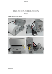
Picture
Picture
Power Indicator
SYS Indicator
Set Indicator
IR control receiving area
Card swiping area
-1-
Main Parameters
1. Factory default engineer password: 000000
2. Factory default unlocking time: 1s (0~9s)
3. No user card, management card or user password in factory default setting
4. Factory default module address 001 (0~9999), from 1~4 digits.
5. Factory default mode is outdoor panel, the default is Building 9, Unit 9, No.1
(9099901FFFFF)
6. 10 management cards can be registered at most, and set 100 groups of user
password.
7. User cards quantity: 60000
8. Factory default IP parameter: Access IP: 192.168.14.3
Access port: 8602
Access mask: 255.255.255.0
Access gateway: 192.168.14.1
Server IP: 192.168.14.18
Server port: 8600
Basic Operation
1. IR controller operation
(1) Power on
Power on access device, the system will make sound and light, then enter into
the standby mode, now the SYS indicator will flash.
(2) Unlock
Press “M” button, SYS indicator will light for a long time. Input 6 digits user
password, then press “#” button to confirm. If correct, it will sound a long tone and
unlock the door, otherwise it will exit with “di-di-di” tone.
(3) Setting mode
Press “C” button to enter into engineer password verification mode, then input
6 digits engineer password (the default engineer password is 000000), and press
“#” button to confirm. If the password is correct, the access device will sound a
long tone to enter into the setting mode, now SYS indicator will flash slowly.
Otherwise it will sound “di-di-di” tone to exit.
-2-
(4) Restore factory settings
Press “0+#” button to enter into restore factory settings mode under setting
mode, now SYS indicator will flash rapidly, then press “#” button to confirm, now
the access device will power on again to complete restoring factory settings.
(5) Change engineer password
Press “1+#” button to enter into engineer password setting mode, now SYS
indicator will flash rapidly. Input 6 digits new password, press “#” button to
confirm. Then press the same password again. If passwords are consistent, it will
sound a long tone; otherwise it will sound “di-di-di” tone, now set it again.
(6) Register user password
Press “2+#” button to enter into engineer password registering mode under
setting mode, now SYS indicator will flash rapidly. Input 6 digits new user
password, press “#” button to confirm. Then press the same password again. If
passwords are consistent, it will sound a long tone; otherwise it will sound “di-di-di”
tone, now set it again. 100 groups of password can be registered continuously.
(7) Delete all user passwords
Press “3+#” button to enter into deleting all user passwords mode under
setting mode, now SYS indicator will flash rapidly, then press “#” button, the
system will sound a long “di” tone to indicate all user passwords deletion is
successful.
(8) Set unlocking time
Press “4+#” button to enter into setting unlocking time mode under setting
mode, now SYS indicator will flash rapidly, input the unlocking time you want (0~
9s), then press “#” button to confirm, the system will sound a long “di” tone to
indicate unlocking time setting is successful.
(9) Register management card
Press “5+#” button to enter into registering management card mode under
setting mode, now SYS indicator will flash rapidly. Then make the card you want to
register closed to card swiping area, the system will sound a long “di” tone to
indicate the registration is successful, otherwise it will sound “di-di-di” tone to
indicate the card capacity is full or the card has been registered. 10 management
cards can be registered continuously. Press “*” or “#” button after registration, the
-3-
system will sound “di-di-di” tone to exit management card registration mode. If
press any button, the system will sound the same tone, but not exit management
card registration mode.
(10) Delete all management cards
Press “6+#” button to enter into deleting all management cards mode under
setting mode, now SYS indicator will flash rapidly. Then press “#” button to delete
all management cards, the system will sound a long “di” tone to indicate all
management cards deletion is successful.
(11) Register user card
Press “7+#” button to enter into registering user card mode under setting
mode, now SYS indicator will flash rapidly. Then make the card you want to
register closed to card swiping area, or input the card No.(not exceed 8 digits at
most), press “#” button to confirm. Input the card No. and press “#” button to
confirm again, the system will sound a long “di” tone to indicate the registration is
successful, otherwise it will sound “di-di-di” tone to indicate the card quantity is full
or the card has been registered. Press “*” or “#” button after registration, the
system will sound “di-di-di” tone to exit management card registration mode.
(12) Delete a single user card
Press “8+#” button to enter into deleting a single user card mode under
setting mode, now SYS indicator will flash rapidly. Then make the card you want to
delete register closed to card swiping area, or input the card No.(not exceed 8
digits at most), press “#” button to confirm. Input the card No. and press “#”
button to confirm again, the system will sound a long “di” tone to indicate the
registration is successful, otherwise it will sound “di-di-di” tone, now continue to
delete other user card.
(13) Delete all user cards
Press “9+#” button to enter into deleting all user cards mode under setting
mode, now SYS indicator will flash rapidly. Then press “#” button to confirm, the
system will sound a long “di” tone to indicate all user cards deletion is successful.
(14) Modify module address
Press “1+0+#” button to enter into modifying module address mode under
setting mode, now SYS indicator will flash rapidly. Input new module address (from
-4-
1~ 4 digits), press “#” button to confirm, then repeat to input the address and
press “#” button to confirm, the system will sound a long “di” tone to indicate the
setting is successful, otherwise it will sound “di-di-di” tone, now set it again.
(15) Set card data bit mode in analog network
Press “1+1+#” button to enter into card data bit mode under setting mode,
now SYS indicator will flash rapidly. Input “0”, then press “#” button to confirm, the
system will sound a long “di” tone to indicate the setting is successful, now the
setting is 6 digit system mode, otherwise it will sound “di-di-di” tone to exit; input
“1”, press “#” button to confirm, the system will sound a long “di” tone to indicate
the setting is successful, now the setting is 8 digits system mode, otherwise it will
sound “di-di-di” tone to exit.
(16) Set address mode in digital network
Press “1+2+#” button to enter into address mode under setting mode, now
SYS indicator will flash rapidly. Input new address, then press “#” button to
confirm. Input the same address and press “#” button to confirm again. If address
you input are consistent, the system will sound a long “di” tone to indicate the
setting is successful, otherwise it will sound “di-di-di” tone, now set it again.
Address should be set as: when used as wall panel, the address has 4 digits;
when used as outdoor panel. the address has 5, 6
or 7 digits, showed as building No. (1~3 digits)+ unit No. (2 digits) +No. (2 digits);
When used as person panel, the address has 10
digits, showed as building No. (3 digits)+ unit No. (2 digits) +floor No.(2 digits) +
room No.(2 digits)+No. (1 digit).
Remark: outdoor panel No. should be 01~09; person panel No. should be
1~9.
(17) Set as card sender mode
Press “1+3+#” button to enter into address mode under setting mode, now
SYS indicator will flash rapidly. Press “#” button to confirm, then make the card
closed to card swiping area to send. The system will sound a long “di” tone to
indicate the card sending is successful, now continuous to send the next card.
(18) Exit card sender mode
Press “1+4+#” button to enter into exiting card sender mode under setting
-5-
mode, now SYS indicator will flash rapidly. Then press “#” button to confirm, now
the system will return to standby mode.
(19) Set as roof access mode
Press “1+5+#” button to enter into roof access mode under setting mode,
now SYS indicator will flash rapidly, then press “#” button to confirm, now the
system will return the standby mode.
Remark: when set as roof access, system type will be set as 6 digits.
(20) Exit roof access mode
Press “1+6+#” button to enter into exiting roof access mode under setting
mode, now SYS indicator will flash rapidly. Then press “#” button to confirm, now
the system will return to standby mode.
(21) Unlock
Press “M” button, SYS indicator will be normally on. Then input 6 digits user
password, press “#” button to confirm. If password is correct, the system will
sound a long “di” tone; if error, the system will sound “di-di-di” tone to exit.
Turn the switch to choose normally-on/off.
2. Management card registration/ user card deletion mode
Make registration or deletion with registered card. If no swiping card in
continuous 8 seconds, the system will sound “di-di-di” tone to exit to standby
mode.
(1)Delete the user card with management card
Swipe the management card to enter into quick deleting card mode, now SYS
indicator will flash slowly, then swipe the card you want to delete. If successful, the
system will sound a long “di” tone and continuous to swipe other cards you want
delete; if failed, the system will sound “di-di-di” tone, now swipe the card again or
continuous to swipe other cards.
Swipe the management card after swiping the user card to exit quick deleting
card mode.
(2)Register the user card with management card
Swipe the management card twice, SYS indicator will flash rapidly, now enter into
the quick registering card mode, then swipe the card you want to register. If successful,
-6-
the system will sound a long “di” tone and continuous to swipe other cards you
want register; if failed, the system will sound “di-di-di” tone, now swipe the card
again or continuous to swipe other cards.
Swipe the management card again to exit quick registering user card mode.
3. Register/delete user card with USB
Connect the module with computer by USB, SYS indicator will flash rapidly.
Then open management software of analog system, choose 6 digits or 8 digits
mode, and choose outdoor panel address as module address. Open USB serial
port, now register or delete the user card.
Do not make registration and deletion during IR control or management card
operation.
For the specific operation, please refer to analog system management
software instruction.
4. Digital system network
(1) Connect the module with computer by network cable, then power on it.
(2) IP parameters setting
Open network parameters setting software, then set the corresponding
network parameters according to computer IP.
(3) Address setting of digital device type
Set module type as outdoor panel, wall panel or person panel (the default
factory setting is outdoor panel, the address is 001).
(4) Open digital system management software to make corresponding
operation as follows:
600 system:
a. Register user card
b. Delete user card
c. Refer registered cards
d. Refer card swiping records
e. Door magnetic and tamper alarm
700 system:
a. Register user card
-7-
b. Delete user card
c. Refer card swiping records
d. Door magnetic and tamper alarm
For specific operation, please refer to 600 or 700 system management
software instruction.
5. Card sending mode
Connect module with computer by USB, now SET indicator will be normally
on. Then set the module as card sending mode by controller (power on it again, it
will be on card sending mode after setting), now SYS indicator will be normally on.
(1) When connect with management software of analog system, open the
serial port, and be on new adding card interface, now swipe the card to upload
IC/ID card No. to management software.
(2) When connect with management software of 600 system, Choose the serial
port, click “swiping card to read” to upload card No..
(3) When connect with management software of 700 system, please refer to
700 system management software instruction.
6. Door magnetic and damper alarm
(1) Unlock with exit button: press exit button to unlock the door.
(2) Magnetic alarm: if the door is not closed within 120s, the card sender will
send alarm information to management center, and sound the alarm tone until the
door is closed.
(3) Damper alarm: when the surface cover is disconnected, the card sender
will send alarm information to management center, and sound the alarm tone until
the surface cover is closed.
7. Read/ set all parameters by access control setting tools
7.1 Communication setting
Open “Access Control Setting Tools”, the system will enter into the following
interface:
-8-
Local Address should be acquired automatically by software, cannot be
changed.
Local Port No. should be 8600, long-distance port No. should be 8602.
Subnet address should be 1.
Click “open” icon to make the connection.
7.2 Read Network Setting
Click “Read” icon, the system will enter into the following interface:
-9-
7.3 Change Network Setting
(1) Change remote address to the read server IP parameter (should be in the
same network).
(2) Change the network parameters, then click “Set” icon, now the setting will
be come into effect, and the module will be restarted.
7.4 Factory Default In Network Setting
(1) Change remote address to the read server IP parameter, and the local
address and remote address should be in the same network.
(2) Click “Factory Default In Network Setting” icon, now all network parameters
will be restored factory setting, and the module will be restarted.
7.5 Read/set digital system module type and address
(1) Choose module type and address, the system will enter into the following
interface:
(2) Read corresponding module type and address.
(3) Change the corresponding module type and address, then click “Set
Address” icon.
-10-
7.6 Read/set analog system module type and address
(1) Choose module type and address, the system will enter into the following
interface:
(2) Read corresponding module type and address.
(3)Change the corresponding module type and address, then click “Set
Address” icon.
7.7 Read/set unlocking time
(1) Choose other parameters, the system will enter into the following interface:
(2) Read the unlocking time and set it again.
7.7 Read/set delay trigger unlocking time
Read the unlocking time and set it again.
-11-
7.9 Read software version No.
Click “read” icon, the system will display the current software No..
7.10 Enter/ exit card to management software
Click corresponding icon to enter or exit card to management software mode.
7.11 Management card
Click corresponding icon to enter management card registering or delete all
the management cards mode.
7.12 Enter/exit roof access control mode
Click corresponding icon to enter or exit roof access control mode.
7.13 Read the total card quantity/ total registered card
Click “Read” icon, the system will display total card or total registered card
quantity.
-12-
7.14 Factory settings
Click “Factory Default” icon, all settings will be return to factory settings.
8. Notice:
1. If no operation or swiping card within 8 seconds, the module will sound “didi-di” tone and return to standby mode automatically (except card sender mode).
2. Press “*” button to return to standby mode during operation.
3. Do not unlock the door with management card.
4. Connect the cable then power on when install it.
-13-
System Connection
CAT5e
Power
RE
BL
YE
GR
BR
RE
BL
YE
GR
+12V
GND
NO/NC
COM
NO
+12V
GND
Magnetic
lock
GND
+12V
NC
Exit button
YE
EXIT
+12V
BL
RE
DS
+12V
NO
COM
YE
Door detector
GR
BR
OR
+5V
GND
WD1
WD2
NULL
GND
485+
485
GND
Sub
card
reader
Network switch
RS485
-14-
NC
COM
Safety Precaution
In order to prevent you and others from injury, or
prevent your device from damage, please use the device
after reading the following information.
Don't install the device in the following places:
Don’t install the device on the place with high temperature, moisture, and
near magnetic field, such as the place near generator, transformer or magnet.
Don't place the device near electric heater. etc heat source,or the container
filled with liquid.
Don’t place the device under the sunshine or near the heat source, it may
lead to decoloration or transformation of device.
Don’t install the device on the rocking and vibrant place to avoid the device’s
falling to cause property loss or personnel injury.
Prevent electric shock, fire and explosion.
Don't use damaged power line, plug or loosen outlet
Don’t touch the power line with wet hand, or pull the power line.
Don’t buckle or damage the power line.
Don’t touch the device with wet hand.
Don’t make the power supply fell, or make collision for the device.
Don’t use the power supply without manufacturer’s approval.
Don’t splash water.etc liquid into the device.
Clear the device surface.
Clear the device surface with soft cloth dipped in some water, then wipe the
surface dry.
-15-
Other notes
In order to prevent paintcoat or outer skin from damage, don’t make the device
contact with chemicals, such as diluent, gasoline, alcohol, insect-resist agents,
opacifier, insecticide. etc.
Don’t knock or beat the device with hard materials.
Don’t put pressure on display screen, too hard to lead to frame stoppage or
damage for the device.
If sit under the device, please pay more attention when stand up.
Don’t disassemble, configure or fix the device by oneself, the manufacturer
will not guarantee for any change or configuration of device. If need to repair,
please contact with customer service center.
If the device makes strange sound, taste or smoke, please unplug the power
supply immediately, and contact with customer service center in time.
If not use the device for long time, suggest to unplug the power adapter and
SD card, and place it on the dry environment.
Please turn the instruction into the new household, ensure he/she to use the
device correctly.
-16-