1
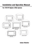
Operation Manual
For TCP/IP with VYROX V90 / V91 system
Indoor Monitor
Remark
Please follow the user manual for correct installation and testing, if
there is any doubt please call our tech-supporting and customer
center.
Our company applies ourselves to reformation and innovation of
our products. No extra informing for any change. The illustration
shown here only used for reference, if there is any difference
please take the actual product as standard product.
CATALOG
Product Features......................................................1
Technology Parameters ...........................................1
Product Pictures ......................................................2
Operations................................................................4
1. VOIP ......................................................................5
2. Security...............................................................12
3. VHome / iSmart .............16
4. VHome PRO / iCloud ..........................................20
5. About V90/V91 ....................................................21
Web Settings ..........................................................22
System Configuration ............................................25
System Diagram .....................................................26
Installation ..............................................................28
Troubleshooting .....................................................30
Safety Precaution...................................................31
Product Features
1. Building intercom application:
VOIP: support video call, monitor and VOIP communication
Security: support 8-way zone alarm with 3 states, make the zone and
scene setup.
VHome / iSmart: support 485-way smart home extension.
VHome PRO / iCloud: support community information and website.
Contacts: support android address book.
2. Operating system: Android 4.2.2.
Technology Parameters
Voltage: DC 12V
Rated power: 6W
Standby power consumption: 1.5W
Display screen: 7'' / 10.2''
Resolution: 800*480/ 1024*600
Operating temperature: -10℃~+50℃
Relative huminity: 20%~85%
CPU: single-core 1GHz
multi-core 1GHz
Memory: DDR3 512MB (single-core)
DDR3 1GB (multi-core)
Flash: 4GB
Max TF card capacity: 32GB
-1-
Pictures
Model:S1 (Apply for V91 system)
Power
Volume
Return
Speaker
Camera
TF card slot
USB interface
Microphone
Display screen
Model:S2 (Apply for V90/V91 system)
Power
Return
Speaker
Camera
TF card slot
USB interface
Display screen
Microphone
-2-
Model:S3 (Apply for V90/V91 system)
Power
Return
Speaker
Camera
TF card slot
USB interface
Model:S4 (Apply for V90/V91 system)
Power
Return
Speaker
Camera
TF card slot
USB interface
Microphone
-3-
Operations
Main interface: VOIP, Security, iSmart, iCloud, News, Contacts, Gallery, Calendar
and About V90/ V91.
Status bar: return, main interface, background program, screenshot volume-,volume+,
system setup, time, network connection and battery.
Status bar instruction:
1. Return
: click it to return to previous menu.
2. Main interface
: click it to return to main interface.
3.Background program
: Click it to display the operating program on the
background.
4. Screenshot
5. Volume-
: click it to make the screenshot (for V91 system).
: Click it to reduce the volume.
: Click it to increase the volume.
6. Volume+
7. System setup
: Click it to enter into the system setup menu.
8. Time
: set it in the system.
9. Battery
: display the battery at present.
-4-
1.VOIP
Click “VOIP” icon on the main interface, the system will enter the following
interface:
1.1 Call
Click “Call” icon, the system will enter the following interface:
1.1.1 Call unit resident
Input 1-3 digit building No.+ “Building” + 2 digit Unit No. + “Door” +4 digit
room No., then click
icon to call.
The system will enter into the following interface:
-5-
When answer the call, the system will enter into call state:
①If with a camera, the caller’s image will be displayed on the screen;
② When answer the call, the called person’s video will be uploaded into the
calling indoor monitor.
When the outdoor panel, wall panel and flat camera calls, the indoor monitor
will ring; when outdoor panel A calls user B, and user B has no answer, outdoor
panel A’s image will be displayed on the indoor monitor; if no answer within 25
seconds, the call will be ended.
Click
call; click
icon to communicate with outdoor panel A; click
icon to end the
icon to unlock the door.
Remark: visual intercom function between households is optional.
You can make audio and video recording during communication (TF card
should be inserted into indoor monitor ). Click
image; click
icon to snapshot the visitor’s
icon to save the video and image for the current communication.
1.1.2 Call management center
Click “Center” icon to call management center, the system will call from
management center 1 to 5. If cannot search the management center or call failed,
the system will auto call the next management center. When the management
center answers, it will ring and stop calling increasingly.
Click
icon to end the communication.
1.2 Monitor
Click “Monitor” icon, the system will enter the following interface:
-6-
Click “Door01” icon to switch outdoor panel and flat camera mode, then click
or
icon to select the area you want to monitor, and click
icon to monitor
the outdoor panel or flat camera. Click
icon to end the monitor. Click
icon to
unlock the door.
Remark: if exceeds 30 seconds, it will exit monitor.
1.3 Records
Click “Records” icon, the system will enter the following interface:
refers to call-out record;
refers to call-in record;
refers to missed call
record.
Click
call; click
or
icon to search records. Select one record and click
icon to delete it.
If has snapshot image, click
icon to view it.
-7-
icon to
1.4 Room
Click “Room” icon, then input 1-16 digits password (the default password is
123456 ) to enter into the following interface:
Warning: Please revise synchronous No.(6 digits) as soon as possible
after you read the user’s manual. The synchronous No. of all indoor monitors
in one household must be same.
Input the 3 digits Building No. such as 001, and then click “Next” to finish the
building No. setting.
The setting of Unit No.,Floor No, Room No., Device No., and Synchronous No.
is the same as Building No. setting. The Unit No., Floor No., and Room No. is
limited 2 digits respectively. When Device No. is set to be 0, we regard the indoor
monitor as the main; when Device No. is set from 1 to 5, we regard it as the sub1 to
sub5.
Click
icon on top right corner to make network setup, the system will enter
into the following interface:
-8-
Wi-Fi function is reserved.
Click “More” icon to enter into the following interface:
Click “Ethernet” icon to enter into the following interface:
Click “Advanced Configure” icon to enter into the following interface:
IP address is unique.
The default Mask address is 255.255.255.0. Normally, it is unnecessary to modify
-9-
If you would like to modify , click the setting box twice, it will popup a
keypad.
Enter your new Mask address.
The Gateway in one system must be in the same segment.
DNS: domain name resolution address (DNS of local operator). If the indoor
monitor is used in outgoing network, the address must be completed correctly; if it
is used in internal network, the address can be ignored.)
MAC Address: system default setting, without any change.
Click “OK” to save the setting.
Remark: the setting should be made after inputting password to enter into
room No. setting.
1.5 VOIP
Click “VOIP” icon, the system will enter the following interface:
Proxy: sip proxy server URL, the form is sip:ip or sip: realm name.
Realm: the scope for the device, is the same with IP or realm name.
Password: the password switched in proxy server, offered by the administrator of sip
proxy server.
Stun IP and port: the public network server IP and port crossed by audio/video NAT.
If want to connect with SIP phone, check “Enable” and input the registered
SIP account.
-10-
1.6 Settings
Click “Settings” icon, the system will enter the following interface:
1.6.1 Intercom
Check “Camera” , “Message” or “Auto answer” to enable corresponding
function, then click “OK” icon.
1.6.2 Password
Click “Password” icon to enter into the following interface:
You can set the new system password with 1-16 digits (the default password is
123456). System password is used for system settings.
-11-
1.6.3 QR Code
Click “QR Code” icon to enter into the following interface:
Scan the QR code with our mobile client software, it will be synchronized with
the indoor monitor.
2.Security
Click “Security” icon on the main interface, the system will enter into the
following interface:
2.1 ON/OFF
Click “ON/OFF” icon, the system will enter the following interface:
-12-
2.1.1 ON
Click “Out” “Home”, or “Sleep” icon to active the alarm sensors, the icon
on the main interface will light with a “Di-Di” tone and this icon will always light up.
2.1.2 OFF
(1) During the alarm delay time, Click “OFF” icon , the system will sound a
tone, then the alarm is stopped.
(2) Input user password(the default password is 1234) to stop the alarm under
alarm ON status.
2.2 Zone
Remark: the setting should be made when alarm OFF.
Click “Zone” icon, input 1-16 digits password(the default password is 1234),
the system will enter into the following interface:
-13-
2.2.1 Alarm Type
Click type input box, it will popup a dialog box
as the following. In this
interface, you can set alarm Type as: Normal, Emergency and 24H. 24H and
Emergency type are always active.
2.2.2 Delay Time
It refers to the delay time of giving an alarm. Click Delay setting box, it will
popup a dialog box as the following interface with followings: 0s, 5s, 15s, 20s, 25s,
40s and 60s, and choose the desired delay section. For example, you select the
delay time: 5S. Once the alarm sensor is triggered, 5 seconds later, the indoor
monitor will sound sirens.
2.2.3 Sensor Type
Click sensor type input box, it will popup a dialog box such as the following
interface. Each sensor type can be set up as: Smoke, Gas, PIR, Door, Window,
Panic, Flood, Pull Cord and Bed Mat.
-14-
When alarm sensor is triggered, the indoor monitor will make a loud alarm
sound, the system will enter into the following interface, and send alarm message
to management center (if your system installed management center):
You can see the No. and sensor type in red color showed at the top of
interface. For example: “2:Smoke” to indicate that Zone 2, Smoke sensor are
triggered.
To stop the alarm sound, input the password (the default password is 1234).
2.3 Scene
Click “Scene” icon, the system will enter into the following interface:
-15-
is refer to Alarm ON,
is refer to Alarm OFF. To set the sensor of alarm
stations, you can click the corresponding station with
icon.
2.4 Settings
Click “Settings” icon, the system will enter into the following interface:
You can set the new user password with 1-16 digits (the default password is
1234). User password is used for security.
3.iSmart
Click “iSmart” icon on the main interface, the system will enter into the
following interface:
-16-
3.1 Scene
Click “Scene” icon, the system will enter into the following interface:
Scene mode includes: Home, Out , Movie, Party, and sleep.
3.2 Light
Click “Light” icon, the system will enter into the following interface:
-17-
Set the light of corresponding room, such as Master, Sub, Living and Dining
(see the room setting for details),8 lights can be set in every room at most. Click
the corresponding light icon, then you can control the light turn ON/OFF.
3.3 Air
Click “Air” icon, the system will enter into the following interface:
Set the air-condition switch of corresponding room. Click “OFF” icon to turn
air-condition on/off; click “Cold” icon to cool; click “Wet” icon to dehumidify; click
“Wind” icon to ventilate.
2 air-conditions can be set every room at most.
3.4 Curtain
Click “Curtain” icon, the system will enter into the following interface:
Click “Close” icon, the curtain is closed; if click “Open” icon, the curtain is
open; if click “Pause” icon, the curtain is paused.
-18-
3.5 Elevator
Click “Elevator” icon, the system will enter into the following interface:
Click
or
icon to control the elevator to up and down. Click “Permit” icon
to open the floor that the indoor monitor locates.
Remark: To support this interface, your system must connect with “Elevator
Control” module. Kindly check with your system provider.
3.6 Settings
Click “Settings” icon, the system will enter into the following interface:
3.6.1 Room setting
You can add, delete room data and change the room type. The room types
includes: Living, Dining, Master, Sub, Study, Kitchen and corridor.
There are max. 20 rooms you can set.
3.6.2 Light setting
Click “LIGHT” icon, the system will enter into the following interface:
-19-
There are max. 8 routes light for each room. You can set the corresponding
room’s lamp. Choose the room type firstly, then you can set the name for each light.
4.iCloud
Click “iCloud” icon on the main interface, the system will enter into the
following interface:
BROWSER
4.1 SMS
Click “SMS” icon, the system will enter into the following interface:
-20-
Note: only install the management software on PC which usually locate at
guard center, the indoor monitor can receive the message sent by PC.
Click
icon to page up; click
icon to page down; click
icon to delete
the record.
64 records can be received in SMS at most.
4.2 BROWSER
Click “BROWSER” icon, the system will enter into the web page linked with the
indoor monitor (the function should be supported by outer network).
“COOK”, “MAP”, “GOV” and “MALL” is reserved.
5.About V90/V91
Click “About V90/V91” icon on the main interface, the system will enter into the
following interface:
You can look over the relevant information.
-21-
Web Settings
Click VOIP->Room->Password:123456->Click the icon at the top right corner>More->Ethernet->Advanced Configure (Don't check “DHCP”) to view IP address.
Connect the indoor monitor and computer by network switch. Input the indoor
monitor’s IP address in the browser, then input user name and password (the
default user name is “admin”, the password is “123456" to enter into the web
setting interface.
1. VOIP
Click “VOIP”icon to enter into the following interface:
The setting is same with indoor monitor’s.
If want to connect with SIP phone, check “SIP Enable”, and input the
number registered in SIP server.
Timeout: choose the longest communication time.
Click “Submit” icon to save the setting.
-22-
2. Advanced
Click “Advanced”icon to enter into the following interface:
Ex Phone: input IP address of other manufacturer’s SIP device. It refers to
used other factory’s VOIP device as sub indoor monitor of our indoor monitor.
When outdoor panel calls indoor monitor, VOIP will ring at the same time, and other
terminals will stop ringing when one of the indoor monitor or VOIP is answered.
Auto Pickup: check the frame, the indoor monitor will auto answer when
outdoor panel calls it and no answer within 10s.
Quick Call: Input SIP address of the specified management center, it can be
indoor monitor, also be other IP phone, the format can be like this: sip:user name@
SIP server IP address. When click “center” icon, it will be transferred to the binding
equipment.
Remark: the address can be the SIP address of indoor monitor or other
factory’s VOIP device.
Click“Submit” icon to save the setting.
3. Webkit
Click “Webkit”icon to enter into the following interface:
-23-
Advertising: used web page as the image. Check the frame, it will display
when the indoor monitor is on standby state.
Browser: input the linking address in the frame, and there is a “BROWSER” icon
on the indoor monitor, when the user click the icon ,it will switch into the linking web
page.
4. License
It is reserved.
5. Logout
Click “Logout”icon to enter into the following interface:
Click “submit”icon, it will logout the system.
-24-
System Configuration
CAT-5e+RVV2
*1.0
Terminal
Power
220V
Terminal
Power
220V
Network Switch
Network Switch
2F
2F
CAT-5e
CAT-5e
Terminal
Power
CAT-5e+RVV2
*1.0
220V
Terminal
Power
RVV2*1.0
1F
220V
RVV2*1.0
1F
Fiber Optical
Transceiver
Network Switch
Fiber Optical
Transceiver
Network Switch
RVV3*1.0
RVV3*1.0
Power
Power
220V
220V
RVV2*1.0
Outdoor Panel
RVV2*1.0
Outdoor Panel
Electric
Lock
Electric
Lock
Villa District
Four-core single mode fiber
CAT-5e+RVV2*1.0
Flat
Camera
Terminal
Power
CAT-5e
220V
Indoor equipment
box
RVV2*1.0
CAT-5e+RVV2*1.0
Network Switch
Terminal
Power
Electric
Lock
RVV2*1.0
Fiber Optical
Transceiver
Fiber Optical
Transceiver
Fiber Optical
Transceiver
Fiber Optical
Transceiver
CAT 5e+RVV2*1.0
Flat
Camera
Four-core single
mode fiber
CAT-5e+RVV2
*1.0
Electric
Lock
Four-core single
mode fiber
Four-core single mode fiber
Network
Switch
Fiber Optical
Transceiver
CAT-5e
(National Standard)
Outdoor equipment
box
220V
220V
CAT 5e
Indoor equipment
box
CAT-5e
Fiber Optical
Transceiver
Power
CAT-5e
Management Center
Power
220V
220V
CAT 5e
RVV2*1.0
RVV3*1.0
RVV2*1.0
Electric
Lock
PC
RVV2*0.5
Exit Button
Wall Panel
-25-
Management Center
System
System
Configuration
Diagram
RJ45
Power DC12V
12345678
RS485
Siren
3
4
+12V
GND
485+
485
1
2
3
4
5
+12V
GND
AL1
AL2
AL3
1
2
GND
2
V+
1
Alarm
8
AL4
AL5
AL6
9 10
AL8
7
AL7
6
1.Power
Power input interface, connect with 12V power adapter.
DC 12V
2.RS485
Connect with smart home, alarm extern module. etc.
Offer a group of 12V/100mA power by RS485.
+12V
GND
485+
485
+12V
GND
485+
485
RS485 Interface
RS485 Equipment
-26-
3.Alarm interface
8-way zone alarm interface with 3 states, connect with normally-open
or normally-closed switch.
Offer a group of 12V/100mA power by alarm interface.
+12V
GND
AL1
AL2
AL3
AL4
AL5
AL6
AL7
AL8
2.2K
Normally-open sensor
Alarm
Normally-closed sensor
4.RJ45
Connect with outdoor panel, indoor monitor or other network equipment
by network switch.
CAT-5e
RJ45
5.Siren
When alarm sensor is triggered, output 12V/mA power.
V+
GND
Siren
Alarm facility
-27-
System
Configuration
Installation
Model: S1
Built-in box
Screws
Size: 261.7*175.3*15mm
Model: S2
Built-in box
Screws
Size: 205*126*15mm
-28-
Model: S3
Built-in box
Screws
Size: 270*168*15mm
Model: S4
Built-in box
Screws
Size: 205*129*15mm
-29-
Troubleshooting
The indoor monitor cannot start up or auto power off.
Check whether it has power-failure, power on it again.
Theindoormonitordisplayscreenistoodim.
Check whether the brightness and contrast settings of screen are
correct.
Nosoundduringthecommunication.
Check whether the indoor monitor is set as mute mode, or the volume is
adjusted at the minium.
The indoor monitor cannot monitor the outdoor panel.
Other users is using the system, when he finished the use, you
can use it normally.
Multimedia files cannot be played normally
Check whether the system supports the file format, please refer to
multimedia setting for details.
No response when clicking indoor monitor display screen.
Press “Unlock” button for 5s, or slowly sliding along horizontal or vertical
on the LCD to make touchscreen calibnation, need to calibrate twice.
Touchscreen responses slowly or cannot make calibnation
Take down any protective paster, it may affect identification and
input for device;
Ensure the finger is dry and clean when clicking touchscreen;
Restart the device to clear any temporary software error.
The temperature of device is too high.
Long use leads to high temperature, this is normal, it will not affect the
device’s use life and performance.
-30-
Safety Precaution
In order to prevent you and others from injury, or
prevent your device from damage, please use the device
after reading the following information.
Don't install the device in the following places:
Don’t install the device on the place with high temperature, moisture, and
near magnetic field, such as the place near generator, transformer or magnet.
Don't place the device near electric heater. etc heat source,or the container
filled with liquid.
Don’t place the device under the sunshine or near the heat source, it may
lead to decoloration or transformation of device.
Don’t install the device on the rocking and vibrant place to avoid the device’s
falling to cause property loss or personnel injury.
Prevent electric shock, fire and explosion.
Don't use damaged power line, plug or loosen outlet
Don’t touch the power line with wet hand, or pull the power line.
Don’t buckle or damage the power line.
Don’t touch the device with wet hand.
Don’t make the power supply fell, or make collision for the device.
Don’t use the power supply without manufacturer’s approval.
Don’t splash water.etc liquid into the device.
Clear the screen.
Clear finger print, dust.etc on the display screen gently with soft cloth.
Clear the device surface.
Clear the device surface with soft cloth dipped in some water, then wipe the
surface dry.
-31-
Other notes
In order to prevent paintcoat or outer skin from damage, don’t make the device
contact with chemicals, such as diluent, gasoline, alcohol, insect-resist agents,
opacifier, insecticide. etc.
Don’t knock or beat the device with hard materials.
Don’t put pressure on display screen, too hard to lead to frame stoppage or
damage for the device.
If sit under the device, please pay more attention when stand up.
Don’t disassemble, configure or fix the device by oneself, the manufacturer
will not guarantee for any change or configuration of device. If need to repair,
please contact with customer service center.
If the device makes strange sound, taste or smoke, please unplug the power
supply immediately, and contact with customer service center in time.
If not use the device for long time, suggest to unplug the power adapter and
SD card, and place it on the dry environment.
Please turn the instruction into the new household, ensure he/she to use the
device correctly.
-32-