1
ELD USER MANUAL ISSUE 1
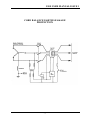
test resistor to earth method is recommended
with this type of protection as this test also
proves the neutral to earth connection.
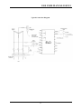
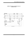
See typical circuit, Page 8.
2. Do not bring the cables back past the
toroid within one diameter of the toroid.
Trying to cram cables into a small space
reduces symmetry and may lead to
problems, which are difficult to solve.
2.5 Earth Leakage Toroids
Toroids (current transformers) are not ideal
devices and if correct procedures are not
followed during installation nuisance tripping
can result. If, for example, we consider a
single-phase earth leakage system where active
and neutral pass through a toroid then at all
times currents in the two wires are equal and
opposite so that the net current through the
toroid is zero. An ideal current transformer
would have all of the flux from each wire
contained in the core and so would accurately
add the opposing fluxes to get a net result of
zero. A real current transformer has “leakage
fluxes”. That is, a very small proportion of the
total flux from each cable is not contained in
the core but in the space outside it and as a
result it may link some turns but not others,
depending on the positioning of the cables. The
effect of this is that a small output may be
obtained from the toroid where none would
arise if the device were ideal.
3. Avoid placing the toroid near any device,
which produces magnetic fields. This
includes bus bars, transformers or other
cables. Try to maintain several toroid
diameters clearance.
4. Many small cables tend to be worse than
say three large ones. Try to position the
toroid in the circuit with this in mind.
5. Toroids used for core balance earth
leakage protection cannot have bus bars
passed through the toroid.
To prevent possible nuisance tripping it is
suggested that the conductor screen of the
earth leakage toroid should be earthed one end
only, the relay end. If both ends are earthed the
possibility exists for the shield to become an
earth loop, having finite resistance and
injecting noise into the toroid leads.
The size of the error may vary from toroids of
the same type because of slight differences in
the core and the symmetry of the winding.
Problems caused in this way increase as the
toroid size increases, as currents increase and
symmetry decreases. Nuisance tripping tends
to occur when the total current rises, such as
when a large motor is started. The following
guidelines would help to avoid such problems.
2.6 Toroid Selection
1. Select the smallest internal diameter
toroid, which will allow the cables to fit
through. Avoid very large toroids
(200mm) or toroids with square apertures.
2. Only use approved toroids specified by
Ampcontrol as these have been designed to
minimise the problem.
2.7 Toroid Installation Guidelines
1. Keep cables as close to the centre of the
toroid as possible. Do not tie them to one
side of the toroid. Remember to aim at
symmetry
-3-