1
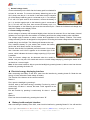
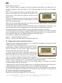
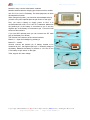
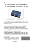
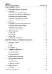
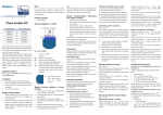
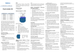
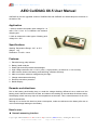
Aero Electronics Operations http://www.aeo rc.com AEO CellDIAG X6.5 User Manual CellDIAG X6.5 is the upgraded version of CellDIAG X6 and CellDIAG X4. We develop new functions on the basis of X6. Application 1. Able to measure the battery pack voltage for 1-6 cells Li-Po/ Li-Ion/ Li-Fe batteries with balance charging port. 2. Able to measure the other types of battery pack voltage for 1-25V Specifications Working Temperature Range: -20℃ to 50℃ Weight: 21g Dimension: 33 x 69 x 11mm Features: 1.Electrical energy strip indicator 2.Battery health analysis 3.Small, light and ultra-portable with backlight. 4.High voltage resolution with +/-0.01V (10mv) ; High precision, not less than +/-2% accuracy. 5.Able to direct observe the battery pack balancing condition efficiently. 6.Able to record the minimum voltage during the flight. 7.Voltage measurement trimming. 8.Reverse connection protection 9.Backlit Display Remarks and attentions: Due to the battery pack loading drop, to avoid the voltage checking difference/ error, make sure the battery pack is disconnected from the load, and observe the reading 30 seconds later the disconnection. Data display refresh rate may drops in low temperature environment. This is normal because of the LCD panel characteristics. Although it is a device with ultra low power consumption, make sure disconnect the battery after use to void over discharge/ damage to the battery. How to use: Normal measuring interface Copy right 2005-2008 A ero E le ctron ics O p e rat io n s (AEO Tec h), A ll R ig hts Res e rve d http://www.aeoRC.com h ttp://www.aeoRC.cn Aero Electronics Operations http://www.aeo rc.com 1.Normal voltage check. Connect the battery to the X6.5 after the battery pack is unloaded for at least 30 seconds. To connect the battery balancing port to the X6.5, always use the pin 1 on the X6.5, and make sure the negative pin of the battery balancing port is connected to pin 1. For example, if a 3 cell Li-Po pack need to be measured, connect the battery to pin 1~4, and the negative pin on the balancing port is connected to pin 1; if it is a 5 cell Li-Po pack, then connect the battery to pin 1~6, and the negative on the balancing port must be connected to pin 1. Read the individual cell voltage and total pack voltage on the display screen. 2. Lowest voltage recording As the voltage of a battery will increased slightly when the load is removed. Due to the battery internal resistant, we can’t figure out the condition of a battery pack from the voltage reading when unloaded. The voltage might increases to about a same level regardless of the battery condition. The lowest voltage recording function is designed for the purpose of recording the lowest voltage when the battery is loaded though out the flight. The following will introduce the way. First, install the battery on your model, and connect the battery pack to the X6.5. Mount the X6.5 on the plane. Second, After the X6.5 is initialized, press the button A for not less than 1seconds until “HOLD” appears on the bottom-right of the screen, which indicates the lowest voltage capturing (LVC) model is enabled. Third, the lowest voltage can be observed when the model is landed. And you may exit LVC model and return to normal voltage display by pressing the button A for not less than 1 second again. Note: At the current interface, able to open the backlight by pressing button A; able to enter into the next interface by pressing the button “B” Electrical energy displaying interface After connecting the battery to the X6.5, enter into this interface by pressing button B. Read the rest energy of each cell and the total voltage of battery. The function of the buttons at the current interface: Button A First, open the backlight by pressing it Second, start up the lowest energy recording Function by press it continuously for about 1 second, the letter “Hold” appears on the bottom right. Exit this function by pressing it continuously for about 1 second again. Button B Enter into the next interface by pressing the button “B”. Battery health analysis interface. After connecting the battery to the X6.5, enter into this interface by pressing Button B. You will read the Copy right 2005-2008 A ero E le ctron ics O p e rat io n s (AEO Tec h), A ll R ig hts Res e rve d http://www.aeoRC.com h ttp://www.aeoRC.cn Aero Electronics Operations http://www.aeo rc.com following data on the screen MAX***: the Max voltage, the voltage of a cell that the voltage is the highest in the battery pack. For example, the display on the screen: MAX U3: 3.79V means the voltage on the Fourth pin is the highest of 3.79V. MIN***: the Min voltage, the voltage of a cell that the voltage is the highest in the battery pack. For example, the display on the screen: MIN U1:3.54V means the voltage on the first pin is the lowest of 3.54V. HEALTH***: the battery pack index. Read the index after charging completely, if the index is lower than a certain degree, you should check if the charger is all right. Read the index after discharging with load, if the index is lower than a certain degree, you should check if the cell with the lowest voltage is damaged. Generally, if the index is lower than 90, you should note a cell in the battery pack; if lower than 70, the cell in the battery pack may be damaged and you should replace it to avoid affecting other cells. The display bar below the letter “ENERGY” show the rest energy percentage of the battery. As the characteristics of the battery, we suggest charging before every flight. Don’t fly the model again even if the battery still has 80% energy, especially for the large power load, such as a helicopter model. For the long time usage, don’t use it again if the battery has only 60% energy. The function of the buttons at the current interface: Button A --- Open the backlight by pressing it Button B --- Enter into the next interface by pressing the button “B”. Voltage measurement trimming interface: Voltage drift can be happened after long time of use, so adjustment of voltage is very important to keep the good accuracy of voltage measurement. 1. Press both A, B button simultaneously, and connect the X6.5 with the battery. Continue to hold the two buttons for 1 second after the connection. The X6.5 enters voltage measurement trimming mode (VMT) as per shown on the right 2. You can use the two bottoms to adjust the reading of the highlighted voltage value for each of the battery cells. Pressing the A to increase the value, and press the B to decrease the value. For example the displayed in the above figure is adjusting voltage of the first cell, which is connected to pin 1 and pin 2. You may press the A to increase 34165 (means 3.4165V) to 34166 and so on, or press the B to decrease 34165 to 34164. 3. Press A and B simultaneously to jump to the next voltage reading of the battery cell, which is connected between pin 2 and 3 in this case. 4. Repeat the step 2 and 3 until all cell voltages is done. It is suggested to adjust the value according to a voltage measuring instrument to minimize the error, such as a good quality multi-meter. It is recommended to apply 6 cell battery pack to perform the VMT, so that all readings can be adjusted. If using a lower than 6S battery, there will be a 0.3% inaccuracy. It’s the normal case, no influence to use Series connection measuring interface Although most of the power supplies use Li-Po/ Li-Ion/ Li-Fe Copy right 2005-2008 A ero E le ctron ics O p e rat io n s (AEO Tec h), A ll R ig hts Res e rve d http://www.aeoRC.com h ttp://www.aeoRC.cn Aero Electronics Operations http://www.aeo rc.com batteries, many use the nickel-metal, cadmium batteries without balance charging port and most micro models use 1S Li-Po/ Li-Ion/ Li-Fe battery. For these purposes, we have developed this function. When using this function, you should do some adapter wire by yourself or buy AEO optional parts as per shown on the right. First, you need a battery to supply power to X6.5. It is recommended 2S or 3S Li-Po/ Li-Ion/ Li-Fe batteries. Make sure the positive pin of the battery is connected to pin 3 and the negative pin of the battery is connected to pin 1. Now X6.5 will enter into this interface. If you use AEO optional parts you can connect the JST male plug of the battery to it directly. The function of the buttons at the current interface Button A --- Open the backlight by pressing it Button B --- Invalid Second, connect the positive pin of battery needed to be measured to pin 7, the negative pin to pin 1. Read the voltage of the battery. Measure the battery of receiver or 1S Li-Po/ Li-Ion/ Li-Fe battery as per shown on the right. Third, support 25V max voltage. Copy right 2005-2008 A ero E le ctron ics O p e rat io n s (AEO Tec h), A ll R ig hts Res e rve d http://www.aeoRC.com h ttp://www.aeoRC.cn