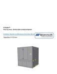
1
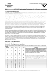
Modeling Direct Expansion (DX) Systems in TRACE™700
Trane C.D.S. eLearning Library
Slide 1 TRACE™ 700
Modeling
Direct Expansion (DX) Systems
Slide 2 Modeling DX Systems in TRACE
• What are DX systems?
• Important inputs
•
•
Create Systems
Create Plants
• What reports should be used for sizing?
Slide 3 What are DX systems?
©2015 Trane a business of Ingersoll Rand
All rights reserved.
Hello, my name is Caitlin Bohnert and I’m a marketing engineer in the C.D.S. group at TRANE. In this video, we will take a look at modeling DX, or direct expansion, systems in TRACE 700. To do this, I will focus on packaged RTU and typical split systems and then answer several questions related to DX systems including what they are and any associated assumptions made within the program. We will take a look at specific inputs for this type of equipment – both in Create Systems and Create Plants. I will then walk through some examples. Finally I’ll discuss the best reports to reference to size your DX equipment. So what are DX systems? DX systems provide cooling to the airstream without the use of chilled water. The air passes directly through the evaporator of the refrigerant loop which is where the “direct” portion of the name is derived. The “expansion” portion of the name comes from the fact that the refrigerant passes through an expansion device prior to entering the coil then expands from a liquid to a vapor as the refrigerant passes through the coil and absorbs heat from the air. There are two different physical configurations for DX pieces of equipment, the packaged system and the split system. Packaged systems house the cooling coil, compressor, and condenser all in the same unit. Split systems on the other hand locate some components outside and others inside the building. A typical split DX system locates the cooling coil Modeling Direct Expansion (DX) Systems in TRACE™700
Trane C.D.S. eLearning Library
inside the building in an air handling unit while the compressor and condenser are located outside with refrigerant lines connecting the outside and inside components. An advantage of packaged systems is that the refrigerant lines can be shorter and the entire system can be factory tested. The advantage of split systems is that the ductwork can be shorter because the cooling coil is located closer to the conditioned space. Typically DX systems are less expensive and generally easier to install than chilled water systems. They are also useful for tenant buildings because small, separate DX systems can be installed in each tenant space where each tenant will pay separately for their own energy consumption. Slide 4 Examples of DX systems
•
•
•
•
•
•
•
Mini-splits
Split DX systems
Variable refrigerant flow (VRF)
Water-source heat pumps (WSHP)
Packaged terminal air conditioners (PTAC)
Packaged single- and multiple-zone rooftops
Self-contained systems (water-cooled unitary)
©2015 Trane a business of Ingersoll Rand
All rights reserved.
There are a number of airside system types that can be served by a DX cooling coil. These include variable refrigerant flow systems, water‐source heat pumps, packaged terminal air conditioners, single zone constant and variable volume rooftop units, and water cooled unitary pieces of equipment. Today we will focus on packaged units and split systems. Modeling Direct Expansion (DX) Systems in TRACE™700
Slide 5 Trane C.D.S. eLearning Library
How the airside systems set up in
TRACE?
©2015 Trane a business of Ingersoll Rand
All rights reserved.
Now that you have a basic understanding of what DX systems are, let’s take a look at how they are set up in TRACE. After the templates and rooms have been created for the project, the airside systems can be set up. It is important to note that in Create Systems, only the air path and coil and fan locations are defined. The refrigeration and heating sources are not defined until Create Plants. For this reason, there is no option for a “DX” system type listed on the Selection tab. Here, in Create Systems, you are defining the air delivery type such as: constant volume single zone, multiple zone VAV, PTAC, or water‐
source heat pump. By selecting a particular system, you are also specifying where the coil will be located ‐ whether it is at the system, zone, or room level. This will be important when you assign your rooms to your systems. A system level coil is an individual coil that serves all the zones and rooms assigned to that system. An example of this is the cooling coil of a VAV reheat system. When the coil is set to the zone level, each zone on the system will receive its own coil. An example being the reheat coils located in the terminal boxes of a VAV reheat system. Finally, when the coil level is set to room, each and every room on the system will get its own coil which is true for the water source heat pump system. You can determine the level of the coil by clicking the advanced button (click) in Create Systems and (click) looking at the (click) cooling coil location field. For more information on coil locations and zoning, check out the “Room and Zone Assignments” video on our website. I’ll show you how to access this at the end of the video. Something else to mention on this screen is the (click) Fan configuration option. Here you can designate if your fan is located before the coil as blow through or if it is located after the coil as draw through. Modeling Direct Expansion (DX) Systems in TRACE™700
Slide 6 Trane C.D.S. eLearning Library
DX System Additions
Slide 7 Slide 8 ©2015 Trane a business of Ingersoll Rand
All rights reserved.
Once you have selected your airside system, there are some additional features you can add. These are found on the Options tab of Create Systems. Here there are (click) dry bulb, wet bulb, and enthalpy economizers available as well as an exhaustive list of (click) energy recovery devices. You can hit the F1 key while on this screen and follow the blue links to see detailed descriptions of all the options. From the Options tab, you can click the Advanced Options button to access features such as the (click) optimum start schedule, and (click) supply air temperature reset which may be required for LEED models depending on your system type and size. If you wish to account for pressure losses in the duct, you will need to input a fan type and static pressure for all your fans, on the fans tab of Create Systems. If you are assigning multiple fans and coils to one system, the static pressure is an average, and the full load energy rate is the total full load rate for all the fans. Modeling Direct Expansion (DX) Systems in TRACE™700
Slide 9 Trane C.D.S. eLearning Library
Elements that are not inputs in TRACE
• Whether the system is packaged or split
• Refrigerant pipe lengths
• Air duct lengths
Slide 10 How to configure your plants
• Air-cooled unitary
• Water-cooled unitary
• Water source heat
pump
• Air-cooled chiller
• Water-cooled chiller
©2015 Trane a business of Ingersoll Rand
All rights reserved.
Here I’d like to take a moment to make you aware of some important design considerations that TRACE does not take into account. TRACE is not spatially aware so it doesn’t know whether the DX system you are modeling is a packaged unit or a split system. This has an impact on two key design elements. First, TRACE does not consider the length of refrigerant piping for the unit. This is especially important for split systems that have longer refrigerant piping runs connecting the indoor evaporator to the outdoor compressor and condenser. Longer pipe lengths can have a negative impact on maintaining refrigerant temperature and phase as it travels between components. There are also building code requirements that must be met regarding the maximum refrigerant pipe lengths. This design work will need to be conducted outside of TRACE. Second, TRACE does not consider the length of air ducts and how far the air must travel from the cooling coil to the conditioned space. This is more important with packaged systems where the unit is generally located on the roof and may serve several floors using long sections of ductwork. Once your systems are configured, you can set up your plants which will dictate the type of energy your coils will use to condition the air. Let’s take a look at cooling equipment first. TRACE has five different plant categories for cooling equipment, three of which can be used to model DX equipment. These are the air cooled unitary, water cooled unitary, and water source heat pump. The air cooled chiller and water cooled chiller are not to be used for DX systems. Remember, “Plants” is somewhat of a misnomer for DX equipment, so its configuration must be viewed a little differently when assigning coils and equipment to a plant. Modeling Direct Expansion (DX) Systems in TRACE™700
Trane C.D.S. eLearning Library
Slide 11 ©2015 Trane a business of Ingersoll Rand
All rights reserved.
When creating plants for DX equipment, we can essentially create a cooling plant for every RTU. The maximum number of cooling and heating plants allowed in TRACE, however, is 20. If you require more than 20 plants, you can group airside systems that are similar in RTU performance and put them on a single cooling plant with a single, larger piece of equipment with a weighted average for efficiency. Remember, do not put multiple pieces of DX equipment under one plant unless you are planning on sequencing them which is NOT typical. After you have chosen the proper equipment category, you will need to choose the specific piece of equipment you wish to model in the Equipment Type dropdown (click). This input will be somewhat dependent upon what was chosen in Create Systems. For example, if you are modeling a packaged terminal air conditioner, you should select one of the PTAC options from the dropdown. Likewise, if you are modeling a single zone VAV rooftop unit, you should select one of the rooftop unit options in the dropdown. You can choose to enter a cooling capacity (click) if you already have a specific piece of equipment chosen or you can leave it blank and TRACE will determine the size for you. Note, for heat pumps, the capacity in heating mode is entered in the (click) heat recovery input. This value is typically higher than the cooling capacity as we are now accounting for the capacity of the compressor plus the heat of compression. Next, you should be sure to input a value for the (click) energy rate. Something to note, here is that EER is an available unit for energy rate but IEER and SEER (also called “sear”) cannot be used. EER is the energy efficiency ratio at a given individual, design operating point. The “sear” (seasonal energy efficiency ratio) and IEER (integrated energy efficiency ratio) on the other hand are determined using both design conditions and part load conditions. This is not a valid input in TRACE because TRACE uses the ambient relief unloading curve to account for the changing outdoor temperature throughout the year. If you would like more information on the unloading curves in TRACE, please watch Modeling Direct Expansion (DX) Systems in TRACE™700
Trane C.D.S. eLearning Library
the “Creating General Equipment Performance Curves” video on our website. You can however input an energy rate as a packaged EER or packaged COP where you can decide which components of the unit are not included in the energy rate such as the supply or condenser fan for example. Slide 12 120 ton Packaged Rooftop with condenser and supply fans 10 Packaged EER
37.28 kW total design fan energy (from Equipment Energy Consumption Report) which is based on the fans input in Create Systems.
Convert 37.28 kW into kW/ton…
37.28 / 120 = 0.3107 kW/ton
Next, convert 10 EER into kW/ton…
EER = 12 / kW/ton 12 / 10 = 1.2 kW/ton
Subtract out fan energy from the packaged energy…
1.2 – 0.3107 = 0.8893 kW/ton
Last, we need to subtract out the condenser energy. The condenser fan energy is associated with the heat rejection type chosen. In this case, the condenser energy is 0.084 kW/ton (you can find this value in the Heat Rejection library).
Subtract this value from our energy rate thus far…
0.8893 – 0.084 = 0.8053 kW/ton
This value ends up being the calculated kw/ton for the compressor.
©2015 Trane a business of Ingersoll Rand
All rights reserved.
While TRACE does these calculations for you, it is useful to see what is happening in the background of the program in order to understand the Packaged EER. Say we have a 120 ton packaged RTU with both condenser and supply fans. The manufacturer states that the unit has a packaged EER of 10. Now, the total supply fan energy is equal to 37.28 kW. This can be found on the Equipment Energy Consumption report and comes from the fan inputs in Create Systems. First, you will need to convert the fan energy into a kW/ton value by taking the fan kW and dividing it by the unit tonnage. Next, the 10 EER needs to be converted to kW/ton. The fan energy is then subtracted from the total packaged energy. Finally the condenser fan energy also needs to be subtracted. Here, the condenser energy is 0.084 kW/ton which is found in the Heat Rejection library. What is left over is the kW/ton for the compressor. Additionally, if you are using a heat pump, make sure you check the box for “apply same fans for heat recovery breakout” so the packaged value is used for heating mode as well. If you look at the full load rate in the Equipment Energy Consumption report, it will show the compressor value after subtracting out the additional fan energy. The original full load rate is the packaged EER value converted to kW. Modeling Direct Expansion (DX) Systems in TRACE™700
Trane C.D.S. eLearning Library
Slide 13 ©2015 Trane a business of Ingersoll Rand
All rights reserved.
Here, I would like to briefly point out what to do if your unit has condenser evaporative precooling. Evaporative precooling is used to increase the effectiveness of air cooled pieces of equipment by precooling the condenser air before it passes through the condenser. Water evaporates from the precooling material, decreasing the entering outdoor air temperature to the condenser, which increases the condenser capacity and efficiency. This can be turned on by clicking the controls button on the cooling equipment tab of create plants and changing the (click) evaporative precooling option from No to Yes. Here you can also add hot gas reheat for dehumidification. This feature is only available for air cooled unitary, water cooled unitary, and water source heat pump pieces of equipment. It is also only for systems that already have a reheat coil for dehumidification purposes. Changing this setting (click) to Yes allows the refrigerant vapor to reject some of its heat to the over cooled air in the reheat coil thereby saving energy. If you select “yes” for this input, you need to go back to the cooling equipment screen and make sure the reject condenser heat is selected to heating plant and choose the heating plant with the appropriate heating coil. Typically hot gas reheat is used for reheat when applying dehumidification control strategies but there are plenty of applications. Modeling Direct Expansion (DX) Systems in TRACE™700
Trane C.D.S. eLearning Library
Slide 14 Slide 15 Examples
• Standard DX RTU
• Heat pump
©2015 Trane a business of Ingersoll Rand
All rights reserved.
Now that we have taken a look at the cooling equipment in detail, let’s take a look at the heating equipment. There are three categories for heating equipment: boiler, electric resistance, and gas fired heat exchanger. DX equipment refers to the cooling equipment so the type of heating equipment used is highly variable. DX rooftops and split systems commonly have gas fired heat exchangers which would be entered here on the heating equipment tab. This is also where the back‐up heat source would be entered for a heat pump system. Now let’s spend some time in the program going over some examples. We will look at two different DX systems and their configurations in Create Systems and Create Plants including a standard packaged DX system, and split system air source heat pump. Jump to TRACE wizard file We will start with the standard packaged DX rooftop example. I have already created a shopping mall using the New File Wizard utility. For more information on this utility, please see the “Using the New File Wizard in TRACE 700” video on our website. Because the templates and rooms of this project have already been created, I can proceed to the Create Systems section. Open up Create Systems This particular project uses variable volume roof top units where each wing made up of five rooms each has its own unit so I will choose the single zone variable air volume system type. Select the Variable Volume category and the Single Zone VAV system. A pop up window tells me that the coils are located at the zone level which will be important when assigning rooms to this system. Click OK to the message Modeling Direct Expansion (DX) Systems in TRACE™700
Trane C.D.S. eLearning Library
Remember, I can also determine the location of the coil by clicking the advanced button and looking at the cooling coil location field. Here we can see it is set to Zone. Click the Advanced button Click OK If you wish to specify supply air temperatures you can so do on the Temp/Humidity tab. Click Temp/Humidity tab If you leave the supply air temperatures blank, TRACE will calculate them for you. Click Fans tab Finally you will need to define your fans and their associated static pressures on the Fans tab. Be sure to define a fan and a static pressure for each of the fans in your system in order to accurately model fan energy consumption and fan motor heat pickup. I only have a primary fan in my system so I will select my fan and input my static pressure. Select “BI Centrifugal var spd mtr” (from p 9 of RT‐PRC023‐EN July 2013 for the Precedent packaged rooftop air conditioner) and 1.5 inches of static for the primary fan. That concludes the inputs for Create Systems so now we will move on to assigning our rooms to systems. Close Create Systems and open Assign Rooms to Systems. Because I want each small wing to have its own roof top unit, I will create five zones under my system and assign each wing of rooms to a zone. Assign the rooms I now have five different rooftop units and I can move on to creating my plants. Close room assignments and open Create Plants. ©2015 Trane a business of Ingersoll Rand
All rights reserved.
Modeling Direct Expansion (DX) Systems in TRACE™700
Trane C.D.S. eLearning Library
Here I will define my cooling equipment as DX equipment and set up my heating plant. Because this is an air‐cooled DX rooftop, I will drag an air‐cooled unitary piece of equipment onto my cooling plant. As described earlier, you can either create a plant for each RTU or if the RTUs are very similar in performance, create one plant and assign all coils to that particular plant. In this case, all the rooftop units are identical so I will choose only one piece of equipment to represent all 5 units. Next, these rooftop units have electric heat so I will drag an electric resistance piece of equipment onto my heating plant. I can now go to the Cooling Equipment tab to input details of this rooftop unit. I can give this piece of equipment a name in the Equipment tag field. I will call this piece of equipment “Mall RTU”. I have already chosen the Category to be Air‐cooled unitary so now I need to pick my specific piece of equipment in the Equipment type drop down. Choose the Small Rooftop – Recip Compressor I will use the default energy rate and I will leave the capacity blank so TRACE will calculate it for me. Now I will move on to the heating equipment tab where I can configure the electric resistance piece of equipment. I will leave the capacity blank here as well so TRACE can determine the necessary capacity of my heating coils. I don’t need to change any of the other inputs for this plant. I can now close out of Create Plants and assign my airside coils to the plants. You will notice here that there is only one cooling coil and one heating coil listed even though we are modeling five DX units. TRACE displays this way because the cooling and heating coils were defined under one plant with multiple zones. I will assign these coils to the plants and click close. I can now calculate the file. I am going to go over one more example before we take a look at the reports. ©2015 Trane a business of Ingersoll Rand
All rights reserved.
Modeling Direct Expansion (DX) Systems in TRACE™700
Trane C.D.S. eLearning Library
The next example is an air to air heat pump split system. I am going to start again with the same New File Wizard file. Close the current file and open the second file and go to Create Systems This time, instead of choosing a single zone system, I will choose the incremental heat pump Choose incremental heat pump from Constant Volume – Non‐mixing. Click Advanced. In the advanced window, we can see that this system has a room level coil which means each individual room will receive its own heat pump. Click on the fans tab I will again enter a fan and its associated static pressure on the fans tab of Create Systems. Select “BI Centrifugal var spd mtr” (from p 9 of RT‐PRC023‐EN July 2013 for the Precedent packaged rooftop air conditioner) and 0.5 inches of static for the primary fan. Go to assign rooms to systems Because this system has a room level coil, I can assign the rooms directly to the system and each room will receive its own coil. Assign the rooms Close room assignments and open Create Plants Here we will define our equipment in a similar manner to the standard DX rooftop piece of equipment. We again have an air‐cooled unitary piece of equipment so I will add that piece of equipment to the cooling plant. This system has electric resistance heating as the backup heat source if the heat pump runs out of capacity for heating. I can now go on to the cooling equipment. ©2015 Trane a business of Ingersoll Rand
All rights reserved.
Modeling Direct Expansion (DX) Systems in TRACE™700
Trane C.D.S. eLearning Library
I will name this piece of equipment Mall Heat Pump. Here I will choose the air‐to‐air heat pump. I’ll leave the capacity blank for TRACE to size it for me and I’ll use the default full load energy rate. You will notice this time there are values input in the heat recovery line for both capacity and energy rate. This is the capacity and energy rate for the heat pump when it is in heating mode. These are important fields because without them, the equipment will never run in heating mode and only the backup heat source will be used. Also make sure that the backup heat source is specified here. Now that the cooling equipment is set up, we will set up the backup heating plant. This heating equipment is specified as electric resistance. I will leave the capacity blank so TRACE will size it for me. Remember, this equipment will only operate when the heating load is greater than the heating capacity of the air to air heat pump or when the outdoor air dry‐bulb temperature drops below the heat pump’s minimum operating temperature, as defined in the Cooling Equipment Library. The last thing to do is to assign the coils to the plants. You will notice that while the heating mode of the air‐to‐air heat pump is specified on the cooling equipment, the heating coil should still be assigned to the heating plant. Because this heating plant is specified as the backup heat source for the air to air cooling equipment, TRACE will provide heating to this coil from the air to air heat pump first before providing heat with this backup heating plant. I can now calculate this file and we will look at the output reports. ©2015 Trane a business of Ingersoll Rand
All rights reserved.
Modeling Direct Expansion (DX) Systems in TRACE™700
Slide 16 Trane C.D.S. eLearning Library
Reports for sizing DX equipment
• Demo
©2015 Trane a business of Ingersoll Rand
All rights reserved.
There are some very useful reports in TRACE that can be used to help size equipment. The first of these are the Checksum reports. These reports provide information on: supply airflows and temperatures, cooling and heating loads, coil selections, and a breakdown of load components. It is important to make sure you are viewing the correct checksums report which is dependent upon the location of your fans and coils. If you have a zone level coil, as with our single zone VAV system, you will need to look at the Zone Checksums report to determine sizing information for coils. You can see the coil sizing information at the bottom of the report as well as supply temperatures and airflows over here. An even more useful report for equipment sizing than the checksums report is the System Component Selection report because it determines the coil level for you and reports the loads at the correct coil location. You can also use the quantities printed on this report to verify the correct number of systems and zones have been created. Here you can see that because we have 5 zones each with a zone level coil, we have 5 separate main cooling coils reported here. When we look at this same report for the air‐source heat pump system, you can see there are 25 coils because we gave every single room a coil. This report shows the peak time, total capacity, sensible capacity, required airflow, and coil entering and leaving air conditions. This report also gives sizing information for the heating coils, fans, VAV boxes, and diffusers for the system. Remember, if you are looking at coil selection, make sure you are using a coil selection software to determine the actual leaving conditions and airflow for the coil as TRACE does not know what type of coil you are using (example 4 row versus 6 row, how many fins, etc.) Modeling Direct Expansion (DX) Systems in TRACE™700
Slide 17 Trane C.D.S. eLearning Library
Additional resources
• TRACE™ 700 User’s Manual
• TRACE online (F1) help
• Other videos located at tranecds.com >
C.D.S. Help > eLearning library
Slide 18 contact us
phone I
608.787.3926
fax I
608.787.3005
email I
[email protected]
Web I
www.tranecds.com
©2015 Trane a business of Ingersoll Rand
All rights reserved.
If you would like more information on modeling DX systems in TRACE, there are a number of resources available to you. First you can use the User’s manual which is accessible from within the program by going to the Help Menu and then Documentation and then User’s Manual. This will open a searchable PDF of the entire manual. You can also use the F1 help feature within the program. If you have questions on a certain input, simply hit the F1 button on your keyboard to open up the Help file for that particular screen. The help file is full of blue links that will take you to pages with more detailed information on specific inputs. Also I referenced several other videos during this presentation. To access these videos and others, go to tranecds.com, click on C.D.S. Help, go to the eLearning tab and click on eLearning library. Finally for further assistance, if you have a valid TRACE license, you are welcome to give our support center a call or send us an email with your questions and we would be happy to help you out. Thank you for watching and have a wonderful day!