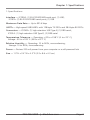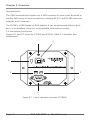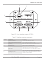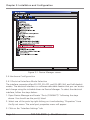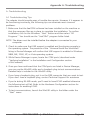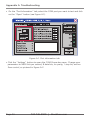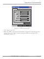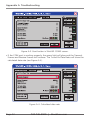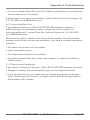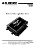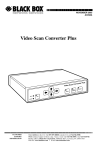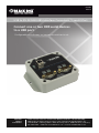
1
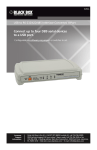
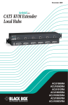
IC290A IC291A USB to RS-232/422/485 Interface Converters, 1- and 2-Port Connect one or two DB9 serial devices BLACK BOX to a USB port. ® Configurable via software; no jumpers or switches to set. Customer Support Information Order toll-free in the U.S.: Call 877-877-BBOX (outside U.S. call 724-746-5500) FREE technical support 24 hours a day, 7 days a week: Call 724-746-5500 or fax 724-746-0746 • Mailing address: Black Box Corporation, 1000 Park Drive, Lawrence, PA 15055-1018 • Web site: www.blackbox.com • E-mail: [email protected] FCC and IC RFI Statements/NOM Statement FEDERAL COMMUNICATIONS COMMISSION AND INDUSTRY CANADA RADIO FREQUENCY INTERFERENCE STATEMENTS This equipment generates, uses, and can radiate radio-frequency energy, and if not installed and used properly, that is, in strict accordance with the manufacturer’s instructions, may cause interference to radio communication. It has been tested and found to comply with the limits for a Class A computing device in accordance with the specifications in Subpart B of Part 15 of FCC rules, which are designed to provide reasonable protection against such interference when the equipment is operated in a commercial environment. Operation of this equipment in a residential area is likely to cause interference, in which case the user at his own expense will be required to take whatever measures may be necessary to correct the interference. Changes or modifications not expressly approved by the party responsible for compliance could void the user’s authority to operate the equipment. This digital apparatus does not exceed the Class A limits for radio noise emission from digital apparatus set out in the Radio Interference Regulation of Industry Canada. Le présent appareil numérique n’émet pas de bruits radioélectriques dépassant les limites applicables aux appareils numériques de la classe A prescrites dans le Règlement sur le brouillage radioélectrique publié par Industrie Canada. Normas Oficiales Mexicanas (NOM) Electrical Safety Statement INSTRUCCIONES DE SEGURIDAD 1. Todas las instrucciones de seguridad y operación deberán ser leídas antes de que el aparato eléctrico sea operado. 2. Las instrucciones de seguridad y operación deberán ser guardadas para referencia futura. 3. Todas las advertencias en el aparato eléctrico y en sus instrucciones de operación deben ser respetadas. Page 2 724-746-5500 | blackbox.com NOM Statement 4. Todas las instrucciones de operación y uso deben ser seguidas. 5. El aparato eléctrico no deberá ser usado cerca del agua—por ejemplo, cerca de la tina de baño, lavabo, sótano mojado o cerca de una alberca, etc. 6. El aparato eléctrico debe ser usado únicamente con carritos o pedestales que sean recomendados por el fabricante. 7. El aparato eléctrico debe ser montado a la pared o al techo sólo como sea recomendado por el fabricante. 8. Servicio—El usuario no debe intentar dar servicio al equipo eléctrico más allá lo descrito en las instrucciones de operación. Todo otro servicio deberá ser referido a personal de servicio calificado. 9. El aparato eléctrico debe ser situado de tal manera que su posición no interfiera su uso. La colocación del aparato eléctrico sobre una cama, sofá, alfombra o superficie similar puede bloquea la ventilación, no se debe colocar en libreros o gabinetes que impidan el flujo de aire por los orificios de ventilación. 10. El equipo eléctrico deber ser situado fuera del alcance de fuentes de calor como radiadores, registros de calor, estufas u otros aparatos (incluyendo amplificadores) que producen calor. 11. El aparato eléctrico deberá ser connectado a una fuente de poder sólo del tipo descrito en el instructivo de operación, o como se indique en el aparato. 12. Precaución debe ser tomada de tal manera que la tierra fisica y la polarización del equipo no sea eliminada. 13. Los cables de la fuente de poder deben ser guiados de tal manera que no sean pisados ni pellizcados por objetos colocados sobre o contra ellos, poniendo particular atención a los contactos y receptáculos donde salen del aparato. 14. El equipo eléctrico debe ser limpiado únicamente de acuerdo a las recomendaciones del fabricante. 15. En caso de existir, una antena externa deberá ser localizada lejos de las lineas de energia. 724-746-5500 | blackbox.com Page 3 NOM Statement 16. El cable de corriente deberá ser desconectado del cuando el equipo no sea usado por un largo periodo de tiempo. 17. Cuidado debe ser tomado de tal manera que objectos liquidos no sean derramados sobre la cubierta u orificios de ventilación. 18. Servicio por personal calificado deberá ser provisto cuando: A: El cable de poder o el contacto ha sido dañado; u B: Objectos han caído o líquido ha sido derramado dentro del aparato; o C: El aparato ha sido expuesto a la lluvia; o D: El aparato parece no operar normalmente o muestra un cambio en su desempeño; o E: El aparato ha sido tirado o su cubierta ha sido dañada. Page 4 724-746-5500 | blackbox.com Trademarks Used in this Manual Trademarks Used in this Manual Black Box and the Double Diamond logo are registered trademarks of BB Technologies, Inc. Windows and Windows Vista are registered trademarks of Microsoft Corporation. Any other trademarks mentioned in this manual are acknowledged to be the property of the trademark owners. 724-746-5500 | blackbox.com Page 5 Table of Contents Table of Contents 1. Specifications................................................................................................7 2. Overview .................................................................................................8 2.1 Introduction..........................................................................................8 2.2 Features................................................................................................8 2.3 What’s Included....................................................................................9 2.4 Optional Items You May Need.............................................................9 2.5 Hardware Description.........................................................................10 3. Installation and Configuration.....................................................................12 3.1 Software Installation...........................................................................12 3.2 Hardware Installation..........................................................................12 3.3 Verifying Installation...........................................................................13 3.4 Hardware Configuration.....................................................................14 3.4.1 Electrical Interface Mode Selection.........................................14 3.4.2 Interface Biasing......................................................................15 3.4.3 Line Termination.....................................................................16 3.4.4 Echo........................................................................................17 3.4.5 Status LEDs.............................................................................17 3.4.6 DB9M Serial Connectors.........................................................18 3.4.7 High-Retention USB Port........................................................18 Appendix A. Troubleshooting............................................................................19 A.1 Troubleshooting Tips..........................................................................19 A.2 Contacting Black Box..........................................................................23 A.3 Shipping and Packaging.....................................................................23 Appendix B. Electrical Interfaces........................................................................24 Page 6 724-746-5500 | blackbox.com Chapter 1: Specifications 1. Specifications Interface — IC290A: (1) RS-232/422/485 serial port, (1) USB; IC291A: (2) RS-232/422/485 serial ports, (1) USB Maximum Data Rate — Up to 921.6 kbps UARTs — High-speed USB/UARTs with 128-byte TX FIFOs and 384-byte RX FIFOs Connectors — IC290A: (1) high-retention USB Type B, (1) DB9 serial; IC291A: (1) high-retention USB Type B, (2) DB9 serial Temperature Tolerance — Operating: +32 to +158° F (0 to +70° C); Storage: -50 to +105° F (-58 to +221° F) Relative Humidity — Operating: 10 to 90%, noncondensing; Storage: 10 to 90%, noncondensing Power — Derives 200 mA power from your computer or a self-powered hub Size — 1.3"H x 3.4"W x 4.3"D (3.3 x 8.6 x 4.3 cm) 724-746-5500 | blackbox.com Page 7 Chapter 2: Overview 2. Overview 2.1 Introduction The USB to RS-232/422/485 Interface Converters provide an easy way to connect one or two DB9 serial device(s) to a single USB port. All configuration and electrical interface selections are handled through the driver, so you don’t have to open the enclosure to set jumpers or switches. The serial port is software configurable for RS-232, RS-422, or RS-485 (full- and half-duplex) with the electrical interface settings maintained locally, so you can repair or upgrade the host computer without reconfiguring the serial ports. The IC290A or IC291A can be configured as one computer and deployed to other computers. Two models are available: • USB to 1-Port RS-232/422/485 Interface Converter (IC290A) • USB to 2-Port RS-232/422/485 Interface Converter (IC291A) The IC290A and IC291A software drivers and utilities make installation and operation easy for Windows® 98SE, ME, 2000, XP, and Vista operating systems. Once the software is installed, plug the interface converter into an available USB port. Each serial port is recognized as a standard COM port by the host system, enabling compatibility with legacy software. Serial data rates up to 921.6 kbps are supported. To prevent accidental cable disconnection, the interface converter integrates a patent-pending high-retention locking USB port, which is fully compatible with standard USB cables. When used with the included USB cable, the metal thumbscrew provides a secure connection to the device. Standard operating temperature range is 32 to 158° F (0 to 70° C) and extended temperature range is -4 to +185° F (-40° C to +85° C). Status LEDs display electrical interface selection and serial data activity. 2.2 Features • Serial ports are software configurable for RS-232, RS-422, and two-wire or fourwire RS-485. • Maintains electrical interface settings across multiple computers. • Uses high-speed UART with 128-byte Tx FIFO and 384-byte Rx FIFO. • Automatically enables/disables hardware RS-485. • DB9M connector serial port supports data rates to 921.6 kbps. Page 8 724-746-5500 | blackbox.com Chapter 2: Overview • Powered by USB host connection. • Implements full modem control signals in RS-232 mode. • Status LEDs indicate power, electrical interface, and serial data activity. • Flexible mounting options. • DIN rail clips are available as an option. Call Tech Support for details. 2.3 What’s Included The interface converters ship with the following items. If any of these items is missing or damaged, contact Black Box Technical Support at 724-746-5500 or [email protected]. IC290A: • USB to 1-Port RS-232/422/485 Interface Converter • (1) 6-ft. (1.8-m) USB Type A to high-retention USB Type B cable • Software and this user’s manual on CD-ROM IC291A: • USB to 2-Port RS-232/422/485 Interface Converter • (1) 6-ft. (1.8-m) USB Type A to high-retention USB Type B cable • Software and this user’s manual on CD-ROM 2.4 Optional Items You May Need Depending upon your application, you might also need the following items. Contact Black Box Technical Support at 724-746-5500 or [email protected] for details. Cables: • DB9F to DB25M (RS-232) Extension Cable (BC03000-0006-MF) The BC3000-0006-MF is a standard AT-style RS-232 modem cable with a DB9F connector on one end and a DB25M connector on the other. This cable is 72 inches long. • DB9F to DB9M Extension Cable (BC00200) The BC00200 allows users to extend a DB9 cable up to six feet. The connectors are pinned one-to-one so the cable is compatible with any device or cable that has DB9 connectors. 724-746-5500 | blackbox.com Page 9 Chapter 2: Overview Terminal blocks: The IC981 terminal block breaks out a DB9 connector to nine screw terminals to simplify field wiring of serial connections including RS-422 and RS-485 networks. Adapters and Converters: The FA756 is a DB9 female to RJ45 adapter. It can be configured without tools, and it is an excellent choice for using available infrastructure wiring. 2.5 Hardware Description Figures 2-1 and 2-2 show the IC290A and IC291A. Table 2-1 describes their components. 1 2 6 3 5 4 Figure 2-1. 1-port interface converter (IC290A). Page 10 724-746-5500 | blackbox.com Chapter 2: Overview 1 2 6 5 3 4 4 Figure 2-2. 2-port interface converter (IC291A). Table 2-1. Interface converter components. Number Component Description 1 Hole for thumbscrew Securely holds USB cable in place. 2 High-retention USB Type B connector Links securely to USB device via cable. 3 Data LED(s) Blinks when data is being transmitted or received. 4 DB9 connector(s) Links to (1) or (2) serial device ports. 5 Mode LED(s) 6 EN[able] (green) LED Lights green when RS-232 mode is selected. Lights red when RS-422 or RS-485 mode is selected. Lights when the hub is properly powered through the USB port and the communication between the device and host has been enabled. 724-746-5500 | blackbox.com Page 11 Chapter 3: Installation and Configuration 3. Installation and Configuration 3.1 Software Installation Windows 98/ME/2000/XP/Vista Operating Systems 1. Start Windows. 2. Insert the Sealevel Software CD into your CD/DVD drive. 3. If “Auto-Start” is enabled, the installation window will automatically appear. Otherwise, navigate to the root directory of your CD drive and double-click the “autorun.exe” application to launch the installation window. 4. Click the “Install” button. 5. Type in your part number (IC290A or IC291A) or select your adapter from the listing. 6. Click the “Install Drivers” button. 7. The setup file will automatically detect the operating environment and install the proper components. To confirm that the driver has been successfully installed, click on the “Start” button, and then select “All Programs.” You should see the SeaCOM program folder listed. You are now ready to proceed with connecting the IC290A or IC291A to your system. Refer to the Hardware Installation section (below) for details. NOTE: Windows NT is not USB aware, so it cannot support this device. 3.2 Hardware Installation NOTE: Do not connect the device to a USB port until the software has been successfully installed. To install the IC290A or IC291A, plug the device into an available USB port using the supplied USB cable. The following instructions were tested with Windows XP and may vary based on your version of Windows. Once the device has been connected, the Found New Hardware wizard will appear first for the root hub and then for each port that you are installing. Follow the instructions on the next page to finish installation. NOTE: The installation will repeat twice for each COM port (a total of four times on two port devices). This is a limitation in the way Windows installs external serial devices. Page 12 724-746-5500 | blackbox.com Chapter 3: Installation and Configuration 1. Click on “Install the software automatically” followed by the “Next” button. 2. Windows will show a warning message that the hardware has not passed Windows logo testing. Click on “Continue Anyway.” NOTE: All applications and drivers have been fully tested to maintain the integrity of your operating system. Clicking on “Continue Anyway” will not harm your system in any way. 3. Click on “Finish.” Repeat this process for the remaining ports on the IC291A. 3.3 Verifying Installation To confirm that the drivers have been successfully installed, you can look in Device Manager under “Ports (COM & LPT)” and each of the ports you installed will be included on the list with their associated COM numbers. To access Device Manager, follow the steps below: 1. Right-click on the “My Computer” icon on your desktop or in the Start menu. 2. Click on “Properties” in the fly-out menu to launch the “System Properties” window. 3. Click on the “Hardware” tab and then click on the “Device Manager” button. 4. When Device Manager launches, look under “Ports (COM & LPT)” to verify that the serial ports have been correctly installed (screenshot of IC291A shown; only one port will be listed for the IC290A). NOTE: Your system will assign the next available COM numbers which may vary for each computer used. 724-746-5500 | blackbox.com Page 13 Chapter 3: Installation and Configuration Figure 3-1. Device Manager screen. 3.4 Hardware Configuration 3.4.1 Electrical Interface Mode Selection The interface converter offers RS-232, RS-422, and RS-485 (full- and half-duplex) modes. The electrical interface is a software-selectable feature that you can access and change using the included driver via Device Manager. To select the electrical interface, follow the steps below: 1. Open Device Manager and locate “Ports (COM&LPT)” following the steps above. You should see the port(s) listed. 2. Select one of the ports by right-clicking on it and selecting “Properties” from the fly-out menu. The serial port properties menu will appear. 3. Click on the “Interface Settings” tab. Page 14 724-746-5500 | blackbox.com Chapter 3: Installation and Configuration NOTE: The included driver adds the “Interface Settings” tab. If this tab is missing, the software is not correctly installed. Figure 3-2. Interface settings. 4. Select the appropriate electrical interface for your application and click on “OK.” NOTE: The electrical interface settings are maintained across multiple computers. Once the software driver has been installed on target computers, the interface converter can easily be moved from one computer to another without having to configure the electrical interface at each computer. 3.4.2 Interface Biasing 1K-ohm pull up/pull down combination resistors bias the receiver inputs and are handled automatically for each mode. The pull-up (PU) and pull-down (PD) resistor settings are shown in Table 3-1. 724-746-5500 | blackbox.com Page 15 Chapter 3: Installation and Configuration Table 3-1. Pull-up and pull-down resistor settings. Mode PU Setting PD Setting RS-232 Always off Always off RS-422 Always off Always off RS-485 Always on Always on 3.4.3 Line Termination A 120-ohm resistor is across each RS-422/485 input. If multiple devices are configured in an RS-485 network, only the devices on each end should have the termination in place. Termination configuration is software-selectable for both full- and half-duplex RS-485. By default, line termination is disabled, and this configuration can be set by placing a check next to “Enable Termination” in the “RS-485 Advanced Configuration” field, as shown in Figure 3-3. Figure 3-3. Enable Termination. Page 16 724-746-5500 | blackbox.com Chapter 3: Installation and Configuration 3.4.4 Echo The RS-485 “Echo” is the result of connecting the receiver inputs to the transmitter outputs. Each time a character is transmitted, it is also received. This can be beneficial if the software can handle echoing (that is, using received characters to throttle the transmitter), but it can also confuse the system if the software cannot support echoing. Echo configuration is software selectable for half-duplex RS-485. By default, ECHO is disabled, and this configuration can be set by placing a check next to “Enable Echo” in the “RS-485 Advanced Configuration” field, as shown in Figure 3-4. Figure 3-4. Enable Echo. 3.4.5 Status LEDs Status LEDs on the front of the converter indicate the following information: • MODE (Red or Green) – Indicates the electrical interface selected. - Green indicates RS-232 mode. - Red indicates RS-422 or RS-485 mode. • DATA (Green) – Blinks to indicate data is being transmitted or received. • EN[able] (Green) – Lights when the hub is properly powered through the USB port and communication between the device and host has been enabled. 724-746-5500 | blackbox.com Page 17 Chapter 3: Installation and Configuration 3.4.6 DB9M Serial Connectors The IC290A includes one DB9 male serial connector with full modem control signals implemented in RS-232 mode. The IC291A includes two of these DB9 serial connectors. Pinouts for these connectors are included in Appendix B. 3.4.7 High-Retention USB port The converter integrates a patent-pending high-retention USB port, which is fully compatible with standard USB cables. When used with high-retention USB port locking USB cables, the metal thumbscrew provides a secure metal-to-metal connection and prevents accidental cable disconnection. Accidental cable disconnection is the most common point of failure with USB industrial I/O devices. High-retention USB port cables and connectors prevent that while being fully compatible with standard USB cables. Figure 3-5 shows the IC290A secured with the included cable. Figure 3-5. Secure cable connection. Page 18 724-746-5500 | blackbox.com Appendix A: Troubleshooting A. Troubleshooting A.1 Troubleshooting Tips The adapter should provide years of trouble-free service. However, if it appears to be functioning incorrectly, the following tips can eliminate most common problems. 1. Make sure that the SeaCOM software has been installed on the machine so that the necessary files are in place to complete the installation. To confirm installation, click on the Windows “Start” button and then select “All Programs.” You should see the “SeaCOM” program folder listed. NOTE: The driver must be installed before the adapter is connected to your computer. 2. Check to make sure that USB support is enabled and functioning properly in the operating system. The presence of the “Universal Serial Bus controllers” listing in Device Manager will confirm that USB support is enabled in Windows 98SE, ME, 2000, XP, or Vista operating systems. 3. While Device Manager is open, locate the COM ports (described under “Verifying Installation” in the Installation and Configuration section of this manual). 4. Once you have confirmed that the COM ports are listed in Device Manager, you can use the WinSSD utility and a loopback plug to test communications. Detailed help is included in the WinSSD utility. • If you have a loopback plug, put it on the DB9 connector that you want to test. If you don’t have a loopback plug, contact Technical Support for assistance • If you’re testing RS-485 mode, you’ll need to have ECHO enabled otherwise the following test will fail. Refer to the Hardware Configuration section for instructions on enabling ECHO. • T o test communications, launch the WinSSD utility in the folder under the “Start” menu. 724-746-5500 | blackbox.com Page 19 Appendix A: Troubleshooting • O n the “Port Information” tab, select the COM port you want to test and click on the “Open” button (see Figure A-1). Figure A-1. Port information tab. • Click the “Settings” button to open the COM Properties menu. Change your parameters to 9600 bits per second, 8 data bits, no parity, 1 stop bit, and no flow control, as pictured in Figure A-2. Page 20 724-746-5500 | blackbox.com Appendix A: Troubleshooting Figure A-2. COM3 properties tab. • Click “Apply” and “OK.” • Select the “BERT” tab and with the loopback connected to the port you want to test, click on the “Start” button. If testing RS-485, be sure that ECHO is enabled (see Figure A-3). 724-746-5500 | blackbox.com Page 21 Appendix A: Troubleshooting Figure A-3. Start button in WinSSD COM3 screen. • If the COM port is working properly, the green light will glow and the Transmit Frames and Receive Frames will increase. The Tx and Rx Data Rates will show the calculated data rate (see Figure A-4). Figure A-4. Calculated data rate. Page 22 724-746-5500 | blackbox.com Appendix A: Troubleshooting • You can continue testing this port with different configurations or proceed with testing other ports, if necessary. If these steps do not solve your problem, contact Black Box Technical Support at 724-746-5500 or [email protected]. A.2 Contacting Black Box If you determine that your USB to RS-232/422/485 Interface Converter is malfunctioning, do not attempt to alter or repair the unit. It contains no user-serviceable parts. Contact Black Box Technical Support at 724-746-5500 or [email protected]. Before you do, make a record of the history of the problem. We will be able to provide more efficient and accurate assistance if you have a complete description, including: • the nature and duration of the problem. • when the problem occurs. • the components involved in the problem. • any particular application that, when used, appears to create the problem or make it worse. A.3 Shipping and Packaging If you need to transport or ship your USB to RS-232/422/485 Interface Converter: • Package it carefully. We recommend that you use the original container. • If you are returning the unit, make sure you include everything you received with it. Before you ship for return or repair, contact Black Box to get a Return Authorization (RA) number. 724-746-5500 | blackbox.com Page 23 Appendix B: Electrical Interfaces B. Electrical Interfaces The IC290A connects to a single USB port and provides a single RS-232/422/485 software configurable serial port. The IC291A connects to a single USB port, but also provides two RS-232/422/485 software configurable serial ports. The IC290A and IC291A use high-speed USB/UARTs with 128-byte TX FIFOs and 384-byte RX FIFOs. The chips feature programmable baud rates and data rates to 921.6 kbps. Connector Pinouts RS-232 (DB9 male) Table B-1. RS-232 (DB9 male connector pinout). Pin Number Signal 1 DCD 2 RX 3 TX 4 DTR 5 GND 6 DSR 7 RTS 8 CTS 9 RI Page 24 Figure B-1. DB9 male connector. 6 9 724-746-5500 | blackbox.com Appendix B: Electrical Interfaces RS-422 and RS-485 four-wire (DB9 male) Table B-2. RS-422 and RS-485 (DB9 male connector pinout). Pin Number Signal 1 RX+ 2 RX- 3 TX+ 4 TX- 5 GND Figure B-2. DB9 male connector. 6 9 NOTE: Pins 6–9 are not connected. RS-485 two-wire (DB9 male) Table B-3. RS-422 and RS-485 (DB9 male connector pinout). Pin Number Signal 3 DATA- 4 DATA+ 5 GND Figure B-3. DB9 male connector. 6 9 NOTE: Pins 1, 2, and 6-9 are not connected. 724-746-5500 | blackbox.com Page 25 NOTES Page 26 724-746-5500 | blackbox.com NOTES 724-746-5500 | blackbox.com Page 27 Black Box Tech Support: FREE! Live. 24/7. Tech support the way it should be. Great tech support is just 30 seconds away at 724-746-5500 or blackbox.com. About Black Box Black Box Network Services is your source for an extensive range of networking and infrastructure products. You’ll find everything from cabinets and racks and power and surge protection products to media converters and Ethernet switches all supported by free, live 24/7 Tech support available in 30 seconds or less. © Copyright 2011. Black Box Corporation. All rights reserved. IC290A, version 1 724-746-5500 | blackbox.com