1
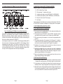
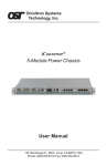
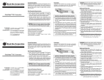
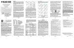
5.0 SPECIFICATIONS Model 5-Module AC 5-Module DC LMC3010A (1 Power Supply) LMC3080A (2 Power Supplies) LMC3012A (1 Power Supply) LMC3081A (2 Power Supplies) 5 5 Powe r Supply Capacity 1 or 2 Power Supplies 1 or 2 Power Supplies Powe r Re quire me nts 100-240VAC, 0.5A, 50/60Hz +36 to +60VDC, or -36 to -60VDC, 0.7A W:17.15"xD:9.0"xH:1.75" W:17.15"xD:9.0"xH:1.75" We ight 7.5 lbs (LMC3010A) 8.5 lbs (LMC3080A) 7.5 lbs (LMC3012A) 8.5 lbs (LMC3081A) Compliance UL, CE, FCC Class B UL, CE, FCC Class B 0 to 50 C -40 to 80 C 0 to 50 C -40 to 80 C 0-90% 0-90% 0-10,000 ft 0-10,000 ft 43,000 (1 Power Supply) 173,000 (2 Power Supplies) 49,700 (1 Power Supply) 198,800 (2 Power Supplies) M ode l Numbe r M odule Capacity Dime nsions Te mpe rature - Ope rating - Storage Humidity (non-conde nsing) Altitude M TBF (hrs) 6.0 CUSTOMER SUPPORT INFORMATION Order toll-free in the U.S.: Call 877-877-BBOX (outside U.S. call 724-746-5500) FREE technical support 24 hours a day, 7 days a week; Call 724-746-5500 or fax 724-746-0746 Mailing address: Black Box Corporation, 1000 Park Drive, Lawrence, PA 15055-1018 Web site: www.blackbox.com E-mail: [email protected] Form 040-L3010-001B 5/04 Page 12 Dynamic Fiber Conversion System 5-Module Power Chassis User Manual 1000 Park Drive · Lawrence, PA 15055-1018 724-746-5500 · Fax 724-746-0746 Page 1 TRADEMARKS All applied-for and registered trademarks are the property of their respective owners. o Save the packing material of the new power supply for return shipment of the faulty power supply or for future reuse. FEDERAL COMMUNICATIONS COMMISSION AND CANADIAN DEPARTMENT OF COMMUNICATIONS RADIO FREQUENCY INTERFERENCE STATEMENTS This equipment generates, uses, and can radiate radio frequency energy and if not installed and used properly, that is, in strict accordance with the manufacturers instructions, may cause interference to radio communication. It has been tested and found to comply with the limits for a Class A computing device in accordance with the specifications in subpart J of Part 15 of FCC rules, which are designed to provide reasonable protection against such interference when the equipment is operated in a commercial environment. Operation of this equipment in a residential area is likely to be cause interference, in which case the user at his own expense will be required to take whatever measures may be necessary to correct the interference. Changes or modifications not expressly approved by the party responsible for compliance could void the users authority to operate the equipment. This digital apparatus does not exceed the Class A limits for radio noise emission from digital apparatus set out in the Radio Interference Regulation of the Canadian Department of Communications. Le présent appareil numérique német pas de bruits radioélectriques dépassant les limites applicables aux appareils numéirques de las classe A prescrites dans le Règlement sur le brouillage radioélectrique publié par le ministère des Communications du Canada. 4.3 Hot Removal of DC Power Supply NORMAS OFICIALES MEXICANAS (NOM) ELECTRICAL SAFETY STATEMENT 1. Todas las instrucciones de seguridad y operación deberán ser leídas antes de que el aparato eléctrico sea operado. 2. Las instrucciones de seguridad y operación deberán ser guardadas para referencia futura. 3. Todas las advertencias en el aparato eléctrico y en sus instrucciones de operación deben ser respetadas. 4. Todas las instrucciones de operación y uso deben ser seguidas. 5. El aparato eléctrico no deberá ser usado cerca del aguapor ejemplo, cerca de la tina de baño, lavabo, sótano mojado o cerca de una alberca, etc. 6. El aparato eléctrico debe ser usado únicamente con carritos o pedelstales que sean recomendados por el fabricante. 7. El aparato eléctrico debe ser montado a la pared o al techo sólo como sea recomendado por el fabricante. 8. ServicioEl usuario no debe intentar dar servicio al equipo eléctrico más allá a lo descrito en las instrucciones de operación. Todo otro servicio deberá ser referido a personal de servicio calificado. 9. El aparato eléctrico debe ser situado de tal manera que su posición no interfiera su uso. La colocación del aparato eléctrico sobre una cama, sofá, alfombra or superficie similar puede bloquea la ventilación, no se debe colocar en libreros o gabinetes que impidan el flujo de aire por los orificios de ventilación. 10. El equipo eléctrico deber ser situado fuera del alcance de fuentes de calor como radiadores, registros de calor, estufas u ostros aparatos (incluyendo amplificadores) que producen calor. 11. El aparato eléctrico deberá ser connectado a una fuente de poder sólo del tipo descrito en el instructivo de operación, o como se indique en el aparato. 12. Precación debe ser tomada de tal manera que la tierra fisica y la polarización del equipo no sea eliminada. 13. Los cables de la fuente de poder deben ser guiados de tal manera que no sean pisados ni pellizcados por objetos colocados sobre o contra ellos, poniendo particular atención a los contactos y receptáculos donde salen del aparato. 14. El equipo eléctrico debe ser limpiado únicamente de acuerdo a las recomendaciones del fabricante. 15. En caso de existir, una antena externa deberá ser localizada lejos de las lineas de energia. 16. El cable de corriente deberá ser desconectado del cuando el equipo no sea usado por un largo periodo de tiempo. 17. Cuidado debe ser tomado de tal manera que objectos liquidos no sean derramados sobre la cubierta u orificios de ventilación. 18. Servicio por personal calificado deberá ser provisto cuando: A: El cable de poder o el contacto ha sido dañado; u B: Objectos han caído o líquido ha sido derramado dentro del aparato; o C: El aparato ha sido expuesto a la lluvia; o D: El aparato parece no operar normalmente o muestra un cambio en su desempeño; o E: El aparto ha sido tirado o su cubierta ha sido dañada. Page 2 o Determine which power supply is faulty by observing the status of the LEDs in the DFCS MGT module or viewing the status from the network management software. o Power Supply 1 (PS1) refers to the power supply on the right (as viewed from the front). Power Supply 2 (PS2) refers to the power supply on the left. o LED being ON indicates that the power supply supplies power. LED being OFF indicates that the power supply is not present. Blinking LED indicates that a power supply is installed but does not supply power because it is not properly connected to a power source or because it is faulty. o Once you determine that your DC source is connected properly, and the power supply LED is still not ON, determine which is the failing power supply unit and proceed to the next step. o Locate the DC circuit breaker, and switch the circuit breaker to the OFF position. o Remove the DC power cables of the faulty power supply from the DFCS power supply unit. o Using a screwdriver, loosen the 2 thumb screws securing the power supply to the main chassis (refer to Fig 6). o Remove the failing power supply. 4.4 Hot Attachment of DC Power Supply o Unpack the power supply carefully. Inspect for any damage. If any damage is observed, do not use the power supply and call 724-746-5500 to report the damage immediately and request a replacement unit. o Align the guide rails on the chassis with the rails on the bottom of the power supply; slide in the power supply ensuring that the power supply is seated firmly against the backplane and tighten the thumb screws securely with a screwdriver. o Locate the DC circuit breaker and make sure that the switch is in the OFF position. o Reconnect the DC power source to the DFCS power supply. o Locate the DC circuit breaker and switch the circuit breaker to the ON position. o Watch and listen to the fan in the rear of the power supply to ensure it is powered. o Save the packing material of the new power supply for return shipment of the faulty power supply or for future reuse. Page 11 Dynamic Fiber Conversion System 5-Module Power Chassis User Manual 4.0 POWER SUPPLY REPLACEMENT CAUTION: To remove power from the chassis, remove power cord from all power supplies. WARNING!!! NEVER ATTEMPT TO OPEN THE CHASSIS OR SERVICE THE POWER SUPPLY OR FAN MODULE. OPENING THE CHASSIS MAY CAUSE SERIOUS INJURY OR DEATH. THERE ARE NO USER REPLACEABLE OR SERVICEABLE PARTS IN THIS UNIT. 1. 0 GENERAL DESCRIPTION The Dynamic Fiber Conversion System (DFCS) 1U (1.75 inch) 5-Module Power Chassis is powered by up to two (2) hot-swappable and redundant universal AC or DC power supplies and can accommodate up to 5 DFCS media converters. It is ideal for enterprise Local Area Network (LAN) or Metropolitan Area Network (MAN) applications where managed media converters with high density and a small rackfootprint are important. The power supplies are hot swappable and can be replaced without shutting the chassis down. However, when removing and replacing a power supply unit, the following steps must be strictly followed in order to prevent serious injury or death or serious damage to your equipment. Removal of power supplies or cards will result in access to hazardous electrical. 4.1 Hot Removal of AC Power Supply o Determine which power supply is faulty by observing the status LEDs on the DFCS MGT or viewing the status from the network management software. o Power Supply 1 (PS1) refers to the power supply on the right (as viewed from the front). Power Supply 2 (PS2) refers to the power supply on the left. o LED being ON indicates that the power supply is supplying power. LED being OFF indicates that the power supply is not present. Blinking LED indicates that a power supply is installed but does not supply power because it is not properly connected to a power source or because it is faulty. o Once you determine that your AC plug is connected properly to an AC wall outlet, and the power supply LED is still not ON, determine which is the failing power supply unit and proceed to the next step. o Remove the AC power cord of the faulty power supply from the wall outlet. o Remove the AC power cord of the faulty power supply from the power supply unit. o Using a screwdriver, loosen the 2 thumb screws securing the power supply to the main chassis (refer to Fig 5). o Remove the failing power supply. 4.2 Hot Attachment of AC Power Supply o Unpack the power supply carefully. Inspect for any damage. If any damage is observed, do not use the power supply and call 724-746-5500 to report the damage immediately and request a replacement unit. o Align the guide rails on the chassis with the rails on the bottom of the power supply; Slide the power supply in, ensuring that the power supply is seated firmly against the backplane and tighten the thumb screws securely with a screwdriver. o Plug the AC cord to the back of the power supply. o Plug the AC cord to the AC wall outlet. o Watch and listen to the fan in the rear of the power supply to ensure it is powered. Page 10 Fig. 1 5-Module Chassis (Shown without modules installed) This User Manual describes the following models: DFCS 5-Module Power Chassis Options Configuration 5-Module AC 5-Module DC One (1) Power Supply LMC3010A LMC3012A Two (2) Power Supply LMC3080A LMC3081A Spare Power Supply LMC3011P LMC3013P 1.1 Terms Backplane A printed circuit board which is permanently mounted inside the chassis and is populated with receptacle connectors into which modules are inserted. Module A DFCS plug-in card positioned into a slot location and inserted into a backplane connector. Module-Guide A mechanical channel, guiding module insertion into a backplane connector. Slot A single chassis position consisting of a backplane connector and its associated module-guides. A Link A backplane slot-to-slot connection that provides Ethernet connectivity between adjacent slots (sometimes referred to as A Backplane Link). A Port An interface on a module capable of Ethernet traffic via the backplanes A Link. Page 3 B Link A backplane slot-to-slot connection that provides Ethernet connectivity between adjacent slots (sometimes referred to as B Backplane Link). B Port An interface on a module capable of Ethernet traffic via the backplanes B Link. 1.2 Mechanical Description The 5-Module chassis consists of any combination of one or two AC or DC power supplies. As can be seen from the model table above, four models have been preconfigured with one and two power supplies. Any other combination of AC and DC power supplies are permitted. The power supplies provide power to the chassis 5 backplane connectors. 1.3 Backplane Architecture The chassis features 5 module slots numbered 1 (left-most positioned slot) through 5 (right-most positioned slot). As modules are inserted into the chassis slots, they are seated into the slot connectors. The A and B Links provide Ethernet connectivity between adjacent slots. o Installation of the equipment should be such that the air flow in the front and back of the unit is not compromised or restricted. o Installing this equipment into a rack in such a way as to make it unstable may cause injury or death. Always make sure that the rack you are installing this equipment into is properly secured, stable, balanced and designed to carry the weight and weight distribution of this equipment. o Never use this equipment to carry any weight except its own. Never use it as a shelf to support the weight of other equipment. 3.4 DC Powered Chassis Mounting and Cabling o If rack mounting the chassis to a 19 standard rack, first attach the two enclosed L shaped rack mounting brackets to the chassis using the enclosed screws. o If rack mounting, mount and attach the chassis (after the mounting brackets are installed) to the rack using the appropriate rack mounting screws (not provided). o Locate the DC circuit breaker and switch the circuit breaker to the OFF position. o Prepare a power cable using a three conductor insulated wire (not supplied) with a 14 AWG gauge. Cut the power cable to the length required. o Strip approximately 3/8 of an inch of insulation from the power cable wires. o Connect the power cables to the DFCS Chassis by fastening the stripped ends to the DC power connector. WARNING: Note the wire colors used in making the positive, negative and ground connections. Use the same color assignment for the connection at the circuit breaker. o Connect the power wires to the circuit breaker and switch the circuit breaker ON. The fans should immediately begin to run and any installed DFCS modules will illuminate the power LEDs. Fig. 2 5-Module Backplane Architecture Thumb Screws Thumb Screws Fig 2. depicts the chassis backplane architecture including the A and B Links. The A Links connect between odd numbered slots on the left to even numbered slots on the right (i.e. 1-2, 3-4). The B Links connect between the even numbered slots on the left to odd numbered slots on the right (i.e. 2-3, 4-5). When modules with A and B Port capabilities are inserted into adjacent chassis slots, they can connect to each other via the backplane links and create flexible network architectures that meet the users requirements. Power Supply #1 Power Supply #2 Fig. 6 5-Module Chassis with two Installed DC Power Supplies Note that not all modules support and have backplane ports. To find out about each specific modules backplane port configuration, refer to the specific modules documentation. This chassis architecture facilitates a variety of applications including unmanaged, out-of-band managed, in-band managed and multi-port configurations. Page 4 Page 9 Thumb Screws Thumb Screws 1.4 Application Examples 1.4.1 Out-of-Band Managed 10/100Mbps Converter Application Power Supply #1 Power Supply #2 Fig. 5 5-Module Chassis with two Installed AC Power Supplies 3.3 DC Powered Chassis Site Preparation o Power source should be available within 5 ft. of the chassis. The over current protection for the connection with centralized DC shall be provided in the building installation and shall be a UL listed breaker rated at 20Amps, and installed per the National Electrical Code, ANSI/NFPA-70. o This equipment requires 36-60VDC/0.7 Amps power. Appropriate overloading protection should be provided on all DC power source outlets utilized. WARNING: Only a DC power source that complies with safety extra low voltage (SELV) requirements can be connected to the DC-input power supply. o When rack-mounting this equipment, the rack should be appropriately earth-grounded. o o o o WARNING REGARDING EARTHING GROUND: This equipment shall be connected to the DC supply system earthing electrode conductor or to a bonding jumper from an earthing terminal bar or bus to which the DC supply system earthing electrode is connected. This equipment shall be located in the same immediate area (such as adjacent cabinets) as any other equipment that has a connection between the earthed conductor of the same DC supply circuit and the earthing conductor, and also the point of earthing of the DC system. The DC system shall not be earthed elsewhere. The DC supply source is to be located within the same premises as this equipment. There shall be no switching or disconnecting devices in the earthed circuit conductor between the DC source and the earthing electrode conductor. o The operating temperature of this equipment is 0 to 50 degrees C. If installed in a closed or multi-unit rack assembly, the operating ambient temperature of the rack must not exceed the maximum rated 50 degrees C temperature. Page 8 Fig. 3 Out-of-Band Managed 10/100Mbps Converter Application Fig. 3 depicts an out-of-band managed 10/100 converter application. In this application, which is typical for a Central Office (CO) or a network core, a 5-Module chassis is loaded with 10/100 UTP to fiber converters that convert UTP cabling originating at a core switch to fiber and distributing the fiber in a star configuration to different customers. Out-of-band management is desirable in this application since it facilitates secure monitoring, configuration and trap notification of a large number of converter modules in the chassis. This application uses four 10/100 modules for UTP to fiber conversion and a SNMP or Telnet Management Module (MGT) for management. All modules are plugged into the 5-Module chassis. The 10/100 converter module is designed as a 4-port switch with two front-plane Ethernet ports (100Base-Fx fiber and 10/100Base-T/Tx UTP) and two 10/100 Ethernet backplane ports (A and B Ports). In this application, the A and B Ports are disabled to provide isolation between the modules. The MGT module features a 10Mbps Ethernet A Port. In this application, its A port is disabled and connectivity to the management network is performed via the MGT modules front-plane Ethernet port. It is important to emphasize that in this type of application, the A and B Ports of all of the 10/100 converters must be disabled to facilitate user data privacy by isolating the converters from each other and from the A and B Links. It should also be noted that in this configuration, in addition to data privacy infringement, enabling the A and B Links will cause a broadcast storm (since the modules create closed loops through the switch) or partitioning of some of the data paths by the switch. The management data flows between the MGT modules front-plane (out-of-band) and any secure and dedicated management network hardware. This configuration provides the network administrator with the ability to provide multicustomer service using a single chassis which is securely managed. Page 5 1.4.2 In-Band Managed 10/100Mbps Converter/Switch Application 2.0 UNPACKING, VISUAL INSPECTION AND INVENTORY Review the contents. The following items should be included: o DFCS 5-Module Power Chassis o 2 Rack mounting L brackets and 8 screws o 1 Installed power supply for model LMC3010A(AC) / LMC3012A(DC) o 2 Installed power supplies for model LMC3080A(AC) / LMC3081A(DC) o One power cord for each AC Power supply o User Manual Inspect equipment and immediately report any damage or discrepancies to Black Box at 724-746-5500. If equipment is damaged, do not apply power to the equipment. 3.0 SITE PREPARATION AND INSTALLATION 3.1 AC Powered Chassis Site Preparation Fig. 4 In-Band Managed 10/100Mbps Converter/Switch Application Fig. 4 depicts a 5-Module chassis with four modules plugged into adjacent backplane slots. In this application, which is typical for a Customer Premises (CPE) or Multiple Tenant Building, a 5-Module chassis is loaded with a 10/100 UTP to fiber converter that converts fiber cabling originating at a core switch and distributing the fiber uplink to different customers via 10/100 UTP. In this example, the module in Slot 1 is a SNMP or Telnet Management Module (MGT) that connects via its A backplane port to the 10/100-Fx in Slot 2 facilitating In-Band management (via the fiber uplink). The 10/100-Fx is connected via its B link port to a 4-port 10/100 switch module (4Tx/L2) in Slot 3, that is connected via its A link port to a second 4Tx/L2 module in Slot 4. This 4-module configuration provides an effective 9-port 10/100T managed switch with a fiber uplink configuration. o Power source should be available within 5 ft. of the chassis and installed per the National Electrical Code, ANSI/NFPA-70. o This equipment requires 100-240VAC, 0.5Amp, 50/60Hz. Appropriate overloading protection should be provided on all AC power source outlets utilized. o When rack-mounting this equipment, the rack should be appropriately earthgrounded. o The operating temperature of this equipment is 0 to 50 degrees C. If installed in a closed or multi-unit rack assembly, the operating ambient temperature of the rack must not exceed the maximum rated 50 degrees C temperature. o Installation of the equipment should be such that the air flow in the front and back of the unit is not compromised or restricted. o Installing this equipment into a rack in such a way as to make it unstable may cause injury or death. Always make sure that the rack you are installing this equipment into is properly secured, stable, balanced and designed to carry the weight and weight distribution of this equipment. o Never use this equipment to carry any weight except its own. Never use it as a shelf to support the weight of other equipment. 3.2 AC Powered Chassis Mounting o If rack mounting the chassis to a 19 standard rack, first attach the two enclosed L shaped rack mounting brackets to the chassis using the enclosed screws. o If rack mounting, mount and attach the chassis (after the mounting brackets are installed) to the rack using the appropriate rack mounting screws (not provided). o Attach the AC power cords (provided for each Power Supply) to the back of each Power Supply and plug into the AC outlets. The fans should immediately begin to run and any installed DFCS modules will illuminate the power LEDs. Page 6 Page 7