1
6. Connecting power
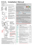
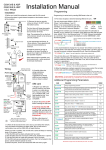
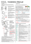
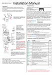
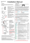
Connect the power as shown in the diagram below. (Do not use alarm or CAT5 cable)
Power only needs connected to the GSM cellular controller. It in turn feeds power to the
keypad and the illumination on the push button. The link wire shown should already be in
place. Please ensure the power adaptor is located within 10 feet of the intercom.
7. Connections on the cellular controller
Output to gate or lock – This is a
volt free momentary contact. The
pulse time is programmed by
software, and it can be latched and
unlatched by the user.
Exit button – This is an optional
input from an exit button or other
exit device to allow easy exit from
the property. When this is pressed,
the output relay will trigger for the
programmed time.
Optional input limit switch – This is useful for remotely checking if a door or gate is
opened or closed. The user can check remotely by SMS text message.
Pg 5. Installation instructions for BFT Cellular Intercom