1
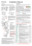
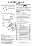
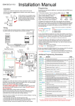
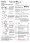
Installation & User Manual
For
Cellular Intercom System
BFT Americas
6100 Broken Sound Parkway N.W. Suite 14, Boca Raton, FL 33487
www.bft-usa.com
Toll Free: 877-995-8155
Office: 561-995-8155
Fax: 561-995-8160
P a g e |1
Contents
Overview of system
Site Survey
SIM card
Power
Call Box Overview
Mounting
Inserting the SIM Card
Connections on GSM Controller
Keypad Connections
Connecting to Gate controller
Other Wiring Tips
Powering Up
Programming GSM unit
GSM unit complete list of Parameters
Keypad Overview
Basic Keypad Programming
Full Keypad Programming
Using the Keypad
Using the Intercom
Control by SMS
Check if Gate Open/Closed
Using Optional App
Maintenance
Troubleshooting
P a g e |2
…………….Pg 3
…………….Pg 3
…………….Pg 3
…………….Pg 3
…………….Pg 4
…………….Pg 4
…………….Pg 4
…………….Pg 5
…………….Pg 5
…………….Pg 6
…………….Pg 6
…………….Pg 6
…………….Pg 7
…………….Pg 9
…………….Pg 10
…………….Pg 10
…………….Pg 10
…………….Pg 12
…………….Pg 12
…………….Pg 13
…………….Pg 13
…………….Pg 13
…………….Pg 14
…………….Pg 14
Overview of System
Please read this entire manual before attempting to install this system.
This system should only be installed by a professional automatic gate installer or access control
specialist dealer.
It is recommended that the system be set up, configured, commissioned and tested on a
workshop bench before taken to site for installation.
Site Survey
Before installing this system, you need to be sure that there is good mobile GSM cell coverage in
the area it is to be installed. It is recommended that you conduct a site survey, and check
reception on the site for a GSM network. If reception is poor in the area, then this system is not
recommended. This unit can operate on At&T and T-Mobile networks in the USA.
SIM Card
You will need a SIM card in order to use this system. It should be a regular voice and SMS text
SIM card. Do not use a data only SIM, as this is only for tablets and will not work in the unit.
1) Ensure the SIM has calling credit, and can make and receive
calls on a cell phone.
2) Check that the SIM is not locked to a phone and can be used
in other devices. Call the service provider to unlock it if required.
3) Check that the SIM does not have a PIN code request.
4) You are now ready to begin programming.
Power
This system comes with a 24v d.c. power supply. It is recommended that it is located within 25
feet of the intercom and cabled in 14 gauge cable.
24v dc
1amp power
supply
Call box
Tip: 18 gauge cable will not run the unit. You may
experience various issues with performance if
using 18 gauge or thinner, at more than 15 feet
distance.
The device uses peak current of up to 2 Amps!
If 18 gauge cable has already been installed,
doubling or trebling up cores may be sufficient.
14 Gauge Power cable
25 feet max
P a g e |3
Call Box Overview
Built in antenna
Security access key
Microphone
Keypad
status
Speaker grill
Optional
Keypad
Call button
Hinged front door
Tip: Keep app protective covers and films on the unit until fully installed. These covers are to
protect the unit from scratches during installation.
Mounting
5/16 (M8)
bolts
3" hole
centres
Hinge
front door
3" hole
centres
Wall mount
Hinge front
door
Gooseneck mount
Inserting the SIM card
Note: This unit is a dual 2G/3G system, operating on either 2G or 3G network frequencies of
850/900/1800/1900MHz.
close
open
1)
2)
3)
4)
5)
P a g e |4
Please ensure the SIM card is a 2G/3G compatible SIM card. Do not use a
SIM card for a tablet, as these only support data, and do not support voice and
SMS. You simply require a mobile phone type SIM card.
Put the SIM into a phone to activate and register it with the network.
If you are using pay and go, top up the SIM with some airtime credit.
Test that the SIM can make and receive calls and can send and receive a SMS.
Ensure the power is OFF.
Slide the SIM card holder in the open direction, and carefully open the door. Do NOT
force it.
Connections on the GSM Controller
GSM
modem
close
open
DETECT
GND
PB
GND
VCC
AC
AC
N/O
COM
N/C
24v dc
+
-
Output
to gate
or lock
Optional
input limit
switch
from gate
Exit button
Code Lock Keypad connections (Keypad versions only)
Tamper
N/C
OUT3
N/O
COM
N/C
+ -
egress
N/O
COM
N/C
N/O
COM
N/C
Power from
GSM unit
INT Lock
O/P1 inhib
Sense
(-)GND
DU out
K or A
Commonly used connections
Outputs – This keypad has 3 outputs. All can be
programmed for momentary and latching operation.
For gate systems and AC strike locks, connect a
keypad relay (normally open) in parallel with the GSM
module relay. For magnetic locks, connect in series
with normally closed contact.
Egress – This is for an optional exit button input,
connected across this terminal and GND (-).
OUT1 OUT2
Advanced connections
INT Lock – Used to operate a door in conjunction with another keypad. 24v dc max voltage,
100mA sink.
O/P1 inhib – When closed, this disables all codes for relay group 1.
Sense – N/C connected to (-)GND, to be connected to N/C door contact. Can be used to generate
door open or tamper alarm.
DU out – switches to (-) ground after the Duress Code is entered. Used to trigger alarm zone, or
buzzer to notify guard. 100mA sink, 24VDC.
K or A – Not used.
P a g e |5
Connecting to a Gate Controller
Intercom
GSM Cellular
controller
N/O
Common
N/O COM
Start
COM
Keypad
Gate motor
controller
Other Wiring Tips
Connecting DC magnetic
lock
GSM
output
Optional
keypad
output
Connecting AC/DC strike
lock
GSM
output
Lock
Separate
PSU
Optional
keypad
output
Lock
Separate
PSU
Powering Up
Perform a final check of wiring and ensure the antenna is connected before switching on the
power. Once the power is switched on, the power LED should illuminate and the unit will emit a
series of bleeps and then stop after approx. 8 seconds.
Power LED
GSM LED
Searching
Network found
close
CPU LED
Standby
Busy
P a g e |6
open
GSM
modem
TIPS:
My GSM LED is still searching / Unit Bleeping…
-Check SIM card is registered and can make call in cell
phone.
-Check the SIM card is seated correctly. Power off,
clean the contacts on the SIM and the GSM unit, and
reinsert the SIM. (Lightly sand).
-Check power cable distance and thickness.
-Change network.
-Fit a high gain antenna.
Programming
TIP: The GSM unit programming is by sending SMS text messages to the unit from a phone.
Step 1: Check Reception
Send the SMS *20# as shown, to the SIM card
number of the intercom. The unit should reply with a
reception level between 1 and 31.
*20#
Signal
level = 19
1-12
Poor
13-20
Medium
21-31
Good
Note: Reception levels below 14 can give problems with the
relay operation, and poor quality audio, or no audio coming
from the microphone on the intercom (the person on the
phone cannot hear anything), or buzz on the loud speaker.
TIP: If reception levels are low, take action now! Either increase the height of the antenna to
improve reception or request a higher gain antenna from your distributor or change to another
network which may have better coverage.
Step 2: Programming dial out numbers
Programing text messages must start with a pass code string, followed by a command, followed
by data, and each command is separated in the SMS by #.
To begin, program the unit to dial numbers when the call button is pressed. This module will dial
up to 3 telephone numbers in sequence.
*12*1234#110987654321#
Pass code
Data
Function code
TIP…
11 = Telephone number 1.
12 = Telephone number 2.
13 = Telephone number 3.
The phone image shows an example of a number being
stored and the reply sent by the unit to confirm OK.
Up to 3 numbers can be sent in a single SMS. The pass
code only needs entered at the beginning of each message,
and then each new command string is separated by #.
E.g. *12*1234#11firstnumber#12secondnumber#13thirdnumber#
P a g e |7
*12*1234#
110987654
321#
11098765
4321 OK
Step 3: Calling time
This is the time the unit will spend attempting to call a number before aborting the call and calling
the next number on the list. It is very useful to adjust this time so that if there is voicemail or
answer machine on a number, that the intercom aborts the call before the machine picks up,
otherwise the unit will think the call is answered and never call the next number. To adjust this
time, send the following SMS messages…
*12*1234#52??# (Where ?? = ringing time in seconds 10-99. Default = 20)
TIP: Remember to include the network connection time. A mobile phone needing to ring for 10
seconds may need a programmed ringing time of 15 seconds, because it can take 5 seconds to
connect the call.
Step 4: Caller ID access control
This feature allows up to 100 numbers to be stored in memory. Any of these numbers can call the
intercom. It will recognise the number, end the call without answering, and activate the output
relay, all within a few seconds.
First you must tell the unit which country it is operating in
by entering the country code of your country. If you do
not know the country code, it can be found online. Some
examples are shown below..
UK - 44
USA - 1
The example shows USA country code being entered.
TIP: Do not add any leading zero’s in front of the country
code.
*12*1234#
711#
711# OK
Now you may add numbers which can call the unit to trigger the relay by sending the following
SMS (up to 3 phone numbers can be sent in a single SMS…
*12*1234#72telephonenumber#72telephonenumber#72telephonenumber#
Just send the complete number as you would normally dial it from a phone.
Tip: Even if a number is stored as a dialling out number when the call button is pressed, it needs
stored again under the 72 feature if it is also required to have caller ID access.
Important: Some US networks automatically insert the long distance 1 in front of a number
when you call it on your phone, and some do not. You may need to enter phone numbers
in this section either with, or without long distance 1 in front. Please try both methods to
see which works in your area.
E.g. number 702-999-9999 may need stored as 1-702-999-9999.
P a g e |8
GSM unit complete list of parameters
The table below show the complete list of features in the cellular part of the intercom.
TIP: Programming messages below must begin with *12*1234# (if 1234=default passcode)..
Parameter
01????#
02????#
03????#
Description
Default
Changing pass codes
Change programming password
Change access control password (SMS control of relays, or non-stored
numbers can call intercom & enter code to activate output 1).
Change monitoring mode password (user can call the intercom, enter this
pass code to listen in and speak)
1234
5678
1212
1n????#
Dial out numbers
Store dialling out numbers. (n = 1, 2 or 3 position)
N/A
1n*#
Delete a dial out number. (n = 1, 2 or 3)
N/A
3?#
Volume controls
Speaker volume. Where ? = 1-3. 1 = lowest, 3 = highest.
3
4?#
Microphone volume. Where ? = 1-3. 1 = lowest, 3 = highest.
3
51?#
Timings
Relay 2 time. ? = seconds, 1-9999.
1 sec
52??#
Calling time - adjust this to avoid voicemail picking up a call (10-99 secs)
20 secs
53????#
Talking time. 005-999 seconds. Must be 3 digits.
Max monitoring time (for listen in mode when calling the intercom) 00-60
mins. 00 = no limit.
60 secs
55??#
10 mins
58?#
Scheduled service calls
Store a service number to receive a scheduled call or SMS from the unit
and prevent inactive SIM being turned off by provider.
Set the time schedule for the intercom to make a scheduled call or SMS
to the service number. 00-60 day time schedule. 00 = no call or SMS.
Choose between scheduled call or scheduled SMS. 1 = SMS. 2 = call.
77*#
Delete the stored service number
71???#
Stores country code.
N/A
72number#
Store caller ID number. Max 14 digits. Only last 6 digits compared.
N/A
73number#
Delete caller ID number. (number = phone number to be deleted).
N/A
73*#
Delete all caller ID numbers
N/A
*20#
Service & diagnostic messages (no passcode required for these!)
Check reception level 1-31 (no passcode needed)
N/A
*21#
Check stored numbers. O = dial out number. I = dial in number. E = end
N/A
*22#
Check input status and relay status. (No passcode needed)
N/A
999#
Restore Defaults
Send with passcode string to clear all programming.
N/A
77number#
57??#
N/A
00
1
N/A
Caller ID features
P a g e |9
Keypad overview
Now that the GSM part of the intercom is programmed and working, you may now program the
keypad. The keypad is programmed directly on the keys, not remotely by SMS.
This keypad has 3 outputs. The diagram below shows the LED indicators which indicate
programming and relay status information.
ON when incorrect codes entered and outputs are locked out.
GREEN when output 1 activated.
RED when output 2 activated.
1
2
3
FAST FLASHING – Wrong code entered / error.
4
5
6
SLOW FLASHING - in normal standby mode.
7
8
9
ON in programming mode.
*
0
#
ON when relay 3 activated.
TIP: After power up, as a security precaution, the keypad cannot be programmed for 60 seconds.
Once this time elapses, you may begin.
TIP: Flashing amber LED is normal standby mode!
Basic Keypad Programming
Quick start guide
1) Enter programming mode (amber LED should be ON)
0
0
0
0
*
*
2) Enter a new user code...
1
0
2
0
0
0
?
?
?
?
3) Exit programming mode
*
#
Tip: The engineer code
must be the same length as
user codes. So if using a 6
digit engineers code, then
user codes must also be 6
digits long etc.
*
4) Enter the new user code to check the relay clicks.
Full Keypad programming
Enter programming mode..
0
0
0
0
*
Exit programming mode..
*
*
P a g e | 10
*
The unit is now in programming mode. Amber LED on the
keypad should remain permanently on. 0000 is the default
engineer’s passcode.
The unit should exit programming mode and the amber LED
should start flashing again.
Enter a new ENGINEERS code…
Go into programming mode firstly then enter the following sequence…
0
1
?
Location
?
?
?
#
4-8 digit code
Replace ???? with your new ENGINEERS
code. (Code length must be same as user
code length).
Validate
Enter or delete new user codes
There are 3 groups of user codes. Group 10 for relay 1, group 20 for relay 2, and group 30 for
relay 3. The programming sequence is shown below…
1
0
2
0
10= relay 1 codes
(1000 available)
20= relay 2 codes
(100 available)
30= relay 3 codes
(100 available)
0
0
?
?
Memory locations
000-999 for relay 1
001-100 for relay 2
001-100 for relay 3
2= add code
5= delete code
?
?
#
Pin code 4-8 digits
Validate
Example: Add user 31 to have access code 5555 operating relay 2….
2
0
2
Group 2
0
Add code
3
1
5
Location 31
5
5
5
Pin code 5555
#
Validate
Programming relay output times and modes…
?
?
0
1
or
-
9
9
9
9
0 = start / stop toggle mode (latching)
1-99999 = seconds momentary operation
51=relay1
52=relay2
53=relay3
Delete a user code even if you don’t know the code…
?
?
10=relay1
20=relay2
30=relay3
5
?
Delete code
?
?
#
ID location to be deleted
Validate
Delete an entire group of codes
?
?
0
10=relay1 group
20=relay2 group
30=relay3 group
9
9
9
Super delete code
#
Validate
Programming super user codes…
A super user code can activate any of the 3 relays
0
2
Location
P a g e | 11
?
?
?
4-8 digit code
?
#
Validate
9
#
Validate
Restoring defaults
When in programming mode, you can enter the following sequence…
9
9
9
9
#
When the master code is forgotten….
1) Wire a push button (or replicate with wire link) across the Egress terminal and (-)GND.
2) Switch off power for 1 minute.
3) Switch ON power.
4) during the first 60 seconds, press the EG button once to enable the function.
5) Enter the following code..
8
0
8
0
*
*
The keypad should now be in programming mode, ready to accept new data.
Using the keypad
Using the standard codes…
Once you have exited out of programming mode, simply enter the user code.
Using super user codes
?
?
?
?
#
1
Activate output 1
?
?
?
?
#
2
Activate output 2
?
?
?
?
#
3
Activate output 3
Using the intercom
This cellular intercom can dial up to 4 numbers in sequence for any call button when pressed..
Dialling…..
Phone 1
Phone 2
Phone 3
Any user receiving the call can answer, speak to the visitor, and press the following digits on their
mobile or fixed line telephone to control the relay on the device…
Press * key to operate
electric gates or door lock.
Use this normally.
P a g e | 12
1
2
3
4
5
6
7
8
9
*
0
#
Press # key to LATCH output
relay. Caution: Use only for
holding open gates or door!.
Press 1 to UNLATCH output
which has previously been
latched. Use to allow gates/door
to close
Control by SMS
This intercom allows the user to send SMS commands to control the relays and check status as
follows…
*33*5678# - Relay momentary trigger.
*34*5678# - Relay latch ON or hold ON.
*35*5678# - Relay unlatch or switch OFF.
Check if door or gate is open or closed
*22#
Status =
OPEN,
Relay =
OFF
Send the SMS as shown, and the unit will reply showing the status
of the input limit switch (if used), and the relay..
This example shows that the input sensor is in OPEN state, and the
relay is OFF.
If the relay is latched, then the status will change to ON.
If the input limit witch is closed, the status shown will change to
CLOSED.
TIP: If there is not a physical limit switch fitted to the door or gate,
then the status input will always show OPEN.
Using the Optional App
Android and Iphone users can download an optional app called GSM-GATE. This app performs 3
main functions..
1) Speed dials your intercom when the trigger button is pressed.
2) Sends pre-configured SMS messages to latch and unlatch the relay.
3) Allow the user to check status like reception level and status of the output and input.
Main Trigger button
Use this to speed
dial intercom and
momentary trigger
the relay.
Latch Relay Button
Sends a preconfigured SMS to
latch on the relay.
Can be used to hold
open gates or door.
Trigger Gates
Hold
Open
Info screen
Information about manufacturer.
P a g e | 13
Unhold
/Close
Un-Latch Relay Button
Sends a pre-configured
SMS to unlatch the relay
if it has previously been
latched. Can be used to
allow gates to close
again.
Status features
Enter new screen to
check signal strength,
stored numbers, gate or
door status.
Settings screen
Setup screen, to enter sim card number of
intercom & SMS strings.
Maintenance of the Intercom
The intercom SIM card will need topped up occasionally if it is a pre-pay casual SIM card. It is
recommended that you register this SIM card on the provider’s web site. You can register card
payment details. Many networks offer an auto top up feature, which means they will automatically
top up your intercom when the balance runs low.
The stainless steel can dull or discolour over time in weather conditions. This can be polished with
a suitable stainless steel cleaner.
Troubleshooting guide
Q. The unit will not power up. No LEDs on.
A. Check power supply voltage at intercom is within 23.5-24.5v DC. Cable length from PSU to
intercom should be less than 15 feet.
Q. The unit powers up but is not showing network reception or will not respond to SMS.
A. This means the unit is not able to detect the network for some reason.
-Power off the unit, remove the SIM and check it in a mobile phone to verify it can make a call and
has calling credit.
-Disable any PIN code request if active on the SIM card.
-Check the SIM is a standard voice capable SIM. If you are unsure, contact your SIM card
provider to verify. Frequency of operation should be any one of international quad band
standards, 850 / 900 / 1800 / 1900 MHz.
-Check the reception is good. Poor reception is not sufficient.
-Check that the cable from power supply to intercom is less than 15 feet and that the cable
thickness is 1.5mm or 14 gauge. Alarm, CAT5 or thin gauge cable is not sufficient.
-Power off, remove the SIM, use fine sand paper to lightly sand the SIM pads and contacts on the
GSM unit, lightly bend the contacts upwards so that they make better contact with the SIM and try
again.
Q. The unit calls the first number, but there is not enough time to answer before it diverts
to the next number.
A. Increase the no answer time as per programming instructions.
Q. The unit calls the first number but voicemail comes on before it can ring the second
number.
A. Decrease the no answer time as per programming instructions.
Q. The caller ID part does not work.
A. Be sure to program the caller ID part under 72 feature. If your number is a private or number
withheld, then it will not work.
-Even if you have already programmed a number to receive a call from the intercom, if you also
want that number to have caller ID access, it must be programmed under the 72 feature also.
-Ensure the number is entered as you would normally dial it from another phone.
-For US customers, ensure the numbers have been entered with a leading 1. If this does not work,
try again without the leading 1.
P a g e | 14
Q. There is no audio from the gate, but the person at the gate can hear ok.
A. This can be due to low reception or excessively long power cables.
-Check reception level by *20#.
-Change SIM card if necessary to another network which may have better coverage.
-Purchase a high gain antenna.
This may also be caused by a defective microphone, water on a microphone from a sprinkler for
example, or dirt/insects blocking the microphone hole. If reception is optimum and the problem
persists, contact your supplier or installer.
Q. The audio quality that can be heard on the remote telephone is poor or humming
(buzzing).
A. A small amount of GSM buzz can be considered normal on GSM intercoms, but not so much
that causes inability to hear the person speaking. This can be caused by the GSM antenna being
mounted too close to the speech panel or not mounted high enough, or poor power cables being
too long or thin.
-Try earthling the speech panel chassis to 0V of the power supply.
-This is also a symptom of poor reception. Try above steps on checking and improving reception.
Q. The keys do not work when the intercom calls a phone.
A. Check if you can hear the relay clicking at the gate when the keys are pressed during a call. If it
can be heard, then the system is working, check wiring between the relay and the lock or gate
panel. If the relays do not make a clicking sound, then check this feature on a different mobile cell
phone or landline. If it works on a different phone, check the settings on the phone in question
under DTMF tones.
Failure of DTMF tones to operate correctly is also a symptom of low reception or insufficient
power cabling. Check steps above on improving reception or addressing the power problem.
-Some iphone users may experience trouble using the * key to trigger the gates. In this case, refer
to your distributor on how to change the trigger key to any other key. Also check that the relays
are not already latched with the *22# command. If they are latched, they need unlatched before
the trigger keys will work.
Q. The keypad confirmation bleeps when I enter my code but the gates or door lock does
not open.
A. Check wiring. The keypad relay should be connected to the lock or gate system as well as the
relay inside the GSM cellular part of the intercom.
- Do not wire power to the intercom in alarm cable or CAT 5 cable. It should be proper power
cable and the power cable length should be as short as possible. Otherwise relays may not fire.
Q. The system was operating the gates fine, but now it will not trigger the gates.
99% of the time, this is cause by the user accidentally latching the relay. This latches the output
relay permanently on. Send the intercom the following SMS *22#. The intercom should reply with
a message detailing the relay status.. If it has been latched, then the message will state “the relay
is ON”. In this case refer to the user guide to read how to unlatch it again.
Q. The unit no longer calls out to phones but I can make a call to it from my phone.
A – Check there is balance on the SIM card.
A – Switch off the power, remove the SIM, put it into a phone, and check that a call can be made
from a phone. This will verify if the SIM is still working and in service.
P a g e | 15
BFT Americas
6100 Broken Sound Parkway N.W. Suite 14, Boca Raton, FL 33487
www.bft-usa.com
Toll Free: 877-995-8155
Office: 561-995-8155
Fax: 561-995-8160
P a g e | 16