1
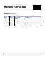
D4--DCM
Data Communications Module
Manual Number D4-DCM-M
WARNING
Thank you for purchasing automation equipment from PLCDirectä. We want your new DirectLOGICä automation
equipment to operate safely. Anyone who installs or uses this equipment should read this publication (and any other
relevant publications) before installing or operating the equipment.
To minimize the risk of potential safety problems, you should follow all applicable local and national codes that regulate
the installation and operation of your equipment. These codes vary from area to area and usually change with time. It is
your responsibility to determine which codes should be followed, and to verify that the equipment, installation, and
operation is in compliance with the latest revision of these codes.
At a minimum, you should follow all applicable sections of the National Fire Code, National Electrical Code, and the
codes of the National Electrical Manufacturer’s Association (NEMA). There may be local regulatory or government
offices that can also help determine which codes and standards are necessary for safe installation and operation.
Equipment damage or serious injury to personnel can result from the failure to follow all applicable codes and
standards. We do not guarantee the products described in this publication are suitable for your particular application,
nor do we assume any responsibility for your product design, installation, or operation.
If you have any questions concerning the installation or operation of this equipment, or if you need additional
information, please call us at 1--800--633--0405.
This publication is based on information that was available at the time it was printed. At PLCDirectä we constantly
strive to improve our products and services, so we reserve the right to make changes to the products and/or
publications at any time without notice and without any obligation. This publication may also discuss features that may
not be available in certain revisions of the product.
Trademarks
This publication may contain references to products produced and/or offered by other companies. The product and
company names may be trademarked and are the sole property of their respective owners. PLCDirectä disclaims any
proprietary interest in the marks and names of others.
Stage is a trademark of Koyo Electronics Industries Co., LTD. Texas Instruments is a registered trademark of Texas
Instruments, Inc. TI, TIWAY, Series 305, Series 405, TI305, and TI405 are trademarks of Texas Instruments, Inc.
Siemens and SIMATIC are registered trademarks of Siemens, AG. GE is a registered trademark of General Electric
Corporation. Series One is a registered trademark of GE Fanuc Automation North America, Inc. MODBUS is a
registered trademark of Gould, Inc. IBM is a registered trademark of International Business Machines. MS-DOS and
Microsoft are registered trademarks of Microsoft Corporation. Windows is a trademark of Microsoft Corporation.
OPTOMUX and PAMUX are trademarks of OPTO 22.
Copyright 1997, PLCDirectä Incorporated
All Rights Reserved
No part of this manual shall be copied, reproduced, or transmitted in any way without the prior, written consent of
PLCDirectä Incorporated. PLCDirectä retains the exclusive rights to all information included in this document.
1
Manual Revisions
If you contact us in reference to this manual, be sure to include the revision number.
Title: DL405 Data Communications Module
Manual Number: D4--DCM--M
Issue
Date
Effective Pages
Description of Changes
Original
1/94
Cover/Copyright
Contents
Manual History
Preface
1-1 -- 1-26
A-1 -- A-9
Original Issue
Rev. A
6/98
Entire Manual
Manual Revisions
Appendix A
Downsize to spiral
Rev. A
Added DL305/405 Cross Reference
1
Table of Contents
Introduction . . . . . . . . . . . . . . . . . . . . . . . . . . . . . . . . . . . . . . . . . . . . . . . . . . . . . . . . . . . . . . . . . . . . . . . . .
Overview . . . . . . . . . . . . . . . . . . . . . . . . . . . . . . . . . . . . . . . . . . . . . . . . . . . . . . . . . . . . . . . . . . . . . . . . .
Manual Layout . . . . . . . . . . . . . . . . . . . . . . . . . . . . . . . . . . . . . . . . . . . . . . . . . . . . . . . . . . . . . . . . . . . .
DCM Hardware . . . . . . . . . . . . . . . . . . . . . . . . . . . . . . . . . . . . . . . . . . . . . . . . . . . . . . . . . . . . . . . . . . .
Applications . . . . . . . . . . . . . . . . . . . . . . . . . . . . . . . . . . . . . . . . . . . . . . . . . . . . . . . . . . . . . . . . . . . . .
As a DirectNET Interface . . . . . . . . . . . . . . . . . . . . . . . . . . . . . . . . . . . . . . . . . . . . . . . . . . . . . . . . . .
As an Extra Communication Port . . . . . . . . . . . . . . . . . . . . . . . . . . . . . . . . . . . . . . . . . . . . . . . . . . . .
As a Modbusâ Network Interface . . . . . . . . . . . . . . . . . . . . . . . . . . . . . . . . . . . . . . . . . . . . . . . . . . . .
Specifications . . . . . . . . . . . . . . . . . . . . . . . . . . . . . . . . . . . . . . . . . . . . . . . . . . . . . . . . . . . . . . . . . . .
Environmental Specifications . . . . . . . . . . . . . . . . . . . . . . . . . . . . . . . . . . . . . . . . . . . . . . . . . . . . . . .
Operating Specifications . . . . . . . . . . . . . . . . . . . . . . . . . . . . . . . . . . . . . . . . . . . . . . . . . . . . . . . . . . .
Using Your DCM -- Five Steps . . . . . . . . . . . . . . . . . . . . . . . . . . . . . . . . . . . . . . . . . . . . . . . . . . . . .
1
2
3
4
5
5
6
6
7
7
7
8
Building the Communication Cable. . . . . . . . . . . . . . . . . . . . . . . . . . . . . . . . . . . . . . . . . . . . . . . . . . .
Consideration 1: Physical Configuration . . . . . . . . . . . . . . . . . . . . . . . . . . . . . . . . . . . . . . . . . . . . . .
Consideration 2: Electrical Specification RS232C or RS422 . . . . . . . . . . . . . . . . . . . . . . . . . . . . .
Consideration 3: Cable Schematics . . . . . . . . . . . . . . . . . . . . . . . . . . . . . . . . . . . . . . . . . . . . . . . . . .
Consideration 4: Cable Specifications . . . . . . . . . . . . . . . . . . . . . . . . . . . . . . . . . . . . . . . . . . . . . . . .
Consideration 5: Installation Guidelines . . . . . . . . . . . . . . . . . . . . . . . . . . . . . . . . . . . . . . . . . . . . . .
Consideration 6: A Quick Test Cable . . . . . . . . . . . . . . . . . . . . . . . . . . . . . . . . . . . . . . . . . . . . . . . . .
9
10
11
12
16
16
19
Setting the DCM Switches . . . . . . . . . . . . . . . . . . . . . . . . . . . . . . . . . . . . . . . . . . . . . . . . . . . . . . . . . . . .
Host Computer or Operator Interface Connection . . . . . . . . . . . . . . . . . . . . . . . . . . . . . . . . . . . . . .
DirectNET Interface Connection . . . . . . . . . . . . . . . . . . . . . . . . . . . . . . . . . . . . . . . . . . . . . . . . . . . .
DCM Switch Settings . . . . . . . . . . . . . . . . . . . . . . . . . . . . . . . . . . . . . . . . . . . . . . . . . . . . . . . . . . . . . .
Online / Offline Switch . . . . . . . . . . . . . . . . . . . . . . . . . . . . . . . . . . . . . . . . . . . . . . . . . . . . . . . . . . . . .
Address Selection Switch . . . . . . . . . . . . . . . . . . . . . . . . . . . . . . . . . . . . . . . . . . . . . . . . . . . . . . . . . .
21
21
22
23
25
26
Installing the DCM and Starting the Network . . . . . . . . . . . . . . . . . . . . . . . . . . . . . . . . . . . . . . . . . .
Install the DCM . . . . . . . . . . . . . . . . . . . . . . . . . . . . . . . . . . . . . . . . . . . . . . . . . . . . . . . . . . . . . . . . . . .
Connect the Cables . . . . . . . . . . . . . . . . . . . . . . . . . . . . . . . . . . . . . . . . . . . . . . . . . . . . . . . . . . . . . . .
If you’re using DirectNET... . . . . . . . . . . . . . . . . . . . . . . . . . . . . . . . . . . . . . . . . . . . . . . . . . . . . . . . . .
If you’re using an Operator Interface or Host Computer... . . . . . . . . . . . . . . . . . . . . . . . . . . . . . . .
If you’re using Modbusâ . . . . . . . . . . . . . . . . . . . . . . . . . . . . . . . . . . . . . . . . . . . . . . . . . . . . . . . . . . .
27
27
27
27
28
28
Verification and Troubleshooting. . . . . . . . . . . . . . . . . . . . . . . . . . . . . . . . . . . . . . . . . . . . . . . . . . . . . .
29
Appendix A: RLL Communications Programs . . . . . . . . . . . . . . . . . . . . . . . . . . . . . . . . . . . . . . . . .
A--1
Why do you need a communications program? . . . . . . . . . . . . . . . . . . . . . . . . . . . . . . . . . . . . . . . .
The Master Initiates Requests . . . . . . . . . . . . . . . . . . . . . . . . . . . . . . . . . . . . . . . . . . . . . . . . . . . . . .
Why Ladder Logic? . . . . . . . . . . . . . . . . . . . . . . . . . . . . . . . . . . . . . . . . . . . . . . . . . . . . . . . . . . . . . . . .
Identifying the master and slave . . . . . . . . . . . . . . . . . . . . . . . . . . . . . . . . . . . . . . . . . . . . . . . . . . . . . .
Location of Master and Slave . . . . . . . . . . . . . . . . . . . . . . . . . . . . . . . . . . . . . . . . . . . . . . . . . . . . . . .
Specifying the amount of data . . . . . . . . . . . . . . . . . . . . . . . . . . . . . . . . . . . . . . . . . . . . . . . . . . . . . . . .
Number of Bytes to Transfer . . . . . . . . . . . . . . . . . . . . . . . . . . . . . . . . . . . . . . . . . . . . . . . . . . . . . . . .
A--2
A--2
A--2
A--4
A--4
A--5
A--5
ii
Table of Contents
Designating the master station memory area . . . . . . . . . . . . . . . . . . . . . . . . . . . . . . . . . . . . . . . . . . A--6
Memory Area of Master . . . . . . . . . . . . . . . . . . . . . . . . . . . . . . . . . . . . . . . . . . . . . . . . . . . . . . . . . . . . A--6
Identifying the slave station memory area . . . . . . . . . . . . . . . . . . . . . . . . . . . . . . . . . . . . . . . . . . . . . A--7
Memory Area of Slave to Read or Write . . . . . . . . . . . . . . . . . . . . . . . . . . . . . . . . . . . . . . . . . . . . . . A--7
Controlling the communications . . . . . . . . . . . . . . . . . . . . . . . . . . . . . . . . . . . . . . . . . . . . . . . . . . . . . . A--8
Communications Special Relays . . . . . . . . . . . . . . . . . . . . . . . . . . . . . . . . . . . . . . . . . . . . . . . . . . . . A--8
Multiple Read and Write Interlocks . . . . . . . . . . . . . . . . . . . . . . . . . . . . . . . . . . . . . . . . . . . . . . . . . . . A--9
DL305/405 Cross Reference . . . . . . . . . . . . . . . . . . . . . . . . . . . . . . . . . . . . . . . . . . . . . . . . . . . . . . . . A--10
Introduction
In This Section. . . .
— Overview
— DCM Hardware
— Applications
— Specifications
— Using the DCM -- Five Steps
1
2
Introduction
Overview
The Purpose of
this Manual
This manual is designed to allow you to setup
and install your DL405 Data Communications
Module (DCM). This is the only manual you will
need if you are using the DCM as an extra
general purpose communication port for your
DL405 PLC system. If you plan on using the
DCM as a network master or slave on a
DirectNET network, we suggest that you read
the DirectNET manual first. The DirectNET
manual provides detailed descriptions of
network configurations, protocol, and the PLC
programs that are necessary to control
communications with the DCMs.
If you plan on using a personal computer as the network master, it may be helpful to
read the DirectNET manual first. In either case, the DirectNET manual can be
useful because it provides detailed descriptions of network configurations, various
cable connections, etc.
Supplemental
Manuals
Depending on which products you have purchased, there may be other manuals that
are necessary or helpful for your application. These are some suggested manuals:
User Manuals
D
DirectNET Network Guide
part number
DA--DNET--M
D
DirectSoft Programming Software
part number
DA--DSOFT--M
If you plan to use your D4--DCM to communicate with another PLC, you will need the
appropriate user manual for the other PLC.
If you plan to use your D4--DCM module as an interface to HMI or PC Control
software or to an Operator Interface panel, you will need to refer to the
documentation for that product.
Who Should Read
this Manual
If you need an additional communications port for your DL205 PLC and you
understand the basics of installing and programming PLCs, this is the right manual
for you. This manual gives you the information you need to set up an active port on
the D4--DCM module.
Quality Technical
Manuals and
Technical Support
We strive to make our manuals the best in the industry. We rely on your feedback to
let us know if we are reaching our goal. If you cannot find the solution to your
particular application, or, if for any reason you need additional assistance, please
call us at 800--633--0405. Our technical support group is glad to work with you in
answering your questions. They are available weekdays from 9:00 a.m. to 6:00
p.m. Eastern Time. You can also contact us on the worldwide web at:
http://www.plcdirect.com
(PLCDirect Web site for general info/file transfers)
You can also find a variety of support solutions at our 24--hour per day BBS at:
770--844--4209
If you find a problem with any of our products, services, or manuals, please fill out
and return the ’Suggestions’ card that came with this manual.
Introduction
Steps
1
2
3
The main contents of this manual are organized into five steps:
Introduction
Build the Cable
Set the DCM Switches
tells you about the Data Communication Module and its
uses. It lists other manuals you may need and tells you how
to get additional technical assistance, if necessary.
guides you through building the necessary communication
cable, covering physical and electrical specifications.
guides you through the setup of the rotary and DIP switches
to select communication parameters and network
addressing. It shows the proper method of inserting the
module into the base.
tells you what to consider when laying out your network
4
Install the DCM and Start cable and how to terminate the individual conductors at the
networked devices. It gives you specific cabling examples,
the Network
5
introduces the use of the DCM’s status indicator lights as a
diagnostic tool. It gives you status indicator light patterns to
help you identify problems that could be preventing
communications.
Appendix
A
showing pinouts for each device.
Verify and Troubleshoot
Additional reference information for the D4--DCM is available in this appendix:
RLL Communications
Programs
provides helpful examples of Ladder Logic programs for
DCM communications.
33
4
Introduction
DCM Hardware
The following diagram shows the major DCM components. The address selection
switches and the communication dipswitches are of special importance.
PWR
OK
NAK
ENQ
TOUT
HDR
MSTR
DATA
Status Indicators
(shown below)
Base Connector
Online/Offline Switch
Address Selection Switch
DIP Switches for
communications
and protocol parameters
RS232C/RS422
Communication Port
Status Indicators
Self Test Indicator: ON
Module Power: ON
NAK: ON if a NAK is
either sent or received
TOUT: ON if a timeout
has occurred in the DCM
Master Mode:
ON if master
OFF if slave
DCM Uses
PWR
OK
NAK
ENQ
TOUT
HDR
MSTR
DATA
Send/Receive Enquiry:
FLASHING*
Send/Receive Header:
FLASHING*
Send/Receive Data
Packet: FLASHING*
The DL405 Data Communications Module (DCM) is a general purpose
communications interface for the DL405 family of Programmable Logic Controllers
(PLCs). This module is primarily used for three reasons.
D
As a network interface to a DirectNET network
D
As an extra general purpose communications port to connect a personal
computer or operator interface
D
As a network interface to a ModbusR network using the RTU protocol
The following pages provide an overview of these uses, along with the information
you need to connect the DCM.
Introduction
Applications
As a DirectNET
Interface
The DCM can be used as a network interface for applications that require data to be
shared between PLCs, or between PLCs and an intelligent device (such as a host
computer). The DCM easily connects to DirectNET. This network allows you to
upload or download virtually any type of system data including Timer/Counter data,
I/O information, and V-memory information.
Using a DCM as part of a PLC Network Master — The DCM can be used in a
DL405 PLC station that is serving as a network master. (A master is the network
station that initiates requests for data from other stations on the network). The DCM
takes communication requests issued from the PLC program and automatically
converts these requests into network commands that read data from or write data to
another network station.
The PLC program is really very simple and only requires a few instructions. You do
not have to be a PLC programming guru to use the network. Appendix A provides an
overview of the instructions used. (If you want even more information, see the
DirectNET Manual).
Using a DCM as part of a PLC Network Slave — The DCM can also be used in a
DL405 PLC station that is serving as a network slave station. In this case, the DCM
“listens” to the network for any messages that contain the DCM’s address. The DCM
deciphers the network commands, carries out the request to read or write data, and
sends confirmation and/or information to the master station.
DirectNET Slaves
Slaves respond to
the master’s request
Response
Communicate with
either a PC or
DirectNET Slaves
Request
55
6
Introduction
As an Extra
Communication
Port
As an extra communication port, the DCM has specifications similar to the bottom
port on the DL405 PLCs. Plus, the DCM can communicate at higher baud rates. If
you can connect a device to the bottom port on the DL405 PLC, then you can also
connect the same device to the DCM. These devices can be a variety of things, such
as operator interfaces or personal computers.
Since the DCM does not require any programming, you can simply set the DCM
communication parameters, connect the appropriate RS232C or RS422 cables,
and start transferring data.
Quickly add extra Communication ports*
* Number of DCMs is limited by the available power budget
As a Modbusâ
Network Interface
The DCM can be used as a slave station interface to connect your DL405 system to
the Modbusâ network using the Modbusâ RTU protocol. The host system must be
capable of issuing the Modbusâ commands to read or write the appropriate data.
This manual does not describe the Modbusâ protocol. You must reference the
Gould Modbusâ Protocol Reference Guide for details (P1-MBUS-300 Rev. B).
There may be more recent editions of this manual, so check with your Modbusâ
supplier before ordering the documentation. (A cross reference for the Data Types is
supplied later in this manual).
Modbusâ Master
Modbusâ Network using RTU Protocol
Network
Slave
Network
Slave
DL405 Slave
with DCM
As a slave station....
responding to network requests
Introduction
Specifications
Environmental
Specifications
Operating
Specifications
Operating Temperature
32° F to 140° F (0° to 60° C)
Storage Temperature
--4° F to 158° F (--20° to 80° C)
Operating Humidity
5 to 95% (non-condensing)
Air Composition
No corrosive gases permitted
Vibration
MIL STD 810C 514.2
Shock
MIL STD 810C 516.2
Voltage Isolation
1500 VAC, 1 minute duration
Insulation Resistance
10M ohms at 500 VDC
Noise
NEMA ICS3--304
Power Budget Requirement
500 ma @ 5 VDC
Maximum number of modules
limited only by power budget
Location of module
CPU base only
any slot except Slot 0 or CPU slot
Interface
Serial RS232C / RS422
half-duplex, DTE, Asynchronous,
8 bits/character
Baud Rates
300 to 38.4K baud, switch selectable
Maximum Distance
RS232C -- 49ft (15 meters)
RS422 -- 3300 feet (1000 meters)
Protocol
DirectNET1
K-sequence (proprietary)
MODBUSâ RTU
Diagnostics
Automatic check of ROM/RAM,
communications, switch settings,
and LEDs
Note 1: Also compatible with Hostlink and/or CCM2 protocols. These names were used by previous vendors of
compatible Koyo designed products.
77
8
Introduction
Using your DCM-- Five Steps
Complete the following steps to connect
the DCM.
STEP 1. Familiarize yourself with the
communications options of DCM
in the Introduction.
STEP 2. Build the communication cable
that fits your needs.
STEP 3. Set the DCM switches. (Baud
rate, parity, etc).
Cable
Switches
Install
STEP 4. Install the DCM.
Verify (Troubleshooting)
STEP 5. Verify correct network operation.
PWR
NAK
TOUT
MSTR
OK
ENQ
HDR
DATA
Building the Communication Cable
Building the Communication Cable
There are several considerations that help determine the type of cable needed for
your DCM application.
1. Will the DCM be physically connected in a point-to-point configuration or
multi-drop configuration?
2. What electrical specification is best for your application? RS232C or
RS422?
3. What is the cable schematic?
4. What are the relevant cable specifications?
5. What installation guidelines are necessary?
6. Do you just need a quick test cable?
The next few pages discuss these considerations in detail. If you already know the
type of cable needed, the cable schematics are included on pages 8 and 9.
99
10
Building the Communication Cable
Consideration 1:
Physical
Configuration
The DCM can be used in either a point-to-point or multi-drop configuration. A
point-to-point connection only has two stations, a master and a slave. Use the
point-to-point configuration to connect a personal computer, an operator interface,
or an intelligent device to a single DCM. You must also use this configuration when
you want to connect a DirectNET master station to a single DirectNET slave station.
Use the multi-drop configuration to connect one master to two or more slaves (90
slave maximum).
Point to Point
or
DCM
DL405 Master
DirectNET PLC Slave
DCM
Multi-drop
DirectNET Slaves
DirectNET
Masters
or
DCM
Building the Communication Cable
Consideration 2:
Electrical
Specification
RS232C or RS422
The DCM can support RS232C or RS422 communication. Your application and
configuration choice will help determine which electrical specification is best for you.
If you are using multi-drop, you must use RS422. If you are using point-to-point, you
may have a choice between RS232C and RS422.
You can use RS232C if the cable length is less than 50 feet and if the cable will not be
subjected to induced electrical noise that is commonly found near welders, large
motors, or other devices that create large magnetic fields.
You must use RS422 for all other applications. RS422 allows longer cable distances
(up to 3300 feet) and provides higher noise immunity.
The following diagram shows the port pinouts for the DCM and the DL405 CPUs.
These are the pinouts you’ll need to be familiar with most often.
DL405 DCM Port Pinouts
1
14
11
11
Pin
Signal Definition
Pin
Signal Definition
1
Not connected
14
RS422 data out +
2
RS232C data out
15
RS422 data out --
3
RS232C data in
16
RS422 data in --
4
RS232C RTS
17
DL405 CPU Port Pinouts
Pin
Signal Definition
Pin
Signal Definition
1
Not connected
14
RS422 data out +
2
RS232C data out
15
Not connected
3
RS232C data in
16
RS422 data out --
RS422 data in +
4
RS232C RTS
17
Not connected
5
RS232C CTS
18
Not connected
5
RS232C CTS
18
RS422 RTS --
6
Internal Circuit 5V
19
Not connected
6
Not connected
19
RS422 RTS +
7
Internal Circuit 0V
20
Not connected
7
Signal ground
20
Not connected
8
RS422 RTS +
21
Not connected
8
Not connected
21
Not connected
9
RS422 RTS --
22
RS422 data out +
9
RS422 data in +
22
Not connected
10
RS422 RTS +
23
RS422 data out --
10
RS422 data in --
23
RS422 CTS --
11
RS422 RTS --
24
RS422data in --
11
RS422 CTS +
24
Not connected
12
RS422 CTS +
25
RS422 data in +
12
Not connected
25
Not connected
13
RS422 CTS --
13
Not connected
12
Building the Communication Cable
Consideration 3:
Cable Schematics
The following cable schematics are appropriate for most applications. You may have
to combine some of these examples to design a cable that meets your exact
application requirements.
Master
A
B
405 DCM
405
DCM
A
DCM to DCM or PLC Slave (RS232C)
2
3
4
5
7
TXD
RXD
RTS
CTS
GND
405 DCM
Master
A
B
405 DCM
TXD
RXD
RTS
CTS
GND
RXD
TXD
RTS
CTS
GND
B 405
CPU Port
Slave
3
2
4
5
7
RXD
TXD
RTS
CTS
GND
405 CPU Port
A PC
Master
Personal Computer to DCM (RS232C)
405 DCM
A
2
3
4
5
7
DCM
Slave
3
2
4
5
7
405
DCM
A
B 405
B
2
3
5
1
4
6
7
8
TXD
RXD
GND
DCD
DTR
DSR
RTS
CTS
B 405
DCM
Slave
2
3
7
4
5
TXD
RXD
GND
RTS
CTS
9-pin
Connector
A PC
Master
3
2
7
4
5
6
8
20
RXD
TXD
GND
RTS
CTS
DCD
DTR
DSR
25-pin
Connector
Pin labeling conforms to the IBM DTE and DCE standards.
B 405
DCM
Slave
2
3
7
4
5
TXD
RXD
GND
RTS
CTS
Building the Communication Cable
A
DCM to DCM or PLC Slave (RS422)
Master
A
B
405 DCM
405 DCM
A
405
DCM
B 405
DCM
Slave
7
10
11
12
13
GND
+RTS
--RTS
+CTS
--CTS
7
10
11
12
13
GND
+RTS
--RTS
+CTS
--CTS
14
15
16
17
+OUT
--OUT
--IN
+IN
17
16
15
14
+IN
--IN
--OUT
+OUT
405 DCM
A
405 CPU Port
405
DCM
Master
B
B 405
CPU Port
Slave
7
10
11
12
13
GND
+RTS
--RTS
+CTS
--CTS
7
19
18
11
23
GND
+RTS
--RTS
+CTS
--CTS
14
15
16
17
+OUT
--OUT
--IN
+IN
9
10
16
14
+IN
--IN
--OUT
+OUT
Pin labeling conforms to the IBM DTE and DCE standards.
13
13
14
Building the Communication Cable
A 405
DCM
Multi-drop, DCM to DCM Slaves (RS422)
Master
A
B 405
DCM
C 405
DCM
GND
+RTS
--RTS
+CTS
--CTS
7
10
11
12
13
GND
+RTS
--RTS
+CTS
--CTS
7
19
18
11
23
GND
+RTS
--RTS
+CTS
--CTS
14
15
16
17
+OUT
--OUT
--IN
+IN
17
16
15
14
+IN
--IN
--OUT
+OUT
17
16
15
14
+IN
--IN
--OUT
+OUT
9
10
16
14
+IN
--IN
--OUT
+OUT
22
23
24
25
+OUT
--OUT
--IN
+IN
25
24
23
22
+IN
--IN
--OUT
+OUT
25
24
23
22
+IN
--IN
--OUT
+OUT
Termination Resistors*
405
DCM
Master
A
B 405
PLC
B
RXD
TXD
GND
DCD
DTR
DSR
RTS
CTS
9 pin “D”
C 405
PLC
Slave
D 405
CPU Port
Slave
Slave
7
10
11
12
13
GND
+RTS
--RTS
+CTS
--CTS
7
19
18
11
23
GND
+RTS
--RTS
+CTS
--CTS
7
19
18
11
23
GND
+RTS
--RTS
+CTS
--CTS
7
19
18
11
23
GND
+RTS
--RTS
+CTS
--CTS
14
15
16
17
+OUT
--OUT
--IN
+IN
9
10
16
14
+IN
--IN
--OUT
+OUT
9
10
16
14
+IN
--IN
--OUT
+OUT
9
10
16
14
+IN
--IN
--OUT
+OUT
22
23
24
25
+OUT
--OUT
--IN
+IN
Termination Resistors*
A PC
2
3
5
1
4
6
7
8
Slave
7
10
11
12
13
Multi-drop, 9-pin PC to DCM and PLC Slaves (RS422)
A
D 405
CPU Port
GND
+RTS
--RTS
+CTS
--CTS
C 405
D 405
CPU Port
CPU Port
Master
Slave
405
DCM
7
10
11
12
13
A
CPU Port
C
Slave
D 405
CPU Port
Multi-drop, DCM to PLC Slaves (RS422)
B 405
B 405
DCM
B
FA--UNICON Convertor
3
2
7
20
25
RXD
TXD
GND
DTR
+5V
C 405
DCM
Slave
D 405
DCM
Slave
E 405
CPU Port
Slave
7
10
11
12
13
GND
+RTS
--RTS
+CTS
--CTS
7
10
11
12
13
GND
+RTS
--RTS
+CTS
--CTS
7
10
11
12
13
GND
+RTS
--RTS
+CTS
--CTS
7
19
18
11
23
GND
+RTS
--RTS
+CTS
--CTS
17
16
15
14
+OUT
--OUT
--IN
+IN
17
16
15
14
+IN
--IN
--OUT
+OUT
17
16
15
14
+IN
--IN
--OUT
+OUT
9
10
16
14
+IN
--IN
--OUT
+OUT
25
24
23
22
+IN
--IN
--OUT
+OUT
25
24
23
22
+IN
--IN
--OUT
+OUT
Termination Resistor*
C 405
DCM
D 405
DCM
E 405
CPU Port
Termination Resistor*
RS422 Multi-drop requires termination resistors (see installation guidelines)
Pin labeling conforms to the IBM DTE and DCE standards.
15
15
Building the Communication Cable
Multi-drop, 25-pin PC to DCM and PLC Slaves (RS422)
A PC
Master
3
2
7
4
5
6
8
20
A
TXD
RXD
GND
RTS
CTS
DCD
DTR
DSR
B
B
FA--UNICON Convertor
2
3
7
20
25
TXD
RXD
GND
DTR
+5V
C 405
DCM
Slave
D 405
DCM
Slave
E 405
CPU Port
Slave
7
10
11
12
13
GND
+RTS
--RTS
+CTS
--CTS
7
10
11
12
13
GND
+RTS
--RTS
+CTS
--CTS
7
10
11
12
13
GND
+RTS
--RTS
+CTS
--CTS
7
19
18
11
23
GND
+RTS
--RTS
+CTS
--CTS
17
16
15
14
+OUT
--OUT
--IN
+IN
17
16
15
14
+IN
--IN
--OUT
+OUT
17
16
15
14
+IN
--IN
--OUT
+OUT
9
10
16
14
+IN
--IN
--OUT
+OUT
25
24
23
22
+IN
--IN
--OUT
+OUT
25
24
23
22
+IN
--IN
--OUT
+OUT
Termination Resistor*
Termination Resistor*
RS422 Multi-drop requires termination resistors (see installation guidelines)
C
405
DCM
D
405
DCM
E
405
CPU Port
Pin labeling conforms to the IBM DTE and DCE standards.
16
Building the Communication Cable
Consideration 4:
Cable
Specifications
Although many types of cables may work for your application, we recommend you
use a cable that is constructed to offer a high degree of noise immunity. A cable
constructed equivalent to Belden 9855 will be sufficient. The following specifications
are to be used as a guideline.
Structure . . . . . . . . . . . . . . . . . . . . . . . Shielded, twisted-pair
(RS232C only uses two wires and a ground)
Conductor size . . . . . . . . . . . . . . . . . 24 AWG or larger
Insulation . . . . . . . . . . . . . . . . . . . . . . Polyethylene
Shield . . . . . . . . . . . . . . . . . . . . . . . . . Copper braid or aluminum foil
Impedance . . . . . . . . . . . . . . . . . . . . . 100O @ 1MHz
Capacitance . . . . . . . . . . . . . . . . . . . . 60pf / meter or less
Consideration 5:
Installation
Guidelines
Your company may have guidelines for cable installation. If so, you must check those
before you begin the installation. Here are some general things to consider.
D
Don’t run cable next to larger motors, high current switches, or
transformers. This may cause noise problems.
D
Route the cable through an approved cable housing to minimize the risk
of accidental cable damage. Check local and national codes to choose
the correct method for your application.
D
Consider redundant cabling if the application data is critical. This allows
you to quickly reconnect all stations while the primary cable is being
repaired.
Cable Shield Grounding — It is important to ground the cable shield to minimize
the possibility of noise. The preferred method is to connect one end of the cable
shield to the connector housing. If noise problems are still present and you have a
good earth ground for the cabinet, you must connect one end of the shield to the
cabinet earth ground. Don’t ground both ends of the shield because this will create
induced noise on the cable.
Step 1: Strip back about 2.5” of the shield.
2.5”
Step 2: Crimp a ring connector onto the shield.
Step 3: Secure the shield to the
connector shell.
Building the Communication Cable
17
17
Multi-drop Termination Resistors — It is important you add termination resistors
at each end of the RS422 line. This helps reduce data errors during data
transmission. You must select resistors that match the cable impedance. For
example, a typical 22 AWG solid conductor cable with 4.5 twists per foot has a typical
impedance of about 120O .
There are two ways to actually connect the resistors.
D
Line-to-Line — this method balances the receive data lines (IN+ and
IN--) and requires one resistor at each end of the line. (The cable
diagrams we’ve provided show this method, but you can use either).
D
Line-to-Ground — this method also balances the receive data lines, but
common mode noise rejection is improved significantly. This method
requires two resistors at each end of the line. Also, since there are two
resistors, the sum total of both resistors must match the cable
impedance.
The following diagram illustrates the two options.
Line-to-Line Termination
Master
Terminate
at Master
120 ohm
Resistor
Slave
7
10
11
12
13
GND
+RTS
--RTS
+CTS
--CTS
7
19
18
11
23
GND
+RTS
--RTS
+CTS
--CTS
14
15
16
17
+OUT
--OUT
--IN
+IN
9
10
16
14
+IN
--IN
--OUT
+OUT
22
23
24
25
+OUT
--OUT
--IN
+IN
120 ohm
Resistor
Line-to-Ground Termination
Master
Terminate
at Last Slave
Last Slave
Slave
Last Slave
7
10
11
12
13
GND
+RTS
--RTS
+CTS
--CTS
7
19
18
11
23
GND
+RTS
--RTS
+CTS
--CTS
14
15
16
17
+OUT
--OUT
--IN
+IN
9
10
16
14
+IN
--IN
--OUT
+OUT
22
23
24
25
+OUT
--OUT
--IN
+IN
62 ohm
Resistors
Pin labeling conforms to the IBM DTE and DCE standards.
62 ohm
Resistors
18
Building the Communication Cable
Network Amplifiers — If you have more than 16 slave stations, you must use an
RS422 amplifier to maintain the signal levels. The best amplifiers are regenerative,
that is, they recover the signal and try to reduce any noise signals that are present.
Some amplifiers are not regenerative and amplify the noise as well as the signal.
(You can get amplifiers from several sources. The Black Box catalog is one of many
good places to start). The following diagram shows some instances where an
amplifier is necessary.
Serial Slave Connection
1--16 Slave Stations
RS422
Amp
Master
Station
Slave
Slave
Slave
Slave
Slave
Parallel Slave Connection
1--16 Slave Stations
RS422
Amp
RS422
Amp
Slave
Master
Station
Slave
Slave
RS422
Amp
Slave
RS422
Amp
Slave
Slave
Slave
RS422
Amp
Slave
RS422
Amp
Slave
Slave
Slave
Slave
Building the Communication Cable
19
19
Consideration 6:
PLCDirectä offers a Universal Cable Kit (part number FA--CABKIT). This cable kit
A Quick Test Cable allows you to connect various types of DirectLOGICä products with an RS232C
cable in a matter of minutes. (Check your DL405 Parts List for part number). The kit
consists of cable (phone cable with male plugs already attached) and several
specially wired connectors. The special connectors are a D-sub style with built-in
female phone jacks. The kit includes a wide variety of the special connectors so you
can use one kit to easily connect products from the different DirectLOGICä family of
products. To use the kit with the DCM, just follow these steps.
1. Plug the appropriate D-sub connector onto the DCM.
2. Plug the appropriate D-sub connector onto the other device you are
connecting to the DCM.
3. Connect the cable to the two D-sub connectors.
WARNING: This cable is suitable for quick testing situations and must not be
used in actual applications. This cable is not shielded and is highly
susceptible to electrical noise. Electrical noise can cause unpredictable
operation that may result in a risk of personal injury or damage to equipment.
Use the cable specifications described earlier in this manual to select a cable
suitable for actual applications.
Build A Test Cable In 30 Seconds
1.
2.
3.
Attach Universal Cable Adapter to the DCM
Attach another Universal Cable Adapter to the
Device which will connect to the DCM
Attach the Universal Cable
9 Pin
Universal 9 pin
D--sub connector
Universal 25 pin
D--sub connector
20
Setting the DCM Switches
Setting the DCM Switches
The device(s) connected to the DCM will help you determine the appropriate switch
settings.
Host Computer or
Operator Interface
Connection
If you’re using a host computer or operator interface as the master station you must
set the DCM to match the master station parameters. Check the documentation that
came with your computer or operator interface to determine the available
communication parameters.
You’ll need to know the following things.
D
Baud rate
D
Parity settings
D
Protocol
NOTE: Some operator interfaces should be connected to the DL405 programming
port (top port) and cannot be used with the DCM. Make sure your operator interface
uses one of the following protocols.
D
DirectNET (DL430, DL440, D4--DCM)
D
Hostlink (TIt or Simaticr TI425, -430, -435, U-01DM)
D
Modbusâ RTU
You may still be able to use an operator interface designed for the programming port
with the DCM if:
D
Your DCM has firmware release 1.4 or higher and your CPU has
firmware releases 2.1 or higher.
Setting the DCM Switches
21
21
DirectNET Interface If you’re using the DCM as a DirectNET interface, you’ll need to know whether the
DCM is being used in a master station, slave station, or peer station. Once you’ve
Connection
determined how the DCM will be used, proceed with the dipswitch settings.
Master -- Slave Network
Peer as Master Network
DCM as Master
DCM as Peer
DCM as Slave
DCM as Peer
22
Setting the DCM Switches
DCM
Switch Settings
There are two banks of switches located on the rear of the DCM that are used to set
the communications and protocol parameters. The following diagram shows the
locations and setting options.
OFF ON
Switch Positions
Time*
6
7
8
0 OFF OFF OFF
2 ON OFF OFF
5 OFF ON OFF
10 ON ON OFF
20 OFF OFF ON
50 ON OFF ON
100 OFF ON ON
500 ON ON ON
1
2
3
4
5
6
7
8
NO Parity
Set to OFF
Delay Time
*Delay time in milliseconds
SW4
1
2
3
4
COM Timeout Enable
Hexadecimal Mode
DCM Rear View
Baud Rate
ODD Parity
Self Test
Network
Protocol
Switch Positions
Baud
1
2
3
300 ON OFF OFF
600 OFF ON OFF
1200 ON ON OFF
2400 OFF OFF ON
4800 ON OFF ON
9600 OFF ON ON
19200 ON ON ON
38400 OFF OFF OFF
Switch Positions
Protocol
1
DirectNET Slave
OFF
DirectNET Master
OFF
DirectNET Peer
ON
Modbusâ RTU
ON
2
OFF
ON
OFF
ON
COM Timeout Disable
ASCII Mode
SW5
Baud Rate: Positions 1 -- 3 on SW4 are used to set the baud rate for the DCM. There
are eight baud rate selections available ranging from 300bps to 38.4Kbps. All
stations must have the same baud rate before the communications will operate
correctly. Usually, you will use the highest baud rate possible unless noise problems
appear. If noise problems appear, try reducing the baud rates.
Parity: Position 4 on SW4 selects between the two parity options, odd or none. If
you’re using all DL405 equipment, you can use odd parity. Odd parity uses eleven
bits total (1 start bit, 8 data bits, 1 stop bit, and 1 parity bit).
Some devices require no parity, which uses only 10 bits (1 start bit, 8 data bits, and 1
stop bit).
Self-Test: Position 5 on SW4 selects the factory self-test and must always be
switched off. If the self-test is on, the module will not operate correctly.
Setting the DCM Switches
23
23
Response Delay Time: Positions 6--8 on SW4 set the response delay time. This
sets how long the DCM will wait before it responds to each component of a
DirectNET or Modbusâ communication request. If you’re using all DL405
equipment, a response delay is not required and you will set the time to 0.
The DCM may respond too quickly for some devices, such as telephone or radio
modems. If you encounter this problem just choose a delay from 0 to 500 mS. Your
device manual should suggest the proper settings.
Protocol Selection: Positions 1 and 2 on SW5 select the DCM protocol and the
master or slave settings. The DCM can use two protocols, DirectNET and Modbusâ
RTU protocol.
Computer or Operator Interface: If you’re using the DCM to connect a computer or
operator interface, check your documentation to see which protocol is being used.
Since the DCM is always a slave station when it’s connected to a computer or
operator interface, you should select DirectNET slave or Modbusâ RTU slave.
DirectNET Master / Slave: In a DirectNET master / slave network, one DCM should
be set as a master and the rest should be set as slaves.
DirectNET Peer as Master: This is a variation of the master / slave protocol and
should be selected when you only have two stations that can each initiate requests.
Each station should have a DCM as the network interface.
Modbusâ Slave: The DCM can also be a Modbusâ slave (in the RTU or HEX mode).
The DCM cannot be a Modbusâ master station. If you’re going to use Modbusâ,
make sure your software package supports the DL405 products. The following
drivers should work correctly.
D
DL405 (DL430, DL440, D4--DCM)
D
Series 405t (TI or Simatic TI425, -430, -435, U-01DM)
Communication Timeout: Position 3 on SW5 selects the communication timeout.
Don’t disable the timeout for normal use. Communication Timeout Disable is
normally used only if you’re developing your own DirectNET programs. By disabling
the timeout, you can send one DirectNET component without any communication
timeout problems. If you have this timeout disabled and a communication error does
occur, you must restart communications by sending a retry or an End of
Transmission (EOT) command. If you want to know more, see the DirectNET
manual for details.
ASCII / HEX Mode: Position 4 on SW5 selects between ASCII and HEX modes of
data representation. If you want the fastest communication possible, use HEX
mode. The difference is in the way the data is represented. The same data is twice as
long in ASCII format, so if there’s more data, it takes longer to transfer. If you have a
device on the network that requires ASCII mode, then set the switch for ASCII mode,
otherwise, use HEX mode.
24
Setting the DCM Switches
Online / Offline
Switch
In the Offline position, this switch logically
disconnects the DCM from the network (just
as if you pulled the cable from the connector).
Once this switch is moved to the Offline
position, the DCM will not communicate with
the network. If you move the switch to the
Online position, the DCM will communicate
with the network, but not until the master
sends another request for communication.
This does not operate like the reset switch on
many personal computers.
ONLINE
OFFLINE
X10
UNIT
ADR
(HEX)
X1
Setting the DCM Switches
Address Selection
Switch
The DCM station address is set by the two
rotary switches located on the front of the unit.
Addresses are in hexadecimal format with
valid addresses from 0 (only used for the
master station) to hexadecimal 5A. The
addresses do not have to be sequential, but
each station must have a unique address.
The top rotary switch is used to set the most
significant digit of the HEX address. The
bottom switch is used to set the least significant
digit of the HEX address. For example, to set a
DCM address of HEX 10 (decimal 16), set the
top rotary switch to 1 and the bottom rotary
switch to 0. If you’re using the DCM as a
master, make sure you select address 0.
ONLINE
OFFLINE
X10
UNIT
ADR
(HEX)
NOTE: The DCM address switch settings are
only read at power up. If you’ve want to change
the address and the DCM is already up and
running, you’ll have to cycle the system power
to make the change.
Even though the DCM address is set in
hexadecimal, it’s a good idea to remember the
decimal equivalent. This is because the
communications program and the DirectSOFT
package use the decimal equivalent of the HEX
address. It’s easy to convert from hex to
decimal.
HEX Format
0 1 2 3 4 5 6 7 8 9
A B C
D
E
F
10 11 12 13 14 15
HEX 3C
3 x 16 = 48
+
C = 12
= 60 decimal
X1
25
25
26
Installing the DCM and Starting the Network
Installing the DCM and Starting the Network
Install the DCM
If you’re using a DCM as the network interface in a PLC master station, make a note
of the slot location. (This will be used in the RLL communications program. See
Appendix A for details). If you’re connecting the DCM to a host computer or operator
interface master you can install the DCM in any slot of the slave station.
NOTE: The DCM can not be mounted in a base that does not contain a DL405 CPU.
Also, the DCM requires 500 mA of +5V base power. Make sure you will not exceed
the available base power budget by installing the DCM. See the DL405 User Manual
for complete details on power budget calculations.
WARNING: To minimize the risk of electrical shock, personal injury, or
equipment damage, always disconnect the system power before installing or
removing any system component.
1. Notice the I/O module has a plastic tab
at the bottom and a screw at the top.
2. With the module tilted slightly forward,
hook the plastic tab on the module into
the notch on the base.
3. Then gently push the top of the module
back toward the base until it is firmly
installed into the base.
4. Now tighten the screw at the top of the
module to secure the module to the
base.
Connect the
Cables
Make sure you have all the cables connected and that all the network devices have
the same communication parameters (baud rate, parity, etc).
If you’re using
DirectNET...
The PLC master station must contain an RLL communications program . (See
Appendix A for details on the RX and WX instructions). The master station CPU must
be in Run mode in order to execute the communications program. The slave station
CPUs do not absolutely have to be in Run mode because the DCM will still transfer
the data. Whether you put the slave stations in Run mode depends on your
application requirements.
PLC Switch
RUN
PWR
BATT
TERM
RUN
I/O
STOP
CPU
COM
Installing the DCM and Starting the Network
27
27
If you’re using an Connect the cables and follow the procedures outlined in the documentation that
Operator Interface came with your host computer software or operator interface. You’ll have to execute
or Host Computer... your host or operator interface program before the communications can begin. For
example, if you’re using DirectSOFT, you can just specify the station address and
start working!
If you’re using
Modbusâ...
Follow the procedures outlined in your Modbusâ Host software package to start the
communications. The following table provides the types of operations allowed and a
cross reference for the DL405 memory types.
DL405
Memory Type
Range
(Octal)
Operations
Allowed
Modbusâ
Starting
Reference (Hex)
Modbusâ
Function
V memory
0000--7777
Read
Write
0000h
0000h
03 and 04
06
X (input)
000--477
Read
0800h
02
Y (output)
000--477
Read
Write
Write Multiple
0800h
01
05
15
C (control relay)
000--737
Read
Write
Write Multiple
0C00h
01
05
15
Timer (contact)
000--177
Read
Write
Write Multiple
1800h
01
05
15
Counter (contact)
000--177
Read
Write
Write Multiple
1900h
01
05
15
Stage (status bit)
000--577
Read
Write
Write Multiple
1400h
01
05
15
SP (special relay)
000--137
320--617
Read
Read
0D00h
0DD0h
02
02
NOTE:
1. You cannot access V-memory addresses above V7777 (octal).
2. With Function 15, Write Multiple coils, you must write in 8 bit increments.
This function is not supported with the number of coils less than 8.
3. Timer and counter current values are stored in V-memory areas
V000--V177 and V1000--V1177 respectively. These values are stored in
BCD format unlike the remainder of V memory which is stored in binary.
28
Verification & Troubleshooting
Verification and Troubleshooting
Check the DCM indicators to verify the DCM is operating correctly. The following
diagram shows the proper indicator conditions.
Self Test Indicator: ON
Module Power:
ON
NAK: ON if a
NAK is either
sent or received
TOUT: ON if a
timeout has
occurred in the
DCM
Master Mode:
ON if master
OFF if slave
PWR
OK
NAK
ENQ
TOUT
HDR
MSTR
DATA
Send/Receive Enquiry:
FLASHING*
Send/Receive Header:
FLASHING*
Send/Receive Data
Packet:
FLASHING*
* During Communication only
Verification & Troubleshooting
Troubleshooting
Quick Steps
29
29
If the DCM does not seem to be working correctly, check the following items. These
items represent the problems found most often.
1. Cable and connections. Incorrectly wired cables and loose connectors
cause the majority of problems. Verify you’ve selected the proper cable
configuration and check the cable making sure it is wired correctly.
2. Dipswitch settings. Make sure you’ve set the DCM to match the
communication parameters required by the master station (DCM, operator
interface or host computer).
3. Incorrect protocol. Make sure your operator interface or personal computer
software can use the DirectNET, Hostlink, CCM2, or MODBUSâ RTU
protocol.
4. Communications program. Check the communications program for errors.
Consult the DirectNET Manual or the manuals that came with your host
computer software or operator interface for details.
NOTE: If you need more in depth troubleshooting, see the chart on the next page. It
provides several different indicator patterns that may help identify your exact
problem.
30
Verification & Troubleshooting
The following table provides additional troubleshooting details.
Indicator Status
PWR or OK off
Possible Cause
Corrective Action
PLC power is disconnected
Check the PLC source power.
DCM is defective
Replace the DCM.
MSTR off (and DCM is in a master
station)
Switch setting is incorrect
Remove power from the PLC, remove the
DCM and check positions 1 and 2 on
SW5.
ENQ indicator does not come on
when communications program is
executed
The PLC master station is not in Run
mode
Place the PLC in Run mode.
Online / Offline switch is in the Offline
position
Set the switch to Online.
Communications program is not correct
Check the communications program.
Verify the address, amount of data, and
data type are correct. (See the DirectNET
manual for details on the programs).
Communication timeout is disabled
Remove power from the PLC, remove the
DCM, and check position 3 on SW5.
ENQ stays on, but NAK, TOUT, or
HDR indicators do not come on at
all
RTS and CTS signals are not looped back Remove master station connector, ensure
on the master station end of the cable
RTS and CTS are connected according to
the cable diagram.
ENQ comes on and TOUT indicator RLL communications program is not
flashes
correct
Check the communications program.
Verify the address is correct. (The
address is set in hex, but the RLL uses
BCD).
Modes are different
Set baud rate, parity, and mode
(HEX/ASCII) to match the master station.
Communication cable
Verify the cable is wired according to the
cable pinouts.
ENQ indicator comes on and NAK
indicator flashes
(slave responds, but the data is
incorrect)
Modes are different
Set baud rate, parity, and mode
(HEX/ASCII) to match the master station.
Communication cable
Make sure the + and -- connections are
correct (RS422). Check pin 7 (GND) if
you’re using RS232C.
ENQ and HDR indicators come on
and the NAK indicator flashes
Communications program is not correct
Check the amount of data being
transferred. You must use the correct byte
boundaries for the data type being used.
Modes are different
DATA indicator is on, but the NAK
indicator comes on intermittently
Electrical noise
Set baud rate, parity, and mode
(HEX/ASCII) to match the master station.
Make sure the system has good earth
grounds. Only one end of the cable shield
should be grounded.
If you’re using RS232C, try using RS422.
A--1
Appendix A
RLL Communications
Programs
A--1
A--2
Why do you need a communications program?
Since DirectNET is a master / slave network, the master station must initiate
requests for network data transfers. If you’re using a PLC as the master station, you
use simple RLL instructions to initiate the requests.
The Master
Initiates Requests
Why Ladder Logic? Since the DCM network interface does not contain a program, you have to use the
PLC to issue the commands to tell the DCM where to read or write data. The DCM
gets information from the PLC and then converts the information into the appropriate
DirectNET commands. The RLL instructions identify the following items.
1. Slot location of the DCM master and the slave station address. (LD
instruction)
2. Amount of data (in bytes) you want to transfer. (LD instruction)
3. Area of memory to be used by the master. (LDA instruction)
4. Area of memory to be used by the slave, and whether it is a read or write
operation. (RX or WX instruction)
5. Interlocks for communication timing and multiple RX and WX routines.
This example reads 3 bytes of data from Slave Address #1,(starting at Y0), into the
Master PLC starting at V40600 (Control Relays).
Example RLL Program
8pt
Input
DCM
16pt
Input
16pt
Output
Master PLC
16pt
Output
V40600
-V40601
Communication Error
SP125
8pt
Input
Set
Y50
Communication Not Busy
SP124
LD
K0201
DCM Slot
Slave Address
LD
Y0 -- Y17
15
K0003
8
Y20 -- Y37
Transfer 3 bytes
Slave Address 1
LDA
O40600
Master Starting Address
Type of Operation
RX
Y0
Slave Starting Address
Slave Address 2
0
A--3
A--3
This example writes 3 bytes of data from the Master Station (starting at V40600) to
Y0 -- Y27 in Slave Station #1.
DCM
Master PLC
V40600
15
8
0
V40601
16pt
Output
16pt
Output
Y0 Y20
--Y17 Y37
Example RLL Program
Communication Error
Y50
SP131
SET
Slave Address 1
Communication Not Busy
SP130
LD
K0401
DCM Slot
Slave
Address
LD
K0003
Slave Address 2
Transfer 3 bytes
LDA
O40600
Master Starting Address
Type of
Operation
WX
Y0
Slave Starting Address
The following paragraphs explain each operation and provide some helpful hints to
make your programs simple and easy to follow.
A--4
Identifying the master and slave
Location of Master
and Slave
The first Load (LD) instruction identifies
the slot location of the DCM master and
Valid Slot Range: 0--7
the address of the slave station.
Valid Slave Address: 1--90
(Remember, the slot numbers start at 0.)
The constant (K) portion of the instruction
actually contains two pieces (bytes) of
information. The first two digits specify
Example:
the DCM master location and the second
Master Slot: 2 HEX, 2 decimal
two digits specify the slave station
Slave
Address: 1 HEX, 1 decimal
address.
It is necessary to specify both the master
slot location and slave address because HEX Format
you can have more than one DCM master 0 1 2 3 4 5 6 7 8 9 A B C D E F
in the base and you can have up to 90
HEX 3C
10 11 12 13 14 15
slave stations for each master.
NOTE: The LD instruction K value is
entered in decimal, but the DCM master 3 x 16 = 48 + C = 12 = 60 decimal
and slave addresses are in HEX. You
have to convert the HEX addresses to
their decimal equivalent for this
instruction. It’s easy to convert from HEX
to decimal.
2 3
0 1
Slot of DCM
LD
K0201
A
Slave Address
Slave Address 2
Slave Address 3
Slave Address 1
A--5
A--5
Specifying the amount of data
Number of Bytes to The second LD instruction indicates the
amount of data (in bytes) that needs to be
Transfer
transferred. You have to specify the
amount of data in complete bytes. For
example, Y0 -- Y27 would be three bytes
of data.
The different PLC families do not always
use the same types of memory or the
same byte boundaries. For example, the
DL305 does not use a separate data type
for input and output points.
LD
K0201
LD
K0003
Number of Bytes
in decimal
Example:
3 bytes of data to be transferred
The number of bytes specified also depends on the type of data you want to obtain.
For example, the DL405 Input points can be accessed by V-memory locations or as
X input locations. However, if you only want X0 -- X27, you’ll have to use the X input
data type because the V-memory locations can only be accessed in 2-byte
increments. The following table shows the byte ranges for the various types of
DirectLOGICä products.
DL 205 / 405 Memory
Bits per
unit
Bytes
V memory
T / C current value
16
16
2
2
Inputs (X, GX, SP)
8
1
Outputs
(Y, C, Stage, T/C bits)
8
1
Scratch Pad Memory
8
1
Diagnostic Status
8
1
Bits per
unit
Number of
bytes
Data registers
T / C accumulator
8
16
1
2
I/O, internal relays,
shift register bits, T/C
bits, stage bits
1
1
Scratch Pad Memory
8
2
Diagnostic Status
(5 word R/W)
16
10
DL305 Memory
A--6
Designating the master station memory area
Memory Area of
Master
The Load Address (LDA) instruction
specifies the V memory area of the
master that will be used. This is the
starting address. Additional sequential
locations may be used, depending on the
number of bytes that are being
transferred. Since all DL405 data is
mapped into V memory, you can easily
access the data you need.
If you are reading information from the
slave station, this is the destination area,
or, the area where the master will store
the information.
If you are writing information to the slave
station, this is the source area, or, the
area where the master will obtain the
information that will be transferred to the
slave.
NOTE: Since V memory words are
always 16 bits, you may not always use
the whole word. For example, if you only
specify 3 bytes and you are reading Y
outputs from the slave, you will only get
24 bits of data. In this case, only the 8
least significant bits of the last word
location will be modified. The remaining 8
bits are not affected.
LD
LD
K0201
K0003
LDA
O40600
Letter “O”
specifies
an Octal
Address
V memory
Address
Example:
V memory location 40600 will be the
starting point of the data transfer area
for the master. The following locations
will be used to store the data.
MSB
V40600
LSB
15
MSB
15
0
V40601
LSB
0
A--7
A--7
Identifying the slave station memory area
Memory Area of
Slave to Read or
Write
The Read Network (RX) or Write Network
(WX) is the last instruction in the routine.
Use the RX if you want to read data from
the slave, or use the WX instruction if you
want to write data to the slave.
You have to specify the data type and the
starting address (in octal) for the slave.
(Remember, you have to specify a data
type that will work correctly with the
number of bytes specified.)
If you use the RX instruction, the data will
be read from the slave starting at the
address specified. If you use the WX
instruction, the data will be written to the
slave starting at the address specified.
LD
LD
Data Type
and
Address
K0201
K0003
LDA
O40600
RX
Y0
Example:
Read from slave starting at Y0.
NOTE: If you are using an RLL communications program to transfer data to or from a
DL305 slave station, the data type is slightly different. For example, the DL305 I/O
points are accessed with the GY data type. The DirectNET manual provides a listing
of memory types and cross references for the DL305 family.
8pt
Input
8pt
Input
DCM
16pt
Input
16pt
Output
Master PLC
16pt
Output
V40600
-V40601
Y0 -- Y17
15
8
Y20 -- Y37
Slave Address 1
Slave Address 2
0
A--8
Controlling the communications
Communications
Special Relays
When you execute communication with a
DCM,
chances
are
good
the
communication may take longer than the
actual PLC scan. If the DCM is busy, you
should not initiate another request until it
is finished. Fortunately, there’s an easy
solution for this.
There are two SPs for each slot in the
CPU base which are used only with the
DCM. For example, slot 0 has SP120 and
SP121. SP120 is the DCM Busy relay
and, when turned on, indicates the DCM
is busy. SP121 indicates there is a
communication error for slot 0.
You should always use the DCM Busy SP
in your RLL programs to ensure the DCM
is ready.
The communication error SP is optional,
but it’s a good way to monitor the
communication status in the RLL
program. If you use the communication
error SP, make sure you place it at the
beginning of your communication
routines.
This
is
because
the
communication error relay is always
reset (turned off) whenever an RX or WX
instruction is executed.
SP125
Y50
SET
Communication Error
SP124
LD
K0201
LD
K0003
DCM Busy
LDA
O40600
RX
Y0
Special Purpose Communication Relays
Communication Busy
Communication Error
I/O Slot Location
SP120 SP122 SP124 SP126
SP121 SP123 SP125 SP127
0
DL405
1
Slot
0 1
2
SP130 SP132 SP134 SP136
SP131 SP133 SP135 SP137
3
2
3
4
4
5
5
6
6
7
7
A--9
A--9
Multiple Read and
Write Interlocks
If you’re using multiple reads and writes in
the RLL program, you have to interlock
the routines to make sure all the routines
are executed. If you don’t use the
interlocks, then the CPU will only execute
the first routine. This is because the DCM
can only handle one routine at a time.
In the example, once the RX instruction is
executed, C0 is set. When the DCM has
finished the communication task, the
second routine is executed and C0 is
reset.
If you’re using RLL PLUS, you can just put
each routine in a separate program stage
to ensure proper execution. In most all
cases, RLL PLUS is a much more efficient
way to create automation program.
The DirectNET manual provides a
master / slave example with both RLL and
RLL PLUS program descriptions.
Interlocking Relay
SP124 C0
LD
LD
K0201
K0003
LDA
O40600
RX
Y0
C0
SET
Interlocking Relay
SP124 C0
LD
LD
K0201
K0003
LDA
O40400
WX
Y0
C0
RST
A--10
DL305 / 405 Cross Reference
If you are using a DL405 Master, you will have to make some slight changes in the
way you request certain types of data. For example, the DL405 uses V-memory
references instead of Register references. This section shows the cross references.
NOTE: Not all DL305 devices offer the same memory ranges. Check your DL305
User Manual to determine the ranges for your particular model.
Data Type 31:
Register Access
To get to ...
TMR / CTR
Accumulator
in a DL305
Use
Reference
...
in a DL405
To get to ...
Register Data
in a DL305
Use
Reference
...
in a DL405
R600
V000
R401, 400*
V100
R601
V001
R403, 402
V101
———
———
———
———
R624
V024
R777, 776
V237
R677
V077
Two bytes of DL305 register data are returned with one DL405 V memory
location.
Data Type 33:
I/O Point Access
Non RLL PLUS CPUs
To get to ...
I/O Points, CRs, &
Shift Registers
in a DL305
Use
Reference
...
in a DL405
To get to ...
TMR / CNT Status Bit
in a DL305
Use
Reference
...
in a DL405
IO 000
GY000
600
GY600
IO 001
GY001
601
GY601
———
———
———
———
IO 157
GY157
677
GY677
CR160
GY160
———
———
CR 377
GY377
IO 700
GY700
IO 701
GY701
———
———
IO 1067
GY1067
SR 400
GY400
SR 401
GY401
———
———
SR 577
GY577
A--11
A--11
RLL PLUS CPUs
To get to ...
I/O Points, CRs, &
Shift Registers
in a DL305
Use
Ref.
...
in a
DL405
To get to ...
Stage Status Bit
in a DL305
Use
Ref.
...
in a
DL405
To get to ...
TMR / CNT Status
Bit
in a DL305
Use Ref.
...
in a
DL405
IO 000
GY000
000
GY200
600
GY600
IO 001
GY001
001
GY201
601
GY601
———
———
———
———
———
———
CR160
GY160
177
GY377
677
GY677
———
———
CR 277
GY277
IO 700
GY700
IO 701
GY701
IO 1067
GY1067
SR 200
GY400
SR 201
GY 401
———
———
SR 277
GY477