1
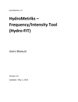
Practical Guide to
Inspection, Testing
and Certification
of Electrical Installations
I would like to dedicate this book to all of my grandchildren and
thank them for leaving me in peace when asked.
Practical Guide to
Inspection, Testing
and Certification
of Electrical Installations
Third Edition
Christopher Kitcher
Third edition published 2013
by Routledge
2 Park Square, Milton Park, Abingdon, Oxon OX14 4RN
Simultaneously published in the USA and Canada
by Routledge
711 Third Avenue, New York, NY 10017
Routledge is an imprint of the Taylor & Francis Group, an informa business
© 2013 Christopher Kitcher
The right of Christopher Kitcher to be identified as author of this work
has been asserted by him in accordance with sections 77 and 78 of
the Copyright, Designs and Patents Act 1988.
All rights reserved. No part of this book may be reprinted or reproduced
or utilised in any form or by any electronic, mechanical, or other means,
now known or hereafter invented, including photocopying and recording,
or in any information storage or retrieval system, without permission in
writing from the publishers.
The publisher and author disclaim any liability, in whole or in part, arising
from information contained in this publication. The reader is urged to
consult with an appropriate licensed professional prior to taking any
action or making any interpretation that is within the realm of a licensed
professional practice.
Trademark notice: Product or corporate names may be trademarks or
registered trademarks, and are used only for identification and
explanation without intent to infringe.
First edition published by Newnes 2007
Second edition published by Newnes 2008
British Library Cataloguing in Publication Data
A catalogue record for this book is available from the British Library
Library of Congress Cataloging-in-Publication Data
Kitcher, Chris.
Practical guide to inspection, testing, and certification of
electrical installations / Chris Kitcher. -- 3rd ed.
p. cm.
1. Buildings--Electric equipment--Inspection--Handbooks,
manuals, etc. I. Title.
TK4001.K48 2012
621.319'240288--dc23
2011035997
ISBN 13: 978-0-08-096907-7 (pbk)
Contents
List of figures and tables
Acknowledgements
Chapter 1
Chapter 2
Chapter 3
xi
xv
Introduction
1
Inspection and testing of electrical installations
1
The legal requirements
5
BS 7671
Building Regulation Part P
Section 1. Design, installation, inspection and
testing
Section 2. Extensions, material alterations and
material changes of use
Section 3. Information about other legislation
Compliance with Building Regulations Part P
Earthing and bonding to comply with Part P
Registered domestic installer
Unregistered competent person
DIY installer
Summary
6
6
8
8
9
10
10
11
11
12
Types of certification required for the
inspecting and testing of electrical
installations
13
7
Certification required for domestic installers (Part P)
Minor electrical installation works certificate
Part P domestic electrical installation certificate
Periodic inspection, testing and reporting
Certification required for the inspecting and testing
of installations other than domestic
Minor electrical installation works certificate
Electrical installation certificate
13
13
13
14
Initial verification inspection
21
Initial verification testing
Sequence of tests
Periodic inspection
Extent and limitations
Visual inspection
23
23
23
24
25
15
15
15
vi
Contents
What are we looking for during a periodic
inspection?
Three phase circuits/systems
Chapter 4
Chapter 5
35
39
Periodic testing
41
Voltage drop in conductors
Testing of electrical installations
Safe isolation
Safe isolation procedure
Testing of protective bonding conductors
Main protective bonding
Continuity of protective supplementary bonding
conductors
Determining if a metal part is extraneous or just
a piece of metal
Continuity of circuit protective conductors
Method 1
Method 2
Ring final circuit test
Broken conductor in a ring circuit
Interconnections
Polarity
Insulation resistance test
Low insulation resistance
Testing the whole installation
Testing of individual circuits
Surge protection
Insulation resistance testing of a 3 phase
installation
Polarity test
Polarity test on a radial circuit such as a cooker
or immersion heater circuit
Polarity test on a lighting circuit
Live polarity
44
46
46
49
53
53
Earth electrode testing
Measurement using an earth electrode tester
Performing the test
Testing with an earth loop resistance tester
Earth fault path for a TT system
Earth fault path for a TN-S system
Earth fault path for a TN-C-S system
Performing a Ze test
Circuit earth fault loop impedance Zs
Verification of Zs values
Method using tables from GN3 or the On-site
Guide
61
66
66
67
69
70
71
72
72
80
81
82
88
89
91
96
96
97
103
105
105
105
109
112
112
112
112
114
119
123
Contents
Direct measurement
A circuit incorporating a socket outlet on a ring
or a radial
Performing the test on a radial circuit other
than a socket outlet
Earth loop impedance using a high current loop
test instrument without tripping an RCD
Prospective fault current test (Ipf)
Enquiry
Calculation
Measurement
Three wire text
Functional testing
Residual current device
Types of RCD
RCDs and supply systems
Testing of RCDs
Voltage operated (ELCBs)
BS 4293 RCDs
BS EN 610081
BS 4293 type S
BS EN 61008 type S
BS 7288 RCD protected socket
BS EN 61009 RCBOs
Chapter 6
Completion of test certificates
Minor electrical installation works certificate
Part 1 Description of minor works
Part 2 Details of the installation
Part 3 Essential tests
Part 4 Declaration
Electrical installation certificate
Information required
Next inspection
Supply characteristics and earthing
arrangements
Nature of supply parameters
Frequency
Prospective fault current (Ipf)
External earth loop impedance (Ze)
Supply protective device
Particulars of the installation referred to in the
certificate
Main protective conductors
Main switch or circuit breaker
Comments on the existing installation
123
124
124
131
133
133
134
134
136
138
138
139
141
141
141
142
147
147
148
148
148
151
151
151
153
153
154
154
154
159
159
160
160
160
160
160
160
161
161
162
vii
viii
Contents
Chapter 7
Schedules
Schedule of test results
Information required
Test results
Schedule of inspections
Description of items to be checked
Basic protection
Fault protection
Prevention of mutual detrimental influence
Identification
Cables and conductors
General
Electrical installation condition report
Completing the form
Summary on the condition of the installation
Recommendations
Declaration
Schedules
Supply characteristics and earthing
arrangements.
Particulars of the installation referred to in the
certificate
Main protective conductors
Main switch/switch fuse/circuit breaker
Observations
Condition report inspection schedule
162
162
163
164
165
165
166
166
168
168
169
170
171
175
176
176
177
177
Correct selection of protective devices
185
Why are they installed?
What type of device is it? Is it a fuse or circuit
breaker?
Is the device being used for protection against
indirect contact?
What type of circuit is the device protecting, is it
supplying fixed equipment only, or could it
supply hand held equipment?
If it is a circuit breaker is it the correct type?
Will the device be able to safely interrupt the
prospective fault current which could flow in the
event of a fault?
Is the device correctly coordinated with the load
and the cable?
Additional information regarding circuit breakers
Overload current
Maximum earth fault loop impedance values
(Zs) for circuit breakers
177
179
179
180
180
181
185
186
187
187
187
188
188
188
188
188
Contents
Calculation of the maximum Zs of circuit
breakers
Comparing maximum Zs and measured Zs
Testing transformers
Step up or down double wound transformer
Isolation transformer
Separated extra low voltage transformers
(SELV and PELV)
Testing a 3 phase motor
Chapter 8
Test equipment
Instruments required
Low resistance ohm meter
Insulation resistance tester
Earth fault loop impedance tester
Prospective short circuit current test
instrument
Earth electrode resistance tester
Residual current device tester
Phase rotation
Thermographic equipment
Calibration of test instruments
Volt stick
Chapter 9
189
190
191
191
192
192
192
195
195
195
196
196
196
196
197
197
197
197
199
Electric shock
201
Ingress protection
203
Chapter 10 Testing photovoltaic systems
Testing and commissioning
Visual inspection
Testing the d.c. side of the installation
Insulation resistance test
Testing the a.c. side of the installation
205
205
205
208
216
219
Chapter 11 Exercises and questions
Chapter 12 Answers
223
239
Glossary
Index
263
269
ix
List of figures and tables
Figures
Figure 1.1
Figure 1.2
Figure 2.1
Figure 2.2
Figure 2.3
Figure 2.4
Figure 3.1
Figure 3.2
Figure 4.1
Figure 4.2
Figure 4.3
Figure 4.4
Figure 4.5
Figure 4.6
Figure 4.7a
Figure 4.7b
Figure 4.8
Figure 4.9a
Figure 4.9b
Figure 4.9c
Figure 4.10
Figure 4.11
Figure 4.12
Figure 4.13
Figure 4.14
Figure 4.15
Figure 4.16
Figure 4.17
Figure 4.18
Figure 4.19
Figure 4.20
Figure 4.21
Figure 4.22
Figure 4.23
Figure 4.24
Figure 4.25
Wind up insulation resistance tester
Earth fault loop impedance tester
Minor electrical installation work certificate
Electrical installation certificate
Schedule of test results
Schedule of inspections
Electrical installation condition report
Condition report schedule of inspection
Approved voltage indicator and test lamp
Warning notices
Locking devices
Proving unit
R1 + R2 box
Test line to neutral
Test line to earth
Neutral to earth
Locked off
Test line to neutral
Line to earth
Neutral to earth
Retest device
Double check
Isolate the supply
Bonding disconnected
Low resistance ohm meter
Lead connected
Second lead connected
Resistance value
Reconnect bonding
Incorrect!
Correct!
Lead touching tap
Lead on unpainted part of radiator
Fitting bonded across
Current flow through pipe
Cables joined
1
2
16
17
19
20
26
28
47
47
48
48
49
49
50
50
51
52
52
52
53
55
55
56
57
57
58
58
59
60
60
64
64
65
65
67
xii
List of figures and tables
Figure 4.26
Figure 4.27
Figure 4.28
Figure 4.29
Figure 4.30
Figure 4.31
Figure 4.32
Figure 4.33
Figure 4.34
Figure 4.35
Figure 4.36
Figure 4.37
Figure 4.38
Figure 4.39
Figure 4.40
Figure 4.41
Figure 4.42
Figure 4.43
Figure 4.44
Figure 4.45
Figure 4.46
Figure 4.47
Figure 4.48
Figure 4.49
Figure 4.50
Figure 4.51a
Figure 4.51b
Figure 4.51c
Figure 4.52
Figure 4.53
Figure 4.54
Figure 4.55
Figure 4.56
Figure 4.57
Figure 4.58
Figure 4.59
Figure 4.60
Figure 4.61
Figure 4.62
Figure 4.63
Figure 4.64
Figure 4.65
Figure 4.66
Figure 4.67
Figure 5.1
Figure 5.2
Probes on line and earth
Lead connected to earthing terminal
Lead touching earthed metal
Ring circuit
Broken conductor
Interconnection
Set to ohms
Test each end of the line conductor
Test each end of the neutral conductor
Test each end of the CPC
Cross connect live ends
Test line to neutral
Cross connect line to earth
Test line to earth at each socket
Cross connect live conductors
Conductors in series
Conductors in parallel
Leads apart
Leads together
Instruments set
Test between live conductors
Join live conductors and test to earth
Test between live conductors
Live conductors tested to earth
Test the set
Test L2 to L3
Test L1 to L3
Test L1 to L2
Link L1, L2 and L3
Test line to earth
Line and CPC connected
Test between line and earth R1 + R2
High reading
Line linked to earth terminal
Test between earth and switched line
Low reading
High reading
Line and earth terminal linked
Test at switch
Low resistance measure
High reading
Live supply
Live supply
No reading
Earth electrode tester
Electrodes in the ground
68
69
70
71
72
73
74
74
75
75
76
76
77
78
79
80
80
83
83
85
86
87
90
90
91
92
93
93
94
94
97
97
98
98
99
99
100
101
101
102
102
103
104
104
106
107
List of figures and tables
Figure 5.3
Figure 5.4
Figure 5.5
Figure 5.6
Figure 5.7
Figure 5.8
Figure 5.9
Figure 5.10
Figure 5.11
Figure 5.12
Figure 5.13
Figure 5.14
Figure 5.15
Figure 5.16
Figure 5.17
Figure 5.18
Figure 5.19
Figure 5.20
Figure 5.21
Figure 5.22
Figure 5.23
Figure 5.24
Figure 5.25
Figure 5.26
Figure 5.27
Figure 5.28
Figure 5.29
Figure 5.30
Figure 5.31
Figure 5.32
Figure 5.33
Figure 5.34
Figure 5.35
Figure 5.36
Figure 5.37
Figure 5.38
Figure 5.39
Figure 5.40
Figure 5.41
Figure 5.42
Figure 5.43
Figure 5.44
Figure 5.45
Figure 5.46
Figure 6.1
Figure 6.2
Tester connected
TT service head
TT fault path
TN-S service head
TN-S fault path
TN-C-S service head
TN-C-S fault path
Isolated
Disconnected earthing conductor
Test instrument
Line to earth
Line to neutral and earth
Certificate
R1 + R2 path
Measured value
Two lead connection
Three lead connection
Two lead connection
Three lead connection
Line and earth linked
Incoming supply to outgoing line
Instrument set
Test between incoming line and neutral
Measured value
Leads connected
BS EN 60898
Voltage operated RCD
BS 4293
BS 4293 type S
Single phase
Three phase
RCD socket outlet
BS EN 61009-1
BS EN 61008-1 type S
Set at times half
No trip
No trip
Test at times one
Test at 180°
Set at times five
Test at zero degrees
Test at 180°
Manual test
Test label
Minor works certificate
Electrical installation certificate
110
113
113
114
114
115
115
116
117
117
118
118
119
119
124
125
126
127
127
132
132
135
135
136
137
138
139
139
140
140
140
140
141
141
143
143
143
144
144
145
145
146
146
147
152
155
xiii
xiv
List of figures and tables
Figure 6.3
Figure 6.4
Figure 6.5
Figure 6.6
Figure 8.1
Figure 8.2
Figure 10.1
Figure 10.2
Figure 10.3
Figure 10.4
Figure 10.5
Figure 10.6
Figure 10.7
Figure 10.8
Figure 10.9
Figure 10.10
Figure 10.11
Figure 10.12
Figure 10.13
Figure 10.14
Schedule of test results
Schedule of inspections
Electrical installation condition report
Condition report inspection schedule
Test box
Calibration register
Transformer inverter
Inverter without transformer
D.C. identification
Dual isolation label
Commissioning report
Voltage measurement
Irradiance meter
D.C. clamp meter
D.C. leads joined
Current measurement using clamp meter
Current measurement using a multimeter
D.C. isolated
D.C. cables linked
Insulation test
157
158
172
182
198
199
206
206
207
208
209
211
214
214
216
217
218
219
220
220
Tables
Table 4.1
Table 4.2
Table 4.3
Table 5.1
Table 5.2
Table 5.3
Table 7.1
Table 9.1
Table 9.2
Table 10.1
Table 11.1
Table 11.2
Table 11.3
Table 11.4
Recommended tests for further testing
Maximum length of copper protective bonding
conductor
Minimum acceptable resistance values
Electrode resistance values
Ambient temperature multipliers
Examples of rated short circuit capacities for
devices
Circuit breaker application
Table of IP ratings
Third letter
Panel data sheet
Circuit details
Circuit details
Ring circuit detail
Zs values
43
54
81
111
121
138
190
204
204
211
225
226
229
231
Acknowledgements
Central Sussex College for the use of their workshop facilities
Simon Wood of Megger UK for help beyond the call of duty
Dave Chewter for always being ready to help with anything
Introduction
Inspecting and testing of electrical
installations
We all use electricity every day and most of us just take it for granted
that it is safe to use. Of course, for the majority of time it is. This is
not usually down to luck, although when I think about some of the
installations which I have seen over the years, I am well aware that on
some occasions luck must have been around in abundance.
Over the years the way we deal with electrical installations has
changed dramatically, this is of course down to education and
experience. Apart from the use of modern materials and methods of
installation we also have improved legislation in place which should
ensure that all installations are inspected regularly.
When I first stated full-time work back in the early 1960s, there
were massive house building projects being carried out all over the
country, but testing and certification of new installations was virtually
unheard of. When we had completed a new domestic installation, the
supply authority were really only interested in getting a signature from
the person who was going to be expected to pay the electricity bill
each quarter.
We used to do an insulation resistance test on the meter tails and the
person who installed the meter usually did the same before connection,
but that was all. The insulation resistance tester was not anywhere near
as sophisticated as a modern one, we used to have to wind the handle
of the instrument as it was a mini generator (Figure 1.1).
I remember clearly that if for some reason we had a fault due to a nail
being driven through a cable, or some other fault which resulted in a
bad reading, we would just remove the fuse wire from the rewirable
fuses, or disconnect the neutral of the circuit concerned before the
person arrived to install the meter. That way we could be sure that the
installation would be connected and that we would have an electrical
supply. It is usually easier to trace a fault if the system is live,
particularly in the winter, as it is much easier to find a fault in a warm
house with light than a cold house in the dark.
As far as earth fault loop impedance was concerned the only time we
measured that was when a survey was being carried out, and again
Figure 1.1 Wind up insulation
resistance tester
2
Introduction
Figure 1.2 Earth fault loop impedance tester
the instrument was entirely different to the equipment used today
(Figure 1.2).
All new houses had a copper or iron water main, as did most
old ones. As you can imagine, the surface area of the metal
from the water mains in contact with the soil was huge. This
resulted in very low earth fault loop resistance readings. This is
because the resistance of soil is usually very low as there is such a lot
of it.
As the years have passed more and more electrical equipment is
being installed into buildings; it is also becoming more and more
sophisticated of course. Health and safety, along with insurance,
has also had a hand in making it important that in the event of a fault
somebody can be held responsible. Usually this will be the person
signing the document to say that the installation is compliant with the
current edition of the wiring regulations (BS 7671). For this reason it
is very important that we take the installation of electrical wiring along
with inspection, testing and certification very seriously.
It is important that we not only know how to install all of our new
fixed wiring correctly, but that we know how to verify and document
it as well. Not only that! We should also be able to inspect an existing
installation and, with the help of some testing where required, we
should be able to verify that it is fit for continued safe use. Where
damage or non-conformities are found we must be able to identify
them and make sound, professional recommendations about the
installation.
Introduction
We must also be able to relay this information to our clients in a
professional, non-technical manner. Many of us will remember how
difficult it was to understand the terms used in the electrical industry
when we first started out.
Your client will need you to identify the technical detail, record it and
then relay it to them in words which they can understand, of course
before we can do that we need to understand it ourselves. Hopefully
what follows in this book will be of help.
Video footage and multiple choice questions are also available to
help you with this subject. Visit www.routledge.com/cw/kitcher to
access this material.
3
CH A P TE R
The legal requirements
Apart from the obvious safety reasons, we also have to concern
ourselves with the legal requirements for electrical installations. The
main statutory documents which we need to comply with are:
●
●
●
The Health and Safety at Work Act 1974 (HASWA)
The Electricity at Work Regulations 1989 (EAWR)
The Electrical Safety, Quality and Continuity Regulations 2002
(ESQCR).
The HASWA 1974 is in place to cover all aspects of safety at work
and can be viewed as the statutory document under which the other
statutory documents which involve health and safety sit. The EAWR
1989 are specific to electrical installations used in the work place,
although it is sensible for us to refer to them for all installations as this
will ensure an electrically safe environment.
Non-compliance with statutory regulations will be seen as a criminal
offence, and for that reason non-compliance could result in a very
large fine or even in some serious cases imprisonment, particularly
where the non-compliance has resulted in an accident.
The ESQCR are intended more for electrical supplies but do have
some effect on the daily activities of electricians, particularly with
regards to the positioning of consumer’s units and areas where TNC
systems are used. As an example, where an area is known to be
susceptible to flooding all of the supply equipment and consumer’s
units need to be sited above the expected flood level.
These statutory regulations not only apply to new installations, they
also apply to existing installations which have been in use for a
very long time. There is no age limit on electrical installations: the
requirement is that they are maintained in a safe condition and that
they remain fit for use.
Practical Guide to Inspection, Testing and Certification of Electrical Installations. 978-0-08-096907-7
Copyright © 2013 Christopher Kitcher. Published by Taylor & Francis. All rights reserved.
1
6
1
Practical Guide to Inspection, Testing & Certification of Electrical Installations
BS 7671
The most satisfactory way of ensuring conformance with statutory
regulations is to follow the requirements of the relevant British
Standard. The British Standard relating to an electrical installation is
known as BS 7671.
Within this set of standards Regulation 610.1 states ‘every installation
shall, during erection and on completion before being put into service
be inspected and tested to verify, so far as reasonably practicable,
that the requirements of the regulations have been met’. This
regulation of course applies not only to new installations, it also
applies to additions and alterations to existing installations.
The inspection and testing of new work is known as initial verification.
As the regulation suggests, this initial verification commences at the
same time as the installation work continues and carries on through
the duration of the job. The end result will be the issue of an electrical
installation certificate, along with the required schedule of test results
and a schedule of inspections, providing of course the work carried
out fully meets the requirement of BS 7671.
As we have seen previously the EAWR 1989 is not only for new
installations, if anything it is more relevant to existing installations.
BS 7671 Regulation 621.1 states that ‘where required, periodic
inspection and testing of every installation shall be carried out in
accordance with Regulations 621.2 to 5 in order to determine, so
far as is reasonably practicable, whether the installation is in a
satisfactory condition for continued service’.
Although BS 7671 is a non-statutory document it has been referred to
extensively in the Health and Safety Executive over a long period of
time. Regulation 114 also clearly states that although BS 7671 is nonstatutory it may be used in a court of law to claim compliance with a
statutory requirement.
It has been my policy over the years to explain as clearly as possible
to my students that although it is non-statutory, we all do ourselves a
big favour by pretending that it is statutory; this will ensure that we do
the best job possible and that all safety requirements are met.
Building Regulation Part P
The HASWA and EAWR both have the word work in them and of
course that reflects that they are intended for use in the work place.
However electricity is, or can be, a dangerous commodity wherever
it is used. It could also be argued that a domestic installation is a
The legal requirementss
place of work while the electrical installation is being carried out. This
means that the HASWA and EAWR are still relevant.
Domestic installations have been the subject of much discussion
over the years, mainly due to the upsurge in DIY. We all know that it
is reasonably easy to get something working, making sure it is safe
is often far more difficult. To try and get some kind of control over
this, the Building Regulation Part P was introduced and came into
effect on 1 January 2005; it was then amended on 5 April 2006. The
purpose of this document is to ensure electrical safety in domestic
electrical installations.
Section 1. Design, installation, inspection
and testing
This section of Part P is broken down into sub-sections.
General
This states that electrical work must comply with the Electricity at
Work Regulations 1989 and that any installation or alteration to the
main supply must be agreed with the electricity distributor.
Design and installation
This tells us that the work should comply with BS 7671 Electrical
Wiring Regulations.
Protection against flooding
The distributor must install the supply cut out in a safe place and
take into account the risk of flooding. Compliance with the Electrical
Safety, Quality and Continuity Regulations 2002 is required.
Accessibility
Part M of the building regulations must be complied with.
Inspection and testing before putting into service
This area is covered in detail throughout this book, it reminds us that
the installation must be inspected and tested to verify that it is safe to
put into service.
BS 7671 Installation certificates
This tells us that compliance with Part P can be demonstrated by
the issue of the correct electrical installation certificate. It also shows
what the certificate should cover. This is addressed later in this
book.
1
7
8
1
Practical Guide to Inspection, Testing & Certification of Electrical Installations
Building regulation compliance certificates or notices
for notifiable work
This tells us that the completion certificates issued by the local
authorities, etc. are not the same as the certificates that comply with
BS 7671. The completion certificates do not only cover Part P, but
also shows compliance with all building regulations associated with
the work which has been carried out.
Certification of notifiable work
This is covered in detail throughout this book.
Inspection and testing of non-notifiable work
This tells us that, even if the work is non-notifiable, it must be
carried out to comply with BS 7671 and that certificates should be
completed for the work.
Provision of information
Information should be provided for the installation to assist with the
correct operation and maintenance. This information would comprise
certification, labels, instruction and plans.
Section 2. Extensions, material alterations
and material changes of use
This section is covered throughout this book. It basically tells us that
certification is required, and that before any additions or alterations
are made to an installation, an assessment of the existing installation
should be made, to ensure that it is safe to add to.
Section 3. Information about other
legislation
This covers the Electricity at Work Regulations 1989; Electrical
Safety, Quality and Continuity Regulations 2002; and functionality
requirements.
The construction design and management regulations also state that
adequate electrical inspection and tests are carried out on all new
installations; those with electrical design information must form a
user’s manual, which can be used to provide an up-to-date working
record of the installation.
Due to the introduction of Part P even people who are not in the
electrical industry are becoming more and more aware that electrical
installations need to be safe. Insurance companies and mortgage
The legal requirementss
lenders are now frequently asking for certification as part of the
house buying and selling process. The owners and occupiers of
industrial and commercial properties are aware that the EAWR 1989
demand that they maintain a safe environment for people to work in,
while most licensing authorities and local authorities are asking for
electrical certification for most of the work with which they become
involved.
All of these regulations are under the umbrella of the Health and
Safety at Work Act 1974. This clearly puts the legal responsibility of
health and safety on all persons concerned.
Compliance with Building Regulations
Part P
Compliance with building regulations is a legal requirement and
electrical work carried out in the domestic sector is now included in
the building regulations; it is a criminal offence not to comply with the
building regulations.
At the time of writing, there is no legal requirement to notify any work
carried out in commercial or industrial buildings, although it should
still be certificated for safety and record-keeping purposes.
Approved Document Part P requires that most electrical work carried
out in domestic premises is notified to the local authority building
control. There are a few exceptions but the work must comply with
BS 7671 Wiring Regulations. The exceptions are as follows:
●
●
Minor works carried out in areas that are not classed as special
locations and therefore do not need notifying but would still need
certifying:
– addition of socket outlets and fused spurs to an existing radial
or ring circuit
– addition of a lighting point to an existing circuit
– installing or upgrading main or supplementary bonding.
Minor works carried out in the special locations as listed below
– or in kitchens (BS 7671 does not recognize a kitchen as a
special location. Part P does):
– kitchens
– locations containing bath tubs or shower basins
– hot air saunas
– electric floor or ceiling heating
– garden lighting (if fixed to a dwelling wall it is not deemed to
come into the special location category)
– solar photovoltaic power supply systems.
1
9
10
1
Practical Guide to Inspection, Testing & Certification of Electrical Installations
●
●
●
●
The work which could be carried out in these locations without
notification but should still be certificated would be:
Replacement of a single circuit which has been damaged
– providing that the circuit follows the same route
– the cable used has the same current carrying capacity as the
cable being replaced
– circuit protective measures are not affected.
Replacing accessories such as socket outlets, switches and ceiling
roses
Re-fixing or replacing of enclosures and components.
All other work carried out in any areas of a domestic installation must
be certificated and notified to the local authority building control, this
can be carried out by various methods.
Earthing and bonding to comply with Part P
If a minor electrical installation works certificate is necessary, there
is no requirement to upgrade the existing earthing and bonding
arrangements within an installation. Where the earthing and bonding
do not comply with the latest edition of BS 7671, it should be
recorded on the minor electrical installation works certificate and
brought to the responsible person’s or occupier’s attention.
If the work being carried out requires an electrical installation
certificate to be completed, then the earthing arrangements must be
upgraded to comply with the current edition of BS 7671.
Where the work is in a bathroom or any other areas which may
require protective supplementary bonding, then this must also be
brought up to the current standard.
There is no requirement to upgrade supplementary bonding in an
area where work is not to be carried out. There is also no requirement
under Part P to certificate the upgrading of any earthing and bonding
that has been carried out to an existing installation.
Registered domestic installer
To become a registered domestic installer, it is necessary to become
a member of one of the certification bodies which operate a
domestic installer’s scheme. This would require the person carrying
out the work to prove competence in the type of work which is being
carried out, and the ability to inspect, test and certificate the work
which he/she has carried out. Competence is usually assessed
by a site visit from an inspector employed by the chosen scheme
provider.
The legal requirementss
When the scheme was first introduced there were three types of
registration: A was for installers who could carry out all types of
domestic wiring, B for installers who only needed to install single
circuits in relation to the type of work which they were doing. This
could have possibly applied to a kitchen installer or a bathroom fitter.
Level C was for alterations and minor repairs only.
This has now changed and there is now one level of registration only
and that is full scope which allows anything from a change of switch
to a complete rewire or new installation
If the electrician is registered as a domestic installer, he or she must
complete the correct certification and notify the scheme provider,
with whom they are registered, of the work which has been carried
out. This must be done within 30 days. The scheme provider will both
notify the local authority and the customer of the correct certification
being given. An annual fee is usually required by the scheme provider,
while a small fee is also payable for each job registered.
Unregistered competent person
If the work is carried out by a non-registered competent person who
is capable of completing the correct certification, the local authority
will need to be contacted before commencement of the work, and
the work will be carried out under a building notice. This will involve
a fee being paid to the local authority and a visit or visits being
made by a building inspector to inspect the work being carried out
to ensure that it meets the required standard (the cost of this will
usually be far higher than that charged per notification by a scheme
provider to a registered installer). On satisfactory completion, and
after the issue of the correct certification by the competent person,
the building inspector will issue a completion certificate. The issue
of a completion certificate by the local authority does not remove
the responsibility for the work including guarantees from the nonregistered competent person; the required certification must still be
completed by the person who carried out or who is responsible for
the work.
DIY installer
In cases where the work is carried out by a person who could not
be deemed qualified (i.e. a DIY enthusiast), building control must be
informed prior to work commencing, and on completion of the work
to the building control officer’s satisfaction, an inspection and test
certificate must be issued. As a DIY installer would be unlikely to
have the knowledge, experience or correct test equipment required
1
11
12
1
Practical Guide to Inspection, Testing & Certification of Electrical Installations
to carry out the inspection, tests or completion of the certification,
the services of a competent person would be required. The qualified
person would in effect take responsibility for the new/altered work.
For that reason, the qualified person would need to see the work at
various stages of the installation to verify that the work and materials
used comply with the required standards of the BS 7671 Wiring
Regulations.
Summary
Currently, there is no requirement for any person carrying out
electrical work in a domestic environment to be qualified in any way.
The condition is that they must be competent; in other words, they
must be in possession of the appropriate technical knowledge or
experience to enable them to carry out the work safely.
Many organizations provide what are known as Part P courses;
however, it is not necessary to attend one of these in order to register
as a domestic installer. While it may well be beneficial to an electrician
who is a bit rusty to attend a refresher course just to ensure that they
are aware of the requirements of Part P, it is not possible to become
an electrician in 5 days!
You will even see advertised courses with duration of from 15 to
30 days, this is really just selling a dream, at the end of the period
you will have spent a lot of hard earned cash and collected a lot of
certificates. The one thing which you will not have is experience and
that is the most important tool which you could possibly have in your
box.
The building control authorities must be informed of any electrical
work that is to be carried out on a domestic electrical installation
other than very minor work, although even this work must be
certificated. Building control can be informed (before commencing
work) by the use of a building notice, and this will involve a fee.
If your work involves a lot of domestic electrical work, then by far
the best route would be to join one of the certification bodies. This
would allow you to self-certificate your own work. When you join one
of these organizations, you must be able to show that your work is
up to a satisfactory standard and that you can complete the correct
paperwork (test certificates). Whichever organization you choose
to join, they will give you the correct advice on which training you
require.
A qualification is fine, but being able to carry out electrical work safely
is far better: for that reason high quality training is very important.