1
Microelectronics – Systems and Devices
This Page Intentionally Left Blank
Microelectronics – Systems and Devices
Owen Bishop
OXFOR D
AUC KLAND
B OSTON
JOHANNE SB UR G
M E LB OUR NE
NE W DE LHI
Newnes
An imprint of Butterworth-Heinemann
Linacre House, Jordan Hill, Oxford OX2 8DP
225 Wildwood Avenue, Woburn, MA 01801-2041
A division of Reed Educacational and Professonal Publishing Ltd
A member of the Reed Elsevier plc group
First published 2000
© Owen Bishop 2000
All rights reserved. No part of this publication
may be reproduced in any material form (including
photocopying and storing in any medium by electronic
means and whether or not transiently or incidentally
some other use of this publication) without the
written permission of the copyright holder except
in accordance with the provisions of the Copyright,
Designs and Patents Act 1998 or under the terms of a
licence issued by the Copyright Licensing Agency Ltd,
90 Tottenham Court Road, London, England W1P 9HE.
Applications for the copyright holder’s written permission
to reproduce any part of this publication should be addressed
to the publishers.
British Library Cataloguing in Publication Data
A catalogue record for this book is available from the British Library
ISBN 0 7506 4723 X
Printed and bound in Great Britain
Contents
Preface
vi
Section A – The Hardware
1
2
3
4
5
6
Systems in action
The CPU
Memory
Inside the CPU
Interfacing
Planning the system
1
18
41
55
70
96
Section B – The Software
7
8
9
10
11
12
Instructions
High-level languages
Mnemonics
Input and output
Structured programs
Programming projects
107
122
133
145
168
193
Answers to questions
208
Index
211
Preface
This book is written for a wide range of pre-degree courses in
Microelectronic Systems. The contents have been carefully matched to
current UK syllabuses at Level 3, but the topics covered, depth of
coverage, and student activities have been designed so that the
resulting book will be a student-focused text suitable for the majority
of courses at pre-degree level around the world. The only prior
knowledge assumed is basic maths and science.
The UK courses covered by this text are:
•
•
Advanced GNVQ Units in Microelectronic Systems from Edexcel
BTEC National units in Microprocessor systems, MicroElectronic Systems, and Software Design Methods.
Essential theory is provided here but the book is strongly practical in
its approach, encouraging students to assemble and test real
microelectronic systems in the laboratory. The examination syllabuses
do not specify which processors and which programming languages the
student should cover. The suppliers’ catalogues list several hundred
microprocessors and microcontrollers and any one or more of these
could be selected as a subject for study. There is likewise a variety of
languages or versions of languages that may be used to program them.
To keep the size of the book within reasonable bounds, the book looks
at the Zilog Z80 as a typical microprocessor, and at the Atmel
AT90S1200 as a typical microcontroller. Both of these are readily
available from the major suppliers such as Farnell, RS Components
and Maplin, as well as from several of the smaller firms. Other
processors are mentioned where they show interesting differences from
these two types. With regard to languages, the book concentrates on
assembler (for the Atmel controller), BASIC and PBASIC (for the
Stamp). Other languages are described, including C.
The descriptions of these processors and languages are intended to
exemplify processors and languages in general. They are aimed at
giving the student a wide view of the topic, but it is not expected that
students will centre their studies on these particular processors or
languages. In keeping with the syllabuses, the book leaves the student
with an unrestricted choice of devices, prototyping systems and
programming languages.
The book is a study guide, suitable for class use and also for selfinstruction. The main text is backed up by boxed-off discussions and
summaries, which the student may read or ignore, as appropriate.
There are frequent ‘Test Your Knowledge’ questions in the margins
with answers given at the end of the book. Another feature of the book
is the placing of short ‘memos’ in the margins. These are intended to
remind the student of facts recently encountered but probably not yet
learnt. They also provide definitions of terms, particularly of some of
the useful jargon associated with microelectronics and computing.
Each chapter ends with a batch of examination-type questions, and in
most instances with a selection of multiple choice questions. Answers
to the multiple choice questions appear at the end of the book.
Owen Bishop
This Page Intentionally Left Blank
Systems in action
1
Part A – The Hardware
Systems in action
The essential features of a microelectronic system are described. These are illustrated by
descriptions of typical systems: a cordless telephone, programmable logic controllers in
industry, a personal computer, measuring instruments and data loggers, the control room of a
power station, and distributed processing in flight control of aeroplanes.
Microelectronic systems are digital systems, built from one or more
integrated circuits. They contain a central processing unit (CPU)
which is programmed to make the system perform its tasks. The CPU
is either a microprocessor or a microcontroller or, in complex systems,
there may be more than one. Microelectronic systems are widely used
in equipment and installations such as washing machines, automatic
teller machines, personal computers, production line packaging
machines, printing presses and radio-telescopes.
The CPU has such complicated tasks to perform that is is made up of
hundreds of thousands or even millions of transistors, as well as
resistors and other components, all assembled on the same silicon chip.
There are two main types of CPU:
•
•
Microprocessors
Microcontrollers.
2
Microelectronics – Systems and Devices
These have much in common, although there are important differences
between them. A microprocessor is just what its name says. It is a data
processor. It is designed to be able to process large quantities of
complex data at high speed. It needs the support of other units, such as
memory and input/output devices to make up a complete system. A
microcontroller usually operates more slowly and has less processing
capability but it has the advantage of having the other units on the same
chip. It is a ‘computer on a chip’ and, as such, is used on its own to take
full control of a piece of equipment or installation.
Because CPUs are programmable, the behaviour of the system can be
changed in many ways simply by revising the program. This gives
microelectronic systems a big advantage over hardwired logical
systems, such as are used in the less expensive home security systems,
the older types of washing machines, and in remote control systems.
Such systems may perform their intended task well but it is not easy to
alter the system once it has been wired. Any major change of action
usually involves rewiring, possibly changing some of the ICs and,
frequently, making so many alterations that it is simpler to scrap the
circuit and build a fresh one on a new circuit board. The flexibility of
microelectronic systems is one of the main reasons that they are so
widely used.
High and low
The two values that a digital quantity can take are often
referred to as high and low. A high value represents logical
high, which is equivalent to the binary digit ‘1’. A low value
represents logical low and is equivalent to the binary digit
‘0’. Some systems operate with the values the other way
round (negative logic) but this is very unusual.
In microelectronic circuits these values are represented by
voltages. Low is often represented by 0 V, or a value fairly
close to 0 V. High is often represented by +5 V, but other
values may be used in other types of microelectronic
system.
Note that, to a power engineer, high voltage means
something more than mains voltage, for example 450 V, or
even 132 kV. To a microelectronics engineer ‘high’ usually
means a mere 5 V. It is slightly higher in certain kinds of
system. However, high is just 3.3 V in the low voltage
systems that are intended for portable battery powered
equipment.
Systems in action
A survey
3
A simple system
Before we look in more detail at what what goes on inside a CPU, we
will take a few examples of the way microelectronic systems are used
in everyday life and at work. The cordless telephone is a typical
example (see over). As in any other microelectronic system, the circuit
centres on a CPU. In a cordless telephone this is a microcontroller,
complete with memory.
It may be wondered why a cordless telephone needs a CPU, yet an
old-fashioned corded telephone can operate without. One of the
reasons is that the corded telephone is wired directly to the public
network, but the cordless telephone has to make radio contact with its
base before a call can be received or made.
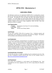
The handset of a cordless telephone (Fig. 1.1) consists essentially of a
radio transceiver that is under the control of a CPU. The radio has
limited range and communicates with the base unit, which may be up to
200 m away, normally in the same building. The base unit
Figure 1.1 A cordless telephone handset is under
the control of its central processing unit (CPU).
This may be a microprocessor or (more often) a
specialised microcontroller.
4
Microelectronics – Systems and Devices
Cordless telephones
Fig. 1.1 shows that the radio circuits are under the direct
control of the CPU.The double-headed arrow between the
CPU and radio circuits indicates that signals may pass in
both directions (though not both ways at exactly the same
time).
The radio circuits of the base station and the handset are
permanently switched on, waiting for a call. When the base
station receives an incoming call from the public network, it
sends out a digital signal by radio. This signal includes a
code that identifies the base station. The handset receives
this signal. However, it is also able to receive signals from
any other base stations within range. The signal is sent to
the CPU, which then checks to find out if this is the code of
its own base station. If it is not, it ignores it and nothing
further happens. If it is recognised, the CPU makes the
radio circuit send an acknowledging signal. The signal
includes a code to identify the handset. The base station
has been waiting to receive this signal, which is checked
by its own CPU to make sure that it comes from a handset
with which it is allowed to communicate. Then the CPUs
both open up the radio channels for two-way conversation
between the handset and the base, and by land line to the
remote caller.
The procedure is similar for an outgoing call. The CPU
makes the radio circuit transmit a series of code groups,
including its own identity code and the number to be
dialled. On confirming that the identity of the handset is
acceptable, the CPU of the base station dials the number.
In practice, dialling the number means generating a
sequence of pairs of DTMF tones that code the required
telephone number. When the number answers, it replies to
the handset and radio channels are opened for two-way
conversation.
The lower part of the diagram shows the input and output
that links the CPU to the user. The keypad is used to send
input to the CPU to tell it what number to call. It is also
used for operations such as storing frequently needed
numbers in memory. The CPU has output to one or more
signal LEDs that indicate when a call is in progress. It has
output to a separate IC which includes an oscillator to
generate the ringing tone.
Systems in action
5
communicates with the public telephone system through the
subscriber’s ordinary telephone line. The circuit of the base unit is
similar to that of the handset in many ways.
The operating system is stored permanently in a part of memory when
the telephone is manufactured. There is also a section of memory to
hold useful data, such as the number currently being dialled and a list
of frequently used telephone numbers. This data is changed from time
to time by the user.
A necessary part of any microelectronic system is the squarewave
generator known as the system clock. This provides the regular series
of pulses that drive the CPU. It is not shown in Fig. 1.1 because it is
usually included on the same chip as the CPU. The timing of the clock
usually depends on a quartz crystal, just as in a digital watch. There is
no room for the crystal itself on the CPU chip, so this is connected
across a pair of terminal pins of the IC. The frequency of the crystal
may be several hundred kilohertz or a few megahertz.
One of the essential outputs of a telephone is the ringing tone. It would
be possible for the CPU to be programmed to generate this tone itself,
but generating the tone would occupy the CPU at times when it could
more usefully be doing something else. It is common in
microelectronic systems to employ special-purpose ICs like this where
there are simple repetitive tasks to be done. The telephone has another
special IC to generate the DTMF dialling signal for transmission to the
base station.
Cellphones have circuits similar to cordless phones, the main
difference being that the cellphone communicates directly with the
public system through a base station up to several kilometres distant.
There is usually an LCD message screen to display numbers dialled
and other useful information.
Controllers in industry
Microelectronic systems are widely used in industry. This section
describes an example of microelectronic control of a chemical process
(Fig 1.2) by a programmable logic controller, or PLC. The CPU (with
system clock), its memory, keypad and display, are part of a single unit
(Fig 1.3). As in the telephone, the heart of the system is a CPU. This
has access to memory for storage of the program and working data. In
some systems the whole memory or part of it is included on the CPU
chip. There is often a keypad by which the operator runs the system,
and there is a message panel on which the CPU displays information
about the current state of the system.
6
Microelectronics – Systems and Devices
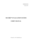
Figure 1.2 In the manufacture of chipboard, the bonding resin is
made by heating a mixture of urea and formaldehyde. A slider valve
(1) controls the flow of urea from a hopper (2) to the processing kettle
(3). The valve is opened or closed by a shutter that is moved by a
piston enclosed in a cylinder (4). The piston is moved by admitting
compressed air into the cylinder on one side of the piston or the other
side. The flow of air is controlled by two solenoid-operated air valves
(5 and 6), which are switched on or off by the microcontroller.
Proximity sensors detect when the valve is fully open (7) or fully
closed (8) and supply this information to the microcontroller.(By
courtesy of Kronospan Ltd., Chirk)
In the cordless telephone previously described, currents are small and
can usually be fed directly to the inputs of the CPU. Similarly, the
outputs of the CPU can provide sufficient current at the correct voltage
to drive logic circuits, including those driving display circuits and tone
generators. This is rarely the case in industrial plant. Motors often
operate on a 24 V DC supply or even run on alternating current at
mains voltage. Similarly, signals from sensors may be at voltages
higher than those acceptable by the CPU, and may sometimes be AC
signals.
Industrial sites are well known for generating strong electromagnetic
interference, so the input signals from sensors may carry high voltage
spikes. EMI may also be picked up by the output circuits and could get
back to the processor. For this reason, interface circuits (see Fig. 5.1)
are needed, both on the input and output sides to provide a lowvoltage, low-current, electrically ‘quiet’ environment in which the
CPU can operate reliably.
Systems in action
7
A Seimens 95U PLC can be seen in Fig. 1.4. The PLC is wired to a
number of input and output interfaces which are mounted on the rack
in the cabinet. Cables run from these to the sensors and actuators on the
plant. A few others run to control switches and indicator lamps on the
door of the cabinet. The door is normally closed when the plant is
operating, so acting as a control panel.
The program of a PLC runs continuously in a loop for as long as it is
switched on. The first stages of the program read the state of each
sensor and store the results in a special area of memory. Then the
program examines the input data and decides what action is to be
taken. As an example, take the valve mechanism of Fig. 1.2. If the
proximity sensor (7) shows that a shutter has reached the far end of its
travel, the valve (5) admitting compressed air to the nearer side of the
cylinder must be closed. A message indicating ‘close valve’ is stored in
the output area of memory of the PLC. When all the logical decisions
have been taken and the future output state is stored in memory, the
program reaches its third and final stage. It sends the stored output data
to the actuators. The actuators are switched on or off in response to the
latest state of the system. The program repeats immediately, so it is
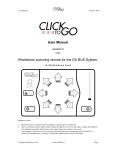
Figure 1.3 Like almost every other control system, a PLC is centred
on a CPU. The dotted line indicates that the CPU, memory, keypad
and display are normally installed as a single general-purpose unit.
Interfaces to sensors and actuators may be separately installed, and
there may be several hundred in the system. Smaller systems may use
PLCs with a dozen or so built-in interfaces.
8
Microelectronics – Systems and Devices
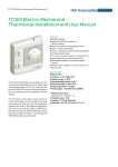
Figure 1.4 A PLC system is housed in a cabinet, shown here with the
door open. It controls the resin production plant illustrated in Fig.
1.2. The PLC controller is the small box mounted at the top left of the
cabinet, with its control keys situated below its LED display. The lowvoltage power supply is mounted to the right of the PLC. The input
and output interface units are mounted on the rack below the PLC.
Each may be connected to up to eight sensor or actuator devices. On
the right is a laptop PC being used for writing programs and
downloading them into the PLC. (By courtesy of Kronospan Ltd.,
Chirk)
Controlling a chemical reaction
The use of PLCs in industry is illustrated by a stage in the
manufacture of urea-formaldehyde resin (Fig. 1.2). There
are several factors that determine whether the shutter
should be opened or closed. For example, the shutter
must be opened when the process begins, and must be
closed when the kettle is full. Weighing sensors tell the
CPU how much urea has been added to the kettle. Mixing
urea with formaldehyde causes heat to be generated so a
thermal sensor provides essential input to the CPU. The
rate of addition of urea must be carefully controlled so that
it does not overheat. The CPU controls another actuator
which is a water valve which admits cold water to pipes
surrounding the kettle. The program continually checks
temperature and adjusts the rate of addition of urea and
the rate of flow of cooling water accordingly.
Systems in action
9
continually reading input from the sensors, taking decisions and
sending the appropriate output to the actuators. A typical program has
a few hundred or thousand steps and take only a few tens of
miliseconds to run, so the system responds reasonably quickly to
changes in the state of the inputs.
The example of the valve demonstrates that it is not enough for the
CPU to instruct actuators to move the shutter. There must also be
sensors to check that the shutter is actually open or shut. This is to
allow for the fact that it may not have had time to move to the required
position. Or maybe it has jammed.
A system of the kind shown in Fig. 1.3 is common in industrial plant,
whether it is a simple machine for filling cartridges with toner powder,
a vast printing press, or a chemical plant producing insecticides. The
main difference from one system to another is in the types and numbers
of sensors and actuators attached to the system. The other main
difference is the program that directs it. The program for the PLC is
written by the operator, using special software running on a
microcomputer. The PLC in Fig. 1.4 was in the process of being
programmed by the laptop PC on the right. The program is tested on
the microcomputer and, when it is free from bugs, downloaded into the
memory of the PLC. Once the program is running correctly, the PC is
disconnnected from the system and the PLC runs independently. The
program is not normally altered except when there is to be a change in
the operating procedure of the plant.
PCs and similar computers
There is much to be said about computer systems in later chapters, so
for the present we will simply state the main ways in which they differ
from the typical microcontroller systems described above. In essence,
all computers have the same main features and we may take the typical
personal computer (PC), as our example (Fig. 1.5).
The basic features are the same as in any microelectronic system: CPU,
memory, input and output. Because the PC is intended to perform a
wide range of often complex operations at high speed, a
microprocessor is chosen as its CPU. Usually the system clock is a
separate unit, as shown in Fig. 1.5. In contrast to systems such as the
cordless telephone and PLCs, the PC has a full-sized keyboard, with
over a hundred keys. It normally has a colour monitor.
The PC has several other input and output units either built into it or
connected by special sockets. These include disk drives of various
kinds, a mouse, and a printer. There may also be other devices such as
10
Microelectronics – Systems and Devices
Figure 1.5 This simplified diagram of a PC shows that it has much in
common with the typical control systems of Figs. 1.1 and 1.3.
a pair of loudspeakers, a joystick, a scanner and a digital camera.
One of the distinctive features of a PC and other computer-like systems
is the bus. To assist the rapid transfer of data between the CPU and the
other parts of the system the units are linked by a set of parallel
conductors, shown for simplicity as a single conductor in Fig. 1.5. In
practice, the bus consists of three separate busses, each with its own
task, as will be explained in Chapter 2.
A PC is programmed from various sources. First of all, it has a block
of permanent memory in which the operating system is stored. It has
numerous programs stored on its disk drives, and the user can purchase
other programs on compact discs, or download them from the Web.
These programs are temporarily transferred to the computer’s memory
when they are to be run. Programs include word processors,
spreadsheets, accounts programs, games, educational and training
programs, and information programs such as dictionaries,
encyclopaedias, telephone directories, catalogues and atlases. A wide
range of specialised programs is obtainable for use by travel agents,
theatre booking agents, medical centres, libraries and other medium
Systems in action
11
sized organsations. Major businesses and organisations such as banks
and oil companies employ software writers to produce programs
intended for their operations (Fig. 1.6).
Figure 1.6 Using a mouse to control a power station. The state-ofthe-art control room at Ironbridge Power Station, Shropshire, uses
computer monitors to display data readings taken at dozens of points
in the steam-producing plant, in the turbines and in the electricity
generators. The operator controls the power station by calling up a
virtual control panel on the monitor. On this, the usual control
switches, variable resistors, indicator lamps and meters are displayed
in diagrammatic form. There is no keyboard on the computer.
Instead, the operator uses a mouse to operate the controls, clicking
on ‘buttons’ or dragging ‘sliders’ in just the same way as when
playing a computer game. The station also has a basic conventional
control panel with real switches for back-up in case of computer
failure. (By courtesy of Eastern Generation Ltd.)
Measuring instruments
Except in the cheapest models, the circuit of a digital multimeter (Fig.
1.7) centres on a microcontroller. This makes it possible for the
multimeter to perform a range of functions quite beyond the scope of
the conventional analogue multimeter, based on a moving-coil
12
Microelectronics – Systems and Devices
microammeter. The user of the digital meter simply selects what
quantity is to be measured, applies the two probes to two test points in
the circuit, and the reading automatically appears on the display. It is
automatically updated several times per second. The display usually
consists of 4 digits, with a movable decimal point and a polarity
indicator (− for negative values). The quantities that can be measured
include voltage, current, resistance, capacitance and frequency. With
an ordinary multimeter the user has to select the range, but range
selection is automatic with a meter based on a microcontroller.
Figure 1.7 A multimeter is no longer a switched network
of resistors and capacitors connected to a sensitive
moving-coil microammeter. It still has the resistor and
capacitor network, but now most of the switching is done
by CMOS gates managed by a microcontroller.
Systems in action
13
Given a constant current source, a timing circuit and a voltagemeasuring circuit, it is possible to measure all the other quantities.
Resistance can be measured by finding the voltage drop across the
resistor when a given current flows through it. Capacitance can be
measured by finding how long it takes a constant current to charge the
capacitor to a given voltage. Frequency can be measured by timing the
changes in voltage. These tests are easily automated for different
ranges.
One of the few disadvantages of the numeric display of a digital meter
is that, with a varying quantity, the rapidly changing figures do not help
the user to visualise the way in which the value is changing. The needle
of the conventional electromagnetic meter is much better for this
purpose. The multimeter makes up for this with a bargraph display,
which can be seen running along the lower margin of the display in Fig.
1.7.
The meter can also process the measurements. If the meter is run for a
few minutes or more, the user can view the values as they change, or
the microcontroller can be programmed to pick out the maximum
value and the minimum value, and to calculate and display the
difference between maximum and minimum, and the average value. It
can also measure the voltage produced by a thermocouple and
calculate the equivalent temperature in Celsius or Fahrenheit.
The next grade of microelectronic instruments above the multimeter is
the data logger. In practice, these instruments perform two related but
distinctive tasks:
•
•
Data acquisition – receiving data (voltages, counts) from sensors.
Data logging – recording data and processing it.
The Datataker (from Data Electronics), upon which this descripton is
based, acquires measurements from a number of sensors connected to
its array of input terminals. The measurements may be displayed on the
Datataker’s own screen or on the monitor of an attached computer.
Subsequently the data can be stored (logged) in its own memory or on
removable memory cards. The data can then be processed. For
example, the device can calculate maxima, minima and other functions.
It can also convert voltage, for example, into temperature in Celsius or
Fahrenheit. The Datataker is able to perform its calculations at a higher
level than the multimeter. For example, it has selectable routines for
different types of thermocouple instead of being restricted to the one
type supplied with the instrument. The scope of processing is increased
by including statistical operations such as calculating standard
deviations and plotting histograms. There are many other refinements
in data presentation. For instance, each measurement is ‘time and date
stamped’ with the time and date at which it was taken.
14
Microelectronics – Systems and Devices
Another major bonus of the data logger is that it is programmable. It
can be set to take periodic readings from a number of different sensors
and store the results for display later. Or it may be set to produce an
alarm output when values fall in a specified range. The data logger is
programmed by using word-processing software running on a PC. It
has its own specialised programming language. The finished program
is downloaded from the PC into the Datataker. This can then run the
program on its own, when it is no longer attached to the computer.
Distributed processing
In a conventional microelectronic system the CPU has direct control
over all the input and output devices in the system. Figs. 1.1, 1.3 and
1.5 show examples of this. Now that a wide range of microcontrollers
is available cheaply, a new approach to control has become more
widespread. Each sensor or actuator in the system has its own
microcontroller as an integral part of it. The microcontroller is
programmed specifically to manage the action of the sensor or
actuator. For example, consider an electric motor geared to an aileron
in the wing of an aeroplane. When the aileron is to be moved, a
command is sent from the central computer in the pilot’s cockpit to the
controller in the wing. The controller is then responsible for moving
the aileron to its new angle. Normally it will accelerate it as fast as
mechanical stresses allow until it reaches the maximum allowable rate
of turning. This controlled acceleration involves complicated
calculations by the microcontroller, based on previously determined
parameters. There must be feedback of the actual position of the
aileron to allow for mechanical effects such as wind resistance.
The controller has been told the angle at which the aileron is to finish
so, before it reaches that position, the controller begins to decelerate it
at the maximum allowable rate so that it finally comes to rest at
exactly the required angle. While the action is in progress and when it
is completed the processor reports back to the main computer. The
main computer may also interrogate it at any stage to find out what
angle the aileron has reached.
This is a reasonably complicated operation in which factors such as
wind resistance must be taken into account. It is simpler for the task to
be undertaken by an independent processor situated at the motor, than
it is for all the ailerons and other control surfaces to be controlled from
the central computer. In addition, this approach requires less cabling
and is less subject to electromagnetic interference.
Distributed processing is part of the new ‘fly by wire’ principle
adopted by Lucas Aerospace, as used in the A320 ‘Airbus’ aeroplane.
Systems in action
15
Summing up
Microelectronic systems may be divided into::
•
Control systems – examples: resin production, flight controls,
automotive applications.
•
Instrumentation systems − examples: testmeters, data acquisition
and data logging.
•
Communications systems − examples: cordless telephone,
facsimile machine.
•
Commercial systems – example: personal computer, automatic
teller machine, EFTPOS station, stock logger.
AActivity 1.1 Microelectronic systems
Find out as much as you can about a machine or
equipment that is based on a microelectronic system.
Examples include:
Washing machine
Fax machine
Telephone answering machine
Dot-matrix printer
Stock logger
‘Smart’ room heater
Compact disc player
Garden or greenhouse reticulation (watering) system
Car park entry and exit control
EFTPOS machine (Electronic fund transfer at point of
sale)
ATM (Automatic teller machine, also known by other
names such as cash dispensers)
Global positioning system device
Radar systems (including radar speed traps)
Traffic control systems
Car engine control
Robotics
Sources of information are:
Books in the public library and your departmental library
Back issues of technical periodicals
16
Microelectronics – Systems and Devices
Manufacturers’ advertising matter and brochures
Manufacturers’ and other sites on the Internet
Arranged visits to local factories and businesses
Problems on
systems in
action
1 List the stages in making a call from a cordless phone, referring to
the parts of the system that are pictured in Fig. 1.1. Cover the action
from the time the handset is switched on until the first words are
spoken.
2 Outline the structure and action of a programmable logic controller.
3 Explain why special interfaces are needed between a PLC and the
attached sensors and actuators.
4 Describe the sequence of actions as a PLC runs its program.
5 In what ways does a digital multimeter based on a microcontroller
differ from an analogue multimeter with a moving-coil microammeter?
What are the advantages of the digital multimeter?
6 List the devices (peripherals) that may be attached to a PC and
explain briefly what they do.
7 Describe the features and action of a data logger.
8 What is meant by distributed processing?
9 Write an essay under the title ‘Microelectronic systems in everyday
life’.
Multiple choice
questions
1 Lamps, motors and solenoids are examples of:
A
B
C
D
sensors.
interfaces.
actuators.
outputs.
A
B
C
D
a microelectronic system.
the heart of a microelectronic system.
unit which stores a program.
a computer on a chip.
2 A CPU is:
3 When a PLC is running its program it is directly connected to:
A
B
C
D
sensors.
actuators.
a PC.
interfaces.
Systems in action
4 A microcontroller:
A
B
C
D
has its CPU and memory on the same chip.
has only a CPU on its chip.
controls a PC.
is designed to process data at high speed.
17
18
Microelectronics – Systems and Devices
The CPU
The controlling centre of a microelectronic system is its central processing unit or CPU. A
typical microcontroller, the Atmel AT90S1200, and a typical microprocessor, the Zilog Z80, are
examined in detail, and compared with other popular units of the same type. The architecture
of microcontroller systems is compared with that of microprocessor systems. The bus of
microprocessor systems is seen to comprise a data bus, an address bus and a control bus.
The functions of each are described. In connection with the data bus, the purpose of three-state
outputs is described. Discussion of the address bus centres on address decoding. The
functions of the signals on the control bus of the Z80 are explained. The system clock
co-ordinates the activities of the CPU and the other units in the system.
As we have seen in Chapter 1, a microelectronic system has a number
or fairly standard parts:
•
•
•
•
•
the CPU.
the system clock.
conductors for carrying signals between the CPU and the other
parts of the system.
memory, of various kinds.
an assortment of input and output circuits and devices, mainly
depending upon the application.
The controlling centre of a microelectronic system is the CPU. Its
function is to read data from certain parts of the system, to act on it
The CPU
19
(process it) and to output the results. As explained in Chapter 1,
microcontrollers differ in several ways from microprocessors, so we
consider them separately. There are several hundreds of different
microcontrollers and microprocessors. In this chapter we consider a
few typical examples.
Microcontrollers
As our first example of a CPU, Fig. 2.1 shows a commonly used
microcontroller, the Atmel AT90S1200, which we shall refer to as the
‘1200’ for short. Remember that this is a complete system on a single
chip so its use of terminal pins (its pinout) is very different from that of
the microprocessors that we describe later. This simplicity is what
makes systems based on microcontrollers so much easier to design and
build. The terminal pins fall into four main groups:
•
•
•
•
power lines − the positive (VCC) and 0 V (GND, short for ground)
lines connect to these pins. The voltage between them should be in
the range 2.7 V to 6 V.
crystal − the system clock circuit is inside, except for the crystal,
which must be connected across these two terminals, XTL1 and
XTL2. The maximum crystal frequency is 16 MHz.
I/O ports − there are two of these, port B and port D (larger 40-pin
members of this series also have ports A and C). Port B has 8 pins,
PB0 to PB7, while port D has only 7 pins, PD0 to PD6. The ‘bits’
of each port (the individual pins) can be programmed as inputs or
as outputs.
reset − this line is held high when the CPU is running. A low level
(0 V) on this line resets the system.
Figure 2.1 The pinout of the 1200 illustrates the way we number
the pins of ICs when there is a row of them down each side of the
IC. As viewed from above (pins pointing down to the circuit board)
pins are numbered from 1 down the left side, continuing up the right
side. A notch indicates the end of the IC where pin 1 is located.
Some makers mark this end with a dot or a stripe instead.
20
Microelectronics – Systems and Devices
Numbering digits
When a number consists of more than one digit, they are
numbered from right to left, starting with number 0. For
example, in the number 5239, D0 is ‘9’, D1 is ‘3’, D2 is ‘2’
and D3 is ‘5’. D0 is always the least significant digit (LSD).
In a 4-digit number, D3 is the most significant digit (MSD).
In the ‘1220’ IC (Fig. 2.1) the eight terminals of port B are
numbered from PB0 (LSD) to PB7 (MSD), using the same
rules.
Parallel and serial data
Digital data are transferred from one place to another
either in parallel or in series.
Serial transfer (Fig 2.2) requires only one line, along which
the voltage levels are sent one after the other.
In parallel transfer (Fig. 2.3), a binary number is
represented by high and low voltages placed on a set of
conductor lines at the same time. Transfer requires a
separate line for each bit.
Parallel transfer is quicker but requires more tracks on the
circuit board, more terminals on the ICs and may require
more buffers at each stage to relay the signals. It is used
inside computers and other data-processing equipment
(such as modems) to provide speed. In contrast, serial
transfer needs only one track, one terminal and one buffer
at each stage, but it is much slower. It is often used for
communicating between microelectronic systems,
particularly by the telephone system or by radio links,
where only one channel is available.
Figure 2.2 Serial transfer of a byte of data uses only one
data line but takes about 8 times as long as parallel transfer.
The CPU
21
Figure 2.3 Parallel transfer of 1 byte (8 bits) of data
requires 8 data lines, D0 to D7.
In order to keep the size (or more exactly, the number of pins) of the IC
reasonably small, manufacturers often allocate two or more functions
to the same pin. In the instance of the ‘1200’ the I/O pins PB5, PB6
and PB7, together with the RESET pin, can also be used as a serial port
for downloading a program from a computer (such as a PC) to the
memory inside the ‘1200’. In serial transfer of data, high or low pulses
are fed into or out of the pin one after another (Fig. 2.2).
It can be seen that the pins of the ‘1200’ provide all the essential access
to the system: a power supply, a timing crystal (too big to go on the
chip), a way of quickly resetting the system, and connections for
sensors and actuators for inputting or outputting data.
Data can be fed to the ‘1200’ in parallel (Fig. 2.3). That is, we
simultaneously send a ‘1’ or ‘0’ along its 8 Port B lines and so load it
with 8 bits (a byte) of data in a single operation. We can do the same
thing with Port D, except that this has only 7 bits. Similarly, we can
read (in parallel) a byte from Port B or a 7-bit group from Port D.
As might be expected from their name, microcontrollers are mainly
used in control applications. A port may receive a byte of data from a
temperature sensor, the value of the byte representing the temperature.
In the other direction, the port may output a byte of data to control the
speed of a motor. However, the input from a sensor may not be a byte
but a single bit.
22
Microelectronics – Systems and Devices
Other controllers − the PIC family
The Microchip PIC family of microcontrollers has many
and varied members. Some of the smallest are in a
standard 8-pin IC package (Fig. 2.4). The 12CE518 runs
on 2.5 V to 5 V, with a frequency up to 4 MHz. It has a
program memory (PROM or EPROM) of 512 bytes. It also
has 25 bytes of RAM and 16 bytes of EEPROM, which can
retain stored data for as long as 40 years.
Programs are loaded serially and there are six I/O pins.
Members of this family are RISC processors. The
12CE518 has only 33 instructions in its set, so learning to
program it does not take long. All of its instructions except
branches take 1 μs to execute. Branches take 2 μs.
It has a built-in timer that can function as a real time clock.
It also has a watchdog timer that has its own oscillator to
ensure reliability.
Another RISC (35 instructions) microcontroller is the
16F872, which is typical of the more advanced members
of the PIC family. It is in a 28-pin package, which allows it
to have three I/O ports that are 6, 8 and 8 bits wide. It runs
at 20 MHz. It has 2K × 14 words of FLASH
reprogrammable program memory, 128 × 8 bytes of RAM
and 64 × 8 bytes of EEPROM. On the same chip there are
three timers, a watchdog timer with its own oscillator, a 10bit analogue to digital converter, a synchronous serial port.
It can be programmed to capture a 16-bit value at regular
intervals, which gives it application in data acquisition. The
captured data can be compared with a value in another
register and produce an output signal if the two are equal.
There is also a pulse width modulator to generate pulses
of a set length. In total, this is a very versatile controller
with many applications in control systems and
measurement systems.
There is a wide range of development equipment and
software to help the PIC programmer. These include
assembler programs and software for programming in the
C or BASIC languages. The Stamp 2 is a complete
microcontroller system based on the PIC16C57. It includes
a compiler for PBASIC, which is a version of BASIC
devised for making best use of the features of the 16C57.
Some programs for the Stamp 2 are provided later in this
book.
The CPU
23
Figure 2.4 The smaller PIC microcontrollers have only 8 pins.
Some pins share several functions.
Example:
In an industrial plant, either a valve is closed or it is not closed.
The sensor is a microswitch on the valve, which closes when the
valve is closed. The signal is sent from the microswitch to one
of the port pins of the CPU. It is a high voltage (logic 1) when
the valve is closed and is a low voltage (logic 0) when the valve
is not closed. The signal is a single bit.
Example:
Either the temperature of a vessel has reached the required level
or it has not. We can represent these conditions by input from a
thermal sensor at just one pin of Port B. The input is high when
the temperature has reached the required level and is low when
it has not. Again, the signal is a single bit.
The same applies to many actuators. If a motor is either running or not
running, only a single bit is required to switch the motor on (1) or off
(0). For this reason, the individual bits of each port may be configured
as inputs or outputs, and the output and input values set individually.
On the ‘1200’ we could have up to eight different sensors, or eight
different actuators (or a mixture of both) connected to Port B and
seven more connected to Port D.
When it is important to keep the size of the IC (and therefore the
number of pins) to a minimum, it is possible to transfer data serially
into or out of the microcontroller. Then we need only a single input/
output pin. An example of this is seen in the ‘1200’ microcontroller. In
programming mode, the pin PB5 (see Fig. 2.1) is used for serial input
of programs. Pin PB6 is used for serial output, when the program is
read back into the programming PC to verify it. PB7 is used as a clock
input for the serial data transfers. The main disadvantages of serial data
transfer are that it takes longer than parallel transfer does and that the
programming is more complicated.
24
Microelectronics – Systems and Devices
The layout of a typical microcontroller system is represented in Fig.
2.5. The input devices may be directly connected to the I/O pins.
Switches for example, can be wired directly to the IC as in Fig. 2.6.
Figure 2.5 A microcontroller has the CPU and most other units of
the system on a single chip. It communicates with the external world
through the I/O pins of its one or several ports. The input and output
lines radiate from the microcontroller.
Figure 2.6 A simple one-bit
input to a microcontroller. The
resistor holds the pin high (logic
1), except when the switch is
closed, when the input is low
(logic 0). A suitable value is
10kΩ. Note that +V is the
processor supply voltage.
The CPU
25
Figure 2.7 Simple one-bit control of a
filament lamp by a microcontroller.
The resistor limits the current drawn
from the output pin to a safe level. +V
may be higher than the processor
supply voltage, if required.
Other input devices, such as photocells or Hall effect magnetic
detectors, need a simple circuit to interface them to the
microcontroller. Similarly, the pins of typical microcontrollers are able
to source a few tens of milliamps, so indicator devices such as LEDs
can be driven directly from the pins. Devices that will accept logiclevel inputs can also be driven directly. Other output devices, such as
solenoids and motors, require heavier currents and so need special
interface circuits, such as a switching transistor (Fig. 2.7).
The ‘1200’ is the simplest member of the AVR family of
microcontrollers. Others have larger on-board memory and additional
features such as a serial port, a pulse width modulator, capture/
compare circuitry and an extra timer.
Microprocessors
At one time, the Z80 was used as the CPU in several of the popular
hobby computers. It still has many applications in microelectronic
systems, particularly those that require more computing power than a
microcontroller is able to provide. However, as the CPU of hobby
computers and other desktop computers, it has been superseded by
much more powerful processors, such as the Intel Pentium and the
AMD Athlon.
The Z80 is contained in a 40-pin package. Its pins fall into seven main
groups:
•
•
•
power lines − the Z80, like most microprocessors and other
devices in the system, runs on a 5 V supply.
data inputs/outputs − there are 8 of these, allowing a byte of data
to be read or written by the IC.
address outputs – there are 16 of these, providing 64K (see box)
locations in address space. More advanced versions of the Z80
26
Microelectronics – Systems and Devices
•
•
•
•
such as the eZ80 have 24 address outputs.
system clock input.
reset input.
control inputs − there are six of these. The inputs control the rate
of processing or allow processing to be interrupted or slowed.
control outputs − there are seven of these, used by the CPU to
communicate with the rest of the system.
The internal structure and activities of the microprocessor are
described in Chapter 4. Here we look at the ways in which the
microprocessor communicates with the other parts of the
microelectronic system.
Architecture of the system
A microcontroller system usually has I/O connections radiating to the
input and output devices (Fig. 2.5). By contrast, a microprocessor
system has a single, central connector with branches going to the
microprocessor and all other units in the system. This arrangement of
connectors is known as a bus. The bus was first referred to in Fig. 1.5
but, in the more detailed drawing of Fig. 2.8, it can be seen that there
are actually three busses running side by side. Each bus is connected to
all the units of the system. The three busses are concerned respectively
with data, addresses, and control (match this statement with the list of
pin types in the previous section). Note that the data bus carries signals
from the CPU to other parts of the system and also carries signals to
the CPU from other parts. There is two-way communication. The
address bus and individual lines of the control bus communicate in
only one direction.
Figure 2.8 A typical microprocessor system has all its parts connected
to the data, address and control busses.
The CPU
27
Continual upgrading
The reader should be aware that the microelectronics
industry is forever active in producing new devices and
improving the performance of the old ones. It is impossible
for a book to be really up-to-date. Specifications can and
probably will change between the date this book is written
and the date that the reader gets it, even though the dates
are less than a year apart.
The best way for the reader to keep up-to-date is to study
the various electronic magazines and to browse the
electronic sites on the Internet.
Arrangements of pins
In the Z80, the terminal pins are arranged in two rows
along either side of the ICs, as in Fig. 2.1, except that
there are 40 pins (more in some versions). This is known
as the dual-in-line (DIL) layout. CPUs that are more
powerful have many more pins. This is mainly because of
extra pins in the data I/O and address output groups. The
extra data pins (bringing the total to 16 or 32) connect to
additional circuitry on the chip. They allow the CPU to deal
with much larger numbers and longer codes. The extra
address output pins allow the CPU to address a much
larger memory (see box, p. 30). The DIL layout is not
suitable for more than about 40 pins. ICs with larger
numbers of pins are usually square, with the pins arranged
along all four sides in a single or double row. The most
powerful CPUs, such as the Pentium and Athlon, have
hundreds of pins and special layouts are used.
The data bus and three-state outputs
If we look even more closely at a bus, we see that each bus consists of
many tracks running side by side. Fig. 2.9 shows a data bus that is eight
bits (1 byte) wide. This is typical of most microprocessors. Voltages
representing logic low (0) or high (1) are placed on this bus, by the
CPU or other devices in the system. They represent a number or an
operational code. This is how the CPU reads data from units such as
the memory, or sends data to units such as an output port.
28
Microelectronics – Systems and Devices
Figure 2.9 A bus consists of a number of conductors running side by
side on the circuit board. Here we illustrate a data bus that is 8 bits
wide. The figure shows the voltage levels on the data bus when the
binary value 1011 1001 is present.
One essential point about a data bus is that only one unit can be
allowed to place data on it at any one time. It is the same situation as a
discussion group. If one person is talking, the others must keep quiet so
that person can be heard by all. However, in all the units in Fig. 2.9 the
data output pins are permanently soldered to the bus. It is inevitable,
given the way in which microelectronic systems are constructed. The
difficulty is that, even if the outputs of the ‘quiet’ units are at zero
volts, they will pull the bus voltage levels down. The signal from the
‘talking’ unit will be ‘swamped’ by the 0 V levels from the ‘quiet’
units. The solution to this problem is for all units connected to the data
bus to have three-state outputs. The three states of such an output are:
•
•
•
logic 0 − the pin is at logic low voltage.
logic 1 − the pin is at logic high voltage.
the pin is in the high impedance state.
In the first two states the pin is electrically connected to the bus so that
the output voltage (high or low) of the internal logic circuit appears on
the bus. In the third state, a very high resistance is switched in, between
the pin and the internal circuit. The resistance (or impedance) between
the pin and the circuit is very high. In effect, the pin becomes
The CPU
29
Bus width
−
A typical microprocessor such as the Z80 has eight lines in
its data bus. We say the bus is eight bits wide, and we
number the bits from D0 (the LSB) to D7 (the MSB).
However, a bus with only 8 bits can transmit only the
integer values from 0 to 255. It takes more bits to
represent larger numbers or to represent quantities more
precisely. The main way to allow for larger numbers and
greater precision is to increase the number of bits to 16, 32
or (as in the case of the Intel Pentium and Digital Alpha)
to 64.
The number of lines in the address bus limits the number
of different addresses within the system (see table, p. 30).
The Z80 and many other microprocessors have an
address bus that is 16 bits wide. This allows it 64K
addresses, which is enough for a small system. More
powerful processors have more address lines, such as the
68000 family with 24 bits, and the Pentium with 32 bits.
disconnected from the internal circuit. The logical state of the internal
circuit can then have no effect on the bus.
Whether the data pins of a device are in the high impedance state or not
is decided by the level applied to its CHIP ENABLE (CE) input. If the
chip is enabled (CE low) the outputs may be 0 or 1, that is the voltage at
each output pin is either 0 V or 5 V. The device puts this data on to the
bus. If the chip is disabled (CE high) the pin is in the high impedance
state so it can not place data on the bus. A control signal, sent by the
CPU to the CE input of the device ensures that the device puts data on
the bus only when required. At other times, it is disconnected. Only one
device must be enabled at any one time. When one is enabled, the others
must be disabled, otherwise two or more devices will try to put signals
on the bus at the same time. This is known as bus contention.
The address bus and address decoding
Only the CPU puts addresses on the address bus. The other devices in
the system simply wait until they are addressed before doing anything.
A device recognises when it is being addressed (that is, when its address
is on the address bus) by means of a decoder circuit. This is a logic
circuit that produces a low (usually) output when, and only when, its own
30
Microelectronics – Systems and Devices
address is on the bus. Fig. 2.10 illustrates the principle of address
decoding with a practical circuit. The circuit is practical in the sense
that it uses obtainable types of logic gate. An address consists of a set
of 0’s and 1’s (lows and highs). The decoder must respond only when:
•
•
all the address lines that are supposed to be high are high, and
all the address lines that are supposed to be low are low.
In Fig. 2.10 the highs are taken care of by the 13-input NAND gate (the
74133). For the address in the example, the address lines that are
Memory size
Every location in the memory of a computer must be
identified by its own unique address. The number of different
addresses that are possible in a given system depends on
the number of bits it its addresses. For example, many
microprocessors use 16-bit addresses. The addresses run
from 0000000000000000 (zero decimal) to
1111111111111111 (65535 in decimal), giving a total of
65536 possible addresses. With such large numbers, we
usually quote them in ‘K’. Really, K stands for ‘kilo’ which
means ‘thousand’ but in quoting addresses and sizes of
memories it means ‘times 1024’. In the example, 65536 is
quoted as 64K.
Here are some sizes of whole memories or of individual
memory chips:
Bits
8
10
12
14
16
18
20
24
32
n
Addresses
256
1024
4096
16384
65536
262144
1048576
16777216
4294967296
n
2
In K . . .
−
1K
4K
16K
64K
256K
1024K = 1M
16M
4G
The bottom line of the table explains why the numbers of
addresses shoot up so rapidly. Do not try to remember
these figures. Just remember the bottom line and you can
always work out the rest on a calculator, if you ever need
them.
The CPU
31
supposed to be high are connected to this gate. There are four spare
inputs and these are wired to the positive supply line. When all inputs
to the gate are high, its output goes low. We require a high output to
send to the final gate (the 7410) and we use an INVERT gate to
produce this. The 7400 family has no NOR gates with a large number
of inputs so we use two 4-input NOR gates. The 7425 has two such
gates on a single chip. The two gates handle the seven low lines in the
target address. The eighth input is held low by connecting it to the 0 V
supply line.
When the target address is on the bus, all three inputs to the 7410 go
high. Its output goes low. This pin is wired to the CHIP ENABLE
input of the device that is being addressed. This causes that one
addressed device to become active.
There is more about addressing in Chapter 3.
Figure 2.10 It takes several logic gates to decode a single address.
The diagram shows the logic levels present in the decoder when
(and only when) the target binary address 0010 1110 0110 1011
(2D6C in hexadecimal) is present on the 16-bit address bus. The
1 kΩ resistor reduces flow of current to the unused inputs of the
74133 and so reduces the risk of damage from voltage spikes on the
positive supply line.
32
Microelectronics – Systems and Devices
The control bus
The control bus consists of an assortment of lines with various functions. Some of them carry signals from the CPU to other devices. Some
carry signals from other devices to the CPU. They may run side by side
for part of their length, but their routing depends mainly on their
function.
The composition of the control bus depends on the needs of the
microprocessor. The Z80 control bus comprises these six input lines:
SymbolSymbol
BUSRQ
CLK
INT0
NMI
FFuFunctionFunction
DetaDetails
Bus request
Forces CPU to let device
use the bus
Controls timing of cycles
Device interrupts CPU
Interrupt of higher priority
than INT0
Initialises CPU and other
devices
Devices extend bus cycle to
more than 1 clock period
RESET
System clock
Interrupt request 0
Nonmaskable interrupt
Master reset
WAIT
Wait
All of these inputs except CLK are active low. Their symbols should
have lines drawn above them to indicate this, but they were omitted
from the table for clarity. In this table, the term ‘devices’ includes
memory, I/O and various peripheral devices.
An example of the use of the BUSAK input is in direct memory access
(DMA). Some systems include an IC known as a DMA controller. It is
used when a large block of data (such as a word-processing file or a
program) has to be transferred to memory from storage on a disk.
Transfer in the normal way, in which the CPU requests each byte,
reads it and then writes it to RAM, would take far too long. Instead the
DMA controller requests the CPU to give up control of the address and
data busses while it transfers the data directly from the disk to memory.
In this CPU, there are only two levels of interrupt, but other microprocessors may have more. A low input to NMI can not be ignored by
the CPU unless a BUSRQ signal has been received. On receiving an
NMI signal, the CPU completes the instruction it is working on and
then jumps to the address of the interrupt request routine (IRQ). The
INT0 signal is the one normally used for requesting interrupts. This
can be ignored if the interrupt flag in the status register has not been
set. This allows the programmer to disable interrupts when the CPU is
The CPU
33
engaged in a complicated routine that might crash if interrupted. The I
flag can be set after the routine is complete to enable interrupts again.
The seven output pins of the Z80 control bus are all 3-state outputs:
SymbolSymbol
BUSACK
FunctionFunction
Bus acknowledge
HALT
Halt
INSTRD
(or M1)
Instruction read
IORQ
I/O request
MRQ
Memory request
RD
Reading data
RFSH
Refresh
WR
Writing data
DetailsDetails
Responds to BUSREQ by
making this low and making
its data and address outputs high impedance
The Z80 has stopped because of a HALT instruction
The Z80 is reading an instruction from memory
(MREQ and RD also low)
The Z80 is reading or writing data to I/O
The Z80 is reading or writing data to memory
Causes device to put data
on bus
Signal to refresh dynamic
memory
The data bus has data
ready for a device to copy
All of these outputs are active low. Their symbols should have a line
drawn above them to indicate this, but they were omitted from the table
for clarity.
When the Z80 is about to read or write to memory it makes the MRQ
line low. This is the equivalent of a CHIP ENABLE signal to the
memory chip. At the same time, it makes the RD or WR lines low,
depending on whether it wants to read or write data. Similarly, when it
wants to read or write to a port it makes the IORQ line low, and makes
the RD or WR low at the same time.
The Z80 has separate lines for enabling reading or writing. Some other
CPUs, such as the 6205, use a single line, symbol R/W. A memory IC
interprets this as a read operation when it is high and a write operation
when it is low.
On studying the two tables above, it can be seen that the majority of the
control lines are used for handshaking between the CPU and other
devices. In other words, the control lines are the means by which the
actions of the CPU and of the other devices are co-ordinated.
34
Microelectronics – Systems and Devices
Other processors − the 6502
Discussion of microprocessors in this chapter is centred
mainly on the Zilog Z80, but there are many other
processors in use. They have individual features, which
may make them better suited for certain applications.
The Synertek 6502 is a relatively early processor that has
been very successful in the past and is still in use today.
Its architecture has the basic features (internal busses,
status register, stack register, program counter, address
and data buffers, ALU) that are in the Z80. It differs in
having only an accumulator and no general purpose
registers. This means that all processing centres on the
accumulator and ALU, a difference that shows in the types
of instructions in its instruction set.
Like the Z80, it has an 8-bit bi-directional data bus and a
16-bit address bus. It has two interrupt inputs, NMI and
IRQ, which function in a similar way to those in the Z80.
The 6502 has a wide range of addressing modes, some of
which help to make programming simpler. One of these is
zero page addressing, which assumes that the first (high)
byte of an address is $00. Instead of quoting the full
address, such as $005A, the programmer quotes only
$5A. This shorter form saves program storage space and
runs faster. The 6502 makes use of its two index registers,
X and Y for addressing. In indexed zero page addressing,
an address in zero page is given relative to a value stored
in the X or Y register. For example if the X register holds
$24 and the address is given as $57, the actual address is
found by adding these together to give $007B. This feature
has the advantage that the registers can have different
values put into them as the program runs. If the program
runs in a loop, X can be changed each time round the loop
so that different addresses are accessed each time. In
particular, X and Y can be incremented or decremented so
the program can scan a table of data stored in consecutive
bytes in zero page. Indexed addressing is not restricted to
zero page. Other modes of addressing apply it to
addresses in the whole memory space.
The CPU
System clock
35
The clock is a squarewave generator capable of running at high
frequency. Some microprocessors (such as the 8085) and practically all
microcontrollers include the clock circuitry on the chip so all that is
necessary is to attach a crystal having the required frequency. If a
completely separate clock is required, this can be obtained as an IC,
such as the 6872. With a suitable crystal, this can operate at frequencies up to 10 MHz.
Another source of clock pulses is a crystal oscillator module, which
includes the crystal and logic circuitry required to give a TTL output.
These can be obtained to run at frequencies up to 50 MHz, with
suitable short rise-time and fall-time. In many systems, a frequency of
1MHz is fast enough, in which case it is feasible to assemble a clock
based on standard logic gates (Fig. 2.11).
In PCs and other computing systems, processors are clocked to operate
very rapidly so as to process as much data as possible in a given time.
This becomes very important when computers are running graphics
and multimedia programs. It is also important when clocking telecommunications systems, so that data may be transferred as rapidly as
possible. Clock frequencies of several hundred megahertz are common
and frequencies of 1 GHz or more are attainable.
The frequency quoted for a CPU is usually the maximum frequency at
which it can reliably be run. It can be run at frequencies less than the
maximum because the clock pulses co-ordinate all parts of the system
to operate as one.
The system clock must not be confused with the real-time clock, which
is described in Chapter 4.
Figure 2.11 A system clock built from two CMOS INVERT gates. The
gate on the right is a buffer to avoid over-loading the oscillator and
so alter its frequency. This clock has a 1 MHz quartz crystal but
crystals of other frequencies can be used.
36
Microelectronics – Systems and Devices
Other processors − the 8086 family
When we say that the Intel 8086 is a 16-bit processor, we
mean that its data bus is 16 bits wide. Instead of fetching
data a byte at a time like the Z80, 6502 and many other
processors do, it fetches a double byte or word. This gives
it a big increase in speed of operation. Another innovation
that increases speed is the prefetch buffer in which
instructions are queued, ready for execution. The address
bus is 20 bits wide, so the 8086 addresses up to 1 Mb of
memory. To increase the width of the buses while still
keeping the processor in the standard 40-pin package as
used by the Z80 and 6502, some of the pins have been
multiplexed. They perform different functions at different
stages of the operating cycle. Fifteen pins (AD0 to AD14)
are used both for the data bus and for the lower fifteen
lines of the address bus. An example of this kind of
multiplexing appears in Chapter 8. The four upper pins
(A16 to A19) of the address bus are multiplexed as status
output pins. One of the control pins is the MN/MX, which
selects between two modes of operation. When this is
high, the processor is in min mode; it operates much like
the earlier 8085 processor. When the pin is low, it operates
in max mode; it is able to work in conjunction with other
processing ICs such as a maths coprocessor, which is
specially designed to take over the more complex
mathematical operations of the processor. This gives an
advantage of speed when running programs in which
mathematical operations predominate.
The 80286 (known as the ‘286’) was the successor to the
8086 in a 68-pin package with a 24-bit address bus and a
16-bit data bus. It can access up to 16K of memory. This
featured a number of improvements and was succeeded
by the ‘386’, the ‘486’ and the Pentium processors. The
‘386’ is a true 32-bit processor, with all its registers 32 bits
wide. It can access 4 Gb of memory. Some versions of the
‘486’ included the maths coprocessor on the same chip.
The Pentium includes this as a regular feature. At every
stage in development from ‘286’ to Pentium there have
been improvements in performance. There have been
increases in the number of transistors (now over a million),
the number of pins, the number of instructions in the set,
and the maximum clocking rate.
The CPU
37
This chapter describes some of the features of the ‘1200’,
the PICs, the Z80, the 6502 and the 8086 family. Select
one or two other popular processors from the same or
different families and briefly study the manufacturer’s data
sheets. Write a short account of the main features of each
processor and describe their advantages or usefulness.
An imaginary microprocessor has an 8-bit address bus.
Design a decoder that responds when the binary address
on the bus is 1100 0101. Build the decoder on a
breadboard, using CMOS or TTL ICs, and test its action.
Logic families
There are three main logic families:
•
•
•
Transistor-transistor logic (TTL).
Complementary MOSFET logic (CMOS).
Emitter coupled logic (ECL).
Each of these families has its own versions of the standard logic gates,
such as NAND and NOR. Each family includes a range of ICs with
more complex functions such as flip-flops, adders, and counters. The
families differ in the way the basic gates are built, and this gives rise to
family differences in operating conditions and performance.
Fig. 2.12 shows the logic levels used by TTL and CMOS families.
The main features of each family are as follows:
TTL: Based on bipolar transistors. Operates on 5 V DC, which must
be regulated to within ±0.25 V. The original 74XX series (all type
numbers begin with ‘74’) is almost completely replaced by newer
series with improved performance. One of the most popular is the
74LSXX series, which has a lower power requirement of about 2 mW
per gate. It has faster operation than standard TTL, the typical
propagation time per gate being 9 ns. It operates with clock speeds up
38
Microelectronics – Systems and Devices
Bit slicing techniques
While most systems are based on processors with a data
bus width of 8 bits or more, another approach uses 4-bit
controllers. Such a system may have 2, 4, or more
controllers working in parallel. To process a 16-bit value,
for example, the data bits may be divided into four ‘slices’,
each four bits wide. The slices are processed
simultaneously and the results combined into a 16-bit
word. The advantage of this technique is that the 4-bit
processors are faster than larger processors and, working
together at the same time, produce the result much more
quickly.
to 40 MHz. Some of the newer series operate on 3.3 V, making them
suitable for battery-powered equipment. TTL is widely used in
microelectronic systems.
CMOS: Based on MOSFETs, and therefore have very low power
requirements, typically 0.6 mW per gate. Operating voltage is in the
range 3 V to 15 V (absolute maximum = 18 V), which makes it ideal
for battery-powered equipment. With FET inputs, the gates require so
little input current that the output from a gate can be fanned out to 50
or more gates. The most popular series is the 4000B series. Its main
limitation is speed: its propagation time is in the region of 125 ns and
the maximum clock rate is 5 MHz. This may not matter in many
Figure 2.12 Voltage levels for TTL and CMOS are specified as
shown in these diagrams. For example, with a 5 V supply a CMOS
gate interprets an input below 1.5 V as a logic low input. An input
above 3.5 V is taken to be a logic high input. A low output is always
between 0V and 0.05 V, and a high output is between 4.95 V and 5 V.
In either case there is a 1.45 V margin for error. A ‘noise’ spike on an
output signal can be as much as 1.45 V without affecting its apparent
logical value. This means that CMOS has good noise immunity.
The CPU
39
microelectronic applications. Several of the 74XX series are
available in CMOS versions, known as the 74HCXX and
74HCTXX series. Logic 0 and logic 1 voltage levels are widely
separated (see Fig. 2.12) making the series highly immune to
noise. Because of the small size of CMOS gates, it is possible to
fabricate complicated logic circuits on the chip. The series
includes many complex devices, such as the 4020 14-stage
counter, which are not available in the 74XX series.
ECL: This is specially designed for high-speed operation. The
transistors are never driven into saturation so they quickly change
state when logic inputs change. In addition, the circuits have low
input impedances to avoid the speed-reducing effects of
capacitance. This increases power requirements to around 30 mW
per gate. Propagation time is about 1 ns per gate and the
maximum clock rate is in the region of 500 MHz. Because the
transistors are operated in the non-saturated state, logic levels
have to be carefully controlled at -0.8 V and -1.6 V respectively.
The small difference between these levels means that ECL is
much more affected than the other families by noise spikes on the
lines. Specially filtered power supplies are essential. Because of
the high frequency of the signals, tracks on the circuit board have
to be much more carefully laid out. In summary, ECL is difficult
to use and is restricted to computer circuits where very high speed
is the prime factor.
Problems on the
CPU
1 Describe the main features of a named microcontroller (details of
internal structure not required).
2 Explain the difference between parallel and serial transfer of data.
What are the advantages and disadvantages of each?
3 Describe the main features of a named microprocessor (details of
internal structure are not required).
4 Name the three buses of a microprocessor system. Outline their
features and functions, giving examples.
5 What are three-state outputs and why are they essential on the data
bus? Why are they not needed on the address bus?
6 Explain, giving an example, what is meant by address decoding.
7 Describe the signals present on the control bus when a Z80 (or other
named microprocessor) is writing data into memory.
8 What is a system clock and why is it an essential unit in a microelectronic system?
9 Explain what bit, nybble, byte and word mean.
40
Microelectronics – Systems and Devices
10 What is meant by bus contention and how may it be avoided?
Multiple choice
questions
1 When it is essential for a Z80 to be interrupted, a low signal is put on:
A
B
C
D
the data bus.
the NMI line.
the control bus.
the INT0 line.
2 Signals can be sent in either direction on:
A
B
C
D
the address bus.
the BUSACK line.
the WAIT line.
the data bus.
3 Three-state outputs are used:
A
B
C
D
for putting addresses on the address bus.
to send interrupts.
for reading data from the data bus.
to isolate internal circuits from the data bus.
4 A system has an address bus that is 14 bits wide. The most significant
bit is also known as:
A
B
C
D
A14.
A0.
A13.
A1.
5 An example of an integer is:
A
B
C
D
−24.
π.
3.76
38½.
6 One of the logic families most suited for high speed operation is:
A
B
C
D
ECL.
TTL
74LS00.
CMOS.
7 A logic family most suited for battery-powered equipment is:
A
B
C
D
TTL.
ECL.
CMOS.
74LS00.
Memory
41
Memory
The two main types of memory are random access memory (RAM) and read only memory
(ROM). Two types of RAM are static RAM (SRAM) and dynamic RAM (DRAM). There are
several types of ROM, including mask-programmed ROM, PROM, EPROM and EEROM.
Decoders are used to route signals to or from a specified location in memory. A real time clock
relieves the CPU of timekeeping duties.
There are two main types of memory:
Random access
memory
•
Random access memory − used for temporary storage. Data may
be written into it at any time, and later read from it The data is lost
when the power supply is switched off. Used for the storage of
data and for programs copied from more permanent data stores
such as magnetic disks.
•
Read only memory − used for permanent storage. In most types,
the data once written into it can not be changed. Used for storing
programs and data tables.
This occupies most of the available address space in a typical microcomputer. A PC when purchased may be equipped with 32 Mb of
RAM, with room for expansion to 64 Mb or more. The RAM is used
for the temporary storage of programs and data. There is usually less
need for RAM in a microcontroller system, as their programs are
permanent and are stored in ROM instead (see below). The RAM is
42
Microelectronics – Systems and Devices
usually included on the microcontroller chip, and may consist of as few
as 64 bytes.
Whenever data is read from RAM, it is copied in a register of the CPU.
Conversely, it is copied from the CPU when it is written into RAM. In
either case, the original data remains unaltered after copying. This is
known as non-destructive readout.
Once data is stored in RAM, it remains there until it is either:
•
•
Overwritten and replaced by new data, or
The power supply is switched off.
There are two types of RAM:
Static RAM (SRAM). Each SRAM IC contains an array of flip-flops,
each one of which can be set or reset to one of its two states and so
represent a logic 0 or a logic 1. The flip-flops may be individually
addressable, or they may be addressed in groups of 4 (a nybble) or 8 (a
byte) or 16 (a double byte, also known as a word). An example is the
6116 SRAM, which has its 16K flip-flops, arranged in 2K groups of
eight (Fig. 3.1). The address decoder is included on the chip. To
11
address 2K locations requires 11 address lines (2 = 2048). Since each
location stores a byte, the IC has eight data lines for input/output.
Typically, the time needed to read or write a byte of data (the access
time) is 100 ns compared with 20 ns for a hard disk and 200 ns for a
floppy disk.
Figure 3.1 The 6116 SRAM holds 2 KB bytes of data. It therefore
needs 11 address inputs and 8 data inputs/outputs. It has OUTPUT
ENABLE and WRITE ENABLE inputs which must be made low for
reading and writing respectively, but the chip will take no action unless the CHIP ENABLE input is made low at the same time.
Memory
43
Dynamic RAM (DRAM). A DRAM IC consists of an array of MOSFET transistors. Each of these can be switched on by storing a charge on
its gate. Writing to DRAM consists of charging or discharging the gate.
Reading consists of finding out if the transistor is on or off by registering
the level (0 or 1) it produces on the data line. The single transistor of a
DRAM location is much smaller than the flip-flop of a SRAM location
so many more locations can be accommodated on a DRAM chip. For
example, a typical large SRAM IC stores 4 Mb, but the equivalent large
DRAM stores 16 Mb. This makes large memories easier to build. In
addition, DRAM access time is only 70 ns, which is an advantage in
computers, for high-speed operation.
The problem with storing a charge is that it eventually leaks away. This
means that the data stored in the transistor must be refreshed at regular
intervals. Under the control of a clock running at about 10 kHz, the
remaining charge on a transistor is passed on from one transistor to
another and topped up during the transfer. In this way the data is kept ‘on
the move’, giving this type of memory the description ‘dynamic’. The
need to refresh memory means that a certain amount of the computer’s
operating time must be set aside for this. The DRAM can not be used for
reading or writing during this time. This makes the operating system
more complicated to run.
Read only
memory
ROM is a permanent or semi-permanent form of memory. Unlike RAM,
it does not lose its stored data when the power is switched off. This is
why it used for storage of the booting routines in microprocessor
systems. In microcontroller systems such as the cordless telephone and
the multimeter, the program is unalterable and is stored in ROM during
manufacture. In the larger more ‘intelligent’ microcontroller systems
such as a data logger there is ROM to store the basic routines, with a
medium-sized RAM as a temporary store for programs that are currently
in use.
There are several kinds of ROM, including:
Mask-programmed ROM: Special masks are used when the chip is
made, so that the content of every memory location is fixed from the
beginning. It can never be altered. In other words, the ROM is a special
kind of logic device in which each different combination of logic levels
on the address bus produces a corresponding combination of logic levels
on the data bus. Making special masks is very expensive, so this type of
ROM is used only when it is known in advance that thousands of them
will be required. For example, it might be suitable to mask-program a
ROM for use in a popular model of a washing machine.
PROM: This is programmable ROM, which is programmed after it is
manufactured, but the program can not then be altered. It is sometimes
44
Microelectronics – Systems and Devices
referred to as one time programmable (OTP) ROM. Fig. 3.2 shows
how the programming is done. In the simplified circuit in the diagram,
there are only three address inputs for the memory locations, which can
be decoded to one of eight addresses. There are four data output lines,
which run across the lines of the memory locations. At each place
where the two sets of lines cross there is a transistor connected as in
Fig. 3.3. The emitter of this has a fusible link connected to it. This thin
connection can be ‘blown’ by passing a relatively large current through
it when the ROM is being programmed. To blow it, we connect the
data output line to 0 V and then apply a high level to the memory
location line. If V+ is made higher than usual, a large current flows
through the transistor and melts, or fuses, the link. All of this can be
done automatically with the PROM plugged into a socket on a special
PROM programmer. This is loaded with the data or program to be put
into the PROM. It works through the memory locations one at a time,
either blowing a link or leaving it unblown.
Figure 3.2 A PROM consists of an address decoder, a line for each
memory location and a set of data output lines. Where they cross,
there may be a link between the memory line and the data output line.
Figure 3.3 There is a transistor at
every crossing point in Fig. 3.2,
linking the memory location to the
data line through a fusible link. This
link may be blown when the PROM is
programmed.
Memory
45
Example:
Fig 3.4 shows the links of memory location at address 011 (3 in
decimal). Two have been blown and two left unblown. After the
PROM has been programmed, it is ready for use as ROM in a
microelectronic system. The voltage +V used for reading the
ROM is not as high as it was for programming. Turning on the
transistor now does not blow the unblown links. When a
memory line is addressed, it goes high and turns on the
transistors that have unblown links. Currents flow through these
to the data bus and are equivalent to a stored ‘1’. No current
flows where a link is blown and is equivalent to a stored ‘0’. In
Fig 3.4, the blown and unblown links produce a nybble of data
equivalent to 1010.
Figure 3.4 The PROM is being programmed with data 1010 in locations 011. An extra high voltage is applied to the location line, while
the appropriate data lines (D0 and D2) are connected to 0 V. This
blows the two links where shown, leaving the other links intact. When
the PROM is in use, a high level on the location line produces high
levels on D1 and D3, but D0 and D2 remain at logic low.
Blowing the links destroys them permanently, so a PROM can be
programmed only once. If a mistake is made in programming, or the
data needs to be altered, another PROM must be programmed with the
corrected data. In the early stages of development of a system PROMs
are programmed singly until the program and the device in which it is
to be used have been fully tested. Once a correct version of the
program has been developed, the mass programming process is
automatic and reasonably inexpensive.
46
Microelectronics – Systems and Devices
EPROM: This is erasable programmable ROM. The ROM consists of
an array of MOSFETs, one for each bit. During programming, a charge
is pulsed on to the gates of those MOSFETs that are to be set to ‘1’.
The principle is similar to that of DRAM except that the charge
remains for very much longer, usually for several years. EPROMs have
a quartz window though which the chip can be exposed to ultraviolet
light if the data is to be erased. Ultraviolet is an ionising radiation and
the ions produced in the chip discharge the gates and erase the data.
An EPROM can be reprogrammed after erasing, which makes it very
suitable for use when a system is at the development stage and frequent
revision of the program and data are needed.
EEROM: This is electrically erasable ROM, which can be
programmed and reprogrammed while still connected in its circuit. The
ROM of many microcontrollers is of this kind. Although this type of
ROM could be used for temporary storage in a way similar to RAM,
writing new data into EEROM is too slow for this to be practicable.
Some microcontrollers are made in two versions, with an EEROM
program memory or with a PROM program memory. The EEROM
version is used at the development stage, then the PROM version is
used for mass-production of the finalised program.
Addressing memory
The example given in Fig. 2.10 explained how to decode a single
device located at one particular address in the computer’s address
space. In practice, devices such as disk drives, I/O ports and the
keyboard have several registers in them and each of these has its own
address. Fig. 2.10 shows several gates being used to decode just one
address. However, it is possible to decode a number of adjacent
addresses with only a small amount of additional logic. Devices which
occupy a range of addresses often have a decoder included on the same
chip, so there are fewer problems for the system designer.
A memory chip is a good example of a device which occupies a block
of adjacent addresses, and which contain its own decoder. In Fig. 3.5,
the 6116 RAM chip has 2K (2048) memory locations within it. Each
location has 8 memory cells, so each location holds a byte of data. The
chip has 8 data input/output pins so that the microprocessor can either
write or read a byte at a time. Whether there is a read or a write
operation depends on the state of the two control lines shown in Fig.
3.5. If the OUTPUT ENABLE is made low, the addressed data is put
on the bus. If the WRITE ENABLE is made low, data from the bus is
stored on the chip at the addressed location.
Memory
47
Figure 3.5 Decoding the 16K addresses within the eight 6116
memory ICs is made simpler because each 6116 has its own internal decoder and the 74137 contains all the logic needed to decode
the upper three address lines.
The 2K storage locations of a 6116 require an address bus 11 bits wide
to address every location. The 6116 has a built-in decoder with 11
address inputs A0 to A10. To increase the amount of memory in a
system we can use several 6116s, and access these one at a time. Each
6116 is connected to the data bus, to the control bus, and to bits A0 to
A10 of the address bus. The eleven address bits address the
corresponding location in every one of the eight chips.
The next problem is to select just one of the eight chips. To select one
out of eight requires three lines, which we will name A11, A12 and
A13. The figure shows how we use them. They go to a decoder IC
known as a 3-line-to-8-line decoder (or multiplexer). The three address
lines are connected to the input lines A to C. Normally, the outputs of
48
Microelectronics – Systems and Devices
the decoder are high but, when any one output is addressed by the
inputs at A to C, it goes low. When all three inputs are low for
example, output 0 goes low. When A and C are high and B is low,
output 5 goes low. As an output goes low it enables the selected 6116,
which then can be written to or read from.
Example:
Given the address $1E6D, how is this decoded?
Write the address in binary:
0001 1110 0110 1011
The lower 11 bits go directly to the 6116s. The lower 11 bits are
110 0110 1011 in binary or $66D, so byte $66D is addressed in
all eight chips. Which of the eight chips will function at this
stage depends on the top 3 bits of the address, which are 011. In
the decoder, input A is 1, input B is 1 and input C is 0. This
selects output 6, so the seventh chip in the set is selected. Data
is read from or written to this chip only. The data at the
corresponding address in the other seven chips is ignored.
In this way, the eight chips cover these addresses:
Chip no.Chip no.Chip no.
0
1
2
3
4
5
6
7
AAAddress range
(in hex)ddress
range (hex)
0000 to 07FF
0800 to 0FFF
1000 to 17FF
1800 to 1FFF
2000 to 27FF
2800 to 2FFF
3000 to 37FF
3800 to 3FFF
The highest address is $3FFF. In decimal, this is 16383, so the set of
eight chips stores 16K. Just to confirm the calculation, the address bus
14
has 14 (11 + 3) bits, so the number of addresses is 2 = 16384 = 16K.
Many systems have a 16-bit address bus, but the circuit of Fig. 3.5 is
unaffected by the values of the top two bits. These can take the values
00, 01, 10 or 11, but they are not decoded and make no difference to
the result. The effect of this is that there are ‘ghost’ addresses with
different values for the top two bits.
Memory
49
Example:
Consider the lowest address in chip no. 5, which is $2800.
Preceding this address by values of lines A14 and A15 can alter
the value of the most significant hex digit. The last two bits of
this remain the same (10) but the first two may vary. We can
have 0010, 0101, 1010 or 1110. In hex these are 2, 6, A and E.
The real address is $2800, and the ghost addresses are $6800,
$A800 and $E800. Chip no. 5 is enabled if any one of these
ghost addresses is placed on the bus.
Allocation of addresses
With a 16-bit address bus, for example, a system has 64K different
addresses. This is the address space of the system. This does not mean
that there is a device or memory location at every address, waiting for
the CPU to call it into action. The address space is the range of
possible addresses. The addresses that are actually used depend on
what devices are present in the system. When you purchase a
computer, it may often have only a limited amount of memory. Later
you may want to expand the system by purchasing additional memory
boards. These plug into sockets on the motherboard, which are already
provided with decoders to place the new memory in a range of
previously unused addresses. The same applies with new input/output
devices that you may wish to add to the system. Each must be allocated
its individual address, or range of addresses. Often the operating
system takes care of this automatically, but there can be occasions on
which two different devices are allocated the same address. This
always leads to problems of conflict.
The allocation of addresses may be visualised by drawing an address
map. This is often called a memory map because most of it is occupied
by memory of various kinds. The map in Fig. 3.6 is typical of a small
computer or microprocessor system with a 16-bit address bus, capable
of addressing up to 64 kilobytes. The first kilobyte is given over to one
or more memory chips that store the booting routines. When we start
(or boot) a system the microprocessor needs to be told how to get the
system ready for operation. It automatically goes to address $0000 and
there reads the first byte of the first instruction. Reading on through the
bottom kilobyte it finds further instructions for getting the system
booted up. This first kilobyte also contains interrupt service routines.
The purpose of these is explained later. Note that the routines in the
first kilobyte must be available when the system is first switched on.
For this reason, the memory in this range of addresses is ROM.
Usually the input/output devices such as the printer and the disk drives
50
Microelectronics – Systems and Devices
Figure 3.6 The address allocations of a typical microelectronic
system that has a 16-bit address bus.
are located next above the booting and ISR routines. There are spare
addresses in this space, so that other devices can be added to the
system when required.
The upper part of the address space is occupied wholly or partly by
RAM. The area is usually divided into two parts, the program area and
the data area. The program area is used for holding the program on
which the system is currently working. With many complex programs,
there is not enough address space to hold the whole program at once.
Different sections of the program are loaded into the program area
from the disk drive and replaced with other sections as the
microprocessor requires them. This is why you often hear the disk
drive of a computer switching on and off automatically while you are
running a program. The top end of memory is generally used as a data
storage area. Here it stores data on which it is currently working,
including values obtained in the intermediate stages of calculations.
Data is being stored, read, and replaced continually as the system goes
about its tasks.
Memory
51
A system can operate with only a portion of its program and data areas
actually occupied with memory. The system adjusts itself to work
within whatever memory is available. The larger the memory, the
larger the sections of a program that can be held there at one time. The
larger the sections, the less often the microprocessor has to pause in its
operations while the next section and its data are loaded.
Real time clock
Every system must have a system clock to drive the processor. A real
time clock is optional. It functions like a digital watch, keeping account
not only of the time but also the date, the day of the week, the day of
the month, the month and the year. It includes logic to make it give
February twenty-nine days in a Leap Year. It also has an alarm
function to produce a signal at any preset time. In addition, it can be
programmed to generate a pulse to interrupt the CPU at regular
intervals.
To the CPU the real time clock is a block of addresses in which time
and date are updated automatically once they have been set. The CPU
writes into or reads from these addresses just as it does with memory.
In some types of RTC the addresses used for times and dates are part
of a larger block of RAM that is available for other purposes. The RTC
always has to have its own back up battery so that it does not stop
working when the system is switched off. This makes the clock’s spare
RAM useful for storing data that must not be lost.
All of the functions of the real time clock except interrupt generation
could be performed by the processor itself, if it was programmed to do
so. This would have two serious disadvantages. One is that the
processor would be kept so busy with time-keeping functions that it
might have too little time to spare for doing anything else. Another
disadvantage is that the action of a processor can be interrupted when
it has to attend to something urgent. Interrupting the clock action
would make the clock lose time. It is better to give the time-keeping
task to an independent IC.
There is a detailed study of an RTC in Chapter 10.
Activity 3.1 Investigating memoryActivity
Connect up a 6116 or another DRAM chip on a breadboard. It needs connections to the positive and ground (0
V) rails of a +5 V supply. Input to the address, data and
control terminals of the IC can be provided through
switches (Fig. 2.6) or by simply plugging in wires to
52
Microelectronics – Systems and Devices
connect them directly to the supply line or 0 V line.
Output from the data terminals may be read by connecting
LEDs, as in Fig. 2.7. Either use a low-voltage filament
lamp as shown or LEDs in series with a 270 Ω resistor.
The base resistor of each transistor should be about
10 kΩ.
Try to store a value in one of the locations of the IC. Make
the control inputs high so that they are inactive. Set up the
address bus and the data bus with suitable values. Then
make the write enable line low. Finally, make the chip enable line low, then high again to latch the data. Note that
these instructions may need to be modified to suit the type
of RAM used.
Now try to read the data you have written, with LEDs
connected to the data outputs. Set up the address but to
the same address as before. Make the output enable line
low, then the chip enable line.
Activity 3.2 Addressing memory
Extend the circuit used in Activity 2.1 by adding a decoder,
as in Fig 3.5. Decide on one or two addresses, set the
lower bits by connections to the RAM. Set the upper bits by
connections to the decoder. Connect the chip enable input
of the RAM to the appropriate output pin of the decoder.
Try to write and read to various addresses in the RAM.
Problems on
memory
1 Describe RAM and the way that it is used in microelectronic systems.
2 Compare the functions of RAM and ROM.
3 List the different kinds of ROM, and give examples to illustrate the
ways in which each kind is used.
4 Draw a diagram similar to Fig. 3.4 but with 4 address lines and 6 data
lines. Show the state of the links when the value decimal 35 has been
blown into address $5, and the value decimal 21 has been blown into
address $E.
5 On a copy of Fig 3.5, write in the voltage levels (0 or 1), that would
be present when the value decimal 99 is being written into address
$0372.
Memory
53
6 Design a SRAM to store 128 Kb (kilobytes) of data in four blocks of
32 Kb each. Use a supplier’s catalogue and/or manufacturer’s data
sheets to select a suitable type of RAM and decoder. Draw a diagram
to show all the connections.
7 Repeat question 6 for a SRAM to store 48 Kbits of data in three
blocks of 16 Kbits each.
Multiple choice
questions
1 Which type of memory must be refreshed while the system is
running?
A
B
C
D
EEROM.
SRAM.
DRAM.
Mask-programmed ROM.
2 Which type of memory is most suited to store the program in a
reprogrammable microcontroller?
A EEROM.
B DRAM.
C PROM.
D Mask-programmed ROM.
3 How many address lines are needed to address all the locations in a
4K ROM?
A
B
C
D
10.
12.
14.
17.
4 How many locations can be addressed by a CPU with a 14-bit
address bus?
A 16 384.
B 8192.
C 8191.
D 32 768.
5 The number of address lines of a ROM that stores 1 Mbits as bytes is:
A
B
C
D
16.
20.
17.
10.
6 To make a memory chip store data from the bus we must:
A make the WE line and CE lines low.
B make the OE line low.
C make the WE line high.
D make the CE line low.
54
Microelectronics – Systems and Devices
7 To make a memory chip place stored data on the bus we must:
A make the CE line high.
B make the WE and CE lines low.
C make the CE and OE lines low.
D make the OE and WE lines low.
8 The typical access time of DRAM is:
A 70 ns.
B 100 ns.
C 25 ms.
D 250 ns.
9 The typical access time of SRAM is:
A 70 ns.
B 10 ns.
C 250 ns.
D 1 ms.
10 A kilobyte is:
A
B
C
D
1000 bytes.
1024 bits.
1024 bytes.
1000 bits.
11 The kind of memory used in a microcomputer for storing the
booting up program is:
A
B
C
D
cache.
SRAM.
DRAM.
ROM.
Inside the CPU
55
Inside the CPU
The criteria for the choice of a CPU are briefly set out. After an introduction to the nature of a
program, the functions of the units within the CPU are discussed in detail. Measures to
increase operating speeds are discussed.
When we are choosing a CPU for a microelectronic system, there are a
number of points to consider:
•
Microprocessor or microcontroller? If we are building a system
that is required to process a large amount of data very quickly,
then we choose a microprocessor. We can back up its powerful
features with plenty of memory and a wide range of peripherals
and input/output devices. If high performance and complex data
processing is not essential, and particularly if the system is to take
up only a small amount of space and is to be inexpensive, or is an
embedded system, then we chose a microcontroller.
•
Clock speed. High speed may be essential for large-scale
processing, especially real-time control and complex graphics.
However, high speed makes the CPU expensive and may cause
problems in the design of the circuit board. For many applications,
a clock speed of 1 MHz is more than adequate.
•
Bus width. The wider the address bus, the larger the address
56
Microelectronics – Systems and Devices
space. The wider the data bus, the easier and faster it is to process
large numerical values more precisely. However, wide busses
make it more difficult to lay out the circuit board. Wide busses are
used in powerful computer systems, but an 8-bit data bus and a
16-bit address bus is sufficient for very many applications.
•
Instruction set. The choice between a CISC processor (see
opposite) and a RISC processor depends partly on the application.
In general, RISC processors are considered to be the faster choice.
•
I/O facilities. Microcontrollers differ widely in the number of I/O
pins or ports.
•
On-chip facilities. Microcontrollers vary in the amount of RAM
(none or 25 bytes to 1 K), PROM (none to 8 K), EPROM/
EEPROM (none to 8 K), they have, and whether or not they have
an ADC, a DAC, and one or more timers.
Although there are many different kinds of CPU, as the previous
section made clear, there are many similarities between them. This is
because, although some CPUs are faster than others, some address
more memory than others, and some have a bigger instruction set than
others, they all basically do the same thing. Before we go on to look
inside the CPU, we will outline what it does.
Programs and
processing
A computer program consists of a sequence of codes. For long-term
storage these may be held on a disk (floppy disk, hard disk or compact
disc) or tape. They are transferred to a block of RAM when the CPU is
to read them. Alternatively, the codes are stored in ROM and read from
there. Each code group is either:
•
•
an instruction to the CPU, or
a value for it to use.
For simplicity, assume that each code group consists of a single byte.
This is actually the case in many CPUs but some read longer codes. If
a code is 8 bits long, there can be 256 different codes, each
corresponding with a different instruction. So there can be 256
different instructions to the CPU, which is more than enough for most
of them. Similarly, there can be 256 different values (0, 1, 2,…, 255)
which is certainly not enough for the calculations we may want the
CPU to perform. However, there are ways of expressing larger
numbers, negative numbers and also ways of expressing numbers with
greater precision (for example numbers such as 23.456789). In Chapter
7, we will explain the ways of coding values. For the moment, we are
thinking only of single-byte values.
The codes are not codes as we write or print them on paper. They are
the states of sets of eight flip-flops (if SRAM) or eight MOSFET
transistors (if DRAM), or eight fusible links (if PROM) and so on.
Inside the CPU
57
CISC and RISC
Performing a logical operation by using a circuit of logic
gates (hardware) is about ten times faster than running the
equivalent software on a CPU. Traditionally,
manufacturers increased the speed of their processors by
including extra logic gates connected to perform a wider
range of operations. As a result, a larger number (several
hundred) of different instructions is needed to operate the
CPU. This type of organisation is known as a complex
instruction set computer, shortened to CISC. Most of the 8bit CPUs and more powerful ones such as the Intel
Pentium and Motorola 68000, are CISC processors.
Designers have analysed the programs written for CISC
machines and noted that, in practice, a relatively small
number (20%) of instructions are used for the majority
(80%) of operations. Other instructions are less often
used. These instructions can be omitted (and also the
internal hardware associated with them), leaving the MPU
with a reduced instruction set (RISC) of fewer than a
hundred instructions. It is also possible to eliminate the
internal software that many CISC chips have for
performing certain operations. This simplifies the structure
and the operation of the MPU and makes it faster. It also
has other advantages; for example, the instructions can be
all the same length, making the processing faster. In many
of the newer CPUs, all instructions can be performed in a
single cycle of the system clock. Examples of RISC
processors are the Digital Alpha, and the Intel 80960
microprocessors and the PIC17CXX microcontrollers.
If a RISC computer has to perform certain tasks that have
been eliminated from the instruction set, it will have to be
programmed to perform the operation in several steps
instead of just one. It may take longer than a CISC
processor. Because such operations are needed only
rarely, there is an overall gain of speed by using the RISC
processor.
Suppose the CPU is reading from a DRAM chip. The states of the eight
transistors (reading from D7 to D0) are:
OFF OFF OFF OFF OFF ON ON OFF
This is what one byte of a program really is. It is the physical state of a
58
Microelectronics – Systems and Devices
set of transistors or other electronic storage devices. When the byte is
read, it becomes a set of high and low voltages on the data bus:
L L L L L H H L
To make it easier to read, we represent low voltage by ‘0’ and high
voltage by ‘1’:
00000110
As the CPU works its way through memory reading the sequence of
bytes, it finds:
00000110
01011001
01111000
00000110
00100011
10000000
01110111
01110110
This is what the CPU reads into its registers, one line (one byte) at a
time. There, the corresponding bits in the register are either set (= 1) or
reset (= 0). At this stage we are back to flip-flops that are set or not set.
Remember, the program is really an array of set or reset fllip-flops in
memory (or their equivalent, transistors that are switched on or off).
Depending on which bits are high or low in each byte, the CPU takes
action accordingly. There are complicated logic circuits in the CPU
which, on receiving a given combination of 0’s and 1’s, cause the CPU
to perform a particular action.
Although they mean a lot to the CPU, rows of binary digits mean very
little to us. The strings of 0’s and 1’s are difficult to read. To make
them easier to understand, we take the rows of bits as binary numbers,
and then convert them to their equivalents in hexadecimal:
06
59
78
06
23
80
77
76
This does not mean much, except to an expert in Z80 machine code.
Inside the CPU
59
Here is the list of codes with a explanation of what the CPU does as its
reads them:
06
59
78
06
23
80
77
76
Load into register B the number that comes next.
$59.
Copy the value in B to the accumulator (A).
Load into register B the number that comes next.
$23.
Add register B to register A and leave the result in A.
Copy the contents of A into the address that is in the HL
registers (we assume that there is already an address in HL).
Halt operations.
This table shows the contents of the registers and memory location at
each step of the program.
Code
A
B
HL
$0173
06
0
0
0173
0
59
0
59
0173
0
78
59
59
0173
0
06
59
59
0173
0
23
59
23
0173
0
80
7C
23
0173
0
77
7C
23
0173
7C
76
7C
23
0173
7C
Notes:
(1) numbers are in hex and the addition is hex.
(2) values are copied from one register to
another, not moved.
(3) everything the CPU does is done in a series
of many, short, simple steps.
The example shows how the CPU is told to add two numbers and store
their sum in memory. Basically, all CPUs perform this operation in the
same winding way. So all CPUs need a similar structure in order to do
it.
Inside the CPU
Fig. 4.1 illustrates the main features found in most CPUs. The CPU
comprises:
Control unit: This is a highly complex logic circuit which finds out
what the microprocessor must do next and oversees the doing of it.
There are several stages in its operation and it steps from stage to stage
60
Microelectronics – Systems and Devices
Figure 4.1 The internal structure of a typical microprocessor includes
complex logic circuits (control unit and ALU), with numerous
registers, all linked by the internal bus.
in response to pulses arriving from the system clock. It repeats this
cycle indefinitely. Control lines, not shown in the figure, run from the
control unit to all other parts of the microprocessor. Through these, it
exerts its control over the whole MPU. It also has connections to
external parts of the system (memory, and ports for example) through
the control bus.
Internal bus: This has similar structure and performs similar functions
to the address and data busses of the external microelectronic system.
The internal bus may not have the same width as the address and data
busses. For example, the Pentium has a 32-bit internal bus but has a
64-bit data bus. The 68000 family has a 32-bit internal bus, but the
address bus has 24 bits and the data bus has 16 bits.
Data bus register: The register is the equivalent of an I/O port,
through which the CPU receives data from the rest of the system or
outputs data to it. Incoming data can be held in the register until the
CPU is ready to receive it. Exchange of data between the internal bus
and the data bus is under the control of the control unit.
Inside the CPU
61
Address bus register: It is the equivalent of an output port and used to
transfer addresses from the internal bus to the external address bus.
Arithmetic/logic unit (ALU): The second complex logic circuit in the
CPU is concerned with processing data. Its operations are controlled
by the control unit. Given a single value it can increment it (add 1) or
decrement it (subtract 1). Given two values it can add them, or subtract
them. As explained in Chapter 7, multiplication and division is often
done by repeated addition or subtraction. However, in some processors
the ALU can perform multiplication and division directly, which is
faster. The ALU is also able to perform logical operations, such as
bitwise AND and OR, on a pair of values.
The remaining units of the CPU are registers. How many there are and
the way they are used varies widely from one CPU to another, but there
are four registers that are nearly always present:
Program counter: The CPU must always keep track of where it has
got to in a program. The program counter is a register holding the most
recently accessed address. As soon as the CPU has read the byte stored
in that address, the address stored there is incremented by 1. We say
that the program counter now points to the next address. This address
is put on the internal bus, then into the address bus register and finally
on to the address bus itself. In this way, the CPU works its way through
a block of memory, reading each byte as it goes. Occasionally, the
microprocessor has to jump to a different part of memory and continue
its reading from a new address. On these occasions, the control unit
puts the new address in the program counter, to direct the
microprocessor to the different part of the program.
Stack pointer: Another register is used to hold the address of the top
of the stack. The stack is a small block of memory where very
important data is stored temporarily. The action of the stack is
described in Chapter 11.
Status register: In some CPUs, this is called a flag register. It holds
essential information about the result of an operation that has just
occurred. The flag register usually has a capacity of one or two bytes,
but the information is stored as the separate bits within the bytes. These
flag bits are individually set to 1 or reset to 0 to indicate certain events.
For example, every time a calculation gives a zero result, the zero flag
(Z) is set to 1. If we want to know if the most recent calculation gave a
zero result or not, the CPU can look at this particular bit in the status
register to see if it is 1 or 0. Another flag, the sign flag (S) may be set
when a calculation gives a positive result (zero counts as positive). A
further example of a flag is the carry flag (C), which is set when there
is a carryout from a calculation. The use of this flag is illustrated in
Chapter 7. The HC or half carry flag is set when there is a carryover
62
Microelectronics – Systems and Devices
between B3 and B4. This is not used in ordinary addition, but is
important if the program is adding in BCD. The table below shows the
positions of these flags and others in the flag register F of the Z80
microprocessor:
Bit
Bit
7
6
5
4
3
2
1
0
S
Z
−
HC
−
P/V
N
C
Instruction register: When an instruction code is read from memory
it is placed in the instruction register. The code is then passed on to the
control unit which than carries out the instruction.
Accumulator and other registers: In many CPUs a special register,
the accumulator (register A), is set aside as the main register used in
processing. A high proportion of the instructions refers to operations
involving the accumulator. We will refer to the accumulator as A from
now on. Examples of operations involving A include loading data from
memory into A, storing data from A into memory, incrementing and
decrementing A, adding another stored value to one held in A, and
manipulating data in A by shifting the bits in various ways. These
things are done according to the instruction that has been stored in the
instruction register. The result of the operation is placed on the internal
bus, and is often circulated back to the accumulator to replace the
value that was there before. At the same time, one or more of the flags
in the status register are set or reset, depending on the result of the
operation. Some operations involve two values, one stored in the
accumulator and one in a general register. Fig 4.1 shows only one
general register, but most microprocessors have several of these to
make operations more flexible. The Z80 for example has two banks of
eight registers. The main register set is:
A
F
B
C
D
E
H
L
A is the accumulator and F is the flag register. The remaining six
registers can be used for storing data temporarily, for example the
intermediate results in a sequence of calculations. All registers are 8
bits wide, but the six general registers can be combined in pairs BC,
DE and HL to hold 16-bit values. The machine code program included
Inside the CPU
63
an example of this for the HL pair where, as a 16-bit register, they were
used to hold a RAM address.
There is an alternate set of 8 registers, called A’, F’, B’ and so on,
which can be switched over to when a second line of processing is
required. The Z80 also has:
•
•
•
Register I, which points to a table of interrupt service routines
stored in memory.
Register R, which counts the number of executed program steps.
Registers IX and IY, which are two index registers used in indexed
addressing (Chapter 12).
Fig 4.1 and the description above apply generally to many
microprocessors and to many microcontrollers too. The main
difference is that microcontrollers may also have memory and other
devices such as timers built in to them. There are also CPUs, such as
the 6502, which rely solely on the accumulator for processing. In other
processors there is no special accumulator register set aside for the
majority of the processing. Instead, the CPU has a number of registers,
any of which can be subjected to the whole range of arithmetical and
logical operations. For instance, the ‘1200’ microcontroller has no
accumulator but instead has 32 registers, any of which can be used in
the same way as an accumulator.
Fast processors
On the whole, the modest processing speeds of microcontrollers are
more than adequate for the tasks they have to perform. A washing
machine that spends about 10 minutes at each washing stage and 5
minutes in rinsing and spinning does not need a processor capable of
processing data at 10 million operations per second. In contrast, a
flight control computer may have a mass of data to analyse as fast as
possible before passing instructions to the control surfaces of the
aeroplane. Similarly, a PC running a complex animated graphics
program in over 16 million colours and with high-quality sound
requires a high speed processor. These applications have led processor
designers to increase the processing speed of microprocessors in
various ways. An increase in the frequency of the system clock is an
obvious solution, provided that the processor can be re-designed to
operate at the increased speed.
Other measures to improve operating speed include:
RISC processors: These have been described earlier in the chapter. In
most applications, they are faster than CISC processors. Some CPUs,
such as the Pentium, can operate in either CISC or RISC mode
depending on the requirements of the application.
64
Microelectronics – Systems and Devices
Microcode
A CISC processor has several hundred instructions, some
of them very complex. It is not possible for these
instructions to be executed directly. Instead, when an
instruction is waiting to be executed, the processor looks in
a special ROM that is on its chip and finds there a short
program that tells the processor how to carry out the
instruction. In this way, the instruction is replaced by a
microprogram of a special machine code known as
microcode. The microcode takes over the operation of the
control unit, the ALU, and other units of the processor until
the microprogram is completed. Calling up, decoding and
executing the microprogram takes time. The decoding may
taken even longer that the actual execution.
RISC processors not only have fewer different instructions
but all of these instructions can be executed directly as
they reach the control unit. There is no microcode ROM on
a RISC chip. This saves time, so nearly all instructions are
executed in just one clock cycle. As a result, a RISC processor executes instructions about four times faster than a
CISC processor.
Wide busses: Parallel transfer of data, both inside the CPU and in the
system outside, allows more data to be transferred at each cycle. The
faster processors have busses that are 32 or 64 bits wide.
Dual processing: Some processors have two ALUs working in parallel
so that two instructions may be processed at once. This speeds up
execution but this technique can not be used to full effect if the two
instructions take different lengths of time to execute.
Prefetch buffer: In a conventional computer the instruction is fetched
from memory, then executed. This is referred to as the fetch-execute
cycle. The time required for fetching and executing (which may
involve fetching data to work on), sets the speed of operation of the
processor. A processor with a prefetch buffer (such as the 8086 family,
including the Pentium) does not wait for the cycle to begin before
fetching the instruction. Instead it takes any opportunity when it is not
busy to fetch the next and subsequent instructions. It stores them in the
buffer, without executing them. The instructions are then there, stored
on the chip, ready to send on to the control unit as soon as the time
comes to process them.
Inside the CPU
65
Cache memory: This is a special type of RAM with short access time.
It may be located on the processor chip, so giving the fastest access, or
there may be a special cache memory chip as part of the system’s
RAM. It is used for storing addresses and data that might be useful to
the CPU in the near future. For example, it can hold data that has been
read in ahead of the time it is required. When the CPU needs this data,
it looks in the cache first. If it is there, it uses it. If it is not there, the
CPU looks in the normal RAM. In some systems, data is stored in
Level 1 (L1) and Level 2 (L2) caches. L1 is on the CPU chip so it is
almost instantly available. The L2 cache is fast-acting DRAM on the
computer board which is not so quickly read as L1 but is faster than the
usual SRAM. Some processors have separate caches for data and for
instructions. The instruction cache holds the data when it is first loaded
and, from there, it goes to the prefetch buffer.
Floating point unit: The floating point format works with large
positive and negative numbers that are stored in four bytes but is more
complicated to process. Processing in the accumulator using software
routines is slow. A floating-point unit is a logic circuit specially for
processing numbers in floating-point format and is appreciably
quicker. It may also include circuitry for multiplication and division.
MMX: Multimedia extensions are routines intended for speeding up
graphics and sound processing in multimedia applications. They
include SIMD instructions, which stands for single instruction multiple
data. For example, a single SIMD instruction can be used to change
the colour of many pixels at the same time.
Branch prediction: When a processor has performed a certain
operation, it is more than likely that the program will require it to
perform that same operation again. For example when the program has
a loop in it, the processor has to jump back to the beginning of the loop
every time it reaches the end of it. It may run round the loop hundreds
of times. At any stage, it is safe to predict that it will jump back to the
beginning of the loop when it comes to the end. It is only on the last
time round the loop that this prediction will be wrong. Special routines
within the CPU are used to store the instructions most recently used, on
the assumption that they will be used again.
Coordinated instruction set and compiler: As will be explained in
Chapter 7, a compiler is a program that lets the programmer key in the
program in a form that is more understandable than machine code.
After it has been typed in, the compiler turns the program into machine
code, that is, into instructions that the processor understands. Usually
the instruction set is designed by the electronics engineeers who design
the layout and logic of the chip. After that stage is complete, the
compiler is written by a software designer. This may lead to problems
when it is found difficult to write an efficient program for some of the
66
Microelectronics – Systems and Devices
instructions. For many of the more recent processors, including the
‘1200’, the instruction set and the compiler are both designed at the
same time. The hardware and software engineers work as a team. The
result is a processor/compiler combination that operates with the best
possible efficiency to give faster running programs.
Pipelining: In a conventional computer, a byte of data on its way from
RAM to the ALU of the CPU is copied from one location to another
(Fig. 4.2a). There is one transfer per clock cycle, so the whole process
in the example takes 3 cycles. Bytes arrive at the ALU every 3 cycles.
With pipelining (Fig. 4.2b) the second byte and third bytes begin their
journey before the first byte has reached the ALU. A byte arrives at the
ALU every cycle. Pipelining is advantageous but does not work well
with certain kinds of instruction. Moreover, if the CPU is using branch
prediction (see above) and the prediction is wrong, all the data in the
pipeline has to be discarded.
(a)
(b)
Figure 4.2 Pipelining is a technique for speeding up the reading of
data. Without pipelining (a), a byte may take 3 clock cycles to reach
the ALU. A new byte arrives every 3 cycles. With pipelining (b), a new
byte arrives every cycle.
Inside the CPU
67
Out of order execution: If a calculation has several steps in it, the
values to be used at a given step depend on values obtained in previous
steps. The steps must be executed in the correct order. However, in a
system with two or more processors, it is possible for an idle processor
to check ahead to find an instruction that does not depend on previous
calculations, and execute that instruction ahead of time. The result will
then be ready when required.
Activity 4.1 Selecting a processor
Select a microprocessor or microcontroller that would be
suitable for:
(a) switching traffic lights, with presettable delays at each
stage.
(b) controlling an automatic weighing machine. Weights
are displayed on a liquid crystal display.
(c) a hand-held stock logger, such as is used in
supermarkets for shelf stock-taking.
(d) controlling a printer that is attached to a computer.
(e) monitoring the water level in a tank and warning when
the rate of rise is too fast.
Use manufacturers’ data sheets and other reference
materials to help you make your choice. Make a list of the
reasons for your choice.
Activity 4.2 Inside the CPU
Investigate the internal structure of a microprocessor or
microcontroller, using the manufacturers’ data sheets and
other reference materials. Draw a diagram to show the
main units and the way data flows between them. Show
the ports and indicate the direction(s) of flow of signals.
Write a brief account of the internal structure, outlining
what each unit does.
List the flags of the status register (or equivalent register)
and explain what each flag means.
Note any features of the device which suit it for special
applications. Note any features that give the device high
operating speed.
68
Microelectronics – Systems and Devices
Problems on
the CPU
1 What are the differences between CISC and RISC processors?
2 List the kinds of additional units that are included on the chip of
several named microcontrollers.
3 What is machine code and in what forms does it exist in a
microelectronic system?
4 Explain the function of the arithmetic logic unit.
5 Descibe the status register of the Z80 or other named CPU, and the
meaning of any three of the flags.
6 List the registers of the Z80 or other named CPU, and describe their
functions.
7 List four ways in which the speed of operation of a microelectronic
system may be increased.
8 Write a general account of the architecture of a named
microprocessor or microcontroller, illustrated by a block diagram.
Explain how the architecture is related to the functions of the device.
9 Rewrite the table on p. 59 to show the computer performing the
operation 172 + 35 (these are decimals) and storing it in $2A2C.
10 Using the information given in the example on p. 59, write a
program in Z80 machine code to add 45, 125 and 23 and store the sum
in $143D.
Multiple choice
questions
1 The binary number 11010011101011 is represented in hex by:
A
B
C
D
$BE43.
$34EB.
$13547.
$D3A3.
2 A system is designed to have an address space from zero to $3FFF.
The number of address lines required is:
A
B
C
D
16 383.
16 384.
14.
15.
3 A processor that is programmed by only a small number of
instructions is called a:
A
B
C
D
RISC processor.
microcontroller.
CISC processor.
PLC unit.
4 Programs are stored in the SRAM memory of a computer as:
A
B
C
D
bits.
a series of 1’s and 0’s.
arrays of transistors switched on or off.
machine code.
Inside the CPU
69
5 The program counter of a processor holds $14C2. The processor
reads an instruction that tells it to jump to a new address, ten bytes
further on. The address in the program counter will change to:
A
B
C
D
$A.
$14C3.
$14CC.
$0000.
6 A register that holds the flags may be called a:
A
B
C
D
status register.
program counter.
index register.
instruction register.
7 If the zero flag is set (=1) it indicates that:
A
B
C
D
the result of the previous operation was not zero.
the result of the previous operation was zero.
the carry-out bit is 1.
the result of the previous operation as $0000.
8 With respect to CISC processors, RISC processors:
A
B
C
D
are slower.
may be faster in many applications.
are more difficult to program.
are faster.
9 A place where data is stored for fast access is:
A cache memory.
B DRAM.
C the prefetch buffer.
D a CD-ROM drive.
10 In bitwise logic, $59 AND $33 is:
A
B
C
D
$92.
$8C.
$7B.
$11.
70
Microelectronics – Systems and Devices
Interfacing
Microcontrollers generally have built-in I/O terminals that can be directly connected to lowvoltage, low-current peripherals. It is usually necessary to provide I/O ports to interface a
microprocessor system to its peripherals. The ports may operate as parallel or serial interfaces.
Ports may be built from TTL or CMOS logic or special ICs are available, such as the Z80 PIO
and the Z80 SIO. Other I/O ports are discussed. To interface a digital system to an external
analogue system there are analogue to digital converters for input to the digital system and
digital to analogue converters for output. ADCs include flash converters and successive
approximation converters. The DACs are represented by an R-2R converter.
A microelectronic system needs some way of communicating with the
outside world. It needs input, by which it receives data and is told what
to do. It needs output so that the processing of the data can have some
useful result. Microelectronic systems communicate with the outside
world through ports.
We have already seen that a microcontroller, such as the ‘1200’ (Fig.
2.1) has two ports on its chip, known as Port B (8 bits) and Port D (7
bits). The bits of each port are individually programmable as inputs or
outputs. Each port has a data direction register (DDR) where a series
of 1s and 0s determine whether a bit is an input or an output. The DDR
has an address in the memory space of the microcontroller. The
program writes values into the DDR to set the pins as inputs or outputs.
For example, if the value 11000000 is written into the DDR for Port B,
Interfacing
71
the top two lines (B6 and B7) are set as outputs and the remaining lines
as inputs.
As outputs, each line of the ‘1200’ ports is able to sink 20 mA when
the output is logic level low. When the output is high, it is able to
source up to 4 mA. These figures assume that the IC is running on a
5 V supply. Provided the design keeps to these limits and that the total
current sunk by the port is not more than 80 mA, it is safe to drive
external circuits directly from the port. Some simple examples of this
are shown in Figs. 2.6 and 2.7. In Fig. 2.7 we have not driven the
filament lamp directly because such a lamp may require 60 mA or
more. Instead, we have used a transistor as a switch, with resistor to
limit the base current to a safe level.
Figure 5.1 A DC input interface of a PLC has an opto-isolator
to allow the microcontroller to operate on an entirely separate
DC supply, usually at lower voltage and free from noise. Here
the sensor is a switch which might, for example, be a physical
limit switch, a pressure switch, a tilt switch, or attached to a
float. A PLC input card usually has 8 or 16 channels identical to
the one shown here.
As already mentioned, the sensors and actuators used in industrial
applications often operate at voltages greater than that used for powering the microcontroller or may require current greater than a microcontroller output port can provide. It may be necessary to interface the
microcontroller to AC circuits, and to circuits carrying an excessive
amount of noise (see Chapter 6). PLCs have input and output interfaces
that isolate the microcontroller. Fig. 5.1 is the circuit of a DC input
interface. Similar precautions are taken in the circuits for DC output
and for AC input and output.
A microprocessor does not have input and output ports. Instead, it
connects with the other parts of the system through the data bus.
However, the data pins of a microprocessor are not necessarily capable
of sourcing or sinking sufficient current to drive the large number of
72
Microelectronics – Systems and Devices
devices that may be attached to the bus. Additionally, a system such as
a microcomputer may be designed so that the CPU can drive the
internal peripherals (keyboard and disk drives, for example), but could
not be capable of driving external devices (printer and scanner, for
example) that may be added to the system. Ports must be attached to
the data bus to interface it to external devices.
Ports may be built from ICs belonging to the 74XX and CMOS
families, or we may use special ICs intended to interface with particular CPUs. Ports are divided into two types:
•
•
Parallel ports
Parallel ports
Serial ports
The difference between parallel and serial transfer is explained in Figs.
2.2 and 2.3. Parallel ports are used where there is a large amount of
data to be transferred and when the peripheral is not far from the CPU.
For example, a printer is connected to the system by a parallel port. A
serial port would be too slow for this application. Serial ports are used
for long-distance communication, such as sending data by telephone.
They may also be used where speed is not of prime importance and the
complexities of having 8 parallel lines is best avoided. For example, a
program is downloaded from a computer into a microcontroller using a
serial port. Another example is a digital camera, where the image is fed
to a computer through its serial port.
Parallel ports built from TTL
A port could be built from individual TTL gates but, more often, we
use members of the TTL family specially designed for interfacing to
microelectronic systems. One such IC is the 74244 octal buffer
(Fig.5.2). To make the diagram simpler, we have drawn only one of the
eight identical buffers. The function of the buffers is to make more
power available for driving external devices. A typical TTL output of
Figure 5.2 The 74244 IC
contains eight identical
buffer gates with 3-state
outputs. The outputs are
enabled in two groups of
fourgates when the two
ENABLE inputs are made
low.
Interfacing
73
the 74LSXX series can sink up to 8 mA when the output is low. It can
source up to 0.4 mA when the output is high. By comparison, for a
buffer in the same series, the currents are 24 mA and 2.6 mA.
Note that the buffer shown in Fig. 5.2 is logic TRUE, or non-inverting.
The output level is always the same as the input level. Inverting buffers
are also available and may be useful in certain circumstances.
Buffers are used:
•
as data output buffers. The inputs are connected to the data bus
and the outputs to a data output socket or to the input of a
peripheral device. The three-state outputs are normally not required in this application so the ENABLE pins are connected to
the positive supply through a resistor. The peripheral device can
read from the data bus at any time.
•
as data input buffers. The inputs are connected to a data input
socket and the outputs to the data bus. The outputs are enabled by
a line from an address decoder only when the buffers are to place
data on the bus.
•
as address bus buffers. If there are many address decoders on the
address bus, the CPU address outputs may not be able to drive
them all. Instead, the CPU address outputs go to a buffer and from
there the bus continues to the decoders.
Another type of port IC is an octal latch. An example is the 74LS373
illustrated in Fig. 5.3. This allows data to be stored (latched) at any
time by making the ENABLE LATCH input low. In an input port, data
from the peripheral can be latched at the instant the peripheral is ready
to deliver it. The data is placed on the bus whenever the CPU is ready
to receive it by making the ENABLE OUTPUT input low. Similarly, in
an output port, data from the CPU can be transferred to a peripheral
when the peripheral is ready.
A third type of port uses an octal D-type flip-flop, such as the
74LS374. The pinout of the IC is the same as that of the 74LS373 (Fig
5.3) except that the EL input is replaced by a clock input.
Figure 5.3 There are eight
identical latches in the
74373, each with a data input
(D) and a 3-state output (Q).
The latches are all controlled
by the ENABLE LATCH and
ENABLE OUTPUT inputs.
74
Microelectronics – Systems and Devices
Latches and flip-flops
Both of these are data storage devices but they act in
slightly different ways:
Latches: There may be several (often 8) latches on the
same chip and these are all controlled by the STORE or
LATCH ENABLE input. While the STORE input is high,
data at the output of each latch follows the data at the input. When the STORE input is made low, data present at
the output at that instant remains unchanged. It remains
unchanged until STORE goes high again, when it then follows input again.
Some types of latch have three-state outputs. Some latch
when the STORE input goes high, instead of low.
Flip-flops: The type used in ports is the D-type and there
may be several (often 8) on the same chip. They are controlled by the CLOCK input. Data at the output of the flipflop remains unchanged until the CLOCK input goes from
low to high. The data present at the input at that instant is
then transferred to the output. There is no stage at which
output follows input, as in the latch.
Summing up:
Latches follow or latch.
D flip-flops change only at the clock edge.
We may also build a port using an octal bus transceiver. As the name
implies, they provide two-way buffered communication between two
busses. One may be the internal data bus of a computer; the other may
be the bus of a microelectronic system interfaced to the computer.
Control inputs set the device to operate in one direction or the other.
The 74LSXX ICs mentioned in this section are also available in
CMOS versions.
Parallel port ICs
There are several different types of parallel port IC with very similar
features and a few minor differences. Fig. 5.4 shows an IC intended for
use with microprocessors of the Z80 family, the Z8420, more usually
known as the Z80 PIO (parallel I/O).
Interfacing
75
Fig 5.4 illustrates the more important features of the Z80 PIO. It has a
bi-directional connnection with the system data bus which is 8 bits
wide. It has two 8-bit ports, referred to as Port A and Port B. Each port
has two handshaking lines for communicating with devices attached to
the ports. The lines are RDY (ready) and STB (strobe).
Fig. 5.4 The Z80 PIO provides two ports which may be
configured as inputs or outputs.The decoder enables the
IC when the upper six bits of an address in the range $F0
to $F3 is presented to it. Inputs marked with small circles
are active-low.
The PIO operates in one of four modes for each of the ports:
Mode 0
Mode 1
Mode 2
Mode 3
As an 8-bit output port
As an 8-bit input port
As an 8-bit bidirectional port (Port A only)
Port B as a bitwise I/O port when Port A is in
mode 2.
Each port has a port control register to which a byte is sent to select the
mode. If the port is programmed as mode 3, a second byte must be sent
to define which bits are inputs and which are outputs.
The port registers and port control registers are allocated a range of
76
Microelectronics – Systems and Devices
four addresses. These are fixed addresses which are automatically put
on the bus by the Z80 CPU when accessing the port. They can not be
chosen by the user. The addresses are:
$F0
$F1
$F2
$F3
Port A data register.
Port A control register.
Port B data register.
Port B control register.
All four addresses have the same top six bits (111100). The decoder
circuit receives address lines AB2 to AB7 and makes the CE input low
when these carry 111100. The register selected depends upon the
bottom two bits, AB0 and AB1 which go directly to another decoder
inside the PIO.
In Mode 0 (the port as a data output), the CPU writes data into the data
register. This causes the RDY output to go high, which tells the
peripheral that there is data in the register waiting to be read. The
peripheral reads this data when it is ready to do so, and then puts a low
pulse on the STR line. This tells the PIO that the data has been read
and this message must now be passed on to the CPU. The PIO first
makes the RDY output low, as there is no new data to read. Then the
INT output of the PIO is made low. This interrupts the CPU, which is
programmed to respond in some way, usually to send the next byte of
data. By using this simple handshaking procedure, successive bytes of
data are transferred from the CPU to the PIO and then to the peripheral.
A similar technique is used in Mode 1 (the port as a data input). If the
PIO is ready to receive a data byte from the peripheral, its RDY output
is high. The peripheral puts data on the port bus, then sends a low pulse
on the STR line. This latches the data in the port register. The RDY
line is made low so that the peripheral does not send another byte until
this byte has been read by the CPU. The STR pulse causes the PIO to
interrupt the CPU by putting a low level on the INT line. The CPU is
programmed to read the data from the register when it is interrupted.
The control signals at the end of the read operation cause the RDY line
to go high, indicating to the peripheral that it can now send the next
byte.
The above description shows how the data is transferred with handshaking, so that (if inputting) the CPU will not miss any data. Conversely, when outputting, the CPU will not send any data until the
previous byte has been acknowledged. These procedures can be simplified in some circumstances. At an input port, the STR line can be
held permanently low (perhaps connected directly to the 0 V line).
Then any data that the peripheral sends appears immediately in the
register and can be read by the CPU at any time. For example, the
Interfacing
77
Other parallel port ICs
There is a wide range of parallel port ICs available, similar
to the Z80 PIO, but usually specialised to work best when
connected to one particular CPU.
The 8255A PPI (programmable parallel interface) has
three 8-bit ports programmable as inputs or outputs. The
individual pins can not be programmed, but the high and
low nybbles of Port C can be programmed separately.
Handshaking is provided. The PPI has the same
addressing as the Z80 PIO, except that addresses $F0 to
$F2 cater for the three ports and all control signals go to
$F3. As in the Z80 PIO, all mode control operations involve
sending a byte to the control register. The bit set/reset
mode is of interest. It allows the bits of Port C to be set or
reset. Only one bit can be set or reset at one time. This
feature is useful for producing strobe signals.
The Intel 68230 PIT (parallel interface timer) is designed
for 68000 systems. Port A and Port B are both definable
as 8-bit input, output or bidirectional ports. Alternatively,
they may be combined as a single 16-bit input, output or
bidirectional port. The ports may also be programmed for
bitwise operation. There is a set of lines for handshaking.
There is a third port, Port C, which can be used as a I/O
port but many of its pins are multipexed for other functions,
including acting as input and output for the on-chip timer.
The timer is a 24-bit counter that has a value loaded into it
and then counts down. Depending on the programming, it
triggers various events when the count reaches zero. The
timer can be programmed to generate periodic interrupts,
a square wave of selected frequency, or a single interrupt
afer a preset period of time. In addition to these functions,
it can be used to measure elapsed time. As is usual with
such devices, the timer is programmed by the CPU writing
codes into its registers. The registers can also be read to
discover, for example, the length of time elapsed since it
was reset.
peripheral could be a DAC, continuously providing data, which is
sampled by the CPU at regular intervals. The output routine may
similarly be simplified. Data sent by the CPU is always immediately
latched into the register and can be read by the peripheral at any time.
78
Microelectronics – Systems and Devices
The peripheral reads the data whenever it needs it, ignoring the RDY
line and not signalling back on the STR line. The INT routine is
disabled in the CPU so that it sends data whenever it has data to send.
In Mode 2, Port A is bidirectional, and four handshaking lines are
available. The operating method is a combination of the input and
output sequences described above. When Port A is in mode 2, Port B
must be assigned to Mode 3, the bitwise I/O. There is no handshaking
on Port B in this mode. Signals placed on the output pins by the CPU
go straight out to the peripheral. Signal placed on the input pins by the
peripheral are put on to the data bus when the PIO is enabled. In Mode
3 it is possible to configure all eight lines in the same direction, in
which case the port becomes an input or output port with no handshaking. Alternatively, the pins may be configured separately and up to
eight 1-bit inputs or outputs may be connected to the port.
Serial ports
For transmission of data over short distances of a metre or two, an
ordinary TTL or CMOS gate or buffer can be used. Additional gates
are needed if any handshaking signals are to be transmitted as well.
For longer distances it is preferable to use a serial port based on the
RS-232 standard. This allows for transmission over distances up to
15 m. The driver output signal is between ±5 V and ±15 V. The
maximum data rate is 20 Kbit per second. Other RS standards exist for
higher rates of transmission. The RS standards specify the types of
connector to be used and the functions of each signal line.
The standard specifies the use of nine lines for carrying the serial
signal and the handshaking signals. Fig. 5.5 shows the connections
between a transmitting computer and receiving device, such as a
modem. A 25-pin D-type connector is used at both ends of the cable.
More recently, a 9-pin D-type connector has been used. The pin
connections are:
Signal
TD
RD
RTS
CTS
DSR
SG
CD
DTR
RI
Signal name
Transmitted data
Received data
Request to send
Clear to send
Data set ready
Signal ground
Carrier detect
Data terminal ready
Ring indicator
9-pin
3
2
7
8
6
5
1
4
9
25-pin
2
3
4
5
6
7
8
20
22
Interfacing
79
When using a 25-pin socket there is often a line called Protective
Ground connected to the metal chassis of the terminal at either end.
This uses pin 1. TD is sometimes known as TXD and RD as RXD. SG
is sometimes called GND.
In practice, many systems use the 9-pin connectors with only three
lines, TD, RD and SG for two-way communication. One-way connection needs only two lines; TD at the transmitting end is wired to RD at
the receiving end.
Interfaces can be built from TTL gates, as in Figs 5.5 and 5.6. The TTL
input to the interface (Fig. 5.5) comes from the transmitting system,
possibly through its output port. The voltage levels of the system are
0 V (= logic 0) and +5V (= logic 1). The 74LS06 gate inverts these
levels. Note that the gate has an open collector output, requiring a
pull-up resistor. At this stage, the voltage for logic 0 is higher than that
for logic 1. As the signal passes through the circuit it is inverted by
each of the transistors so is still inverted at the output. Here the levels
are ±12 V, with +12V being equivalent to logic 0 and −12 V being
equivalent to logic 0. These levels are valid RS232 levels.
Figure 5.5 This interface converts a TTL signal (0 V = 0,
+5 V = 1) to an RS232 signal (−12 V = 1, +12 V = 0).
Figure 5.6 The INVERT gate used in this RS-232/TTL interface
has an open-collector output.
80
Microelectronics – Systems and Devices
At the receiver, the signal first passes through a network comprising a
resistor and two diodes to limit the voltage swing to between 0 V and
+5 V. This is fed to the 74LS06 gate which inverts it, so restoring the
original logic levels. Now +5V again corresponds to logic 1, and 0 V
to logic 0. Once again, the gate needs a pull-up resistor. Its TTL signal
may now be fed to any TTL input, including the input port of the
receiving system.
A number of ICs are available for transmitting and receiving RS-232
signals. An example is the MAX232 IC, which provides for two
RS-232 lines in each direction. In includes a voltage-doubling circuit
to generate +10 V from the +5 V supply. This means that only the
usual +5V supply is needed to produce the RS-232 levels in the chip. It
also includes an inverter circuit to generate −10 V. The IC has two
TTL to RS232 inverter gates and two RS232 to TTL inverter gates.
When data is being sent without using handshaking lines, it is important to have a protocol for data transmission. RS-232 does not include
any such protocol but there are a number of data transmission protocols agreed by international bodies. These are used not only for
RS-232 transmissions but for other interfacing techniques as well. In
one of the more common procedures, a transmitter that is waiting to
transmit is in the ‘marking’ state. Its output signal is at a continuous
low level (Fig. 5.7). As soon as it has data to transmit, it places a high
pulse on the line. This is called the Start pulse and warns the receiver
that a message is about to arrive. Immediately after the Start pulse, the
transmitter sends eight data bits, of length equal to the start pulse.
These may be low level or high level, and are followed by a low Stop
pulse. After this, the transmitter may send another Start pulse followed
by the next byte of data, or it may remain in the ‘marking’ state for a
while if there is nothing to send.
Figure 5.7 This serial interface protocol is called asynchronous because it does not need the transmitter and receiver to have their system clocks synchronised. In some systems the Stop bit must be at least
two bit-periods long.
Interfacing
81
Bit rate and baud rate
Both of these are used to express the rate of transmission
of data. They are not the same thing.
Bit rate is the number of binary bits (0’s or 1’s) transmitted in 1 second. Faster tranmission rates are often expressed as kilobits (1024) bits per second.
Baud rate is the number of ‘signal events’ transmitted
per second. If one signal event (for example, a pulse of
given length or amplitude) represents one binary digit,
the baud rate and the bit rate are equal. But in many
systems a signal event represents more than one bit.
The eight data bits usually consist of seven data bits, D0 to D6
followed by a parity bit (see box). For data to be read correctly, the
transmitter and receiver must both be operating at the same baud rate.
However, there is no need for precise timing because each group
begins with a Start pulse, which resets the clock of the receiver. It then
has to keep time for only 8 pulses. This method of signalling is
described as asynchronous, because it does not require the clocks at
the transmitter and receiver to be permanently synchronised.
Data is processed in parallel form in microelectronic systems. Before it
can be sent to a serial interface such as the one shown in Fig. 5.5 it
must be converted to serial form. There are several ICs that can do this,
including the 74LS165 parallel-serial converter. This IC is described
as a shift register (Fig. 5.8). It has 8 registers, A to H, each of which
holds one bit of data. The registers are connected internally so that the
data in one register can be shifted into the register on its right. It has 8
data inputs which, in a computer, could be connected to the data bus.
Figure 5.8 A shift register is used to convert parallel data into
serial data, ready for transmission by a serial output interface.
This is a parallel in serial out (PISO) shift register.
82
Microelectronics – Systems and Devices
When its LOAD input is made low, the data present on each data line
is loaded into the corresponding register. The IC has a data output and
an ENABLE input. If the ENABLE input is held low, the data is
shifted one step to the right every time the clock input rises from low to
high. On the first rising clock edge, the data in H (D0, equal to 0 or 1)
appears at the serial output terminal and can be sent to a serial output
interface. The data in G is transferred to H, and the other transfers are
F to G, E to F, D to E, C to D, B to C, and A to B. Each bit has been
shifted one place to the right. On the next rising clock edge, D1,
originally in G but now in H, appears at the serial output and goes to
the output interface. The other data bits are shifted one step to the
right. The process repeats for the next six clock edges, the bits
appearing at the serial output in order D2, D3, D4, D5, D6, and D7.
Parity
This is a technique for detecting errors in transmission.
When a group of 7 data bits is transmitted the number of
1’s is counted and an extra bit, the parity bit is added at the
end, so that the total number of 1’s is even.
Examples:
If the seven bits are 1101010, the group already
contains an even number of bits. So the parity bit is
0 and the group transmitted is 11010100.
If the seven bits are 0110111, the group contains an
odd number of bits. The parity bit is 1, to make the
number of bits even. The group transmitted is
01101111.
The receiving system counts the number of bits in each
group and rejects any group that contains an odd number.
Then the parity bit is removed from the end of the group
and the remaining seven bits are sent on for processing.
The receiver may be able to request the transmitter to
send any rejected groups again.
This technique is known as even parity. Some systems
use odd parity, in which the number of 1’s is made up to
an odd number.
Parity checking will detect a single error in a group, but
does not detect two compensating errors. Adding a parity
bit to each group means that the rate of data transfer is
slightly reduced.
Interfacing
83
More on parity
Other more complicated systems of parity checking have
been devised. In the system outlined below, 16 bits of data
are arranged in four groups of four, and a parity bit is
added to each row and column. Five groups of five bits are
transmitted instead of four groups of four. This means that
the rate of data tranfer is reduced, but there are advantages.
Example :
This example is worked with even parity.
Data
P
D
1
1
0
1
1
a
0
1
1
1
1
t
1
0
0
1
1
a
0
1
1
0
0
Parity
0
0
0
1
1
In the table above, it can be seen that the parity is wrong
for the second column and the third row. This locates the
incorrect bit, which is in the shaded box. The analysis
locates the incorrect bit, which can then be changed automatically, to a 1 in this case. There is no need to repeat
the transmission.
This technique also checks that the parity bits have been
received correctly:
Data
P
D
1
0
0
0
1
a
1
1
1
0
0
t
0
0
0
1
1
a
1
0
1
0
0
Parity
1
1
0
1
1
nd
th
Parity is wrong in the 2 row and 5 (parity) column.
84
Microelectronics – Systems and Devices
At the receiving end of the transmission, the serial data must be
re-formatted into parallel data so that it can be processed further. Here
we need a serial-to-parallel converter, such as the 74LS164 (Fig. 5.9).
This has a serial input and eight data outputs. The way it works is the
converse of the previous shift register. Data is clocked in starting with
D0 and ending with D7. D0 is first stored in register A. As clocking
proceeds D0 is right-shifted along the registers until it reaches register
H, with all the other bits in order along the chain. Then the whole byte
is unloaded through the eight parallel outputs. The data can be fed
directly to a device such as a decoder that controls a 7-segment LED
display. If it is to go on to a data bus, it must first be stored in a set of
latches with three-state outputs.
Figure 5.9 Received serial is converted back to parallel
form by a serial in parallel out (SIPO) shift register.
Shift registers perform the essential conversion between serial and
parallel data but in most systems it is necessary to add start, stop and
parity bits before transmission. On reception, it is necessary to remove
the start and stop bits, to check parity and finally remove the parity bit.
Although parity checking ICs are available, the logic circuit required
for this degree of processing is very complicated and it is easier to use
a ready-made IC. Most CPU families include a serial output interface
IC that accepts parallel data and produces serial data complete with the
additional bits. They also accept serial data, check its parity and
produce a parallel output.
The Z80 SIO (serial input/output) is an IC that includes all the
necessary facilities on the same chip (Fig. 5.10). The SIO is a very
versatile IC and has several operating modes. We will look at the
features that are of general interest. The SIO has two channels, A and
B that are separately programmable. As with the PIO, the CPU
communicates with the IC as if it consists of four registers, a data
register and control register for Channel A, and the same for Channel
B. The CPU controls the SIO by writing bytes into the control
registers.
With serial communications it is essential that both the transmitting
Interfacing
85
Figure 5.10 Comparison with Fig. 5.4 shows that many of the
connections of the Z80 serial input/output device are the same as for
the Z80 PIO. In the right the figure shows only Channel A.. The lines
of Channel B are identical except that it has no TxC and RxC inputs.
Both channels share the baud rate generator.
station and the receiving station are set to receive data at the same rate.
This is usually specified by stating the baud rate (see box, p. 81). There
are a number of standard baud rates, ranging from 110 to 38400. The
baud rate generator may be a simple crystal-controlled TTL oscillator
or there is the Z80 CTC generator. Also available are special baud rate
generators such as the MC14411. The timing chain of the SIO can be
set to divide the pulse rate by different amounts so that it is possible to
send and receive at a selection of baud rates without having to change
the clock.
The SIO can be programmed (by coded bytes written into its control
registers) to operate according to a number of different protocols (see
Fig. 5.7). It is possible to select for a character of 5, 6, 7, or 8 bits, and
to add 1, 1½, or 2 stop bits. It is also possible to choose between even
86
Microelectronics – Systems and Devices
parity, and to disable the addition of a parity bit if preferred.
If the system is to communicate with another system by way of the
public telephone network, it is necessary to use a modem. This is a
device which receives a serial transmission of high and low logical
levels (as in Fig. 5.7) from the SIO and converts it into a form suitable
for transmission over the telephone line. This is known as modulation.
The demodulator section of the equipment converts the received
modulated signal back into pulses at high and low logic levels. One
modulation technique is frequency shift keying (FSK). The logic lows
and highs of the serial data are represented in the modulated signal by
two different audio frequencies. For example, in the Kansas City
protocol, a 0 is represented by four cycles at 1200 Hz, and a 1 is
represented by eight cycles at 2400 Hz. Thus, each bit takes the same
length of time to transmit. Control signals between the SIO and the
modem of each channel are sent by way of four handshaking lines.
There are also two lines for sending and receiving the serial data.
Data converters
Some systems need to be able to accept analogue input. The input
(usually a voltage) varies smoothly over a given range. The output
must be a digital quantity. For this purpose, the input interface includes
an IC known as an analogue-to-digital converter or ADC. Examples of
systems needing an ADC for input are audio systems (such as a digital
tape recorder) and many instrumentation systems (such as a digital
multimeter).
There are several types of ADC, but the two most popular types are
flash converters and successive approximation converters.
Flash converters
Flash converters are faster than the other types but have the disadvantage of being more expensive than other converters with comparable
precision. Fig. 5.11 demonstrates why. A flash converter consists of a
number of comparators connected by their inverting (−) inputs to a
chain of resistors. The chain of resistors is connected at one end to 0 V
and at the other end to a reference voltage. This produces a fixed range
of voltages along the chain. The input voltage is fed to the noninverting (+) inputs of all the comparators. Each comparator compares
this voltage with the voltage it is receiving from the chain. The outputs
of the comparators then swing either low (0) or high (1), depending on
whether the input voltage is less than or greater than the voltage from
the chain. The result of this is that, as the input voltage increases from
0 V, the outputs become 0000000, 0000001, 0000011, 0000111, and
so on, to 1111111. There are 8 possible outputs, which are sent to a
Interfacing
87
Figure 5.11 A flash analogue to digital converter is based on a
chain of resistors connected to an array of comparators.
priority encoder. This is a logic circuit which determines which is the
highest ‘1’ bit (counting from the LSB on the left, that is, from the
bottom of the chain). The output of the encoder ranges through all the
binary values from 000, 001, 010, 011, and so on to 111. This output is
proportional to the input voltage, and the conversion of analogue to
digital is complete.
The conversion time of a flash converter is the time taken for the
comparators to settle, plus the propagation delay in the gates of the
encoder. Typical conversion times lie in the range 10 ns to 2 μs, which
is fast enough for the conversion of audio signals in real time.
The ADC of Fig. 5.11 has seven comparators and there are only 8
possible output readings. This has to cover the entire input range from
0 V up to the reference voltage. As a simple example, if the reference
88
Microelectronics – Systems and Devices
voltage is 8 V, the eight possible values from the encoder correspond
to 0 V, 1 V, 2 V, … , 8V. We can read the voltage only to the nearest
1 volt. If we want higher precision, we must have more comparators.
The rule is that, given n comparators, the number of possible steps in
n
the output is 2 − 1. For example, a flash ADC with 8-bit output
requires 256 converters. Such an ADC often has a 2.56 V reference, so
that each step in the output is 0.01 V.
Flash ADCs are made with 4-bit outputs and 8-bit outputs for lowprecision applications. For higher precision there are 12-bit converters,
but these work by a technique known as half-flash. This is a compromise that requires fewer comparators. It works in two stages and
therefore takes longer.
Successive approximation converters
These provide greater precision than flash converters at relatively low
cost. Converters with 16-bit precision are available. Conversion times
of 20 μs are achieved by some types, though some take as long as
100 μs.
Fig. 5.12 illustrates the principle on which the successive approximation works. This example has only four bits, to make the explanation
easier. Conversion takes place in a number of steps, one per clock
cycle. As the name suggests, the converter works by gradually homing
on the correct output. To begin, the START CONVERSION input of
Figure 5.12 At each stage of conversion, the analogue equivalent of
the output value in the SAR is compared with the analogue input
voltage.
Interfacing
89
the IC is made low. At the next clock step, the control logic sets the
first bit (the MSB) of successive approximation register (SAR) to ‘1’.
In other words, the first approximation (or guess) at the correct output
is ‘1000’, the ‘half-way point’.
There is a digital-to-analogue converter that converts this approximation to the equivalent analogue voltage. This is then compared with the
input voltage. If the guess is less than the input voltage, we know the
approximation is too low. The MSB stays at ‘1’ and the control logic
goes on to try the next digit. If the guess is more than the input voltage,
it is too high. The MSB is reset to zero, and the logic goes on to try the
next digit.
If the guess is too low, setting the next digit gives 1100 from the SAR.
This too is converted and tested against the input voltage. Again, the
digit is either retained as ‘1 ‘or reset to ‘0’. The routine is repeated at
each clock cycle, working along from the MSB to the LSB. After 4
cycles, conversion is complete and the END OF CONVERSION
output of the IC goes high. The data is then present on the parallel
outputs of the converter. With some ADCs, the data is presented at a
serial output, MSD first. The time taken for the conversion is roughly
proportional to the number of bits in the output, so higher precision is
obtained at the cost of longer conversion time.
One of the problems with successive approximation is that a rapidly
changing input may be impossible to evaluate. The homing routine
does not work properly with a moving target. If this is a problem, a
sample and hold circuit is used to sample the input voltage and hold it
while it is being converted.
Digital-to-analogue converter
A system that has processed data in digital form may need to output it
in analogue form. For example, the circuit of a CD player has to output
an audio signal, which is an analogue quantity. This requires a digitalto-analogue converter, or DAC. There are several types of DAC but
the commonest is based on the R–2R ladder. Fig. 5.13 shows a 4-bit
example. The switches are actually CMOS switches under logical
control.
The most frequently used DACs depend on a resistor network usually
known as an R-2R ladder. Typically, R equals 10 kΩ. There are CMOS
switches S0 to S3 in each ‘rung’ of the ladder which can be switched
either to the 0 V line or to the inverting (−) input of the operational
amplifier. Whichever way a switch is set, the same current flows out
from the rung, so the currents flowing in the network are not affected
by which switches are open and which are closed. A short calculation
90
Microelectronics – Systems and Devices
Figure 5.13 The R-2R ‘ladder’ produces currents that are weighted
on the binary scale. They are summed by the operational amplifier.
shows that the current flowing out of a ‘rung’ is equal to half of the
current flowing out of the ‘rung’ to its left. For example, if the
reference voltage is 5 V, and 2R is 20 kΩ, the current flowing through
S3 (the MSB switch) is 250 μA. The current flowing through the other
3 switches is 125 μA, 62.5 μA and 31.25 μA. The currents through
switches S3 to S0 are proportional to the values of the corresponding
bits D3 to D0 in a 4-bit binary number. Similarly, the sum of the
currents is proportional to the sum of the bits. In the figure, S3 and S1
are switched to the op amp, so the equivalent binary number is 1010,
and the sum of the currents is 250 + 62.5 = 312.5 μA.
The op amp is connected as an inverting summer. Its output swings
negative by an amount proportional to the sum of the currents. It takes
only a second inverting amplifier with a fixed gain of −1 to make the
output positive. The output appears as a voltage, proportional to the
reference voltage.
Precision
The precision of the flash and R-2R converters depends
on the precision of the resistors. Their exact values do not
matter but it is important for the ratios between them to be
exact. This is relatively easy to achieve because all the
resistors are fabricated at the same time on the same chip.
Interfacing
91
R-2R DACs convert in the short time it takes for the logic to set the
switches and for the op amp to settle. DACs are available for inputs up
to 16 bits wide, and a settling time often less than 1 μs.
Activity 5.1 ADCs
Study the data sheet of an analogue to digital converter
and note its main operating conditions. Set up the ADC on
a breadboard and provide it with:
•
A suitable power supply.
•
A variable input voltage for conversion.
•
A set of 8 LEDs switched by transistors to display
the digital output.
•
If it is a successive approximation converter, it will
need a clock pulse generator, a low pulse generator
at the START input (use a 10 kΩ resistor to pull the
pin up to +5 V, and connect a push-button between
the pin and 0 V). Use an LED indicator on the EOC
output.
The data sheet may describe other connections that
should be made.
Make conversions at a number of input voltages between
0 V and the supply voltage. Plot a graph of the digital output reading against the analogue input voltage. Comment
on the curve you obtain.
Activity 5.2 DACs
Study the data sheet of a digital to analogue converter and
note its main operating conditions. Set up the DAC on a
breadboard and provide it with:
•
A suitable power supply.
•
A set of 8 switches to provide each data input with
0 V or the positive supply voltage.
92
Microelectronics – Systems and Devices
•
A multimeter to measure the output voltage.
The data sheet may describe other connections that
should be made.
Make conversions at a number of digital inputs between 0
and 255 (assuming an 8-bit input). Plot a graph of the analogue output reading against the digital input. Comment on
the curve you obtain.
Interfacing to a PC
When we interface to a computer, we are not connecting directly to the
CPU as described in other parts of this chapter. The computer is a
complete microelectronic system and it has ports to which we can
connect external circuits of our own design. The PC usually has one
parallel port and one serial port, though some models may have more.
The most appropriate port for the interfacing projects described in this
book is the parallel port, usually known as LPT1. This is the port to
which a printer is normally attached. It may have other devices
daisy-chained to it, such as an external disk drive.
The standard parallel port has a D-type 25-pin socket on the rear of the
computer. The pins of this socket are allocated to three ports, as shown
in Fig. 5.14. There are eight ground lines, of which one must always be
connected to the 0 V line of any device attached to the computer.
As might be expected, the ports are allocated addresses in the PC’s
memory space. To output and input data we send it to the address of
one of the ports. Using a high-level language, we do not have to deal
with data direction registers or with handshaking. All this is taken care
of by the machine code generated by the running of the program. In
Chapter 10 there are some programs which demonstrate how this is
done using BASIC.
Figure 5.14 The parallel port of a PC is seen as a 25-pin socket. It
has pins for three ports and eight ground lines. In the figure the
socket is viewed from the rear, as you see it when you are about to
plug in the printer cable.
Interfacing
93
This table shows the addresses used for sending or receiving data from
the three registers:
8-bit output
4-bit input
4-bit I/O
$03BC
$03BD
$03BE
$0378
$0379
$037A
$0278
$0279
$037A
The correct address to use can be found by looking in System
Information.
Referring to Fig. 5.14, the pins of the 8-bit register are as follows:
Pin
9
8
7
6
5
4
3
2
Bit
D7
D6
D5
D4
D3
D2
D1
D0
After data has been loaded into this register, it can be read back to
check it.
The 4-bit output register is more complicated. It is an 8-bit register but
the lower 4 bits are not used for data output:
Pin
11
10
12
13
–
–
–
–
Bit
D7
D6
D5
D4
D3
D2
D1
D0
Bit 7 is inverted. If its input line is low, D7 equals 1. This bit causes an
interrupt when it is made high (that is, its input line is made low).
However, it does not do this if it is disabled by making bit 4 of the 4-bit
I/O register low.
The 4-bit I/O register has the following pin allocations:
Pin
–
–
–
IE
17
16
14
1
Bit
D7
D6
D5
D4
D3
D2
D1
D0
Bits 0, 1, and 3 are inverted. Bit 2 is normal. To use this register as
input, all bits D0 to D3 must first be made high. Then input data either
pulls the bit register low, or leaves it high. It is then read.
94
Microelectronics – Systems and Devices
Apart from the complications mentioned above, the ports are suitable
for the 1-bit interfacing described in Chaper 10. For more extensive
interfacing there are I/O cards that can be plugged into slots inside the
computer, and which have their own special addresses and decoding
circuits.
Problems on
interfacing
1 Describe and compare two different output interfaces.
2 Describe and compare two different input interfaces.
3 List and describe the characteristics of three TTL devices that can be
used as input/output ports.
4 Explain how you would use a Z80 parallel input/output IC (or any
named device that is similar) to interface a microprocessor to (a) a
printer and (b) a 4-key keypad.
5 What hardware would you use to send signals from a CPU over the
telephone network?
6 What is an analogue to digital converter? How would you interface
it to a named processor? Give an example of a practical use for such a
circuit.
7 Describe how you would interface a digital to analogue converter to
a named processor.
8 Explain the difference between a latch and a flip-flop.
9 Describe the action of a shift register. For what purposes are shift
registers used in microelectronic systems?
10 Explain the difference between bit rate and baud rate. When are
they equal?
11 What is meant by parity? How and why is it checked in serial data
transmission?
12 Describe a method for interfacing devices to a personal computer.
How could you use this interface to receive data from an ADC?
Multiple choice
questions
1 When it has a logic low output, a TTL gate can sink up to:
A
B
C
D
24 μA.
8 mA.
1 mA.
16 μA.
2 Buffers are used is certain systems because they:
A
B
C
D
prevent voltage spikes from passing.
change state very rapidly.
change a logic high to a logic low.
sink and source larger currents.
Interfacing
95
3 The RS-232 standard covers serial transmission for distances up to:
A
B
C
D
15 m.
1 km.
200 m.
8 m.
4 Which of these does the RS-232 standard not specify?
A Serial signalling protocol.
B Types of connector.
C Maximum frequency.
D Allocation of connector pins.
5 Ashift register:
A
B
C
D
converts parallel data to serial data.
moves bits from one register to the one next to it.
has three-state outputs.
converts serial data to parallel data.
6 In an even-parity system, which one of these bytes is in error?
A
B
C
D
11001100.
11110011.
01101011.
00110101.
7 An R-2R ‘ladder’ is used in a:
A
B
C
D
DAC.
flash converter.
successive approximation converter.
operational amplifier.
8 One of the disadvantages of a successive approximation converter is
that:
A
B
C
D
it is very expensive.
the input must not change too fast.
its output is limited to 8 bits.
it is inaccurate.
96
Microelectronics – Systems and Devices
Planning the
system
The advantageous feature of digital circuits are described. Discussion of noise, including EMI,
leads on to choosing a suitable logic family for building a project. Connections within families
and between families are considered. The design of the circuit board is discussed, together
with precautions that may be taken to ensure correct operation. Breadboarding techniques are
outlined.
Digital systems
A digital system in general has fewer problems than an analogue
system. One reason is that a digital system operates on binary data.
Voltages are either high (if they exceed a certain minimum ‘high’
value) or they are low (if they are less than a certain maximum ‘low’
value). There is usually no difficulty in outputting voltages that are
comfortably within the specified high or low ranges, and there is no
difficulty in inputting these voltages and having them correctly
interpreted.
The second advantageous feature of digital circuits is that most of
them are driven by a system clock. We make sure that voltages have
had time to settle and then the changing clock edge triggers off the next
state of the system. Both voltage levels and time are accurately
managed, so eliminating many of the uncertainties prevalent in
analogue circuits.
Planning the system
97
Noise
Any unwanted electrical signals present in a circuit are
referred to as noise. If the amplitude of the noise is great
enough, it degrades the wanted signals. In logic circuits, it
may cause a logic low level to be read as a logic high level
or the other way about, so that data is corrupted. It may
have a similar effect on control signals causing a device to
reset, for example, or to latch its input at the wrong time.
Similar effects can result from noise on the supply lines.
It is usually possible to minimise noise to an acceptable
level but impossible to remove it altogether. Noise may be
generated in the circuit itself, especially in resistances and
semiconductors. It may be picked up from other parts of
the same circuit, especially where tracks on the circuit
board run side-by-side (crosstalk). It may also be picked
up from outside as electromagnetic interference (EMI).
For the reasons stated above, minor variations in power supply,
ambient temperature, and component values have little effect, if any,
on the operations of a digital circuit. For the same reasons, noise in the
form of voltage spikes is largely ignored by digital circuits. This is
why digital circuits have become so widely used, even for applications
such as audio recording and playback in which the original input and
final output are necessarily analogue.
In spite of the essential robustness of digital circuits, there can be
problems with these too. The problems are more severe when we try to
push the circuits to the limits of their capabilities, particularly as we
increase processing speeds to their maximum. In this chapter, we look
at some of the problems that may arise with digital circuits in
microelectronic systems and how we may try to overcome them.
Many of the problems arise because of two related reasons:
•
The signals in microelectronic systems are mostly of radio
frequency.
•
The signals being of high frequency, their rise times and fall times
are extremely short. Putting this the other way round, there are
high rates of change of voltage and current.
A third source of difficulty is electromagnetic interference (EMI).
98
Microelectronics – Systems and Devices
As a result of one of these factors, a logic gate may become set to the
wrong state and the system will fail.
Noise immunity
Fig. 2.12 shows the input and output levels of LSTTL and CMOS
gates. The voltage at a gate producing a high output is at least 2.7 V. A
gate receiving that output will accept it as a high input if it is at least
2.0 V. This means that the gate will still give the correct result if there
is a spike of, say −0.5 V on the output signal, taking it down to 2.2 V.
It still could just work if the spike is −0.7 V, but might fail
occasionally. These values show that the noise immunity of LSTTL is
0.7 V for logic high. For logic low the corresponding voltages are 0.5
V and 0.8V, giving a noise immunity of 0.3 V. Spikes as high as this
Electromagnetic interference
Any flow of electric current generates electromagnetic
radiation (radio waves), the larger the current the stronger
the radiation. When this radiation passes through a piece of
electronic equipment it generates voltages in the signal lines
and in the power lines. These may cause the circuit to
operate incorrectly. EMI may pass directly as radiation or
may be transmitted along the mains power lines.
There are many sources of EMI, one of the worst being
switching currents on or off. The switching of the clock in a
microelectronic system generates high frequency radio
waves which may interfere with the operation of the system
itself or of a neighbouring system. The switching of signals
in the data and address busses has the same effect.
EMI can also arise from outside sources such as domestic
equipment (switching the motors of refrigerators, washing
machines), in industrial plant, and in the ignition systems of
motor vehicles. In these examples the loads are inductive so
a high voltage is built up as the switch contacts open. This
causes arcing at the contacts, which is a powerful source
of EMI.
Another source of EMI is the electric mains, where the
50 Hz (or 60 Hz in USA) may appear as ripple on the power
lines of a microelectronic system. This can be eliminated
with good shielding and a properly designed power supply.
Natural sources of EMI include thunderstorms and the
effects of cosmic radiation from outer space.
Planning the system
99
may occur quite often in a badly designed circuit.
The noise immunity of CMOS operating at the same voltage (5 V) is
1.45 V at both high and low logic levels. This is better than LSTTL.
Increasing the supply voltage to 15 V increases the noise immunity still
further, to 3.95 V at high and low levels. For a system working in a
noisy environment, it may pay to use CMOS operating at 15 V.
As mentioned in Chapter 2, the noise immunity of ECL is less than that
of TTL or CMOS, making system design with this family a difficult
task.
Logic and clock
rate selection
One of the first decisions to be made, after deciding on the processor
(Chapter 4), is what IC family is to be the main one used. The choice is
between:
•
74LSXX series (low power Schottky TTL). A wide range of ICs
available, but must have a regulated 5 V supply. The original
74XX series is now available only in a restricted range of types.
There are other TTL sub-families for special applications.
•
CMOS 4000 series. A wide range of ICs is available, including
many complex ones. It operates on 3 V to 15 V supply. It has a
large fanout and good noise immunity. CMOS is slower than TTL
but fast enough for most applications.
•
CMOS versions of TTL series, the 74HCXX and 74HCTXX
sub-families. They have greater noise immumity than regular
TTL.
•
ECL is fast but has low noise immunity, and circuits are
troublesome to design.
Another choice to be made is the speed of the system clock. A safe
general rule is to make the clock as slow as possible. In addition, use
the slowest family that will do the job. Usually this means settling on
the CMOS 4000 series. The reason for keeping the system speed as
low as possible is that this minimises EMI emission, which may affect
the operation of nearby circuits and perhaps other sections of the same
circuit. Conversely, low speed often makes the system less susceptible
to noise from adjacent circuits and other sources of EMI.
Sometimes the choice of family is determined by what functions are
available. For example, if long counter chains are needed, the 4000
series is the best. For octal buffers and latches, the 74LSXX series has
more types to offer (Chapter 5). On occasions, it happens that the two
functions required are not both available in the same family. In such
100
Microelectronics – Systems and Devices
cases, it is necessary to use an interface between them. The supply
voltage must be compatible with both families, which usually means
operating at 5 V.
When connnecting gates and other logic inputs and outputs, remember
that there is a limit to the amount of current that an output can provide
in the logic high state. There is also a limit (usually larger) in the
amount of current a gate output can sink is the low logic state. There
are also limits on the amounts of current to be sourced or sunk to make
an input register as low or high. The result is that there are definite
numbers of gates that can be reliably driven by the output from a given
type of gate. This number is known as the fanout. The table below
shows the fanout of various combinations of families.
Driving output
74LSXX
74LS buffers
CMOS4000
74HCXX and 74HCTXX
74HC/HCT buffers
Driven input
74LSXX
All CMOS
20
60
1
10
15
*
*
50
*
*
* a virtually unlimited number of gates.
It can be seen that, except for a CMOS4000 output driving a 74LSXX
input, fanouts are sufficiently great for most designs. A problem arises
with certain microprocessors that have low fanout. Buffer ICs may be
needed to prevent the bus from being overloaded.
In the case of TTL gates (which includes gates of the 74LSXX series)
the minimum output voltage (2.7 V) that counts as logic 1 is less than
the minimum logic 1 input voltage (3.5 V) to a CMOS gate (or
74HCXX gate) running on the same +5 V supply. This is shown in
Figure 2.12. A high output sent from a TTL output to a CMOS (or
74HCXX) input may fail to be recognised as high. Because of this, any
connection between a TTL output and a CMOS (or 74HCXX) input
needs a pull-up resistor of 2.2 kΩ, wired to the supply line.
Alternatively, substitute a 74HCTXX device for the CMOS device as
the input and output voltages of the HCT series are compatible with
TTL.
Many chips, including RAMs and some CPUs, are made using NMOS
technology. NMOS is compatible with CMOS, so what has been said
Planning the system
101
about fanout of CMOS also applies to NMOS.
When a gate changes state, it produces a change in the amount of
current drawn by the gate and by any unit being driven by it. The result
is a sudden change in voltage on the power lines. In other words, there
is noise. The situation is worse with synchronised logic in which many
gates change state at the same time. Conversely, devices such as
flip-flops and counters are particularly sensitive to noise. Noise may
cause them to change state or mis-count.
Noise on the 0V (ground) line in minimised if the line has low
impedance. Any suddenly increased current flowing into the line is
immediately carried away to the 0 V terminal of the power supply. To
reduce this noise we can:
•
Make power tracks wider, particularly the 0 V track. If possible,
widen the 0V track into a ground plane, occupying all vacant
areas of the board .
•
Make power tracks as short as possible. This advice applies to
tracks of all kinds for, the shorter the track, the less likely it is to
pick up EMI, and the less likely it is to emit EMI. This is
particularly necessary when designing the system clock, a potent
source of noise and at the same time easily affected by noise.
•
Decouple the supply. This consists of placing capacitors (for
example, 100 nF multilayer or disk capacitors) across the supply
lines, close to the IC which is to be decoupled. The distance
between the capacitor and the terminal pins must be kept as short
as possible and so must the leads of the capacitor. Otherwise the
Track resistance
The resistance of a typical circuit board track is 4 mΩ per
cm. If a section of track is 10 cm long its resistance is
40 mΩ. If one end is connected to the 0 V terminal of the
power supply and a current of 100 mA is applied at the
other, the voltage difference betrween the track ends is
100 mA × 40 mΩ = 4 mV. This may not be enough to
affect the operation of a logic gate powered from the track,
but the voltage spike will be greater and more effective if:
•
•
•
the current is greater.
the track is longer.
the track is narrower.
102
Microelectronics – Systems and Devices
inductance of the track and leads in combination with the capacitor
produces a resonant circuit. This will cause ‘ringing’ whenever there
it a change of logic level, with unpredictable results. For the very
fastest logic, there are IC sockets which include the capacitor
directly under the IC. For simpler, slower, circuits there is less
problem with decoupling. A few 100 nF capacitors should be
scattered around the board, one capacitor to every 5 or 6 ICs. It is
also a good idea to decouple the supply with a larger capacitor (say
a 47μF electrolytic) where the supply lines enter the board.
Crosstalk
Another major problem is crosstalk, which is the picking up of a signal
by an adjacent track. This is particularly serious in digital circuits
because the signals have rapid rise and fall times. Changes in level are
equivalent to a very high frequency signal. Where two tracks lie side-byside for a few centimetres there is capacitance between them. At very
high frequency the impedance of a capacitor is reduced to a minimum.
Signals pass freely across from one track to the next.
To avoid this effect we can:
Transmission
lines
•
increase track spacing.
•
keep parallel runs of tracks as short as possible.
•
avoid running signal tracks parallel to power line tracks (large
voltage fluctuations on power lines could swamp the signals).
•
keep tracks carrying input signals away from tracks carrying output
signals. This applies to the board as a whole (keep input circuits
away from output circuits) and to individual ICs (keep tracks
leading to input pins away from tracks leading from output pins).
When very high frequency signals are used in a microelectronic system
the wavelength of the signals may be comparable to the lengths of some
of the tracks. Then the normal rules of conduction no longer apply.
Instead the tracks must be treated as transmission lines. A transmisson
line has a characteristic impedance depending on its dimensions and
other factors. If the output impedance of a signal source and the input
impedance of the receiver both match the characteristic impedance of the
line, the signal is transmitted along the line with virtually no loss. If they
do not match, the signal may not reach the far end, or may be received
with much reduced power. A portion of it may be reflected back from the
receiving end causing standing waves in the line and also resulting in
ringing and other effects. These make the operation of the computer very
erratic. The design of systems involving transmission lines is outside the
scope of this book.
Planning the system
Design points
103
Here are a number of design points which will improve the
performance of a microelectronic system:
Unused inputs: It may often happen that one or more inputs to a gate
or logic device are left unused. Sometimes a chip contains more gates
than are required, so there are whole gates unused. There are rules
about what to do with unused gate inputs, and other unused inputs such
as resets, presets, and chip enable inputs. The rule is simple with
CMOS. All inputs must be connected to the positive supply line, the
negative supply line or the output of another gate. You must always do
this, even when you are breadboarding an experimental circuit and are
using only one gate out of the four on the chip. If the inputs of the other
three are left unconnected, the gate you are using may not behave
correctly and may take a large amount of current. A rule related to this
is that all connections to the power line must be made before the power
is switched on. Conversely, the power supply must be switched off
before any alterations are made to the circuit.
With TTL, inputs of gates or other circuits that are left unconnected act
as if they have a logic high input. However, if a gate that is being used
has spare inputs, it is better not to leave these unconnected.
Unconnected inputs reduce noise immunity. Instead, connect unused
inputs to:
•
•
•
the positive supply, through a 1 kΩ resistor.
the 0 V line (no resistor required).
one of the used other inputs of the same gate.
Fig. 2.10 shows two examples of this technique.
Debouncing inputs: When a switch or key closes, the unevenness of
the contact surfaces (on a microscopic scale) cause it to close and open
again several times before it eventually closes permanently. We say
that there is contact bounce. The rapid succession of on-off states is
not noticeable when, for example, we switch on a lamp or a motor. But
a logic gate reponds so rapidy to changes in input that it detects every
closure and opening. If, for example, a key is intended to send one
pulse to a counter circuit every time it is pressed, the counter may
register five or more ‘presses’ each time it is pressed once.
There are times when contact bounce does not matter. For instance,
when we reset a flip-flop, it is reset on the first contact and repeating
the action half-a-dozen times has no further effect. When contact
bounce does matter we use special circuits to debounce the switch. In
Fig. 6.1 the capacitor slows down the rate of change of logic level so
that the noise from the switch is absorbed. This technique is effective
but may make the action of the switch too slow. If a large-value
capacitor is used to thoroughly debounce the switch, it takes longer to
104
Microelectronics – Systems and Devices
Figure 6.1 This debouncing circuit gives a low output
when the push-button is pressed. This is a suitable output
for triggering an active-low input.
charge and discharge. Switching on and off can not be repeated as
rapidly as required. In this case the logic of Fig. 6.2 is be used. The
set-reset flip-flop is made to change state by bringing one or the other
of its inputs low. The change over occurs the first time the switch
makes contact and the flip-flop does not change state again during the
subsequent bounces.
In Chapter 12 wew discuss how to debounce a switch by using
software instead of hardware.
Watchdog timer: In spite of all the precautions, it may still happen
that a bit in memory or in one of the registers of the CPU may become
Figure 6.2 The absence of capacitors in this debouncing
circuit mean that it responds instantly to a change in the
position of the switch.
Planning the system
105
altered by electromagnetic means. Substituting a 0 for a 1 or 1 for a 0
can provide the CPU with false data or, worse still, may make it jump
from its present place in the program to some unpredictable place in
another part of RAM, where there may be no program. The result may
be errors in output or the program may crash completely.
The watchdog timer is a technique for avoiding such dangers. It keeps
a watch on the CPU, making sure that it is operating correctly. The
timer can be an ordinary electronic timer circuit, such as one based on
the popular 555 or 7555 timer IC. Or it can be a timer built in to the
processor. Some I/O ICs also have one or more timers included.
The principle of the technique is very similar to the routine followed by
a night watchman, who has to report to a supervisor or automatic
security system at frequent intervals while on his rounds. If he fails to
check in at the expected time, it indicates that something is wrong and
action is taken. Similarly, the CPU is programmed to trigger the timer
at frequent intervals, perhaps every millisecond. The period of the
timer is a little longer than the interval at which it is triggered. When
the timer has been triggered, its output goes high and it should be
triggered again before the period is over. The output of the timer is
connected to the reset input of the processor and, as long as the timer
holds this high, the processor runs normally. If a fault develops and the
CPU is no longer following the program correctly, it no longer triggers
the timer. After a millisecond or so, the timer output falls to logic low.
This automatically resets the CPU, which jumps back to the beginning
of the program and starts again.
Breadboards
Most if not all of the microelectronic systems you build, program and
test in your practical classes will be assembled on a breadboard. From
what has been said about the problems of digital circuits, it might be
wondered if you will ever get your breadboarded circuits to work.
There is not much need to worry. The systems you will build have a
clock of relatively low frequency so that there is little EMI. The slow
action also gives the circuits time to respond and settle. Connecting
wires are short (always use wires as short as possible on the
breadboard). Also your systems are small, rarely consisting of more
than three or so ICs.
One of the more serious problems with using a breadboard for
microelectronics systems is the large number of connecting wires that
is sometimes required. The situation is worse if the circuit includes
busses. Inserting the wires systematically is easy, but problems arise
if the circuit fails to work correctly. It then becomes difficult to follow
the connections among a cluster of wires. Worse, if a few of the wires
accidentally come out of their sockets, it is sometimes difficult to know
where to replace them without carefully checking through the whole
106
Microelectronics – Systems and Devices
system. If this seems likely to happen in your project, it is worth
considering building at least part of the circuit on a rectangle of
stripboard. Mount all ICs in sockets, so that they may easily be
removed for testing the connections.
Questions on
planning the
system
1 What is meant by noise in electronic systems? How can it be
reduced?
2 What is noise immunity? Explain why CMOS has good noise
immunity.
3 Discuss the points that have to be considered when deciding on what
logic IC family to use in a microelectronics project.
4 Explain, with examples, the meaning of the term fanout.
5 What is crosstalk and how may it be avoided?
6 What is meant by contact bounce? Describe two circuits which
reduce or eliminate it.
7 Describe the function of a watchdog timer.
Instructions
107
Part B – The Software
Instructions
The CPU reads a program in a series of fetch-execute cycles in which it reads a machine code
instruction and then obeys it. Writing programs in machine code is difficult, but easier if we use
an assembler program and write it in mnemonics. The assembler turns the mnemonics into
machine code. A program written in assembler can have a title and comments added to it, to
make it even easier to understand.
A CPU can do many different things, but it does nothing unless it is
told to. It needs to be issued with instructions. The instructions are
issued to it in the form of a program, stored in memory. The
instructions that a given CPU can understand and obey are its
instruction set.
Different types of CPU have a different instruction set; that is, they
have a particular collection of instructions suited to the architecture of
the CPU. Some kinds of CPU have a large instruction set with several
hundred instructions in it (CISC). Others work on a much smaller set,
usually fewer than a hundred (RISC). Usually all the members of a
family of CPUs have the same instruction set. Some members of the
family, especially the newer ones, may have a few additional
instructions in their set.
108
Microelectronics – Systems and devices
The CPU obtains its instructions by going to an address in memory and
reading the instructions stored there. There are very fast CPUs that
read more than one at a time but most CPUs read one instruction at a
time and act on it before fetching the next one. This is the type of CPU
we describe in this chapter. We shall also confine our descriptions to
systems in which the data is operated on as single bytes.
Fetch-execute
cycle
When it is operating, a CPU repeatedly goes through a cycle known as
the fetch-execute cycle. As its name implies, this cycle has two stages:
•
•
The CPU fetches an instruction from memory.
The CPU executes it, that is, it obeys the instruction.
The cycles are repeated continuously as the CPU works its way from
the beginning of the program to the end.
The instruction is a byte of data stored in memory. Reading a byte from
memory takes place in ten stages:
•
The address of the byte to be read is transferred along the internal
bus of the CPU to the address bus register.
•
The address is placed on the address bus (Fig. 7.1).
•
The address is decoded by the logic (partly on the memory chip),
to select the location for reading.
•
Reading is enabled. In Fig. 7.1 the WRITE ENABLE line is
already high so reading is already enabled.
•
The CHIP ENABLE line goes low, to switch the memory chip
outputs from the high-impedance state to a low-impedance state
(outputs high or low).
•
Data from the memory location appears on the data bus.
•
The CPU stores the data from the bus in its data bus register.
•
The data is transferred to the internal bus of the CPU.
•
If the data is an instruction, it is stored in the instruction register.
•
While the last two states are occurring, the CE line goes high and
the data is no longer present on the data bus.
Assuming that the data is an instruction, the logic of the control unit
causes one of many different actions to occur.
Example:
The data register of an 8085 CPU holds the following byte:
01001111
Instructions
109
Figure 7.1 Reading a byte from memory involves a sequence of logic
levels on two lines of the control bus. The WRITE ENABLE line stays
high as this is a read operation. Data from memory is put on the bus
when the CHIP ENABLE line goes low.
The latches of the register are either set (= 1) or reset (= 0).
When the control unit receives this data it copies to register C (a
general-purpose register) the data that is in register A (the
accumulator). This is an internal movement of data so a single
byte is enough to tell the control unit what to do. How the
control logic works, that is to say, how the input of 01001111
makes the control logic take the action we have described, is
outside the scope of this book.
Example:
At another time, the data register holds:
00110111
This instructs the control unit to set the carry bit of the status
register to ‘1’. As above, a single byte is all that is necessary for
this instruction. It is obvious that, if we always had to write out
data as 8-bit binary numbers, as above, it would be all too easy
to make mistakes. Instead, we express the numbers in
hexadecimal. So the two instructions described above become:
4F, for copying data from A to C, and
37, for setting the carry bit
110
Microelectronics – Systems and devices
Some operations require two bytes. The first byte states what is to be
done. On loading this byte, the CPU loads the next byte in memory to
find out what value to operate on.
Example: The code E6 (actually 11100110) tells the control
unit to AND register A with the binary value that is in the next
byte. The control unit has to send the CPU back to memory to
find out the value of this byte, which is stored in the next
location to the instruction E6. Therefore, the full instruction
might be:
E6 4A
This tells the control unit to AND the content of register A with
the value 4A.
Writing to
memory
A sequence of operations may often end in the storing of a result in
memory. There are opcodes for storing the contents of various
registers. The operand is the address at which the data is to be stored.
In a 16-bit system, it takes two bytes to specify the address. This means
that the opcode is followed by two bytes, making the instruction three
bytes long. The sequence of storing data is almost the reverse of the
sequence for reading data. It has nine stages:
•
The address to which the byte is to be written is transferred along
the internal bus of the CPU to the address bus register.
•
The address is placed on the address bus (Fig. 7.2).
•
The address is decoded by the logic (partly on the memory chip),
to select the location for writing to.
•
The data from the register (often the accumulator) is placed on the
internal bus.
•
The data is latched into the data bus buffer.
•
The data appears on the data bus (Fig. 7.2).
•
Writing is enabled. In Fig. 7.2, the WRITE ENABLE line is made
low.
•
The CHIP ENABLE line goes low, to store the data from the bus
in the addressed location.
•
The CE line goes high, followed by the WE line. The address and
data are no longer present on their busses.
The instructions for a program are stored in memory (RAM or ROM)
as a sequence of consecutive bytes, which are the opcodes, and
operands of a program. This is known as machine code. It is the only
form of program on which the machine (the CPU) can work. If the
Instructions
Bitwise logic
CPU logic is always done bitwise, that is, corresponding
bits in two values are subjected to the logical operation.
Example: Suppose that, as the result of a previous
operation, register A holds the value $AC. To AND this
bitwise with $4A we must first write out the values in
binary:
10101100
01001010
The rules for the AND operation are:
0•0=0
0•1=0
1•0=0
1•1=1
Note that in these equations ‘•’ represents the operator
‘AND’. The result on the right is true (= 1) only if both bits
on the left are 1.
In the example, only the fourth pair of bits from the right is
1•1. The result of ANDing is:
00001000
In hex, this is $08, which is the value that would be left in
register A at the end of the operation.
Opcodes and operands
The first byte of an instruction tells the CPU what type of
operation to perform. It is known as the operational code,
or opcode.
Sometimes the opcode is followed by one or two more
bytes, which give the CPU something on which to operate.
It may be a value to work on, or it may be an address
where a value will be found stored. This byte or pair of
bytes is known as the operand.
111
112
Microelectronics – Systems and devices
Figure 7.2 The timing of signals on the busses and control lines must
allow logic levels to settle and for logical responses to be completed.
The sequences illustrated here and in Fig. 7.1 normally take at least 3
or 4 cycles of the system clock, possibly up to 12. If the system clock is
running at 100 MHz, four cycles take 40 ns.
program is first written in machine code, this is also known as the
source code.
Assembler
Writing in machine code is not easy. Fortunately, there is software that
makes it possible to write the source code in other forms and have it
automatically turned into machine code. The simplest type of software
is assembler. It is much easier to write in assembler than in machine
code. One reason is that we write assembler in mnemonics instead of in
opcodes. A mnemonic is a group of up to four letters to represent each
opcode and there is a different mnemonic for each opcode. The point
of mnemonics is that the letters help us remember what the operation
does.
Example: The instruction 00110111 on the data bus is the
equivalent of $37. The opcode $37 tells the CPU to set the carry
bit in the status register. If we are programming the system in
assembler, the corresponding mnemonic is STC. This is easier
to remember because the three letters remind us of the action:
‘SeT Carry’. So we type in STC and the assembler program
converts this to the opcode ‘37’ and adds it to the program.
Different assemblers may use slightly different mnemonics but the
Instructions
113
Learning assembler
The only way to learn how to use an assembler is to
practise writing programs. There are many suggestions for
programming exercises in this book. Many different
microcontrollers are suitable for this work and each has its
own assembler program. The example in this section is
based on the assembler for one of them, the Atmel ‘1200’
microcontroller.
The assembler you use may differ in detail from the
examples given here. However, the examples used in this
chapter are short and they are simple in structure, so it is
easy for you to find the equivalents on your assembler.
principle is the same for all. Some of the mnemonics may be identical
in different assemblers. An assembler is written with a particular CPU
in mind. It has, for example, to take into account the widths and
numbers of registers that the CPU has, and whether or not they can be
used for arithmetical and logic operations. Some CPUs can do things
that others can not do. In such cases, the assembler may include special
mnemonics for managing these particular actions.
Although an assembler simplifies program writing by using
mnemonics, it still requires us to give the CPU its instructions
systematically.
Example:
Here is a short section of program written in the assembler of
the ‘1200’ microcontroller:
‘ldi’
ldi r17,37
inc r17
mov r5,r17
In the ‘1200’ assembler, numbers prefixed with ‘r’ refer to one
of the CPUs 32 registers. Values are taken to be decimal unless
prefixed by the $ symbol. Given this information, it is easy to
see that this sequence means:
Load register 17 with the value 37.
Increment register 17.
Move (or copy) to register 5 the content of register 17.
114
Microelectronics – Systems and devices
With the assembler program running in a PC or similar computer, the
program listing given above is typed in. It appears on the computer
screen just as shown above. In this book, we use a different
style of type to indicate programs and other screen displays.
This style is the same as used by our assembler and many others to
display text on the screen.
Another advantage of assembler is that we can use decimal numbers
instead of having to convert every value into hex. The assembler does
all the converting when it turns our source code program into machine
code.
When the program is typed in, it appears in a window on the screen. If
it appears to be correct, clicking on the ‘Assemble’ button at the top of
the screen causes the program to assemble it, that is, to turn it into
machine code. This is much quicker than looking up a table of
opcodes. The machine code is stored in a file, with the extension .obj.
At this stage, instead of assembling, the assembler may report that
there are errors in the program. It states the number of line or lines on
which the errors occur and gives a brief description of the type of error.
Example:
The first version of this program used register 2 where it now
uses register 17. On assembling, an error was reported in line
(1). This was because only registers 16 to 31 can be used for
arithmetical operations, including loading numerical values.
After the program had been edited to change ‘r2’ to ‘r17’,
assembly proceeded without error.
When a program is being typed in, it appears in a special window on
the screen. It is possible to have other windows open on the screen at
the same time. One useful window is the Processor window. This
displays the state of the program counter, the stack pointer, the flags
and other useful data. Another window, of special use in checking the
short example program above, is the Register window. This shows the
content of all 32 registers. It makes it simple to follow the changes in
the values held in registers as the program is run. If you simply ‘run’
the program by clicking on the ‘run’ icon in the toolbar, the program
runs so fast that it is impossible to keep track of all the changes.
Instead, click on the ‘single step’ icon. Then the program runs one line
each time you click, and you can look at the results of each step. You
can see the changes in the values stored in the registers and, at the same
time, watch for changes in the program counter and in the flags in the
status register. This is another big advantage of using an assembler
program.
Instructions
115
Example:
The easiest way to follow the changes is to run through the
program one line at a time. At the start of the program, all
registers hold zero. After the first line, r17 holds ‘25’. (although
we are working in decimal, the assembler is working in hex).
After the second line, r17 changes to ‘26’. After the third line,
r17 still holds ‘26’ and the same value is copied to r5.
At the same time, the program counter in the Processor window
begins at 0, then changes to 1, then to 2, and then to 3. There are
no changes in the flags.
As a reminder that the essential thing about an assembler is that it
assembles machine code for us, it is possible to display the actual
machine code of the short program. The memory of the ‘1200’ is 16
bits wide, so it can store both the opcode and the operand in a single
16-bit word. The numbered memory locations are listed on the left, and
in the next column, we see the machine code. The original assembler
listing is repeated on the right.
Errors
There are three main kinds of programming error:
• Telling the CPU to do something it can not do.
• Telling the CPU to do something it can not understand.
• Telling the CPU to do something it can understand and
do, but which produces a result you did not intend.
The assembler (and most other software for producing
programs) will report the first two kinds of error. An
example of the first kind is mentioned in the text. An
example of the second kind is if you make a typing error,
typing ICN instead of INC. As another example, you may
follow the opcode with too few or too many operands.
These errors are often reported as syntax errors.
Errors of the third kind are the programmer’s responsibility
and are not reported. Provided that the CPU can do what
you tell it, it will do it. This is why you need to debug your
programs thoroughly. The assembler program may include
a section for debugging, or you may use a separate
debugging program.
116
Microelectronics – Systems and devices
Example:
The display of memory content of the example program looks
like this:
+00000000:
+00000001:
+00000002:
E215
9513
2E51
LDI
INC
MOV
R17,0x25
R17
R5,R17
This display reveals that the program occupies the first three
16-bit memory locations, which contain E215, 9513, 2E51, in
that order. We shall not be looking at the machine code after
this.
On the screen, there is a further entry on the extreme right of the
first line:
;
0x25 = 0b00100101 = 37
This is a comment or remark put there by the assembler. It
explains that the hex value 25, corresponds to the binary value
00100101 and to the decimal value 37. When the assembler
lists a program or makes comments, a hex value begins with 0x.
A binary value begins with 0b and a decimal value is written as
we would normally write it. Other assemblers may set out
values differently.
Note the semicolon preceding the comment. This is a
conventional way of indicating that what follows on that line is
not part of the program. We shall return to this point in a
moment.
Whether or not the assembler that you are using has exactly the same
features as the one described here, the point is that an assembler allows
you to type in a program and assemble it. It searches for and reports
errors. It allows you to view the program in both assembler and in
machine code. What it does not do is inform you if what you intended
the CPU to do, is not the same as what you have actually told it to do.
This is where debugging is important.
Improving the
program
The bare program as listed earlier is all that is essential, but can be
made more understandable to the programmer and to others who may
want to study it and perhaps modify or extend it. This is done by
adding a title and some comments or remarks. These are preceded by a
semi-colon. When assembling, anything between the semi-colon and
the end of the line is ignored by the assembler. However, it may be of
great interest to programmers and others.
Instructions
117
Example
This is one way in which the sample program can be improved
by a title and comments:
; Program example 1, introducing assembler
ldi r17, 37
inc r17
mov r5,r17
;
;
;
;
;
loads register 17 with
blood temperature.
increments temperature.
stores incremented temp in
base register.
Note the positions of the semi-colons. The title explains what
the program is about. The comments on the right explain what
happens at each step. Long comments can be carried on to the
next line (after a semi-colon).
Comments are important because an uncommented program of more
than a few lines is extremely difficult to understand, even by the person
who wrote it, and especially a few weeks after it is written. Writing
useful comments is an acquired skill. They must not be so brief as to be
unintelligible. They must not be so long that the actual program
becomes ‘lost’ in a mass of multi-line comments.
Another advantage of assembler compared with machine code is that
assembler allows us to use labels. A label is a word used to identify a:
•
program line.
•
register.
•
variable (number).
Using labels makes it much easier to understand what a program is
doing and how the different parts of it link together. Labels must be
defined at the beginning of the program.
Example:
; Program example 1, introducing assembler
.def counter = r17
.def trial = r5
.equ body = 37
ldi counter, body
;
;
inc counter
;
mov trial, counter ;
loads r17 with
body temp.
increment temp.
store in trial.
118
Microelectronics – Systems and devices
After the title, but before the actual program listing, are two definitions
(.def) which tell the assembler the names we are giving to two of the
CPUs registers. In the program, we always refer to the register by its
name instead of its number. There is also a statement to say that the
label body is equal (.equ) to 37. This is actually an extra step that
was not included in the previous program. There we directly loaded
counter with 37. Now we are loading 37 into a constant called
body. After that, we copy the value of body into counter. The
name body can be used anywhere later in the program where we need
to use the value of body temperature. In addition, if for any reason we
want to change the value throughout the program, we can simply
change it in the .equ definition.
Rarely does a program run straight through from beginning to end.
More often, the CPU is required to jump from one part of the program
to another, often skipping back to repeat a part of the program several
times. In machine code, there are instructions to tell the CPU to jump,
and giving it the address in memory to jump to. This is another cause
of difficulty. Calculating the exact number of bytes to jump over, and
expressing that number in hex is a frequent source of error. If the
program is subsequently altered, perhaps by inserting extra sections of
code, many of the ‘jump to’ addresses will be wrong. It is then
necessary to work through the program correcting all the addresses.
There is the further point that an address itself (example $E28A) has
little meaning to the programmer or to someone else reading the
program. Fortunately, an assembler allows us to label the lines of the
program, so that the CPU can be told to jump to this named line. Even
if we insert new pieces of program, the label stays with its line and
there is no need to correct it.
Example:
The sample program processes the value stored in trial, then
has to come back to start work on the next (incremented) value.
It needs to jump back to the line in which the value in count is
incremented. We place a label again at the beginning of this
line to indicate the line to which the CPU is to jump back.
;Program example 1, introducing assembler
.def counter = r17
.def trial = r5
.equ body = 37
again.
ldi counter,body ;
;
again: inc counter
;
mov trial,counter;
loads r17 with
body temp.
incrementtemp.
store in trial.
Instructions
119
A dry run
In the early stages of writing a program or a section of a
program it often helps to take paper and pencil and work
out how the values in the registers and in memory will
change, line-by-line.
This is known as a dry run. The same kind of tryout can be
run using the assembler program or some of the high-level
languages, but things may seem clearer to you on paper
than on the screen. In addition, it is possible to cross out
and scribble comments on paper, but less easy to do this
on the screen.
Here is a dry run of the assembler program:
The columns show the contents of the registers after each
line has been run.
Later in the program, when the CPU has finished working on
the current value of trial, it is told to jump back to again.
Then trial is incremented and the CPU does the processing
again, using the new value.
This completes our account of the principles of assembler programs.
Summing up, its main advantages are:
•
Easily remembered mnemonics.
•
Can use decimal numbers.
•
Comments.
•
Automatic assembly.
•
Error reporting.
•
Labels for addresses, registers, and variables.
There is more to be learned about assembler, but this is best done by
working the practical examples in the Activity sections below.
120
Microelectronics – Systems and devices
Activity 7.1 Starting assembler
You need:
•
A computer with assembler software installed.
•
The manual for the assembler (assuming that you
already know how to use the computer).
Find out how to enter programs into the assembler. Try out
any working examples for beginners that are explained in
the manual. You are not expected to memorise or to use
all of the instruction mnemonics. As you work these
activities, write on a piece of card the mnemonics and
directives that you actually use. This will give you a quick
reference list of the most useful (to you) of the mnemonics
and directives.
Look for the mnemonics and directives that most closely
match the ones we have used in the example program
above. Use these to write a version of our program that will
make your chosen microprocessor or controller perform
the same task. The set of registers you have available may
be similar to those of our ‘1200’ microcontroller, but may
be different. If they are different, remember that the aim of
the program is to get the CPU to load a number, to
increment it, and to store it in another register. If you do
not have enough registers for this, store it at an address in
RAM.
Assemble the program you have written and correct any
errors that you have made.
Run your program, single-stepping it, and watching the
changes that occur in the register, the program counter,
and the status register.
Activity 7.2 Adapting the program
You need:
•
A computer with assembler software installed.
•
A user manual for the assembler.
•
Your card of frequently used mnemonics.
Instructions
121
If you have not already done so, improve the program you
wrote in Activity 7.1 by adding a title and comments.
Re-write the program to make the CPU do something
slightly different. For example, make it load a different
number. Make it store the incremented number in a
different register. Make it increment the number twice
before storing it. Make it decrement the number instead of
incrementing it. Using the mnemonics from your version of
our program and perhaps one or two others from your
instruction set, there are many different ways of
programming the CPU to do something slighty different.
Add comments to each short program you write, so that
others will be able to understand what it is supposed to do.
Problems on
instructions
1 What is a fetch-execute cycle? Give examples based on a CPU that
you are studying.
2 Describe a read cycle, illustrating it by a timing diagram (not
necessarily to scale) for the CPU you are studying.
3 Describe a write cycle, illustrating it by a timing diagram (not
necessarily to scale) for the CPU you are studying.
4 What is machine code? Give examples of a few opcodes and explain
the operands that they require.
5 What is an assembler program and what are its advantages over
writing a program in machine code?
6 List a short assembler program that you have written. Explain
concisely what the CPU does at each stage.
7 Do a dry run of the program you described in your answer to
Question 6.
122
Microelectronics – Systems and Devices
+LJKOHYHOODQJXDJHV
A high-level language program produces machine code from a program written in a form that is
close to ordinary English. The many small steps of machine code and assembler are replaced
by keywords that call up ready-made routines. Some languages use an interpreter, and others
use a compiler. Two widely used high-level languages suitable for programming
microelectronic devices are BASIC and C. Ladder logic is often used with PLCs.
Just as assembler is one stage removed from machine code, so the
high-level languages are one stage removed from assembler. There are
many high-level languages, a few of them very widely used, and
several that have more specialist applications. CPUs can not
understand high level languages, but there are several programs that
allow us to write a program in a high-level language and then have it
turned into machine code. In this chapter we look at three such
programs, using C, BASIC and ladder logic.
The main difference between assembler and high-level languages is
that assembler is related to machine code on a one-to-one basis. Each
line of an assembler program corresponds to one fetch-execute cycle of
the CPU. Because a CPU operates in short simple steps, programming
in assembler can be very tedious and repetitive. With a high-level
language, a single command may be the equivalent of several tens of
fetch-execute cycles.
High-level languages
123
Example:
A program written in C might contain this line:
∗
area = length * width;
Two variables, labelled length and width are to be
multiplied together to obtain the value of a third variable
labelled area. This command sends the CPU into a long
sequence of fetch-execute cycles in which it loads the variables
length and width, multiplies them together (a fairly
complicated operation for a CPU that can only add or subtract)
and finally store the result as area.
A high-level language program includes an extensive range of readymade machine code routines for programming complicated sequences
(such as the multiplication routine mentioned above) so that the
programmer does not have to work them out every time they are
needed.
Although programming in assembler may be complex and tedious at
times, it does have the advantage that the user is always fully aware of
what the CPU is doing. This can lead to efficient programming
carefully tailored to the project in hand. The ready-made routines of a
high-level language save much work, but are not necessarily efficient.
In order to make them usable in a wide range of programming
situations, they may be longer (and therefore slower) than an
equivalent routine specially written to fit into one particular program.
If maximum speed is essential, a programmer may use a high-level
language for most of the program but use assembler when writing
routines that need to run at maximum speed.
To be able to create a source program in a high-level language, you
need the appropriate language program. This is the program that
accepts the statements you type into your computer, and displays them
on the screen. It allows you to edit your program, to check it for errors
and to save it.
The form a program is saved in varies with the language. Most versions
of BASIC, for example, use an interpreter program. The BASIC
language program saves your source program not as machine code but
as a sequence of bytes. Some of the bytes represent BASIC commands
while others represent numbers and text. The numbers and text are
represented by ASCII code. In this form, the program is meaningless to
a CPU, which understands only opcodes and operands. To be
understood by the CPU, the BASIC source program must first be
interpreted. When you run the source program the interpreter takes
over. It goes through the source program line by line, and command by
124
Microelectronics – Systems and Devices
ASCII code
This is the American Standard Code for Information
Interchange and is the standard way of coding letters,
numerals and punctuation and also a number of printercontrol commands. It is an 8-bit binary code with a range
of values from 0 to 255. The first 32 values are the control
characters, such as ‘carriage return’, ‘bell’ (produces a
beep in modern computers but used to ring an actual bell
in the old Teletype machines), and ‘end of file’. Code 32 is
a space. Codes 48 to 57 are the numerals 0 to 9, then
there are some punctuation marks. Capital letters of the
alphabet begin at code 65 and lower-case letters at 97.
The codes in between these blocks are used for
punctuation.
command and turns it into machine code. It sends this to the CPU. The
CPU has to do four things at once:
•
•
•
•
Read a line of the source program.
Use the interpreter program to find out what the line means.
Turn it into machine code.
Obey the machine code.
The need to perform four tasks simultaneously makes running an
interpreted BASIC program relatively slow. In addition, it is wasteful
for the CPU to have to interpret a line every time it is used. Imagine a
program in which the same sequence of calculations is repeated 100
times, with the CPU jumping back to the start every time it finishes.
The lines of that section of the program are interpreted 100 times even
though they always produce the same result. It would be far quicker if
the lines were interpreted just once. This is the function of a compiler.
A compiler is a program that takes a program written in a high-level
language and converts it directly into machine code. It does this in just
one session and the machine code is stored in memory or on a disk.
When the compiled program is run, the CPU has only to read the
machine code and obey it. This is much faster than having to interpret
every line as it comes to it.
C is a compiled language. There are also compiled versions of BASIC.
Compiling is a complicated process that takes the CPU an appreciable
time. Unfortunately, the program can not be tested and debugged until
after it has been compiled. If any errors are found, the programmer has
High-level languages
125
to go back to the source program, correct the errors, recompile the
program, and test again. A compiled program will usually take much
longer to write and test than an interpreted program but, once it is
done, it runs much faster.
Compiled programs make use of a collection of ready-made standard
machine code routines that are held in library files. Some of the
routines from the library files are requested by the programmer when
writing the source code. When the program is compiled, these routines
are added to the compiled program by a program known as a linker.
The RAM addresses are added and checked by a loader program. The
final version of the program is then ready to run.
We will now look in more detail at a some of the high-level languages
that are useful for programming microelectronic systems.
C compilers
C is one of the most popular languages for programming
microprocessors and microcontrollers. Since the C compiler has to be
matched to the features of the particular type of CPU it instructs, there
are many versions of it. However, the American National Standards
Institute has drawn up a set of rules for the way in which C programs
are written and most compilers follow these rules. These compilers are
known as ANSI C compilers. There is also a version of C with
additional features and this is known as C++. There is also a version
of C++ called Visual C++. This is a Windows program, primarily
intended for writing applications based on a graphical user interface. It
is more difficult to learn than a simple C compiler program.
There are rules for typing in a C program and these rules must be
strictly followed if the program is to be compiled without error
messages appearing. As with an assembler, all variables used in the
program must be declared, preferably at the beginning of the program.
Example:
Here is the sample program of Chapter 7, re-written in C:
∗
∗
/* Example 1 re-written in C */
int counter
int trial
#define BODY 37
main()
{
counter = BODY;
trial = ++counter;
126
Microelectronics – Systems and Devices
After the initial declarations and a definition, the main program
is very short and consists almost entirely of readable (and
memorable) words. It is enclosed in braces {} but, as this is
only a section of the sample program, the final brace is not
shown in the listing above
The program declares two variables, counter and trial
as integer variables. Note that we do not have to specify where
these variables are to be stored or even whether they are to be
stored in a register of the CPU or in a location in RAM. The
compiler takes care of all the details and always knows where to
find the values of counter and trial when it needs them.
The program also defines a constant, BODY. This will hold its
value for the whole program. We have typed its name in
capitals to indicate (to people looking at the program) that this
is a constant, not a variable.
As in several other languages, calculations are performed by
assigning a value to a variable. In C, this is done by using the
‘equals’ symbol. In the first line of the main program, variable
counter is assigned the value of the constant BODY. We
have already assigned the value 37 to BODY, so BODY holds 37.
The first line of the main program then assigns the value of
BODY to counter. Then both BODY and counter hold 37.
Perhaps the only item that needs an explanation is the ‘double
plus’ on the last line of the sample. This line means ‘increment
counter and assign its new value to trial’. The operation
could also be programmed as:
counter = counter +1;
trial = counter;
The sample listed above does not have any label indicating the
program line that the CPU is to jump back to later. This is
because C does not have this feature. There are several other
ways of making a program section repeat, but we will leave
descriptions of these until later.
Most C compiler programs comprise several sections for handling the
different stages of production of the final machine code file. The first
section to use is the Editor, which is rather like a word processor.
When the program above, or a sufficiently large part of it, has been
completely typed in, using the Editor, you click on the ‘Compile’
button. The compiler will attempt to compile your program, but will
report any errors you have made that prevent it from compiling. If
there are errors, you return to the Editor to correct them. When all
High-level languages
127
errors have been eliminated, the program compiles the complete listing
into machine code and produces a new file with the .C extension. This
is an executable file that can then be run, perhaps on the computer or
after downloading into the ROM of a microcontroller. It can also be
saved on to disk.
There is a lot more to writing programs in C than this example
illustrates, but it is enough to help you compare C with the other
languages described here. There is more on C in Chapter 11.
BASIC
The acronym BASIC stands for Beginners All-purpose Symbolic
Instruction Code. It is probably the easiest language to learn, so it is
ideal for beginners, but this has led many people to reject its use for
‘serious programming’. However, the fact remains that one can do
almost anything with BASIC. Moreover, several of the recent
prototyping systems use BASIC as their programming language. A
notable one is the BASIC Stamp. Its two versions, Stamp 1 and Stamp
II, program the PIC16C56 and the PIC16C57 microcontrollers
respectively, using a special Stamp version of BASIC.
We shall return to Stamp BASIC later, but first we will look at the
original BASIC. There have been many versions of BASIC written for
different computers. This lack of standardisation contrasts with the
strict definition of C by ANSI. This is one reason why BASIC has been
less popular with the professional programmers, who like to be able to
write a program on one model of computer and quickly adapt it for
running on other computers. The original BASICs differ from most
other languages in that the program lines are numbered. Line numbers
are keyed in as the program is being written. Conventionally, the lines
are numbered in tens. This allows extra lines to be inserted in the
program later, without having to disturb the earlier numbering. Here is
the sample program written in BASIC.
Example:
10
20
30
40
50
REM Example 1 written in BASIC
body = 37
counter = body
counter = counter + 1
trial = counter
Line 10 begins with REM, which stands for ‘Remark’. The CPU
ignores everything on the line following the REM statement.
The remainder of this program sample is easily read and
understood, provided that we remember that the ‘=’ symbol
means ‘assign the value of the variable, constant, or expression
on the right to the variable on the left’.
128
Microelectronics – Systems and Devices
Setting out a BASIC program is much simpler than a C program. It is
not necessary to begin by defining variables and constants, though you
can do so if you prefer to. If you do not define variables, BASIC sets
aside locations in memory for them the first time each variable is used.
There is no use of punctuation marks at the end of program lines in
BASIC. Program lines just end with a carriage return (ENTER on the
keyboard) instead of a semicolon. There is no use of braces for limiting
sections of the program. In most versions of BASIC, line numbers are
used instead of labels.
Example:
If, when the CPU gets to line 250, we want it to jump back to
line 40 to increment counter, we can use this statement at
line 250, later in the program:
250 GOTO 40
Many programmers prefer to avoid using GOTO, as it may lead
to sloppy programming that is difficult to understand later.
Instead, they would use a properly constructed program loop, as
we shall describe later.
The same program written in PBASIC for the Stamp 2, looks different
from the program above. Part of the reason is that the microcontroller
has a limited amount of RAM (only 2 K) so the program must be as
compact as possible. One obvious difference is that there are no line
numbers. This means that there must be labels on certain lines:
‘Example 1 written in PBASIC
counter var byte
trial
var byte
body
CON 37
again:
counter = body
counter = counter + 1
trial = counter
The program begins with a title and, in PBASIC, we use an
apostrophe to indicate a comment. It is so much easier to
understand what is happening in PBASIC programs that it is
rarely necessary to append remarks to every line. Note the label
again: beginning the line to which the CPU is to return later.
Later in the program the CPU could be sent back to this line by
the statement:
GOTO again
High-level languages
129
As in the previous program, it probably would be better not to
use GOTO. A properly constructed loop should be used instead.
PBASIC has a useful feature for debugging programs. To find the
values of all the variables after the program has been executed, we
append these debugging statements to the program:
DEBUG DEC body
DEBUG DEC counter
DEBUG DEC trial
This instructs the CPU computer to obtain the decimal values of the
variables and the constant and send them back to the computer along
the programming lead. The computer displays them on the screen in
decimal form. As soon as the program has run, a panel appears on the
computer monitor, with these numbers on it:
37 38 38
Debug commands can be inserted anywhere in a program to show the
values of variables at any stage.
The Stamp is primarily intended for use in control or measurement
systems. It has a number of features that fit it for this, and therefore
PBASIC includes a number of commands for using these features.
These include:
BUTTON
debounce a button and jump to a different
part of the program.
PULSOUT
output a timed pulse.
DTMF
generate DTMF dialling codes.
POT
read the value of a potentiometer,
thermistor or any other sensor with variable
resistance.
These and other built-in routines save the programmer much time.
Visual BASIC is one of the relatively new languages that exploit the
facilities of the Microsoft Windows environment. It has most of the
keywords of conventional BASIC and a great many more of its own.
Most of these are aimed at providing the user with the means of setting
up the complicated and visually effective windows, menus, radio
buttons, sliders and other graphic devices that are associated with
Windows programs. For those wanting to write their own Windows
utilities and games programs, Visual BASIC is an ideal platform.
Unfortunately, its keywords do not include the INP and OUT functions
of conventional BASIC. To access the ports of the computer requires
130
Microelectronics – Systems and Devices
additional programs which may be downloaded from the World Wide
Web, but there is no guarantee that these will always be available.
Ladder logic
Programmable logic controllers play an important role in industrial and
other control systems. Many of them are programmed by keying a
statement list into a PC (Fig. 1.4). The statement list is much like a
program written in BASIC, though it has its own keywords and syntax.
Most PLCs can also be programmed in ladder logic. This is not so
much a high-level language, as a visual way of representing a sequence
of control instructions. It was designed to be programmed by electrical
engineers rather than by software experts.
Ladder logic is derived from relay logic, which was widely used in
industrial control systems. The plant was controlled by a system of
hard-wired relays for switching on lamps, motors and other items of
equipment. The diagrammatic form of the program is based on the
symbols formerly used in USA for relays and associated devices.
Actuators are represented by circles.
Fig 8.1 shows part of a PLC ‘program’. With the control unit in
programming mode, the diagram is entered on the screen. The
keyboard of the control unit has special keys for each of the relay logic
symbols. If a PC is being used for programming, certain keys are
allotted to display the symbols. The program ‘lines’ are numbered (the
example shown is line 46) and the symbols are each identified with a
number or code which indicates memory locations corresponding to
terminals on the input or output cards. The system used on Mitsubishi
Figure 8.1 One line of a program for a PLC which controls a pump to
pump liquid out of a heating tank. This happens when (1) there is a
receptacle ready to receive it and (2) when the liquid has reached the
required temperature or the ‘pump out’ switch is closed manually.
Symbols marked ‘X’ are inputs, and that marked ‘Y’ is an output. The
numbers refer to the I/O cards that are wired to the corresponding
sensors and actuator.
High-level languages
131
Figure 8.2 A ‘program’ that controls the raising and lowering of the
barrier of the car park. It has the appearance of a ladder with four
rungs, which is why PLC programs are described as ladder logic.
PLCs uses the ‘X’ prefix for inputs and the ‘Y’ prefix for outputs.
Annotation on the diagram helps the user to understand how the system
functions.
Reading across from left to right in Fig 8.1, we see that, if the
receptacle is in place (a proximity sensor detects this and location X1
goes logic high), we can trace a continuous path across its symbol.
Then, if the temperature is correct (another continuous path if it is) we
can continue across to the symbol representing the pump motor. This
complete the path from left to right. ‘Current’ flows along the path and
pumping begins. The diagram shows an alternative path, through a
manually operated switch. This means that an operator can start the
pump, provided the receptacle is in place, but it is not necessary for the
temperature to be correct.
Fig. 8.2 sets out an elementary program for controlling the entrance to
a car park. In the first line of the excerpt shown here, if an optical
sensor detects that a car is waiting to enter, and the barrier is down (as
sensed by a limit switch) and the program is in Phase A (barrier down,
ready for car to arrive), a memory location (M41) in the controller is
set to a ‘1’.
The next line is line 70. Note that the lines need not be numbered
132
Microelectronics – Systems and Devices
consecutively. This makes it easy to interpose additional lines if
necessary as the program is developed. In line 70, if Phase A is
operative and the barrier is up, this marks the end of Phase A and the
beginning of Phase B (barrier raised, car drives in). M42 is set to
indicate this. In line 75, the first symbol inverts the action of the signal
from the sensor by using a the symbol of a relay with normally closed
contacts. These are open if the car is there. If the car is not waiting at
the barrier, and the barrier is up and it is Phase B, then the flag is set to
allow the barrier to be lowered. In line 80 if the flag to raise the barrier
is 1 (this flag was set or not set in line 65), and the flag to lower the
barrier is 0 (set or not set in line 75), and the barrier is not up, the
barrier lifting motor is started (a Y output).
As in machine code and assembler, the program proceeds in many
small steps.
Problems on
high-level
languages
1 What are the main differences between programming in assembler
and programming in a named high-level language?
2 Explain the difference between a compiler and an interpreter.
3 Describe the main features of a named high-level language.
4 What is ASCII code? Give some examples.
5 Explain what is meant by assignment.
6 What is ladder logic and in what applications is it used?
Mnemonics
133
Mnemonics
Short assembler programs are used to demonstrate how a CPU performs elementary tasks.
The mnemonics investigated are those for arithmetic and logical operations, data transfer,
branching, and bit handling.
Whatever language is used for programming, the program used by the
CPU consists of a series of opcodes and operands. In an assembler
program, the opcodes are represented by mnemonics. These may be
divided into a number of types, according to what they do. Below we
will look more closely at a few of each type of mnemonic. They are
demonstrated by using them in short assembler programs. These
assembler programs are written for the ‘1200’ microcontroller. Similar
operations are available on all microprocessors and microcontrollers,
though they may differ in the mnemonics used to identify them.
Arithmetical mnemonics
These cover such operations as addition, subtraction, incrementing,
decrementing, and clearing or setting registers. Addition and
subtraction can only be done with two numbers. Adding two numbers
in binary may produce a ‘1’ to carry over to the next stage. This is
134
Microelectronics – Systems and devices
Architecture and programming
CPUs vary in the ways they handle data. Some do almost
all the processing in a special register known as the
accumulator. Some have a few additional registers, which
assist the accumulator. Others, for example, the ‘1200’
microcontroller, have no accumulator. Instead, it has 32
general-purpose registers, of which 16 can be used for
arithmetical and logical operations.
The instruction set of a given CPU and the corresponding
mnemonics of the assembler depend very much on
whether processing is centred on the accumulator, or
spread over several registers. Whatever the architecture,
the general principles of processing in short simple steps
is the same for all CPUs. The short programs in this
chapter are easily adaptable to a range of CPUs.
stored as the carry digit (C) in the status (flag) register.
ADd with Carry (ADC) is used at the second and subsequent stages
of a multi-stage addition. A short program to test this is:
;Demonstrating ADC, adding 149 + 47 + 1 (carry)
adc r17,r16?
sec
ldi r16, 149
ldi r17, 47
adc r16,r17
;set carry flag.
;load r16 with 149.
;load r17 with 47.
;add all three and put the
;sum in r16.
Addition in stages
CPUs operate on pairs of numbers. They can add a and b
to obtain their sum. If there are three numbers a, b, and c
to be added, it has to be done in two stages:
a + b = sum1
sum1 + c = sum
There is an exception when two numbers and a carry bit
are being added. All three are added in a single operation,
as in the ADC operation, described on this page.
Mnemonics
135
To prepare the program for demonstrating ADC, the carry flag is set
and the two numbers are loaded. The registers hold this:
Flags
R16
R17
I
0
1
0
T
0
0
0
H
0
0
1
S
0
1
0
V
0
0
1
N
0
1
1
Z
0
0
1
C
1
1
1
After the final line of the program (ADC), the registers hold this:
Flags
R16
R17
I
0
1
0
T
0
1
0
H
1
0
1
S
1
0
0
V
0
0
1
N
1
1
1
Z
0
0
1
C
0
1
1
The addition has not produced a carry (that is, there is no ninth bit) so
C has been reset. Some other flags have been set, but these are not
relevant to this calculation. Now r16 holds the sum (= 197), and r17
still holds the value with which it was loaded.
SUBtract without carry (SUB) ignores the state of C.
program to test this is:
A short
;Demonstrating SUB, subtracting 47 from 149.
ldi r16, 149
ldi r17, 47
sub r16,r17
inc r17
;load r16 with 149.
;load r17 with 47.
;subtract r17 from r16 and
;put the result in r16.
The carry flag may be ‘0’ or ‘1’, depending on the result of a previous
operation. After the numbers have been loaded, the registers hold this:
Flags
R16
R17
I
0
1
0
T
0
0
0
H
0
0
1
S
0
1
0
V
0
0
1
N
0
1
1
Z
0
0
1
C
0/1
1
1
Z
0
1
1
C
0
0
1
After the final line of the program, the registers hold this:
Flags
R16
R17
I
0
0
0
T
0
1
0
H
1
1
1
S
1
0
0
V
0
0
1
N
1
1
1
136
Microelectronics – Systems and devices
No carry is produced so C has been reset. R16 now holds the
difference (= 102), and r17 still holds the value with which it was
loaded.
Logical mnemonics
Logical operations are bitwise (between corresponding pairs of bits),
as these examples show. There are no carries with logic, so the C flag
never gets set.
AND is demonstrated by a short program, using the same two values
used in the operations above. After the values are loaded, the registers
hold:
Flags
R16
R17
I
0
1
0
T
0
0
0
H
0
0
1
S
0
1
0
V
0
0
1
N
0
1
1
Z
0
0
1
C
0
1
1
Z
0
0
1
C
0
1
1
After the final line of the program, the registers hold this:
Flags
R16
R17
I
0
0
0
T
0
0
0
H
0
0
1
S
0
0
0
V
0
0
1
N
0
1
1
Only in the first and third columns from the right is there a ‘1’ in r16
AND r17.
EOR (called XOR in some instruction sets) is the logical operation of
exclusive-OR. The result is ‘1’ if either of the two bits (but not both of
the bits) are ‘1’.
Before operating on the same two values as before, we have:
Flags
R16
R17
I
0
1
0
T
0
0
0
H
0
0
1
S
0
1
0
V
0
0
1
N
0
1
1
Z
0
0
1
C
0
1
1
Mnemonics
137
The result of EOR is:
Flags
I
0
1
0
R16
R17
T
0
0
0
H
0
1
1
S
1
1
0
V
1
1
1
N
0
0
1
Z
0
1
1
C
0
0
1
Register r16 now holds the exclusive-OR result, and r17 still holds the
value with which it was loaded.
Data transfer
There are instructions for transferring (or copying, to be more correct)
data from one register of the CPU to another. There are also
instructions for sending output to a port, and for reading in data
received by a port. With many CPUs, data can also be copied from a
register to an address in RAM, or from an address in RAM to a
register.
OUT copies data from a general-purpose register to a port register. A
short program demonstrates the action of OUT:
; Demonstrating the action of OUT
ldi r19, 255
out $17, r19
;all 1’s
;to ddrb
ldi
out
ldi
out
;binary 10100101
;to portb register
;binary 00000000
;to port b register
r20,
$18,
r20,
$18,
165
r20
0
r20
The first step is to configure all lines of Port B as outputs. This is done
by using out to write 11111111 into data direction register B, which
has the address $17 in the I/O memory space. Then the data from r20
is copied to the Port B register, which has the address $18. This could
be checked by looking at the port register using simulator software, or
by using a multimeter to measure the output voltage at each pin.
In the ‘1200’, ‘0’ means a logic high output, so D1, D3, D4 and D6
should be high, and the rest low. In the last two lines, out is used a
second time to make all outputs high. You will need to single-step the
program to give time to check outputs after the sixth line.
ST tells the CPU to STore data in one of the registers. ST is followed
by the number of the register in which the data is to be stored.
However, unlike ADI, it does not immediately declare the register
138
Microelectronics – Systems and devices
mov ra, rb
number. Instead, it gives the CPU the number of another register (r30,
also known as register Z) which is holding the number. This is rather
an indirect way of copying data so it is referred to as store indirect.
The end result is the same as if we used MOV, but the indirect feature
is useful in certain programs, as we shall show later.
A dry run helps explain the action of ST:
Program
Z
R16
R20
Indirection
This is a technique that is often used in programs. Instead
of giving the CPU a value directly, the CPU is told the
number of a register where the value is already stored.
Example:
ldi r19, 48 is a direct or immediate command. It
means ‘load register 19 with the value that follows
immediately (48)’.
st X, r16 is an indirect command. It means ‘look in
register X (actually r30), find the register number that is
stored there, and then store the contents of r16 in the
register that has that number’. Register X acts as a pointer
to another register.
Indirection makes programming more complicated but it
has a useful feature. A direct address (the ‘48’ in the
example above) is written into the program. It cannot be
altered while the program is running. With indirection, the
number in X may be changed as the program runs. Then it
may point to any of the other registers. In this way the
value in r16 may be stored in different registers,
depending on the stage the program has reached.
Mnemonics
139
The number of the destination register (r20) is placed in the Z register
(r30). Then we put some data (125) in r16. ST tells the CPU to copy the
data present in r16 into the register pointed at by Z.
Branch instructions
A branch instruction tells the CPU to stop working its way systematically
along the program and to jump to some other part of the program
instead. The jump may be forward or backward.
RJMP, or Relative JuMP, is the simplest of the branch instructions.
Normally the program counter is incremented after each fetch-execute
cycle so that the CPU automatically fetches the next byte in the program
for execution. RJMP puts a completely new address in the program
counter, so the next fetch-execute cycle starts at a different place in the
program.
The program below explores the action of RJMP in the forward
direction:
; Demonstrating the relative jump, RJMP
land:
ldi r16,10
rjmp land
ldi
r16,20
ldi r17,20
ldi r18,20
ldi r19,20
ldi r20,20
ldi r21,20
ldi r22,20
The CPU jumps to land on the third line up, so registers r20, r21 and
r22 are loaded with ‘20’. Registers r16, r17, r18, and r19 are left
unchanged.
Sometimes we want the CPU to continue working its way along the
program provided that a given condition is true. However, if the
condition is not true, we want it to branch to some other part of the
program instead. This is known as a conditional branch or jump.
BREQ, or BRanch if EQual, makes the CPU jump to another point in
the program if the result of a calculation is zero. Before making the
jump, the CPU goes to the status register to find out if Z is set (= 1) or
reset (= 0). The zero flag is set to 1 if the result of a previous operation
is zero. If Z = 1, the CPU jumps to the branch address.
140
Microelectronics – Systems and devices
This program demonstrates the action of BREQ:
;Demonstrating BREQ
repeat:
done:
ldi r16,5
dec r16
breq done
rjmp repeat
ldi r17,100
The program introduces another arithmetic opcode, DEC. This
DECrements a register (reduces it) by 1. Here is the beginning of a dry
run of this program. Column Z shows the zero flag, and PC is the
program counter (program lines are numbered from 0):
Program
R16
R17
Z
PC
The zero flag may be set or not to begin with, depending on the result
of the previous calculation. Register r16 is loaded with ‘5’ and the first
decrementing results in ‘4’. The CPU runs round lines 1, 2 and 3
repeatedly, with r16 being decremented each time round. Eventually
the CPU is sent back to repeat at line 1,with r16 holding 1 and with
Z still zero:
Program
R16
R17
Z
PC
−
−
−
−
This segment begins with the zero flag being set when R16 is
eventually decremented to zero.
Mnemonics
141
The routine ends with r16 = 0 and r17 = 100. The PC shows that the
CPU has gone to line 4. The zero flag is still set because there have
been no subsequent operations that involve it.
Bit and bit-test instructions
These are concerned with handling individual bits in a register, and
setting or resetting some of the flags in the status register.
ROL is short for ROtate Left. Each bit in the register is shifted one
place to the left. The operation involves the carry bit (C) of the status
register. When the bits are shifted, the bit in carry is shifted into the
register as the LSB. The MSB in the register is shifted into the carry
bit.
Suppose that a register holds these bits:
C
0
0
1
1
Register
0
1
0
0
1
The register holds 105, in binary. A left-shift puts 0 into the LSB and
shifts 0 into the carry:
C
1
1
0
1
Register
0
0
1
0
0
The register now holds 210. Shifting a binary number one place to the
left is equivalent to multiplying it by 2. Left shifting is the basis for
some multiplying routines. After a second left-shift we have:
C
0
1
1
0
Register
1
0
0
1
0
The LSB holds 0 from the carry, but the carry now holds 1 from the
previous MSB. Including the carry as a ninth bit, the value now equals
420. It has doubled again. A third shift gives:
C
1
0
1
0
Register
0
1
0
0
1
The LSB holds 1 from the carry bit. The carry holds 1 from the
previous MSB. There is no doubling this time because of the rotation.
The carry bit has gone into the LSB instead of being shifted along to
give a tenth bit.
142
Microelectronics – Systems and devices
CLZ, or CLear Zero flag, changes the zero flag from 1 to 0, or leaves
it as 0 if it is already 0. It is an example of several similar instructions
for altering the carry flag (C), the negative flag (N), and others.
The programs above are intended simply to demonstrate some of the
things that a CPU can do. Now we will look at ways in which these
actions of the CPU can be used to do something useful. Before a
system can process data, it must be able to accept data from the outside
world. After it has processed the data, it needs to be able to pass it back
to the outside world. The next chapter describe routines for inputting
and outputting data.
A loop
The program demonstrating BREQ (p. 140) includes our
first example of a loop. The CPU is made to repeat a
section of the program. This is a conditional loop because
the CPU is made to jump out of the loop when a certain
condition becomes true. In this example, the condition is
that r16 has been decremented to zero. The branch
command tests the zero flag (Z) and makes the CPU jump
out of the loop when Z = 1.
Activity 9.1 Investigating mnemonics
The short programs in this chapter are based on the
instruction set of the ‘1200’ microcontroller, using the
Atmel AVR Assembler for Windows. It is likely that the
reader will be using a different microcontroller or
microprocessor and will be programming it with a different
assembler, or directly in machine code, or in a high-level
language such as C or Basic.
The programs in this book are intended to illustrate the
important features of processors in general and ways of
programming. They show the reader how to tackle the
programming of any processor using any programming
system. The reader should not take these examples as
something to be copied exactly. They are intended as
models that the reader will adapt to a different processor
and, in doing so, obtain a close understanding of their
particular programming system.
Mnemonics
143
1 If you are using an assembler, look through the list of
mnemonics used by your assembler and find the
mnemonics corresponding to those used in our examples.
Write short programs to demonstrate them. Use the
examples given here as a guide.
2 If you are using machine code or a high-level language,
write short programs, based on our examples, to
demonstrate the corresponding actions of your processor.
3 Take each of the programs you have written in 1 or 2
above and rewrite it to do something a little different. For
example, write programs to add two different numbers, to
add three or four numbers (all less than 64), to subtract
different numbers (including an example that produces a
negative result). Instead of the assembler programs based
on breq, experiment with the IF … THEN statement in
BASIC, or the IF statement in C.
4 Investigate three more mnemonics, opcodes, or
statements in the language you are using. Write short
programs to demonstrate their action.
Problems on
mnemonics
In some of these questions you are asked to write a short segment of a
program. Base your answer on an asssembler and processor with which
you are familiar. Work out the program on paper, testing out your
program with a dry run. When your answer is complete, test it by using
an assembler program and a real or simulated processor.
1 Describe the action of two arithmetic mnemonics in an assembler
program with which you are familiar.
2 Describe the addition of two values, 197 and 88 by a named CPU.
3 Show how a CPU calculates the bitwise AND of $B1 and $AB. What
happens to the carry flag?
4 Outline the sequence of steps needed to output a byte of data at an
8-bit port. Write an assembler program to do this, based on an
assembler and CPU of your choice.
5 The opposite of the BREQ nmemonic is BRNE (branch if not equal
to zero). Write a short program to demonstrate its action.
6 Write an assembler program to multiply an integer number by 4. The
maximum value that the number will have is 64.
7 Write an assembler program to multiply an integer number by 6. The
maximum value that the number will have is 42. [Hint: This program
144
Microelectronics – Systems and devices
involves both rotation and addition.]
8 Select two mnemonics other than those described in this chapter and
write an assembler program that uses them both. Add full comments to
your program.
9 Rewrite any two of the assembler programs above, using BASIC or
C. Discuss the differences between the assembler and the high-level
language.
Input and output
145
Input and output
A single-bit input or output is all that is needed in many control systems. Assembler and BASIC
programs for microcontroller systems, microprocessor systems, and PCs, using single-bit input
and output, are presented and discussed. Delay routines are introduced. Two routines suitable
for microelectronic control systems are described, with programs in assembler and BASIC.
A 1-bit input or a set of 1-bit inputs is all that is needed in many
control applications. In Fig 1.3, one of the two proximity sensors (7
and 8) has a high output (logic 1) when the sliding valve is at one end
of its track. At other times their outputs are logic 0.
Similarly, an output may need only one bit to perform a vital task. It
takes only a 1-bit output to sound a fire alarm. Although we are mainly
concerned with control applications in this chapter, it must be realised
that there are many instances of 1-bit input and output in measuring,
communications and commercial microelectronic systems.
One-bit input
A 1-bit input is either 0, or 1. The simplest way of inputting this is to
use a switch or push-button, as in Fig. 2.6. This is connected to one of
the lines of an I/0 port, for example to the LSB line (D0). Before an
input can be accepted, this line must be configured as an input. If only
146
Microelectronics – Systems and Devices
this line is being used, the remaining lines could be inputs or outputs.
However, it is preferable to configure all unused lines as outputs. If
they are inputs and unconnected, it can happen that they pick up stray
charge and can appear to have an input of ‘1’.
Another point to consider is that if we run the program and then we
operate the switch or button, the program runs so fast that it is likely to
have ended before the switch is closed. The input routine must wait for
the switch to be closed.
Here is an assembler input routine:
;One-bit input routine
.equ ddrb = $17
.equ portb = $18
.equ bit0 = 1
;ddrb address.
;port B address.
;set a constant.
ldi r20,254
;binary 11111110.
out ddrb,r20
;register 0 as
;input, rest as
;outputs.
start:
in r16,portb ;read port.
andi r16,bit0 ;mask bit 0.
brne start
;if Z=0, back to start.
ldi r17,255
;if Z=1, continue.
We will discuss this program in a little more detail than there is room
for in the comments:
•
The first stage in this program is to allocate labels to two
addresses in the I/O registers. The data direction register of port
B, is at address $17, and this address is now conveniently labelled
ddrb. The actual I/O registers of port B are at $18, which is now
labelled portb.
•
As well as labelling addresses, the .equ directive also labels
constants. The example here, called bit0, has bit 0 high and the
rest low.
•
With the ‘1200’, a register is set as an output by setting its
direction register to 1. If the direction register is reset to 0, the
register is an input. Some processors may work the other way
round to this. The program begins by making Port B register 0 an
input.
•
The waiting routine begins with a label for the CPU to jump back
to as it cycles round the next three lines. It first reads the port
Input and output
147
values into register r16. Then the program uses a technique known
as bit masking. When the port is read, we are interested only in the
LSB. If we AND r16 with 1, or more specifically with 00000001,
the result will be 0 if the LSB is 0 and 1 if the LSB is 1. The values
of the other bits will not appear in the result, as zero ANDed with
0 or with 1 always gives a zero result. The zero flag is set if the
result is 0. Then we use BRNE to test the state of the zero flag. If
the result is 1 (Z = 0), it shows that the switch has not been closed,
so the CPU jumps back to the start label and continues from
there. It cycles round the three lines, jumping back repeatedly until
the switch is closed and the bit changes to 0. Then Z = 1 and the
program can continue.
•
The last line gives the CPU something definite to do when the
switch is closed, so that, when we are debugging the program, we
can tell when it has reached the end.
Masking
This is a technique for picking out one or more bits of a
byte to see whether they are 0 or 1. It uses the logical
AND operation.
Example:
The input at a port is 01011001 and we want to know
whether bit 4 is 0 or 1. We do this by ANDing it with a byte
in which bit 4 is 1 and the rest 0:
Input is
AND with
Result
01011001
00010000
00010000
The result is positive so the zero flag is 0, meaning that bit
4 is 1. This is tested and the program continues
accordingly.
If bit 4 is 0, masking produces a zero result:
Input is
AND with
Result
01001001
00010000
00000000
The zero flag is 1, meaning that bit 4 is 0.
Masking can be used to pick out more than one bit at a
time.
148
Microelectronics – Systems and Devices
Using a simulator and single stepping through the program, we can see
the CPU repeatedly jumping back to start. The closing of the
switch is simulated as follows. Step as far as breq start and edit
the I/O register to make Port B equal to 1 (= switch closed). Resume
single-stepping. The CPU jumps back to start once more, then
jumps out of the loop at breq the next time round.
Programming in BASIC
This program is for running on a PC. It requires a switch or
button (Fig 2.6) connected to line D0 of the 4-BIT I/O (pin
1 of the connector, see Fig. 5.14) . Connect also to one of
the ground pins. Make sure that the voltage of the power
supply is 5 V DC. Assuming the base address of the
parallel port is $0378 (see p.95), the program is:
10
20
30
40
50
REM 1-bit input routine
OUT &H037A,&H04
state = INP(&H037A)
IF state = &H04 THEN 20
PRINT “Switch closed”
Lines are numbered in tens, as is conventional. On the PC
port, input is more complicated than output. First we have
to make all outputs high, then rely on the input data to pull
one or more low. Line 20 uses the command:
OUT address, value
The address is the address of the 4-bit I/O register. The
value written is 00000100 in binary. The top four bits are
not stored (see p. 93). Bit D2 is high, to make the output
high. Bits 0, 1, and 3 are low because they are inverted
and the outputs will be high. This preliminary setting of the
bits is required with this register.
Line 20 is the actual input line, using:
state = INP(address)
This assigns the reading at the port to variable state.
The following line displays the value of A on the monitor.
The value that is obtained depends on whether the switch
is open or closed. If the switch is open the value is &H04,
and the program loops back to line 20. If the switch is
pressed, state = &H06 and “Switch closed” is displayed
at line 40.
Input and output
Programming in PBASIC
This input routine can be tested by connecting a switch to
pin P0, as shown in Fig 2.6. The supply voltage must not
be more than 5 V DC. It is best to use the Stamp’s own
regulated supply available at pin 21.
Here is the One-bit input program, written in PBASIC for
the Stamp2:
‘ One-bit input routine
input 0
‘ Make PO an input.
start:
debug “Running”
if in0 = 0 then start ‘ Jump to start if 0.
debug “Done”
‘ Print “Done” if 1.
The first line configures pin P0 as an input (the pushbutton switch is connected to that pin). The waiting routine
consists only of the start label and an if … then
statement, in which in0 is the input read from pin P0.
There are two debug statements to monitor the action of
the program. In this program, debug is being used to pass
messages back to the programmer that certain stages of
the program have been reached. Each time the CPU
reaches a debug statement, the message is displayed on
the screen in the debug panel.
When the program is run, the CPU goes though the loop
repeatedly, causing “Running” to be displayed each time.
The word “Running” repeatedly scrolls up the debug panel
at high speed. When the button is pressed the word
“Done” is displayed just once and the program stops.
The debug statements are deleted when the program has
been found to operate correctly, leaving a very short and
understandable program. Its three lines are equivalent to
eight lines of assembler.
149
150
Microelectronics – Systems and Devices
Activity 10.1 One-bit input
If you have not already done so, read the introduction to
Activity 9.1.
1 Adapt the one-bit input program to the system you are
using.
2 Write new versions of the input program to make it do
something slightly different. For example, revise the
program so that it responds to a switch connected to bit 3
of Port B instead of to bit 0.
3 Write a program that responds only after the switch has
been closed and then opened again. [Hint: it has to read a
‘0’, then a ‘1’].
4 Write a program that responds only after the switch has
been closed twice.
5 A very simple security system has two input buttons. To
gain access, the user must press button 2, then button 1.
Pressing them in the order 1, 2, or pressing both at the
same time is not allowed. The user has only one chance to
press them in the right order. Write a program that
functions in this way.
6 Expand the previous system to three buttons. Decide on
the order of keying and write the program.
7 A security system has three buttons. Write a simple
combination lock program that responds only when a
selected pair of the buttons are pressed at the same time.
One-bit output
One of the simplest output devices is a lamp switched by a transistor
(Fig. 2.7). An even simpler output circuit is a light emitting diode
(LED) with a series resistor to limit the flow of current. The circuit of
Fig. 10.1a requires about 10 mA, so this is suitable for a
microcontroller output pin, which can usually supply up to 20 mA.
Microprocessor outputs can not usually supply as much current, so a
transistor switch is needed, as in Fig. 10.1b. Assume in the following
program that the LED is connected to pin 1 of Port B. The program
Input and output
151
Figure 10.1 An LED is a useful device for indicating the
state of an output port or pin. In (a) the LED is driven
directly by the output from a microcontroller. The circuits
in (b) and (c) take far less current and are therefore more
suitable for outputs taken directly from a microprocessor.
begins in the same way as the previous one, but then goes on to light a
lamp or LED after loading a value into r17.
; One-bit input/output routine
.equ ddrb = $17
.equ portb = $18
.equ bit0 = 1
;ddrb address.
;port B address.
;set a constant.
ldi r20,254
;binary 11111110.
out ddrb, r20
;register 0 as
;input,rest as
;outputs.
out portb,r20
;outputs all low.
start:in r16,portb
andi r16, bit0
brne start
;read port.
;mask with bit 0.
;if Z=0, back to start.
ldi r17, 252
;if Z=1. Put binary
;11111100 in r17.
out portb, r17
;light the LED.
152
Microelectronics – Systems and Devices
A detailed analysis of the program shows that:
•
The program begins the in the same way as before. An extra line
before the waiting routine makes all outputs low by storing 1 in
each register that is an output.
•
The waiting routine is as before.
•
The input is masked to find the state of bit 0 (see box).
•
In the final stage, when the switch is closed, r17 is loaded with a
value that has zero at bit 1. A 0 in the output register makes the
output go high, so lighting the LED. This is the other way round
from many microcontrollers in which 0 = low output and 1 = high
output.
Programming in BASIC
The PC has a switch or button connected to bit D0 (Pin 1)
of the 4-bit I/O register and an LED connected to bit D0 of
the 8-bit register..
10
20
30
40
50
REM 1-bit input/output routine
OUT &H037A,&H04
:REM Set up inputs
state = INP(&H037A)
IF state = &H04 THEN 20
OUT &H0378,&H01
Lines 20 to 40 are the same as before. Note the reminder
to make the outputs high in the 4-bit I/O register, so that
pressing the button can pull D0 down. The processor
loops around lines 20 to 40 until the button is pressed.
Then it drops out of the loop and goes to line 50. There an
OUT statement sends a byte to the 8-bit output port,
making D0 output high and turning on the LED.
Programming in PBASIC
A push-button or switch is connected to pin P0, as before.
An LED is connected to pin P1, as in Fig. 10.1
The BASIC version of the one-bit input/output program is
as follows:
Input and output
‘ One-bit input/output routine
input 0
output 1
out1 = 0
‘pin P1 is an output
‘LED off
start:
debug “Running”
if in0 = 0 then start
out1 = 1
‘make P1 high
Two additional lines are needed to switch on the LED
connected to pin P1. The second debug statement of the
previous program is not needed now.
On running the program the word “Running” is repeatedly
scrolled up the debug panel. This stops when the button is
pressed, at which point the LED comes on.
The debug line is deleted when the program has been
tested.
Activity 10.2 One-bit input/output
If you have not already done so, read the introduction to
Activity 9.1.
1 Adapt the example of a one-bit input/output program to
the system you are using.
2 Write new versions of the input/output program to make
it do something slightly different. For example, revise the
program so that it responds to a switch connected to bit 3
of Port B instead of to bit 0. Change the output pin to bit 5.
3 Start with the LED on at the beginning of the run and let
closing the switch turn it off.
4 Make the user close the switch (or press a button) twice
to light the LED.
5 Program a toggle action. As the switch is repeatedly
closed, the LED goes on, then off, indefinitely.
153
154
Microelectronics – Systems and Devices
6 Install two switches on two input pins and program the
system so that closing either of these turns the LED on.
7 Install two switches on two input pins and program the
system so that the LED lights only when both switches are
closed.
8 Install two switches and two LEDs. Write a program to
turn one LED on with one of the switches and to turn the
other LED on with the other switch.
Delays
Processors work so fast that a short program such as the input/output
program seems to run instantaneously. The LED seems to come on as
soon as we press the button. The speed of action is advantageous, but
sometimes we want to hold the CPU back a little. If the command that
switches the LED on is followed immediately by a command to switch
it off, the action takes place too quickly for us to see the LED flash. To
be able to see the flash, we need to introduce a delay between
switching it on and switching it off again. In this way, a delay is useful
to hold the CPU back for a short time, to let the human operator keep
up with it. A delay may sometimes be used to make an action repeat at
regular intervals.
One way to produce a pause in a program without actually stopping it
is to keep the CPU busy doing something that has no apparent effect.
In this program we set it the task of decrementing a number until the
number becomes zero:
;delay routine
;ldi r16,255
;the number to work on.
start:
dec r16
brne start
nop
;decrementing.
;and again,
;until Z = 1
The branch instruction brne is the opposite of breq. It means
‘branch as long as the number is not equal to zero’. In other words
branch as long as Z = 0. To give the CPU something to jump to when
it has finished running the loop, we use the mnemonic nop, which
means ‘no operation’. The CPU does nothing at this instruction.
Inserting one or more nop commands in a program can be used to
Input and output
155
create very short delays, but only of a few microseconds.
The program above loads r16 with 255 and then decrements it by 1
each time round the loop until it reaches zero. It takes one machine
cycle to decrement r16, and two cycles to fetch Z and check whether or
not it is 1. This makes 3 cycles for the whole loop, and the CPU runs
round the loop 255 times. This takes 3 × 255 = 765 cycles. If the
system is running at 1 MHz, this takes 765 μs. This delay is too short
for operations such as flashing LEDs, but it could be useful when
waiting for the output voltage levels of an ADC to settle before
sampling its output.
For a shorter delay, load r16 with a smaller number. For a longer delay,
we need to load a larger number. Like many other microcontrollers,
‘1200’ has only 8-bit registers. If your microcontroller has 16-bit
registers, it can produce delays of up to 65536/3 = 21845 μs, or 22ms.
With only 8-bit registers to work with, we adopt another strategy. We
use two registers, and program two loops, one inside the other. These
are known as nested loops.
;ldi r16,255
;the first number.
startouter:
;start of outer loop.
startinner:
ldi r17,255
dec r17
brne startinner
;start of inner loop.
;the second number.
;dec. second number.
;end of inner loop.
dec r16
brne startouter
;dec. first number.
;end of outer loop.
nop
;do nothing more.
The loop in which r16 is counted down remains as before, except that
its label has been renamed startouter. The CPU will run this loop
255 times, as before. The difference is that, within this outer loop,
there is an inner loop. It starts at startinner and is based on
decrementing r17. Each time the CPU runs the outer loop, it comes to
the beginning of the inner loop. Then it has to decrement r17 from 255
to 0 before it can continue with the outer loop.
It takes 756 cycles to decrement r17 to zero and it has to do this 255
times. Decrementing r19 takes 3 cycles, so the outer loop takes 759
cycles. Running it 255 times takes 255 × 759 = 193545 cycles. At
1 MHz this takes 0.193545, or approximately 0.2 s. This is a
reasonable delay for flashing an LED, though some times we may want
a delay that is longer.
156
Microelectronics – Systems and Devices
There are several other ways of producing delays.
Some
microcontrollers have built-in timers for this purpose. Timers are
sometimes included on the same chip as another device such as an I/O
port. The 68230 PIT is an example of this (see p. 77).
Programming in BASIC
BASIC provides two ways of creating delays. One of these
is to make the processor run a loop many times. With
interpreted BASIC, which has to interpret the program
each time round the loop, quite long delays can be
obtained. For example:
100 FOR j = 1 TO 1E7:NEXT
110 PRINT “Finished”
This takes about 18 s on a PC with a 300 MHz clock. The
delay is ten times longer if we increase the ‘7’ to ‘8’, and
even longer if we make it larger.
The other technique is to make use of time$. This is a
string variable with the format:
hh:mm:ss
It automatically registers the time since it was reset, in
houre, minutes and seconds. At any time in a program,
time$ can be set to any chosen value. Conversely, we
can read its value at any time. This routine gives a delay of
approximately 12 s:
100 time$ = “00:00:00”
:REM Resetting
110 IF VAL(RIGHT$(TIME$,2))<12 THEN 110
120 PRINT “Finished”
Line 110 evaluates the last two characters in time$ and
sends the CPU back to the beginning of the line until the
value exceeds 12. Very long delays can be obtained by
using time$, and the length of time does not depend on
the frequency of the system clock. There are two
disadvantages of time$. One is that, being a string
variable, it is more difficult to extract the information you
need, as demonstrated by line 110 above. The other
disadvantage is that resetting time$ in a BASIC program
resets the clock in the Windows Date and Time routine.
There are ways of using time$ without making this
happen.
Input and output
Programming in PBASIC
Timing in PBASIC has a useful PAUSE instruction. For
example:
PAUSE 1000
This gives a delay of 1000 ms, equal to 1 s. The pause
can be up to 65535 ms long, or just over 65 s.
If a longer delay is required, PAUSE may be put in a loop.
FOR j = 1 to 60
PAUSE 1000
NEXT
This repeats a delay of 1 second sixty times, giving a total
delay of approximately 1 minute.
The precision of the PAUSE routine is not high. The
ceramic resonator in the timing oscillator has a precision
of only ±1% and there are slight delays in reading the
interpreted PBASIC.
Programming in PBASIC
A PBASIC version of the delay program uses the PAUSE
command to flash an LED once every 0.4 s.
‘delay
output 1
;pin P1 as output
again:
out1 = 0
pause 200
out1 = 1
pause 200
;LED off
;0.2 s delay
;LED on
;0.2 s delay
goto again
; to repeat the flash.
The LED is connected to pin P1. This routine is easily
expanded to flash at different rates, and to flash more than
one LED.
157
158
Microelectronics – Systems and Devices
Activity 10.4 Delays
1 Adapt the delay program to the system you are using.
2 Write new versions of the delay program to make it do
something slightly different. For example, revise the
program so that it produces delay of 0.1 s or 0.15 s.
3 Use the delay routine to turn an LED on for 0.2s, then
off.
4 Write a program to turn an LED on for 0.1 s, then off for
0.2 s, repeating. Try varying the on and off periods.
5 Install four LEDs. Write a program to light them for 0.2 s,
one at a time, in order.
6 Install two switches or push buttons. Start flashing an
LED when one switch is briefly closed (or a button is
pressed) and stop the flashing when the other switch is
closed.
7 Install two switches and an LED. Take the two inputs to
be coded in binary, equivalent to 00, 01, 10 and 11.
Depending on the input, flash an LED 1,2, 3, or 4 times.
8 Install two switches and four LEDs. Depending on the
input flash the selected one of the LEDs.
9 Write a delay routine that uses INC instead of DEC.
Temperature control system
The elementary input/output programs in this chapter can easily be
adapted for simple control functions. For input and output we need:
•
•
A sensor that gives a logic 0 or 1 output, depending on whether
the temperature is below or above a set level.
An actuator that is switched on or off by a logical 0 or 1 signal
and something appropriate to temperature regulation.
As an example, a cooling system is built up from a temperature sensor,
a microcontroller and a motor-driven fan. Fig. 10.2 is the circuit for a
temperature sensor, based on a thermistor. The set point of the
switching circuit depends on the setting of the variable resistor. If the
Input and output
159
Figure 10.2 This sensor circuit gives a logic high output when the
temperature is above the set point. The supply voltage must not
exceed the supply voltage of the processor.
Figure 10.3 A transistor switch can be used to drive a wide range of
DC actuators. The actuator may be an LED, a lamp, a solid-state
buzzer, a relay, a solenoid or a low-voltage DC motor. Include the
diode when the actuator is inductive.
160
Microelectronics – Systems and Devices
temperature is below the set point, the output of the buffer gate is low
(logic 0). If the temperature is above the set point, the output is logic 1.
The actuator, is a small low-voltage DC motor, connected as in Fig.
10.3. The transistor must be rated to pass the current required by the
motor. The motor is an inductive load so a protective diode must be
connected across the motor, as shown by the dashed lines. The
temperature sensor is connected to pin 0 of port B of the
microcontroller. The motor is connected to pin 1 of Port B and turns a
small fan. The program switches the motor on when the temperature is
higher than the set point and switches it off again when the temperature
falls below the set point.
;Cooling system control
.equ ddrb = $17
.equ portb = $18
.equ bit0 = 1
;the first 5 lines are
;the same as in the
;input/output program.
ldi r20,254
out ddrb, r20
sample:
in r16, portb
andi r16, bit0
breq cold
;reading bit B0.
;masking.
;cold or hot?
ldi r17,252
out portb, r17
rjump sample
;hot, so turn
;fan on.
;to sample again.
ldi r17, 254
out portb, r17
rjmp sample
;cold, so turn
;fan off.
;to sample again.
cold:
The main points about this program are:
•
The initial stages are the same as for the input/output routine, to
set up B0 as an input and B1(and the rest of Port B) as an output.
•
r20 is not output at the beginning as we do not want to turn on the
fan until the temperature has been sampled.
•
The sampling routine uses bit masking as in the input/output
program.
•
If the sample is 0 (= low temperature), the bit is equal zero (Z = 1)
and the program jumps on to cold to make the output low. If the
sample is 1 (= high temperature) the program runs on to the next
line.
Input and output
161
•
Decimal 252 is binary 11111100, which puts a 0 in the output
register. In the ‘1200’, a 0 in the register produces a high output,
and turns the fan motor on for cooling.
•
In the cold routine, decimal 254 is binary 11111110, which puts
a 1 in the output register, turning the motor off.
Programming in BASIC
The sensor is connected to D0 in the 4-bit I/O port (pin 1).
The fan motor is connected (through a transistor, see Fig.
10.2) to D0 (pin 2) in the 8-bit output register.
10 REM Cooling system control
20 OUT &H0378,0
30 OUT &H037A,&H04
40 state = INP(&H037A)
50 IF state = &H04 THEN OUT &H0378,&H01
ELSE OUT &H0378,&H01
60 GOTO 30
Detailed notes:
•
Line 20 makes all outputs low at the start of the
routine. In a full-length program, this routine could
be preceded by a routine which left the register with
high levels on some of its lines. Line 20 sets all the
outputs to low, ready for this routine.
•
Line 30 sets up the 4-bit I/O port in the usual way,
with all high outputs.
•
Line 40 reads the port and assigns the state of the
port to the variable state.
•
Line 50 tests state and turns the motor on or off
accordingly. If state = &H04, it means that the
temperature is high (the equivalent input to ‘button
not pressed’ in the previous programs). The fan is
turned on by sending a ‘1’ to the output port.
Otherwise, temperature must be low, so a ‘0’ is sent
to turn the fan off. The use of IF...THEN...ELSE
makes the program shorter and simpler.
•
Line 60 sends the CPU back to line 30 to re-initialise
the I/O port. If this is not done, the output at D1
stays low indefinitely and the system latches with the
fan off.
162
Microelectronics – Systems and Devices
Programming in PBASIC
The PBASIC version of the cooling system program is as
follows:
‘ Cooling system control
input 0
output 1
‘first two lines are
‘the same as the I/O
‘program.
sample:
if in0 = 0 then cold
debug “hot ”
out1 = 1
‘make P1 high to turn
goto sample ‘on the fan.
cold:
debug “cold ”
out1 = 0
goto sample
‘make P1 low to turn
‘off the fan.
Security system
To keep the programming simple, this system has been limited to two
inputs and one output. The light sensor is a photodiode. A beam from
a lamp shines on this. If an intruder comes between the lamp and the
photodiode, the beam is broken and a siren is sounded.
There is a reset button, which resets the system, silencing the siren and
putting the system on the alert for the next intruder. In real life, it
would be best to hide the reset button but in this demonstration system
the button is simply connected to pin B2. It is wired as in Fig 2.6 to
give an active low output.
The light sensor (Fig .10.4) gives a low output when the beam is
broken and is connected to pin B0. The siren is a low-voltage solidstate type, driven by a circuit such as Fig. 10.3 (omitting the diode) and
connected to B1.
Input and output
163
The listing for the ‘1200’ microcontroller is as follows:
;Security routine
.equ
.equ
.equ
.equ
ddrb = $17
portb = $18
bit0 = 1
bit2 = 4
ldi r20,250
out ddrb,r20
out portb, r20
;Sensor input.
;Button input.
;Siren off.
waiting: in r16,portb
;Waiting for intruder.
andi r16,bit0
brne waiting
ldi r17,248
out portb,r17
alarm:
;Siren on.
in r16,portb ;Siren sounding until
andi r16,bit2 ;button is pressed.
brne alarm
ldi r17,250
out portb,r17
rjmp waiting
;Siren off.
Note that after initialising labels and constants (which takes only a few
milliseconds) the first action is to turn off the siren. This is to guard
against the output going high when power is applied and switching the
siren on. This precaution may be unnecessary but it takes care of a
possible glitch.
Fig 10.4 The light sensitive circuit has a high output when light is
shining on the LDR. It goes low when the LDR is shaded.
164
Microelectronics – Systems and Devices
Programming in PBASIC
Connect the light sensor (Fig 10.4) to pin P0 of the Stamp
and a siren switched by a transistor to P1. The first version
of the security program is similar to the I/O routine on
p. 153:
‘ Security system V.1
input 0
output 1
out1 = 0
‘ensure LED off.
onalert:
debug “On alert ”
if in0 = 0 then onalert
debug “Intruder!”
out1 = 1
‘switch on siren
If a delay is added, it makes the system insensitive to
short breakages of the beam,and so avoids false alarms:
‘ Security system V.2
input 0
output 1
out1 = 0
‘ensure LED off.
onalert:
if in0 = 0 then onalert
pause 500
if in0 = 0 then onalert
out1 = 1
‘switch on siren
The debug statements have been deleted, as they should
no longer be necessary. Notice how the beam has to be
broken for at least half a second to trigger the siren.
The program can be reset to silence the siren by pressing
the restart button on the Stamp, but it may be more
convenient to install a pushbutton. Connect a button to pin
P2, as in Fig 2.6.
This sequence of versions shows how a program may be
Input and output
developed stage by stage, testing each stage as it is
added. This is not the ‘Top down’`approach to program
writing so often recommended, but it is helpful to
beginners to explore the capabilities of the CPU and the
programming language in this way. Here is the third,
though not necessarily the final, version of the security
program:
‘ Security system V3
input 0
output 1
input 2
‘add input for button
out1 = 0
‘ensure LED off.
onalert:
if in0 = 0 then onalert
pause 500
if in0 = 0 then onalert
out1 = 1
‘switch on siren
alarm:
if in2 = 1 then alarm ‘keep siren sounding
out1 = 0
goto start
‘siren off
‘On the alert again
Activity 10.5 Projects with 1-bit I/O
The cooling system and security system that have just
been described show that it is possible to build useful
systems with only one or two sensors and one or two
actuators. There are dozens of similar systems that can be
built from 1-bit sensors and 1-bit actuators.
1 To begin with, build the cooler or security system,
adapting the design and programming to suit the
microcontroller, microprocessor or computer that you are
using. Build it on a breadboard to start with, though you
could transfer it to stripboard or make a PCD for it if it is
successful. Try to think of improvements and additional
facilities. One practical point: if you are working on the
165
166
Microelectronics – Systems and Devices
security system, you should use it to switch on an LED
while you are developing it. This is less irritating to other
people working in the same room. Later when the design
is perfected and the program has been debugged, you can
substitute a siren for the LED.
2 Write new versions of the cooler program to make it do
something slightly different. For example, revise the
program so that it responds to a sensor connected to bit 3
of Port B instead of to bit 0. Change the program to control
a motor through an output at bit 7.
3 Adapt the cooler program to switch on a siren when the
temperature rises above the set point. This could be a fire
alarm system.
4 Adapt the cooler program to flash an LED repeatedly
when the temperature falls below the set point. This could
be a frost warning system.
5 Substitute other sensors for the thermistor in the circuit
of Fig. 10.2. Suitable sensors include a light-dependent
resistor, a vibration detector, a pressure mat, and a
proximity switch. First test the sensor circuit without
connecting it to the processor, and adjust resistance
values if necessary. Then decide on a suitable application
for the sensor and devise an appropriate actuator. Finally
connect a sensor and an actuator to the system and write
a program for the application.
6 Design and build a system with up to three 1-bit inputs
and up to three 1-bit outputs. For inputs, use circuits
sensitive to light, temperature, sound, position or magnetic
fields. There are many ways in which switches, keys and
buttons of different kinds may be used to provide input.
This includes the use of microswitches as limit switches, or
to indicate whether doors are open or closed. For outputs
use lamps, LEDs, sirens, buzzers, solenoids, electric
motors (small ones working on 6V or less, DC), or relays.
Aim to control your system with a program not much
longer than the programs in this chapter. If it seems that
the program needs to be longer, wait until you have
studied the next chapter before you write it.
It is intended that you should build the systems on a
breadboard to begin with, though some of them will be
suitable for transferring to a more permanent form such as
stripboard or pcb.
Input and output
Problems on
input and output
167
1 List three different ways of providing input to a microelectronic
system and describe one application of each.
2 List three output devices and describe examples of systems in which
they could be used.
3 Which programming language do you prefer to use? Give reasons.
4 What is masking? Give an example of a program in which masking is
used.
5 How can we make the CPU wait for a given input, or wait until a
particular event has occurred?
6 Why is is sometimes necessary to have a delay in a program?
Describe how a delay of 10 s could be produced.
7 Choose one of the following tasks and outline the design of a
microelectronic system to perform it, using only 1-bit inputs and
outputs:
• a radio controlled mechanism for opening and closing a garage
door.
• a system to switch on lights at the front of a house whenever
someone approaches it, but only at night.
• an automatic coffee vending machine.
• a sliding valve with proximity detectors, as in Fig. 1.3.
• a task of your own choosing.
List the input and output devices that you would use. Outline in words
how you would program the system to operate (you are not expected to
write the actual program).
8 List the things that should be done at the beginning of a program.
9 Write a delay routine for use in BASIC programs, that uses time$,
but does not upset the Windows date and time routine.
10 Basing your answer on the cooler system, design and program a
system to control a heater to keep a room at constant temperature.
11 Extend the programming of the security system to switch the siren
off after it has been sounding for 15 minutes.
168
Microelectronics – Systems and Devices
6WUXFWXUHGSURJUDPV
Flowcharts and design structure diagrams are two techniques for displaying the structure of a
program. They help the programmer to write efficient programs that will work as intended. Long
programs are best broken down into a number of sub-programs, known as modules.
Subroutines and functions are modules of a special kind. The operation of the stack and the
action of interrupts are two other features of importance to programmers.
The programs described in Chapter 10 are so short that is it easy to
read through them and understand what they do. Mostly, they list a
sequence of steps that the processor must take, starting at the
beginning, continuing to the end and then stopping. Even in some of
these simple programs it is necessary for the processor to jump to
different parts of the program or to spend some time running round
loops. As soon as we introduce jumps and loops into a program, it
becomes more difficult for the person reading the program to
understand what is going on.
One way of making the action of a program clearer, is to draw a
diagram to show the paths that the CPU takes while working its way
through the program. A diagram is useful after a program has been
written. It is also useful to draw the diagram when the program is being
designed and written. Indeed. with a program of more than 10 or so
lines, it is essential to draw a diagram first, then write the program.
Structured programs
Diagrams of
programs
169
Diagrams help planning, and proper planning is essential if programs
are to:
•
operate correctly.
•
operate efficiently.
•
be easily readable and understood by other people.
•
be easily readable and understood by the program writer a few
weeks later.
•
be easily adapted and modified at a later date.
Flowcharts
A flowchart is a method of representing the way a program is
constructed. Each small section of the program (perhaps only two or
three opcodes or mnemonics long) is represented by a box (Fig. 11.1).
Inside the box we write, in a concise way, what happens at that stage.
Boxes are connected by arrows, which indicate the direction of flow of
the program. The best way to understand the meaning of a flowchart is
to look at one drawn to represent one of the simple programs we have
already studied.
Figure 11.1 Symbols used for drawing flowcharts.
170
Microelectronics – Systems and Devices
Fig. 11.2 illustrates the delay program of Chapter 10. Begin at the
terminal box labelled ‘Start’ and follow the arrows. When you come to
a decision box decide whether the answer to the question is ‘yes’ or
‘no’ and follow the appropriate arrow. Eventually, after going round
the inner loop 65025 times, and round the round the outer loop 255
times, you will finish at the terminal box labelled ‘End’. You will find
that there is no other route from ‘Start’ to ‘End’. There is no way in
Figure 11.2 A flowchart of the delay routine clearly shows the
nested loops. The line labels are added to the flowchart to
make it easier to relate the flowchart to the listed program.
Structured programs
171
which the CPU can take a short cut. This proves that the program, if it
follows the structure shown in Fig. 11.2, will operate as required.
Fig. 11.3 illustrates the cooler program of Chapter 10. The structure of
this is different from the delay program. It has a single loop but the
decision box leads the CPU one way or the other, depending on the
temperature of the sensor. Note that there is no ‘End’ terminal in this
program. It runs indefinitely (for ever).
Figure 11.3 The alternative states of the cooling
system are evident in the flowchart.
172
Microelectronics – Systems and Devices
Activity 11.1 Flowcharts
1 Draw a flowchart of the security program in Chapter 10.
2 Draw a flowchart of any other program that you have
written.
3 Add a third loop to Fig. 11.2. Run it for longer delays.
Design structure diagrams
DSDs are another way of representing programs. Some of the more
useful symbols for DSDs are given in Figs 11.4 and 11.5. The program
is represented by an unbranched vertical line or 'stem' running from the
‘Start’ box at the top to the ‘End’ box at the bottom. Program flow is
always from top to bottom, so there is no need for an arrow. The stages
of the program are represented by boxes that branch off along the main
stem.
Figure 11.4 Some of the symbols used in drawing design
structure diagrams. The sequence of the program runs
from the START to the END.
Structured programs
173
Figure 11.5 DSD symbols for processes that depend on a
condition being true or not. In the upper diagram, the process
occurs only if the condition is true. In the lower diagram a
process occurs if the condition is true and a different process
occurs if the condition is not true.
An example makes the DSD system clear. Fig. 11.6 shows the delay
routine as a DSD. Instead of following arrows, as in a flowchart,
different rules apply. Begin at the top and follow down the ‘stem’ until
you reach a branch. Follow the line that enters the branch until you
reach a box. Text in the box describes either a process, a definition, a
subroutine or function (more about these later), a loop or a decision. In
the figure, the line goes to a box labelled ‘FOR first number = 255 to
0’. This is a loop, as indicated by the line beneath it, looping back to
the box. The text in the box states how many times you have to run the
loop. In this case, you loop until the first number becomes zero.
Like the main stem of the program, the loop line has branches to
describe what the CPU has to do as it runs the loop. The first thing is to
run another loop, in which the second number is reduced from 255 to
0. This box too has a loop line below it. There is only one branch on
this loop. This describes a process, which is ‘Decrement the second
number’. As you come to this line, enter it, obey the instruction in the
box, and leave by the same line. So the CPU runs round the loop line,
decrementing the second number each time until it becomes zero. At
this point the action of the second loop is completed. So you leave the
second loop by the way you entered it. This returns you to the first
174
Microelectronics – Systems and Devices
loop, and you are still on your way round it for the first time. The next
branch you enter holds the instruction to decrement the first number.
After that, return to the loop box and begin the next time round the first
loop. Every time round the first loop you enter and run the second
loop, then decrement the first number.
The diagram does not show the nested loop structure in the same way
as a flowchart, but it is clear that the CPU has to decrement the second
number all the way from 255 to 0, every time it runs round the first
loop. When the first number is eventually reduced to 0, the task is
complete and the CPU returns to the main stem. There is only one
process after this (do nothing) and then the program ends.
Figure 11.6 A DSD version of the delay program. The second
(inner) loop is reached by way of the first (outer loop), and
runs completely for each single run of the outer loop.
Fig. 11.7 illustrates some other features of DSDs. First there is a
sequence of three processes which set up the system ready for action.
Then there is a loop, but this is one in which there is no test to see if the
task is completed. Consequently, the CPU circles this loop indefinitely.
Each time round the loop, it samples the sensor and a decision is taken
on whether to switch the fan off or to switch it on. When the decision has
been taken and acted upon, the CPU runs back along the way it has
come until it reaches the loop. Then it continues around the loop, back to
the ‘DO’ box, and on around the loop again. It samples the temperature
and switches the fan accordingly every time round the room. It never
reaches the ‘End’ terminator.
Structured programs
175
Figure 11.7 The cooler program, drawn as a DSD,
can be seen to run forever, never reaching the end.
Program
structures
The examples we have studied have illustrated the three basic program
structures:
•
•
•
Sequences: a series of processes take place one after the other.
Figs. 11.2, 11.3 and 11.7 all begin with a sequence of three
processes. Some programs consist of nothing but a single
sequence, and run straight through, from ‘Start to ‘End’.
Iteration: the program has a loop. The loop may continue
indefinitely (Figs. 11.3 and 11.7), or until some condition is true
(Figs. 11.2 and 11.6).
Selection: there is a choice between alternative paths, depending
on whether a condition is true or not. In some programs only one
path (the condition is true) leads to specific action. In other
programs (Fig. 11.7) each path leads to an appropriate action.
Note that in Fig. 11.7 the selection is within an iteration.
176
Microelectronics – Systems and Devices
For reference, the three basic structures are shown in Fig. 11.8 as they
appear in flowcharts, and in Fig. 11.9 as they appear in DSDs.
Figure 11.8 Flowcharts of program structures, (a) sequence of
processes A,B and C, (b) iteration of A and B indefinitely, (c) iteration
of A until condition is true, (d) selection between performiing process
A or not, (e) selection between performing process A or process B.
Structured programs
177
Figure 11.9 DSDs of program structures, (a) sequence of processes
A,B and C, (b) iteration of A and B indefinitely, or iteration of A and
B until condition is true, (c) selection between performing process A
or not, (e) selection between performing process A or process B.
178
Microelectronics – Systems and Devices
Designing
programs
It is generally stated that the best way to design a program is from the
top down. The process starts with an outline definition of what the
program is to do. With a little experience it becomes clear that most
programs can be divided into a number of stages. Usually the first
stage, which could be called initialisation, is concerned with defining
variables, their types, and possibly their initial values. Then come
definitions of constants, including masking constants where used.
Often certain addresses, such as the addresses of ports and data
direction registers, are labelled at this stage, and then the ports are
configured as inputs and/or outputs. In some programs it may be
advisable to repeat at least part of the initialisation at later stages (see
box).
In some high-level languages there is a fixed order in which the
definitions must be made. This first part of the program consists of a
sequence (as defined above) and programming it presents no difficulty
except that of making sure that the definitions are correct and
complete.
In its simplest form, the remainder of the program falls under three
headings: input, processing, output. This is certainly true for the
control programs used with programmable logic devices, as explained
in Chapter 6. It is also true for many other control programs and for
measurement programs too.
The idea of breaking down into shorter, simpler sections is not
restricted to the whole program. For example, the input section may in
turn be broken down into smaller sections, especially if a certain
sequence of key-presses has to be made. In this stage the program
Countering corruption
It is a mistake to assume that it is sufficient to initialise
control registers (for example, the data direction registers)
once and for all at the beginning of a program. Stored data
may change, especially in an electrically noisy industrial
environment. The change may only be a single bit that
changes from 0 to 1 or from 1 to 0, but such a change
may have a serious effect on the program. For example, if
a port register is set as an input and the data in the
direction register becomes corrupted, the line may change
from becoming an input to becoming an output. This can
have unforeseen effects on the running of the program. It
may be be worth while to re-initialise control registers and
also essential data such as constants by sending the CPU
back to initialising routines at regular intervals.
Structured programs
179
usually involves iteration while waiting for input. If more than one
form of input can be made (for example, when the input device is a
keypad or when it is an analogue quantity that is converted by an ADC)
the program may use selection to check that the input is valid. It will
also use selection to follow different paths, depending on the input
values.
The processing stage may be anything from a simple sequence, perhaps
only of one or two program lines, to a complex combination of
sequences, iterations and selections. Here it is important to use a
graphical technique such as DSDs to structure the program. Then the
pathways through the program can be checked to confirm that there are
no short cuts, and no dead ends. For further confirmation, especially
where there are selections, a dry run will help show how the program
behaves for different input values. In some cases, the program will
remain in the processing stage indefinitely, as in the cooler program.
The output stage is often a simple sequence, because all the work of
processing has been done and it remains only to light an LED or switch
on a motor. After that, the program may come to an end, or there may
be a loop back to input more data, process it and produce new output.
However, output is not always simple. The complex actions of a robot
are an example of this. Whatever the level of complexity, the main
point is to break everything (input, processing, output) down to the
level of individual mnemonics or high-level commands. Draw
diagrams. Do a dry run. Then program it. It will still need to be tested,
which is one of the subjects of the next chapter.
Modular programming
The discussion above assumed that the program is a single inputprocessing-output chain. Most programs are more complicated than
this. For example, the program for a cellphone would have several
distinct parts:
•
waiting to receive a call
•
receiving a call
•
handling a call in progress
•
terminating a call
•
initiating a call
•
recovering a number from data store
•
dialling
•
displaying data
•
checking battery level.
180
Microelectronics – Systems and Devices
Each of these activities can have a self-contained program. Such
separate programs within the main program are referred to as modules.
Each module is programmed individually, perhaps by different
programmers. Yet the same basic principles apply to modules that
apply to short programs. Each module has input, processing and
output. The difference is that the input may take the form of data made
available by other modules, and the output may be data required by
other modules. The programmer has to ensure that all the necessary
data is available, and to know in what variables or in what addresses in
RAM it is stored. Conversely, when the module has been run, it must
leave the required data in a form suitable for passing to another
module, either as the value of a variable, or as a number of bytes in
RAM.
Some languages are particularly suitable for modular programming. In
C, a self-contained program module is known as a function. Using C
forces the programmer to think in modular style, and so produce
well-structured programs. A function begins with the function name
and, in brackets, the names of variables the values of which are being
passed to it. Similarly, if a function calls another function, values held
in its variables can be passed to a variable in the called function. This
is one way of the ways that a function can have input and output. There
are other ways of passing values in C, such as by addresses in RAM.
Also some function will have input and output through ports in the way
we have already studied.
The functions in C are of two kinds. Some are so often needed in so
many different programs that they are available in a library file.
Examples of these are printf(), which prints values and text on the
monitor screen. The matter to be printed is included inside the
brackets. This is the way the data is being passed to the function. A
function of a different kind is isalpha(). This is passed a value
which may or may not be an alphabetic character. The output of the
funtion is 1 (true) if the value is a character, or 0 (false) if it is not. A
function such as this is useful when checking input from a keyboard, to
make sure that it is of the expected form. There is an extensive range of
ready-made functions in C, which make it possible to write programs
that are compact and reasonably easy to follow.
The other kind of C function is written by the programmer. An
example is a function that is passed the value of a telephone number as
input and produces, as output, the signals to drive the dial tone
generator. When the functions that a C program requires have either
been found to exist already in the standard function library files or have
been written by the programmer, they are tied together by the function
that all C programs must have, the main() function. In length, this
may be less than a quarter the length of the whole program. It consist
principally of calls to the other functions. These in turn may call the
Structured programs
181
functions that they need. We can see how this structuring of the
program mirrors the breaking down of a complex operation into its
smallest parts.
Functions in most versions of BASIC are more limited than those in C.
BASIC provides a few useful functions, such as SIN, COS and TAN,
but the user is able to define other functions as required.
Example:
A measurement system is reading data from an ADC. To
convert the data (adc) into a reading of temperature it has to
have 0.5 subtracted from it, is then divided by 5.2 and finally
have the room temperature (room) added to it:
temp = (adc - 0.5)/5.2 + room
Data is read many times during the program but, instead of
having to type in this equation after every reading, it can be
defined as a function, using:
DEF FN temp = (adc - 0.5)/5.2 + room
This is included early in the program, preferably in the
initialisation stage. After that, every time the equation has to be
used all that needs be typed is:
FN temp (adc,room)
It could be used in a statement such as:
300 IF FN temp (adc,room) > 29 THEN 460
Unfortunately, most versions of BASIC limit function to one line,
though some versions allow multi-line definitions.
Subroutines
There are programs in which a particular sequence of operations has to
be repeated at several different points in the program. It may, for
example, be a routine to set a data direction register of a port to all
inputs, read the input data AND with a mask, then store the result in a
given register. Much time and memory space can be saved by entering
this routine just once, as a subroutine. It can then be called from any
point in the program as many times as it is needed. The box explains
what happens.
On p. 183 is an example of using a subroutine in an assembler
182
Microelectronics – Systems and Devices
Subroutines
This illustrates the path of the microprocessor as it runs
through a BASIC program that calls a subroutine three
times.
10 REM Demonstrating subroutines.
•
•
•
(First part of program)
150 GOSUB 600 :REM goes to subroutine
(Comes back to second part of program)
160
•
•
210 GOSUB 600 :REM goes to subroutine again
220
(Comes back to third part of program)
•
•
•
350 GOSUB 600 :REM goes to subroutine again
(Comes back to fourth part of program)
360
•
•
•
590 END :REM Stops CPU running on
(Start of subroutine)
600
•
•
680
(End of subroutine)
690 RET :REM returns to line after
Each time the CPU finds GOSUB 600, it jumps to that line,
executes the program from 600 to 680, then at line 690
jumps back to the line after the one it came from.
program. The reader will recognise lines and routines from the LED
switching programs and the delay program of Chapter 10.. The point of
interest in this listing is the main program. These are the 5 lines
following the flash: label.
These few lines clearly show the sequence of the program. The LED is
repeatedly turned on, then off, with a delay in each state so that the
flashes are visible. Note the essential mnemonic ret (return from
subroutine) at the end of the subroutine. This is rts in some
assemblers.
Structured programs
183
; Demonstrating .ORG and subroutines
;Initialisation
.equ
.equ
.equ
.def
.def
ddrb = $17
portb = $18
bit0 = $1
ledoff = r18
ledon = r19
.org $000
;program starts $000.
reset:
rjmp start
.org = $004
;reset routine.
;program starts $004.
start:
ldi
ldi
ldi
out
wait:
in r16, portb ;input button.
andi r16,bit0 ;button pressed.
breq wait
flash:
out portb, ledon ;LED on.
rcall delay
;to subroutine.
out portb, ledoff ;LED off.
rcall delay
;to subroutine.
rjmp flash
;repeat for ever.
ledoff, $2
ledon, $0
r20, $FE
ddrb, r20
; Delay subroutine: same as delay program.
delay:
ldi r16, $FF
startouter:
ldi r17,$FF
startinnner:
dec r17
brne startinner
dec r16
brne startouter
ret
;return to main program.
The reason that the flash sequence is so easily understood is that the
reader is not confused by having to read twice through the delay
routine. The five steps of the routine are clearly set out, with a line for
each. The delay routine has been placed at the end of the listing as a
subroutine. Whenever a delay occurs, the CPU is told simply to call the
184
Microelectronics – Systems and Devices
.org directive
A directive tells the assembler how to assemble the
program. It is not part of the program. The .org directive
tells the assembler where in memory to start storing the
assembled program. Up to now, we have not used this
directive but it is important because, in the ‘1200’, the first
4 bytes of program memory are allocated for special
purposes. If the program is stored from byte $000 onward,
there is a risk that, when the program is run, its first four
bytes may become overwritten with data. The program
would be corrupted and would not run correctly.
The first byte of the four is reserved for a jump instruction,
telling the CPU where the first byte of the actual program
is stored. When the assembler gets to the line .org =
$000 it starts storing at $000. There it stores the opcodes
for rjump start. After that, it is told to store the program
from $004 onwards, so it leaves $001, $002 and $003
empty and begins storing the remainder of the program
from $004 onwards.
The effect of this is that, if ever the CPU is reset, its
program counter is automatically cleared to $000. It goes
to $000 and there finds the instruction telling it to jump to
$004. This jump takes it to the beginning of the program
proper. From then on, it follows the prgram in the usual
way.
subroutine, that is, to jump to the address where the subroutine begins.
The delay is called twice in this program. By making it a subroutine,
we need to include it only once. This saves both typing and storage
space in memory. This may be limited in amount in a microcontroller.
Note that in this program we do not pass any data to the subroutine or
receive any data from it. This could have been done had it been
necesssary, using variables, registers or RAM addresses.
The stack
The stack is a region of RAM set aside for the temporary storage of
data. It works in a ‘last-in-first-out’ manner, like the plate dispenser
sometimes seen in canteens. The stack pointer in the CPU holds the
address of the address next above the top of the stack.
Structured programs
185
In some microcontrollers, such as the ‘1200’, the stack is small and is
automatically operated. When the CPU goes to a subroutine, the
address of the program counter is stored in the stack. This is how the
CPU ‘remembers’ which address in the main program it jumped from.
When the CPU comes to the return command (ret) at the end of the
subroutine, it goes to the stack, recovers the address and replaces it in
its program counter. The value is then incremented by 1 and the CPU
goes to the program line following the one from which it jumped.
In other microcontrollers and in most microprocessors, there are
opcodes for using the stack. Commonly used mnemonics are psh (=
push) to place a given value on the top of the stack, and pop to load a
value stored at the top of the stack. Usually the push and pop
operations take place between the top of stack and the accumulator
register.
As an example of the function of the stack , this table shows a section
of RAM and the hex data stored there:
Address
3B2C
3B2B
3B2A
3B29
Stack pointer
Accumulator
Stored data
0
0
48
0E
3B2B
65
The stack pointer holds 3B2B
The accumulator holds 65
The top of the stack is currently at $3B2A but the stack pointer points
to the address after this, for this is where the next item of data will be
stored. The most recently stored data is 48. Now the PSH opcode
occurs in the program and is executed. The data stored is:
Address
3B2C
3B2B
3B2A
3B29
Stack pointer
Accumulator
Stored data
0
65
48
0E
3B2C
65
The stack pointer holds 3B2C
The accumulator still holds 65
The microprocessor may now be engaged in other operations not
involving the stack, which remains unchanged. Eventually, with (say)
186
Microelectronics – Systems and Devices
$B7 in the accumulator:
Address
3B2C
3B2B
3B2A
3B29
Stack pointer
Accumulator
Stored data
0
65
48
0E
3B2A
B7
The stack pointer holds 3B2C
The accumulator holds B7
Now the POP opcode occurs in the program and is executed:
Address
3B2C
3B2B
3B2A
3B29
Stack pointer
Accumulator
Stored data
0
65
48
0E
3B2B
65
The stack pointer holds 3B2A
The accumulator holds 65 again
The stack pointer has been decremented to point to the address one
above the new top of the stack. Note that the value 65 is still in 3B2B,
but this is now above the top of the stack. The 65 is no longer needed
and will be overwritten the next time PSH occurs.
The stack is often used for temporarily storing an intermediate result in
a calculation, particularly in processors that have only a few registers.
With a simple PSH, a value is quickly pushed from the accumulator on
to the stack and may be recovered at a later stage with a simple POP
instruction. The stack is also used for registering the state of the
processor when a jump to subroutine instruction is executed, or when
the microprocessor is responding to an interrupt. Before going to the
subroutine or interrupt routine, the controller stores the current
contents of the accumulator, the status register and the program
counter on the stack. As soon as the microprocessor returns from the
subroutine or interrupt, it recovers all this essential information from
the stack. It then continues operating at the same point in the program
that it had reached before it jumped or was interrupted.
Structured programs
187
Activity 11.2 Subroutines
1 Rewrite the assembler subroutine program in another
assembler or a high level language.
2 If you are working in assembler with a simulator
program, single-step the program and watch the program
counter as it goes to the subroutine. Watch the stack
pointer. Try to find the location of the stack in your system.
Watch the program counter as the CPU returns from the
subroutine.
3 Revise the program so that a value speed is passed to
the subroutine to control the length of the delay.
4 Revise the flash routine so that the LED flashes faster on
each successive loop.
5 Find out about the operation of the stack in the
processor that you are using. Write simple programs to
demonstrate its action.
Interrupts
The CPU is always busy handling the program, proceeding from one
instruction to another, perhaps cycling indefinitely round a loop.
Events sometimes occur which require that the processor should
interrupt what it is doing and take some other action. Such events
include:
•
Arithmetic error: a typical example is ‘division by zero’. A
divisor in an expression may on occasion evaluate to zero.
Division by zero is not possible mathematically. This kind of error
is detected inside the CPU and causes it to interrupt itself. Instead
of going on to the next instruction in the program, it jumps to a
special interrupt service routine (ISR). This might cause an error
message to be displayed: ‘Division by zero error’. The program is
then halted and the programmer checks to find why such an error
occurred and alters the program so as to prevent it.
•
Exception error: Occasionally a CPU may be given instructions
that it is impossible to obey, such as storing a batch of data in an
area of memory that does not exist. An internal interrupt occurs.
The ISR may instruct the CPU to display an ‘Exception error’
message and then close down the program.
•
Clocked interrupts: If the system includes a real-time clock, this
188
Microelectronics – Systems and Devices
can be programmed to interrupt the processor at regular intervals.
In a data logger, for example, the clock could be programmed to
interrupt every minute. On receiving the interrupt, the CPU jumps
to the ISR, which instructs it to sample and record input data. In
between interrupts is is occupied with general routines such as
updating the display and accepting commands from the keypad.
•
Peripherals: The keyboard buffer may be holding key-presses
which the CPU needs to know about, so the buffer sends an
interrupt signal (usually a low voltage) level to the interrupt input
pin of the CPU. The ISR of the CPU then enables the buffer,
allowing it to place the keypresses on the data bus one at a time.
The result is further action by the CPU, perhaps storing the ASCII
codes in memory, or displaying characters on the monitor screen.
A printer is another device that frequently interrupts to tell the
microprocessor that it is waiting to receive data for printing.
It can be seen that some interrupts are the result of programming or
operating errors, but others are a useful way of regulating the system.
When a CPU receives an interrupt, it:
•
Finishes its current instruction first.
•
Pushes the contents of its registers on the stack. The content of
the program counter is important, so that it can return to the
same place in the program after the interrupt routine has been
completed.
•
Jumps to a fixed address in memory, where it finds another
jump instruction giving the address of the start of the ISR.
•
Jumps to the address of the ISR and executes it.
•
Pops the return data from the stack.
•
Resumes processing as it was before the interrupt.
Interrupts by different devices are dealt with according to their priority,
because the microprocessor can not handle two interrupts at the same
time. An interrupt from the keyboard, for example, may have a higher
priority than one from the printer. If the printer interrupts while the
microprocessor is dealing with an interrupt from the keyboard, the
printer is ignored until the keyboard has been dealt with.
This raises the problem of how the CPU finds out which device is
interrupting. With some CPUs there are several interrupt input pins,
ranked in order of priority. Devices are connected to these pins
according to their priority. Priority is fixed by the wiring. Other CPUs
may have only one interrupt line, which is part of the control bus. The
CPU knows there is an interrupt but has to find out its source. In some
systems there is a line in the control bus called interrupt query. When
Structured programs
189
the CPU puts a low signal on this line, the signal automatically goes to
all the devices that might possibly be interrupting. The one that is
interrupting puts its own device code on the data bus so that the CPU
knows what action to take. Another though slower way of obtaining the
same result, is for the CPU to interrogate each device in order of
priority, reading a flag register in each to find which has its interrupt
flag set. Other methods are described later with reference to the Z80.
As an alternative to interrupts, a system may rely on polling the
individual devices. Each device has a register in which there is an
interrupt flag. In between its main activities, the CPU interrogates each
device to find out which one or more of them has its interrupt flag set.
It then takes action. This system is the slowest of all, as a device has to
wait to be interrogated and by then it may be too late to avoid a
program crash or a loss of data.
It may happen that the CPU is in the middle of a complicated routine
which might fail if interrupted. With some CPUs there is a disable
interrupts opcode which causes it to ignore all interrupts, until
interrupts are enabled again by using another opcode. We use these
instructions to mask (shut out) all interruptions while a difficult routine
is in progress. This is a matter for the programmer to decide. However,
there is usually a highest-priority interrupt that is non-maskable.
The Z80 has two interrupt input terminals. When a logic low level is
sent to the NMI terminal, it causes a non-maskable interrupt. The
falling edge of the interrupt pulse latches the input, so that there can be
no further NMIs until the current one has been dealt with. As soon as it
receives the NMI, the Z80 goes to the address $0066. There it finds the
address of the non-maskable interrupt routine. Since a non-maskable
interrupt is always attended to immediately, there is no need for the
CPU to acknowledge that it has been received. No acknowledging
signal is sent to the interrupting device.
The NMI is generally reserved for an event which threatens to crash
the system. For instance an NMI is generated if the power supply fails.
On receiving this signal, there is a brief time while the capacitors of the
power supply contain enough charge to keep the CPU running. In that
short time, essential data in RAM can be saved to disk. When
programming a non-maskable ISR for the Z80, it should always end
with a special RETN instruction. This not only returns the CPU to the
program but also resets the latch on the NMI input.
The maskable interrupt pin of the Z80 (INT) has three separate modes
of operation, which are set by software instructions. These take second
priority to the NMI, so it is essential for the CPU to acknowledge
receiving the INT signal. Otherwise, the interrupting device may have
ceased sending its signal by the time a current NMI signal has been
190
Microelectronics – Systems and Devices
dealt with and the INT signal will be missed. The Z80 responds to an
INT signal by making its IORQ and M1 control outputs low.
The Z80 has three types of maskable interrupt:
Vectored interrupts: If the Z80 has been programmed to operate in
Mode 0, it acknowledges the interrupt as described above and this
causes the interrupting device to put a restart instruction or vector on
the data bus. The Z80 reads this single-byte instruction, which tells it
the address of the appropriate ISR. There are eight different restart
instructions, sending the CPU to a particular one of eight addresses:
$0000, $0008, and so on to $0038. These 8-byte blocks of memory can
be used to service the routine or send the CPU on to another address
where a longer routine is stored. Having these eight address means that
up to eight different ISRs can be programmed and the interrupting
device can indicate which one of these should be used.
Direct interrupts: If the Z80 is in Mode 1, it is sent automatically to
address $0038, without the need for a restart instruction.
Indirect interrupts: In Mode 2, the Z80 receives a vector as in Mode
0 and adds to this a 16-bit value that is already stored in its I register.
By setting different values in the I register, this allows the Z80 to be
directed to different blocks of memory, each holding eight restart
instructions. This gives the Z80 the flexibility to process a large
number of different ISR routines.
Several peripheral devices can be connected to the INT pin, leaving the
CPU the problem of finding out which one is interupting. If two
devices interrupt at the same time the CPU has to give one of them
priority. It is not necessary for them to interrupt at exactly the same
time. The CPU does not check for interrupts until the end of its current
execute cycle so, if two interrupts occur during a cycle, they will both
be pending when the cycle ends. One solution to this problem is by
polling. Either the CPU can interrogate each device in order of priority
or there is a register that is attached to the data bus and wired as an
input port. When a device interrupts, it sets a bit in this register. The
priority of each device can be established by the order of bits in the
register. On being interrupted, the CPU reads this register, finds out
which devices are interrupting and attends to the interrupt of higher
priority.
A second approach to the problem of multiple interrupts is daisy
chaining. An example of this is seen with the Z80 PIO and SIO (Figs.
5.4 and 5.10) These have an interrupt enable input (IEI) and an
interrupt enable output (IEO). The device can interrupt only if its IEI
input is at logic high. In the figures, we show IEI connected to the 5 V
line, so the chip is enabled for interrupts. The EIO terminal of the
Structured programs
191
device may be left unconnected if there is only one device in the
system. However, if there is a second device, the EIO is connected to
the EIE of the second device, which has lower priority. Both devices
have their INT output connected to the INT input pin of the CPU. The
EIO output is normally high but goes low when the first device is
interrupting. The low input to the IEI of the second device disables it.
It can not interrupt until the first device has finished. The low EIE
input also makes the EIO go low. The chain can be extended to three or
more devices, so that if the second device, for example, is interrupting,
the third and subsequent devices can not interrupt. However, in this
case the first device can still interrupt and take priority over the others.
This system of connecting the EIO to the EIE of the device of next
lower priority creates a daisy chain in which only the device of highest
priority can interrupt when more than one is attempting to interrupt.
Activity 11.3 Interrupts
Find out the interrupt facilties of your CPU. Devise a
simple program to demonstrate its action. For example,
run a program to flash an LED continually. When
interrupted the CPU is to sound a siren once, then return
to flashing.
If there is more than one level of interrupts, devise a test
program to demonstrate this too.
Problems on
structured
programs
1 What are the advantages of structured programming?
2 Describe two ways of representing a program as a diagram. Give
short examples.
3 Draw a flowchart or DSD of a program that you have written. Add
notes to point out structural features such as sequences, iterations and
selections.
4 What are nested loops? Give an example to illustrate this structure.
5 What is initialisation? List the actions that the CPU performs in a
typical initialisation sequence. Why is it advisable to repeat some of
the initialisation steps later in a long program?
6 Explain what is meant by the input, processing, and output stages of
a program or routine?
7 What is the top down approach to programming? Give an example.
192
Microelectronics – Systems and Devices
8 What is modular programming? Give an example of a program that
would best be written in modular form.
9 What is a function? Give examples in a high-level language with
which you are familiar.
10 Describe the sequence of events when a program calls a subroutine
and executes it. What are the advantages of using subroutines in the
structure of a program?
11 Describe the operation of the stack. In what ways is the stack used?
12 Under what circumstance may an interrupt be generated?
13 Explain the sequence of events when an interrupt is generated,
basing your description on a named CPU.
14 Explain how different interrupting devices may be allocated
different levels of priority.
Programming projects
193
3URJUDPPLQJSURMHFWV
A detailed study shows how a typical support device may be programmed to demonstrate its
facilities. The remainder of the chapter comprises a collection of programming problems,
based on the techniques described in earlier chapters, but also introducing some new
programming methods.
Programming a
support device
When designing and building a microelectronic system, it may
sometimes be necessary to incorporate one or more complex ICs into
the system. The system may need a parallel input port, or a serial
output port, or it may need an analogue-to-digital converter. Each of
these devices has its own special features and it is unlikely to work
unless it is set up in exactly the right way. There is not enough space in
this book to describe how to set up and use the many types of I/O ports
and other microprocessor support devices. The details are available in
the manufacturers’ data sheets, which may be obtained from suppliers
of components, or often downloaded from the World Wide Web.
This case study describes the initial stages in the design and
programming of a system based on a real time clock IC. There are
many different real time clock ICs available. The type chosen is the
Hitachi 146818. This is a 24-pin IC, intended to be part of a system
based one of the 6800 family of microprocessors. It is also suitable for
194
Microelectronics – Systems and Devices
use with many other microprocessors and microcontrollers. Having
chosen this IC, it is investigated by following the stages described
below.
Data sheet
Data sheets usually begin with a list of the special features of the
device. The data sheet of the 146818 explains that this is a time-of-day
clock and calendar. It counts seconds, minutes, and hours. It registers
days of the week, the date, the month and the year. It can deal with
months of variable length and with leap years. It can also be used to
generate interrupts at regular timed intervals, and can be programmed
to produce a square wave of a number of different frequencies.
The 146818 is a real time clock/calendar that is intended for use in a
microprocessor system. It is driven by a crystal oscillator. The output
from the oscillator goes to a 20-stage divider to produce a frequency
suitable for driving the timing circuits. As might be expected, the logic
of the IC is complicated and we shall not describe it here.
The data sheet includes tables of Electrical Characteristics. The most
important of these is the supply voltage, which in this case is 5V ±
0.5 V. It is essential to check on this before beginning a project
because it may sometimes happen that the operating voltage is not
compatible with that of other devices in the system. The Stamp system
includes a 5 V regulator, so this can be used to power the clock. It is
intended to operate it at 32.768 kHz, and the table in the data sheet
shows that the current required is only 500 μA, which is well within the
resources of the system.
A data sheet provides a vast amount of detailed information. Coming
direct from the manufacturer it is nearly always complete and accurate.
However, it is not necessary to read every page of the data sheet. The
information that is needed for a given project is often scattered in
different parts of the sheet. Although the presentation of information is
systematic, it is not necessarily in the order in which it is needed for
developing a particular project.The experienced data sheet reader soon
learns to skim quickly through the data sheet to ascertain what topics it
covers. Then the reader moves rapidly from one part of the sheet to
another, picking up facts here and there, and gradually summarising the
more relevant ones into two or three pages of notes.
The following paragraphs outline the information which was gleaned
from the data sheet and is needed for programming the 146818 as a
clock.
Programming projects
195
Pinout
The pinout (Fig. 12.1) has been marked to show which are inputs and
which are outputs. This is done because input pins must nearly always
be connected to something. Output pins can usually be left
unconnected, at least during the early stages of development. There are
eight address input pins, which are also data output pins. These and
four of the control pins are to be connected to a Stamp2, which will be
used to command the IC. The data sheet explains that during read and
write cycles, the address is placed on the bus by the controller. At a
later stage in the cycle, data for writing is placed on the bus by the
controller, or data for reading is placed on the bus by the clock.
The data sheet has diagrams to show what other connections need to be
made to the IC. The most important is the external clock circuitry,
consisting of a crystal, and a few resistors and capacitors (Fig. 12.2).
There is a choice of frequencies. In this project we use a 32.768 kHz
crystal.
Figure 12.1 The pinout of the real time clock IC has been marked to
indicate which pins are inputs (dark grey) and which are both input
and output (light grey). The pins are also labelled with the names of
the pins they are going to be connected to on the Stamp2.
196
Microelectronics – Systems and Devices
Figure 12.2 With an INVERT gate connected internally between pins
2 and 3 of the 146818, this circuit oscillates at 32.768 kHz. Also
connected internally is a 15-stage binary divider. This divides the
15
crystal frequency by 2 , which is 32768. The result is a squarewave
with a frequency of exactly 1 Hz, giving a period of 1 s. This provides
the basic timing period for the clock. Periods of 1 min, 1 h, and
longer are derived from this by further division.
Address map
There are 64 bytes of RAM on the chip. The first 14 bytes are reserved
as registers and the remaining 50 bytes are available for any purpose
that the user requires. The functions of the first 14 bytes are:
0 Seconds
1 Seconds alarm
2 Minutes
3 Minutes alarm
4 Hours
5 Hours alarm
6 Day of the week
7 Day of the month
8 Month
9 Year
10-13 Registers A to D
Programming projects
197
The first 10 registers are loaded with the current times, day, and dates.
When the clock runs, a series of divider/counters update the registers
as time passes. At any future instant, the registers are read to provide
data on time and date.
Registers A to D hold flags to indicate various states of the clock.
Some of these flags may be set to control the operation of the clock.
For example, it may be set to run in the 12-hour mode or the 24-hour
mode.
Data sheets of computer chips usually include a number of timing
diagrams, like those in Figs. 7.1 and 7.2. Exact timing is important if
the clock is to operate at maximum speed. The diagrams show the
minimum times taken for addresses and data to settle on the bus, and
the minimum response time of the clock. They show how long data and
addresses must be left on the bus to ensure that they are loaded by the
clock chip. In general, an IC will work just as well when it is taken
through its stages of operation at a slow pace. This project used a
relatively slow controller, programmable in BASIC, so there was no
need to aim for exact timings. The most important point is the order in
which control, address and data signals are sent to the clock.
Fig. 12.3 shows a write cycle. The levels on the DS, WR and AS pins
have no effect until CE goes low, enabling the chip. The address must
now be on the bus and is latched into the clock when AS goes low.
Making WR low (= read) with DS high causes the clock to put data on
the bus. At the end of the cycle the lines return to their original state
with CE high and the rest low.
Figure 12.3 The sequence of voltage levels (high or low)
present on the control bus when the CPU is writing to an
address in the RAM of the real time clock.
198
Microelectronics – Systems and Devices
The next step is to write a program to put a sequence of logic levels on
the four control pins:
‘programming the rtc - writing
loc var byte ‘declare variables
value var byte
loc = 2
value = 12
‘their values
dirc = 15
outc = 1
‘as outputs to control
‘disable chip
‘write routine
outc
outc
outc
dirl
outl
outc
outc
outl
outc
outc
=
=
=
=
=
=
=
=
=
=
13
15
14
255
loc
12
8
value
12
1
‘DS and WR high
‘AS high
‘enable chip
‘as outputs to bus
‘address on bus
‘AS low
‘WR low
‘data on bus
‘WR high
‘disable chip
Work through this program to see how the sequence of outc
instructions corresponds to the levels shown in Fig. 12.2 (see box).
The values of location and value are edited into the program
before the it is run. It would be an improvement to write a proper
routine for inputting this data. The program loads the selected location
with the given value.
The data can be read back by using this program, which is based on the
read routine (Fig. 12.4):
‘programming the rtc - reading
loc var byte ‘declare variables
value var byte
loc = 2
‘their values
dirc = 15
outc = 1
‘as outputs to control
‘disable chip
‘read routine
outc = 13
outc = 15
outc = 14
‘DS and WR high
‘AS high
‘enable chip
Programming projects
199
Stamp I/0
The Stamp has 16 I/O pins (P0 to P15), divided into a high
byte and a low byte. The low byte (P0 to P7) is accessed
by using the label l. To set the data direction registers of
the low byte, we use dirl. To output a value we use outl
and to input a value we use inl.
The lower nybble of the upper byte (P8 to P11) is labelled
c. To access and use these pins as a block we use dirc,
outc (and inc, but not in this program).
The pins of the control nybble are:
P11
(MSB)
DS
1
P10
P9
WR
1
AS
0
P8
(LSB)
CE
1
The bottom row shows the value to allocate to the
nybble when AS is low and the other pins are high. When
programming in decimal, this is expressed as:
outc = 13.
Figure 12.4 During a read cycle, the WRITE line remains high when
the RTC puts data on the bus.
200
Microelectronics – Systems and Devices
dirl = 255
outl = loc
outc = 12
outc = 4
dirl = 0
value = inl
outc = 12
outc = 1
‘AS
‘DS
‘as
‘WR
debug dec value
‘as outputs to bus
‘address on bus
low
low
inputs to read data
‘reading data from bus
high
‘disable chip
‘displays value in register.
This is similar to the write program, but uses inl to load the data
from the bus. The value read from the register is displayed on the
computer screen.
Configuring the clock
Before the IC can be used as a clock, the values in registers A and B
must be set appropriately. In Register A, UIP is a flag (update in
progress), which is read-only:
UIP
0
DV2
0
DV1
1
DV0
0
RS3
0
RS2
0
RS1
0
RS0
0
DV2 to DV1 set the length of the divider chain. A table in the data
sheet shows that these bits should be set to 010 for a 32.768 kHz
crystal. To start with, the periodic interrupt rate and square wave
output are not being used, so the RS bits are set to 0000. The write
program is run with location = 10 and value = 32 (working
in decimal for convenience).
Register B holds flags for functions which are of no concern at this
stage, so the write program is run again with location = 11 and
value = 0.
Timing
The clock is now ready for investigation, by writing values into the
various locations and reading them back. To check that the clock is
operating, read the seconds register (location = 0) at frequent
intervals and check that it is incrementing. Similarly, the value in
location 2 is found to increment once every minute. Other
registers are tested very quickly by setting up the time and date as
11.59 pm on Sunday 31 December 2005, for example, and reading the
data back again a few minutes later.
Programming projects
201
Square wave output
The IC has several other functions, all described in the data sheet, and
we look at one of these as an example of how they can be investigated.
The square wave output (pin 23) can be configured to provide output
at one of a number of frequencies by setting the RS bits in Register A.
For example, to obtain a 256 Hz wave, R3 is set to 1 and the other RS
bits are 0. If we also need 1 in DV1 as explained above, the bits in
Register A are 00101000. The values for the write program are
location = 10 and value = 40. In addition, the SQWE bit
(square wave enable) must be set in Register B, all other bits being 0.
The SQWE bit is B3. Using the write program, make location =
11 and value = 8.
When the settings are complete, a frequency meter applied to pin 23
shows a frequency of 256 Hz.
There are several other functions in the 146818, which can all be
investigated by using methods similar to those described above. It is
left to the reader to work out how to implement and demonstrate these
functions.
The hardware
A test bed for the IC is constructed on stripboard. It is
connected to the Stamp prototyping board by two ribbon
cables, one of 8 lines for the address/data bus and one of
four lines for the control.
There are also two power lines, a ground (0 V) line and the
regulated 5 V supply from the Stamp. A 100 μF electrolytic
capacitor is connected across the supply lines where they
enter the board, to decouple the supply.
A clock and pull-down circuits on pins 18 and 22 are
installed as shown in the diagrams in the data sheet (see
also Fig. 12.2). Pin 20 is wired to the positive supply but,
as the clock output pin (pin 21) is not being used, pin 20
could equally well be connected to ground.
202
Microelectronics – Systems and Devices
Activity 12.1 Investigating a support IC
Investigate the functions of an IC, following the same
procedure as described above for the real time clock.
You need:
IC: This could be:
Real time clock
74HC164 SIPO
74HC165 PISO
74LS244 octal tristate buffer
74LS373 octal tristate latch
74LS574 octal D-type flip-flop
6116 or similar SRAM
RS232 output and input ICs
Programmable parallel interface (8255 PPI, 6522 VIA,
M68230 PIT or the Z80 PIO)
Programmable serial interface (8250 UART, 16550 UART,
M68661 DUART, M6850 ACIA, Z80 SIO)
Analogue-to-digital converter (CA3304E, ADC0804), but
see Topic XX.
Digital to analogue converter
Or any other processor support IC of interest.
Data sheet.
Power supply (regulated). This may be provided by an
on-board regulator or taken from an external PSU.
Microcontroller
Test bed. Depending on the system, you could build this
on a breadboard, or on stripboard. Your prototyping
system may have one already.
Study the data sheet and design and set up a suitable test
bed. Investigate the functions of the IC by writing suitable
programs.
Suggestions for investigations include:
Real time clock: Write a clock-calendar program to display
date and time. Investigate the alarm function. Install a
solid-state siren on the test bed and program the clock to
sound it at a given time. Investigate the alarm interrupt
function. Use it in a program that, say, flashes a red LED
Programming projects
203
continuously but, when interrupted, flashes a green LED
five times before going back to resume flashing the red
LED. Set the interrupts to occur every minute. Investigate
the periodic interrupt function.
74HC164, 74HC165, 74LS244, 74LS373, 74LS574
programmable interface ICs: Investigate the action of
these ICs, using them as input or output ports for the
processor. Connect them to input data from one or two
sensors (these might be simple switches as in Fig. 2.6),
and to output data to one or more actuators. The system
could include address decoders to enable the port IC.
Connections to the data bus must use three-state outputs.
Program the system as a control system using an
appropriate sensor(s) and actuator(s). Contrast the action
of these ICs, suggesting to what kinds of application they
are best suited. Investigate the use of handshaking and
interrupt signals as detailed in the data sheet.
ADCs and DACs: Program an ADC to sample the input
from a light-sensitive circuit, convert it into digital form and
display it. If your system lacks a disply, program it to switch
on an LED when the input voltage exceeds a given level.
Program a DAC to accept a digital input. This is converted
by the DAC into a varying voltage that can be used to
control the speed of a small electric motor, or the
brightness of a lamp.
Programming
projects
This chapter concludes with a selection of programming topics. In each
case, read the explanation and then write a program to demonstrate the
topic.
Debouncing
Several of the programs have used the conventional routine of waiting
for a keypress. An improvement is to debounce the key by using
software. The routine should wait for the first contact to cause a change
of input level. Then there should be a short delay, after which the input
is sampled again to make sure the key is still pressed. The length of
delay is important. If it is too short debouncing is not effective. If it is
too long, the response is sluggish. A delay of 1 ms is reasonable as a
starting point.
204
Microelectronics – Systems and Devices
Lookup tables
Sometimes a value that is required may be calculated from another
value by using a formula. For example, to convert a Fahrenheit
temperature into a Celsius temperature we can use a formula. If it is
needed several times in a program, it can be defined as a function:
DEF FN FtoC = (f - 32)*5/9
Other pairs of values may not be related in a mathematical way. For
example, the groups of Morse Code are not directly related to the
letters and numerals they represent. As another example, the voltage
produced by a circuit using a thermistor is not directly related to the
temperature.
In such cases as these we use a lookup table. If you are using
assembler, this is a table in ROM, or it could be downloaded into
RAM. When using a high-level language the data is stored in an array.
In assembler, the table has a starting address incorporated in the
program and we can access any particular value by offsetting the
starting address by a given amount. For example, a table of the number
of days in a month would be:
Month RAM
Value
1
0100
31
2
0101
28
3
0102
31
4
0103
30
5
0104
31
6
0105
30
7
0106
31
8
0107
31
9
0108
30
10
0109
31
11
010A
30
12
010B
31
Programming projects
205
In assembler, given the number of the month, the stored value of the
number of days can be obtained by indexed addressing. In a high-level
language it can be accessed by the commands used for manipulating
arrays.
It is a fairly easy project to program the month/days conversion.
Slightly more difficult is to convert letters of the alphabet into the
equivalent Morse Code.
Addressing modes
Microprocessors have several different ways or modes of specifying
addresses, though they differ in which modes they can use. The four
modes most often found are:
Direct addressing: The mnemonic is followed by the actual memory
address or register where the target data is stored.
Indirect addressing: The mnemonic is followed by an address or
register at which the address or register of the target data is stored.
Indexed addressing: There is an index register in the microprocessor.
The mnemonic is followed by a value that is added to the contents of
the index register to obtain the address at which the data is stored.
Relative addressing: The target data is stored at an address a given
number of bytes further on (or further back). This is only applicable to
machine code programming. A person using assembler would not be
concerned with the actual addresses of the opcodes
Investigate the addressing modes available on the CPU you are using
and write short routines to try them out.
Negative numbers
We usually represent a negative decimal number by writing the
negation sign (-) in front of it. This does not work in a computer
because the registers contain 0’s or 1’s, and there is no ‘-’ symbol.
There are several ways of representing negative numbers in binary
without using the negation sign. The most useful of these ways is the
two’s complement.
We must first decide the number of digits in which we are working.
This includes the sign digit on the left. We will work in four digits plus
the sign digit. To form the twos complement of a number, write the
206
Microelectronics – Systems and Devices
positive number using 4 bits. Then write a 0 on the left to represent a
positive sign. Next write the one’s complement by writing 1 for every
0 and 0 for every 1. Form the two’s complement by adding 1 to this
number. Ignore any carry digits. This is the binary equivalent of the
negative of the original number
Examples
(1) To find the 4-bit equivalent of -3.
Write +3 in binary
Write the sign digit for +
Find the one’s complement
Add 1
Result is two’s complement
0011
00011
11100
1
11101
This is the equivalent of -3, and the 1 on the left indicates that
it is negative.
(2) Adding two negative numbers, for example, adding -2 to
-3:
Two’s complement of -3
Two’s complement of -2
Add
11101
11110
[1]11011
Ignoring the carry digit in brackets, this is the two’s
complement of -5.
(3) Adding a positive number to a negative number, to get a
positive result, for example adding +4 to -3.
Two’s complement of -3
Binary equivalent of +4
Add
11101
00100
[1]00001
The result is +1.
(4) Adding positive to negative to get a negative result, for
example, adding +2 to -6.
Two’s complement of -6
Binary equivalent +2
Add
11010
00010
11100
The result is -4.
The technique also works with two positive numbers, for
Programming projects
example, adding +3 to +2.
Binary equivalent of +3
Binary equivalent of +2
Add
00011
00010
00101
The result is +5.
Most assemblers have a mnemonic for forming two’s
complement. Write a routine for taking two values, negating
one or the other or both and calculating their sum.
207
208
Microlectronics – Systems and Devices
Answers to questions
Chapter 1
Test your knowledge
1.1
1.2
1.3
1.4
1.5
Digital, integrates circuits, CPU, programmable.
To free the CPU for less routine tasks.
The system clock.
The CPU.
A bus.
Multiple choice questions
1C
Chapter 2
2B
3D
4A
Test your knowledge
2.1
2.2
2.3
2.4
2.5
2.6
2.7
2.8
Requires only one line.
Faster than serial transfer.
Disable all other devices with outputs connected to the data bus.
8192.
To enable a device when its address is on the address bus.
Logic high.
500 ns.
0.3 V.
Multiple choice questions
1B
2D
3D
4C
5A
6A
7C
Answers to questions
Chapter 3
209
Test your knowledge
1 (a) 101 1010 0100, (b) 010 1001 1111.
2 The gate is insulated from the body of the MOSFET by a layer of
silicon oxide.
3 16384.
4 18.
5 A0, A2, A3, A7, A10, A12 all low; the rest high.
Multiple choice questions
1C
Chapter 4
2A
3B
4A
5C
6A
7C
8B
9A
Test your knowledge
1 255.
2 There is an overflow and the carry flag is set to 1.
3 Z = 0, S = 1, C = 0 .
Multiple choice questions
1B
Chapter 5
2C
3A
4C
5C
6A
7B
8B
9A
10 D
Test your knowledge
1 1110 1010.
2 The small circle on the end of the enable line indicates active low.
3 That there is a family of devices with type numbers ranging from
74LS00 upward.
4 1111 0010.
5 F.
6 (a) 0, (b) 0, (c)1.
7 If output is 010, the outputs of the opamps must be 0000011 (from
top downward), and the voltage input is 2 V (between 1.5 V and
2.5 V)
8 1.97 V.
Multiple choice questions
1B
Chapter 7
2D
3A
4A
5B
6C
7A
Test your knowledge
1 So that address voltages have time to settle
2 E6 28.
3 1110 1110.
8B
210
Microlectronics – Systems and Devices
Chapter 8
Test your knowledge
1 To act like brackets enclosing titles or remarks that the CPU is to
ignore.
2 This defines counter as an integer.
3 Defining a constant.
Chapter 9
Test your knowledge
1 The CPU would add all three and put the result in r17, leaving r16
unchanged.
2 Because there is a carry over from bits 3 to bit 4.
3 r17 would hold 48.
5 ldi r19, 15 out $17, r19.
6 ldi r20, 128 out $18,r20.
7 ldi r19, $8B mov r17,r19.
8 r17 to r22 would all hold 20, r16 would remain unchanged.
9 right shift its digits by one place.
Chapter 10
Test your knowledge
1 The gate of the MOSFET is insulated so only a very small current is
drawn from theoutput pin.
2 Z is the zero flag, it goes low when the resultof an operation is not
zero.
3 4.4 ms.
4 The first number.
Index
211
Index
Accumulator, 62, 185
Actuator, 6
ADC (analogue to digital converter), 86
Address bus, 26
Address bus register, 61
Address space, 49
Addresses, 46, 196, 205
ALU (arithmetic logic unit), 67
Architecture, 26, 134
Arithmetical instructions, 133
ASCII code, 124
Assembler, 112
Assigning, 126
Atmel AT90S1200 microcontroller, 19
BASIC (see also PBASIC), 123, 127,
148, 152, 156, 161
Baud rate, 81
Bit, 20
Bit rate, 81
Bit slicing, 38
Bit-test instructions, 141
Bitwise logic, 111
Branch instructions, 139
Branch prediction, 65
Breadboard, 105
Buffer, 73
Bus, 10, 26, 28, 60
Bus width, 29, 55, 64
Byte, 20
C, 124, 180
Cache memory, 65
Chip enable, 29
CISC processor, 57, 64
CMOS logic, 38, 99
Comment, 116
Compiler, 65, 124
Contact bounce, 103
Control bus, 32
Control unit, 59
CPU (central processing unt), 1, 3, 7
Crosstalk, 102
DAC (digital to analogue converter), 89
Daisy-chaining, 190
Data bus, 26
Data bus register, 60
Data direction register, 70
Data logger, 13
Data sheets, 194
Data transfer operations, 137
Debouncing, 103, 203
Debugging, 129
Decoder, 29, 44, 47
Decoupling, 101
Definition, 118
Delays, 154
Design structure diagram, see DSD
Digital, 1, 2
Digital Alpha processor, 57
Direct interrupt, 190
Direct memory access, 32
Distributed processing, 14
DRAM (dynamic RAM), 43
Dry run, 119
DSD, 172
DTMF, 4
Dual processing, 64
ECL (emitter coupled logic), 39, 99
EEROM (electrically erasable ROM),
46
EMI (electromagnetic interference), 6,
97
EPROM (erasable PROM), 46
212
Microelectronics – Systems and devices
Errors, programming, 115
Fanout, 100
Fetch-execute cycle, 108
Flags, 61, 139
Flag register,62
Flash converter, 86
Flip-flop, 74
Floating point unit, 65
Flowchart, 169
Function, 180
Ground plane, 101
Handshaking, 33
High impedance output, 28
Indirect interrupt, 190
Indirection, 138
Initialisation, 178
Instruction register, 62
Instruction set, 56, 65, 107
Integrated circuit, 1
Intel 8086 family, 36,
Intel 80960 processor, 57
Interface, 6
Internal bus, 60
Interpreter, 123
Interrupts, 32, 187
I/O port (input/output) 19, 24, 26
Iteration, 175
Label, 117
Ladder logic, 130
Latch, 74
Logical instructions, 136
Lookup table, 204
Loops, 142, 155
Machine code, 58, 110
Masking, 147
Mask-programed ROM, 43
Memory, 10, 30, 46
Memory map, 49
Microcode, 64
Microcontroller, 2, 19, 22, 24, 55, 71
Microprocessor, 2, 25, 34, 55
Microswitch, 23
MMX (multimedia extensions), 65
Mnemonic, 112
Modem, 86
Modular programming, 179
Multimeter, 12
Negative numbers, 205
Noise, 97, 100
Noise immunity, 38, 98
Non-maskable interrupt, 189
Octal devices, 72
One-bit I/O, 24, 145
Opcode, 111
Open-collector output, 79
Operand, 111
Operating system, 5
Org directive, 184
OTP ROM, 44
Parallel data, 20
Parallel port, 72, 77, 92
Parity, 82
PBASIC (see also BASIC), 128, 149,
152, 157, 162, 164
PC (personal computer) 9, 92
Pentium microprocessor, 36
PIC microcontroller, 22, 57, 127
Pinout, 19, 195
Pipelining, 66
PLC (programmable logic controller), 5,
71, 130
Polling, 190
Port, 70
Power station, 11
Prefetch buffer, 64
Program, 1, 56, 109, 168, 178
Program counter, 61
Program structures, 175
PROM (programmable ROM), 43
Protocol, 80
RAM (random access memory), 41
Read operation, 33, 109, 199
Real time clock, 51, 193
Remark, 116
Reset, 10
Resistance of track, 101
RISC processor, 22, 57, 63
ROM (read only memory), 43
RS-232 port, 78
Security system, 162
Selection, 175
Sequence, 175
Serial data, 20, 23
Serial port, 78
Shift register, 81
Source code, 112, 123
Square wave generator, 201
SRAM (static RAM), 42
Stack, 184
Stack pointer, 61, 184
Stamp, 127, 199
Status register, 71
Subroutine, 181
Successive approximation, 88
Synertek 6502 microprocessor, 34
System clock, 5, 19, 35,55, 96, 98
Telephone, cordless, 3
Temperature control system, 158
Index
Three-state output, 27
Timing, 156, 200
Transmission line, 102
TTL (transistor-transistor logic), 37, 72,
99
Two’s complement, 205
Unused inputs, 103
Vectored interrupt, 190
Visual BASIC, 129
Watchdog timer, 104
Write operation, 33, 110, 112, 197
Z80 microprocessor, 25, 32, 189
Z80 PIO, 75
Z80 SIO, 84
213