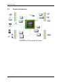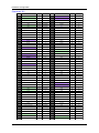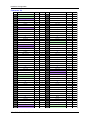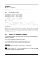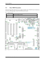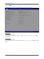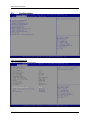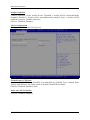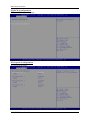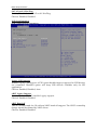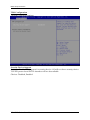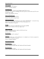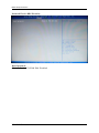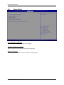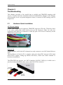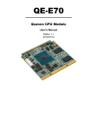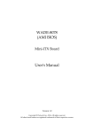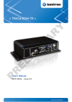
1
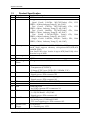
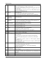
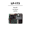
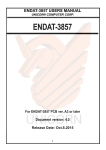
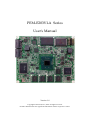
PEM-E203VLA Series User's Manual Version 1.0 Copyright © Portwell, Inc., 2014. All rights reserved. All other brand names are registered trademarks of their respective owners. Preface Table of Contents How to Use This Manual Chapter 1 System Overview ....................................................................................................... 1-1 1.1 Introduction ....................................................................................................... 1-1 1.2 Check List ........................................................................................................... 1-1 1.3 Product Specification ........................................................................................ 1-2 1.4 Mechanical Drawing......................................................................................... 1-5 1.5 System Architecture.......................................................................................... 1-6 Chapter 2 Hardware Configuration............................................................................................ 2-1 2.1 Pin definition ..................................................................................................... 2-1 Chapter 3 System Installation .................................................................................................... 3-1 3.1 Intel® Vallyview CPU ...................................................................................... 3-1 3.2 Main Memory .................................................................................................... 3-1 3.3 Installing the Single Board Computer ........................................................... 3-1 3.3.1 Chipset Component Driver .................................................................... 3-2 3.3.2 Intel® Gen7 Graphic Controller............................................................. 3-2 3.3.3 Realtek RTL811F-CG Fast Ethernet ....................................................... 3-2 3.3.4 Intel HD Audio Controller ..................................................................... 3-2 3.3.5 Intel Sideband Fabric Device .................................................................. 3-2 3.3.6 Intel Trusted Execution Engine .............................................................. 3-2 3.4 Clear CMOS Operation .................................................................................... 3-3 Chapter 4 BIOS Setup Information ............................................................................................ 4-1 4.1 Entering Setup -- Launch System Setup ........................................................ 4-1 4.2 Main .................................................................................................................... 4-2 4.3 Configuration .................................................................................................... 4-3 4.4 Security ............................................................................................................. 4-16 4.5 Boot ................................................................................................................... 4-17 4.6 Save & Exit ....................................................................................................... 4-20 Chapter 5 Troubleshooting ........................................................................................................ 5-1 5.1 Hardware Quick Installation........................................................................... 5-1 5.2 BIOS Setting ....................................................................................................... 5-2 5.3 FAQ ..................................................................................................................... 5-2 Appendix A Preface How to Use This Manual The manual describes how to configure your PEM-E203 series to meet various operating requirements. It is divided into five chapters, with each chapter addressing a basic concept and operation of this QSEVEN Module. Chapter 1 : System Overview. Presents what you have in the box and give you an overview of the product specifications and basic system architecture for this model of single board computer. Chapter 2 : Hardware Configuration. Describes the definition and location for Jumpers that you can easily configure your system. Chapter 3 : System Installation. Describes the CPU, main memory SKU to get a clear information. Chapter 4 : BIOS Setup Information. Specifies the meaning of each setup parameters, how to get advanced BIOS performance and update new BIOS. In addition, POST checkpoint list will give users some guidelines of trouble-shooting. The content of this manual and EC declaration document is subject to change without prior notice. These changes will be incorporated in new editions of the document. Portwell may make supplement or change in the products described in this document at any time. Updates to this manual, technical clarification, and answers to frequently asked questions will be shown on the following web site : http://www.portwell.com.tw System Overview Chapter 1 System Overview 1.1 Introduction Please read this manual carefully before you start with the installation of this hardware device. Also make sure that you adhere to the following rules at any time: You must discharge your body from electric power as well. Tool you use must be discharge from electric power as well. Please do not touch any device or components on the boards. Portwell, a world leading innovator in the industrial PC(IPC) market, has launched its new PEM-E203 in response to market demand for a simplified embedded system board (ESB) with longevity support. ETX® holds by ETX® industrial group defines new industrial computer platform in “Module Board” and “Carrier Board” architecture. The “Module Board” equipped processor, chipset, memory and single Ethernet controller on it. The On-The=Shelf Module board allows users to create their own Carrier Board easily and quickly since most critical parts are ready on Module board. ETX® Module board offers expansion interfaces such as PCI Express, IDE, LPT, LAN, SATA, LVDS, USB, COM and Audio ext. that could support variety function depending on Carrier board design. PEM-E203 is a addition to Portwell comprehensive ETX® form factor family; low power consumption via Intel’s Atom E38xx processor (less than 5W for a fan-less solution); DDR3L ECC memory up to 8GB; PCIe lanes; 6x USB2.0; a tested operating temperature of -40C to 85C to provide fast operating speed and maintain the small footprint. The Carrier board was customizes design to fit different mechanicalrequirements. In the meanwhile, its verity functions were also customized to meet the application. Compares to the platform that designed from nothing ETX® architecture platform only needs to develop Carrier board. Users could keep their know-how which to their core competence in the Carrier Board. 1.2 Check List The PEM-E203 series package should cover the following basic items One PEM-E203 module board If any of these items is damaged or missing, please contact your vendor and keep all packing materials for future replacement and maintenance. PEM-E203 Series User Manual 1-1 System Overview 1.3 # 1 2 Product Specification Requirement Form Factor CPU 3 Memory 4 5 6 I/O Chip BIOS Watchdog Timer 7 H/W Monitor 8 ISA 9 PCI 10 11 12 TPM I2C USB 13 PS/2 14 Serial Port 15 Parallel Port Floppy Detailed Description ․ETX ․Support Intel Vallyview DDR3LI-Series Processor – Quad Core@ 1.91GHz, 542/792(Turbo) GFx, DDR3L,~10Watt,IndustryTemp(Tj: -40~110C) – Duo Core@ 1.75GHz, 542/792(Turbo) GFx, DDR3L,~8Watt, Industry Temp (Tj: -40~110C) – Duo Core@ 1.46GHz, 533/667(Turbo) GFx, DDR3L,~7Watt, Industry Temp(Tj: -40~110C) – Duo Core@ 1.33GHz,533(No Turbo) GFx, DDR3L,~6Watt, Industry Temp(Tj: -40~110C) – Single Core@ 1.46GHz, 400(No Turbo) GFx, DDR3L,~5Watt, Industry Temp (Tj: -40~110C) 1333 1333 1066 1066 1066 ․ Support DDR3L1066/1333 ECC/Non-ECCmemory on board .shall support memory sizeoptionsof1GB,2GB,4GB and 8GB (TBD) Note: Intel Vally view I-series is up to 4GB/Intel Vally view M-series is up to 8GB ․iTEIT8721F ․TBD ․Programmable via EC F/W from 1sec. to 255min. ․iTE 8528 Embedded Controller -Temperature (CPUPECI) -Voltage (CPU Vcore, 5VSB, 12V, VDIMM, 3.3V) ․FintekF85226 LPCto ISA Bridge -Signal goes to ETX connector X2 ․iTE IT8892PCI bus mastering support -Signal goes to ETX connector X1 ․Winbond®WPCT200, TPM1.2(TBD) ․iTE 8528 Embedded Controller I2C interface ․Intel BayTrail -4x USB 2.0 portsto ETX connector X1 ․iTEIT8721F -1 x PS/2 KBand 1 x PS/2 MS -Signal goes to ETX connector X3 ․iTEIT8721F -2x Serial ports, COM1and COM2. -TTL level signals go to ETX connector X3. ․iTEIT8721F -1 x Parallel port, LPT1. PEM-E203 Series User Manual 1-2 System Overview 16 SATA 17 18 IDE Graphics Controller 19 Display Interface 20 HDACodec 21 HDACodec 22 LAN 23 24 25 Dimension PCB Power Type 26 Environment 27 28 EMI Certification Battery 29 30 BIOS SATA -1 x Floppy I/F -TTL level signals go to ETX connector X3. -Parallel port and print port are go to X3 together and share the same pins. -H/W strapping with X3, Pin 51 for FDD/PRN function definition in BIOS at boot up. ․Intel BayTrail -1x SATA Port on ETX SATA connector area. -1x On board SATA SSD ( optional to SATA connector) ․1x InnoDiskIDM368 PCI-E to PATA. ․Intel BayTrail ․1 x VGA 1 output on ETX connector X3 ․1x dual channel 24bit LVDSoutputon ETX connector X3 (LVDSis from CH7511BeDP to LVDS) ․Intel High Definition Audio interface ․Realtek ALC886 codec. ․Intel High Definition Audio interface ․Realtek ALC886 codec. ․1x Realtek®RTL811F-CGFastEthernet. -Signals go to ETX connector X4 -Wake-on-LAN and remote wake-up support ․114mm (L) x 95(W) mm x 1.6mm ․8PCB Layers, 1.6mm thick ․Power source is from ETX baseboard connector X1, X2, X3 and X4. ․External power source type is defined on baseboard. ․The ETX board shall power on with AT or ATX mode: Note: AT mode:VCC power source to ETX board without PWRBTN# event. ATX mode: VCC and 5V_SB power source to ETX board with PWRBTN# event. ․Storage Temperature: -40~ 85℃ ․Operating temperature: -40~ 85℃ ․Operation Humidity: 5% ~ 95%,non-condensing ․RoHS compliant ․CE ․FCC ClassA ․Battery 3V source is from ETX X4 ․ Battery should be implemented on baseboard if required. ․SPI Flash on board. ․90°SATA Connector *2 PEM-E203 Series User Manual 1-3 System Overview 31 32 ETX Interface ․X1 : PCI, USB, Audio ․X2 : ISA ․X3:VGA 1, LCD, COM1/2, LPT, IrDA, Mouse, Keyboard. ․X4 : IDE 1, Ethernet, Misc. Working ․When choosing component, please looking for the parts under Low withIndustrial Grade part. temp Design Notice: For the electrical components, beside the core logic, ex: CPU, MCH, ICH, Audio, LAN, etc…Please choose parts with Industrial temp support. We are going to have industrial grade temp type model on this product. PEM-E203 Series User Manual 1-4 System Overview 1.4 Mechanical Drawing PEM-E203 Series User Manual 1-5 System Overview 1.5 System Architecture PEM-E203 Series System Block Diagram PEM-E203 Series User Manual 1-6 Hardware Configuration Chapter 2 Hardware Configuration This chapter indicates connectors’ Pin Assignment. SW1 J1 J5 J6 2.1 Pin definition PEM-E203 Series User Manual 2-1 Hardware Configuration Connector X 1 X1 - Pin Pin Definition of PEM-E203 Interface I/O Type X1 - Pin Pin Definition of PEM-E203 Interface I/O Type 1 GND PWR/GND PWR/GND 51 VCC PWR/GND PWR/GND 2 GND PWR/GND PWR/GND 52 VCC PWR/GND PWR/GND 3 PCICLK3 PCI O 53 PAR PCI IO 4 PCICLK4 PCI O 54 SERR# PCI IO/OD 5 GND PWR/GND PWR/GND 55 GPERR# PCI IO 6 GND PWR/GND PWR/GND 56 NC NC NC 7 PCICLK1 PCI O 57 PEM# PCI IO/OD 8 PCICLK2 PCI O 58 USB2- USB IO 9 REQ3# PCI I 59 LOCK# PCI IO 10 GNT3# PCI O 60 DEVSEL# PCI IO 11 GNT2# PCI O 61 TRDY# PCI IO 12 Reserved 3V (Default NC) * *PWR Output 62 USB3- USB IO 13 REQ2# PCI I 63 IRDY# PCI IO 14 GNT1# PCI O 64 STOP# PCI IO 15 REQ1# PCI I 65 FRAME# PCI IO 16 Reserved 3V (Default NC) * *PWR Output 66 USB2+ USB IO 17 GNT0# PCI O 67 GND PWR/GND PWR/GND 18 NC NC NC 68 GND PWR/GND PWR/GND 19 VCC PWR/GND PWR/GND 69 AD16 PCI IO 20 VCC PWR/GND PWR/GND 70 CBE2# PCI IO 21 SERIRQ PCI IO 71 AD17 PCI IO 22 REQ0# PCI I 72 USB3+ USB IO 23 AD0 PCI IO 73 AD19 PCI IO 24 Reserved 3V (Default NC) * *PWR Output 74 AD18 PCI IO 25 AD1 PCI IO 75 AD20 PCI IO 26 AD2 PCI IO 76 USB0- USB IO 27 AD4 PCI IO 77 AD22 PCI IO 28 AD3 PCI IO 78 AD21 PCI IO 29 AD6 PCI IO 79 AD23 PCI IO 30 AD5 PCI IO 80 USB1- USB IO 31 CBE0# PCI IO 81 AD24 PCI IO 32 AD7 PCI IO 82 CBE3# PCI IO 33 AD8 PCI IO 83 VCC PWR/GND PWR/GND 34 AD9 PCI IO 84 VCC PWR/GND PWR/GND 35 GND PWR/GND PWR/GND 85 AD25 PCI IO 36 GND PWR/GND PWR/GND 86 AD26 PCI IO 37 AD10 PCI IO 87 AD28 PCI IO 38 LINE_IN_L Audio I 88 USB0+ USB IO 39 AD11 PCI IO 89 AD27 PCI IO 40 MIC Audio I 90 AD29 PCI IO 41 AD12 PCI IO 91 AD30 PCI IO 42 LINE_IN_R Audio I 92 USB1+ USB IO 43 AD13 PCI IO 93 PCIRST# PCI O 44 ASVCC (Default NC) PWR/GND PWR/GND 94 AD31 PCI IO 45 AD14 PCI IO 95 INTC# PCI IO/OD 46 LINE_OUT_L Audio O 96 INTD# PCI IO/OD 47 AD15 PCI IO 97 INTA# PCI IO/OD 48 ASGND PWR/GND PWR/GND 98 INTB# PCI IO/OD 49 CBE1# PCI IO 99 GND PWR/GND PWR/GND 50 LINE_OUT_R Audio O 100 GND PWR/GND PWR/GND PEM-E203 Series User Manual 2-2 Hardware Configuration Connector X2 X2 - Pin Pin Definition of PEM-E203 Interface I/O Type X2 - Pin Pin Definition of PEM-E203 Interface I/O Type 1 GND PWR/GND PWR/GND 51 VCC PWR/GND PWR/GND 2 GND PWR/GND PWR/GND 52 VCC PWR/GND PWR/GND 3 SD14 ISA IO 53 SA6 ISA IO 4 SD15 ISA IO 54 IRQ5 ISA I 5 SD13 ISA IO 55 SA7 ISA IO 6 MASTER# ISA I 56 IRQ6 ISA I 7 SD12 ISA IO 57 SA8 ISA IO 8 DREQ7 ISA I 58 IRQ7 ISA I 9 SD11 ISA IO 59 SA9 ISA IO 10 DACK7#/RTC_EN ISA O 60 SYSCLK ISA O 11 SD10 ISA IO 61 SA10 ISA IO 12 DREQ6 ISA I 62 REFSH# ISA IO 13 SD9 ISA IO 63 SA11 ISA IO 14 DACK6#/4E_EN ISA O 64 DREQ1 ISA I 15 SD8 ISA IO 65 SA12 ISA IO 16 DREQ5 ISA I 66 DACK1# ISA O 17 MEMW# ISA IO 67 GND PWR/GND PWR/GND 18 DACK5# ISA O 68 GND PWR/GND PWR/GND 19 MEMR# ISA O 69 SA13 ISA IO 20 DREQ0 ISA I 70 DREQ3 ISA I 21 LA17 ISA IO 71 SA14 ISA IO 22 DACK0# ISA O 72 DACK3# ISA O 23 LA18 ISA IO 73 SA15 ISA IO 24 IRQ14 ISA I 74 IOR# ISA IO 25 LA19 ISA IO 75 SA16 ISA IO 26 IRQ15 ISA I 76 IOW# ISA IO 27 LA20 ISA IO 77 SA18 ISA IO 28 IRQ12 ISA I 78 SA17 ISA IO 29 LA21 ISA IO 79 SA19 ISA IO 30 IRQ11 ISA I 80 SMEMR# ISA O 31 LA22 ISA IO 81 IOCHRDY ISA IO 32 IRQ10 ISA I 82 AEN ISA O 33 LA23 ISA IO 83 VCC PWR/GND PWR/GND 34 IO16# ISA I 84 VCC PWR/GND PWR/GND 35 GND PWR/GND PWR/GND 85 SD0 ISA IO 36 GND PWR/GND PWR/GND 86 SMEMW# ISA IO 37 SBHE# ISA IO 87 SD2 ISA IO 38 M16# ISA IO 88 SD1 ISA IO 39 SA0 ISA IO 89 SD3 ISA IO 40 OSC (CLK_14M_ISA) ISA O 90 NOWS# ISA I 41 SA1 ISA IO 91 DREQ2 ISA I 42 BALE ISA O 92 SD4 ISA IO 43 SA2 ISA IO 93 SD5 ISA IO 44 TC ISA O 94 IRQ9 ISA I 45 SA3 ISA IO 95 SD6 ISA IO 46 DACK2# ISA O 96 SD7 ISA IO 47 SA4 ISA IO 97 IOCHK# ISA I 48 IRQ3 ISA I 98 RSTDRV ISA O 49 SA5 ISA IO 99 GND PWR/GND PWR/GND 50 IRQ4 ISA I 100 GND PWR/GND PWR/GND PEM-E203 Series User Manual 2-3 Hardware Configuration Connector X3 VGA, LCD, Video, COM1, COM2, LPT/Floppy, IrDA, Mouse, Keyboard Flat-panel Interfaces EXT modules may implement an LVDS flat-panel interface or parallel, digital flat-panel interface. Please refer the board annual and specific design guide for details of this option. Pin functions for the shaded pins differ between the two flat-panel interfaces. The unshaded pins have identical functions regardless of interface type. PEM-E203 Series User Manual 2-4 Hardware Configuration X3 - Pin Pin Definition of PEM-E203 Interface I/O Type X3 - Pin Pin Definition of PEM-E203 Interface 1 GND PWR/GND PWR/GND 51 Test Point LPT I/O Type I 2 GND PWR/GND PWR/GND 52 Test Point NC NC 3 R VGA O 53 VCC PWR/GND PWR/GND 4 B VGA O 54 GND PWR/GND PWR/GND 5 HSY VGA O 55 STB# LPT OD 6 G VGA O 56 AFD# LPT OD 7 VSY VGA O 57 NC NC NC 8 V_DDC_CLK VGA IO 58 PD7 LPT OD 9 Test Point LCD O 59 IRRX IrDA I 10 V_DDC_DAT VGA IO 60 ERR# LPT OD 11 CHB_CLKN LVDS O 61 IRTX IrDA O 12 CHB_TXN3 LVDS O 62 PD6 LPT OD 13 CHB_CLKP LVDS O 63 RXD2 COM I 14 CHB_TXP3 LVDS O 64 INIT# LPT OD 15 GND PWR/GND PWR/GND 65 GND PWR/GND PWR/GND 16 GND PWR/GND PWR/GND 66 GND PWR/GND PWR/GND 17 CHB_TXP1 LVDS O 67 RTS# COM O 18 CHB_TXP2 LVDS O 68 PD5 LPT OD 19 CHB_TXN1 LVDS O 69 DTR2# COM O 20 CHB_TXN2 LVDS O 70 SLIN# LPT OD 21 GND PWR/GND PWR/GND 71 DCD2# COM I 22 GND PWR/GND PWR/GND 72 PD4 LPT OD 23 CHA_TXN3 LVDS O 73 DSR2# COM I 24 CHB_TXP0 LVDS O 74 PD3 LPT OD 25 CHA_TXP3 LVDS O 75 CTS2# COM I 26 CHB_TXN0 LVDS O 76 PD2 LPT OD 27 GND PWR/GND PWR/GND 77 TXD2 COM O 28 GND PWR/GND PWR/GND 78 PD1 LPT OD 29 CHA_TXN2 LVDS O 79 RI2# COM I 30 CHA_CLKP LVDS O 80 PD0 LPT OD 31 CHA_TXP2 LVDS O 81 VCC PWR/GND PWR/GND 32 CHA_CLKN LVDS O 82 VCC PWR/GND PWR/GND 33 GND PWR/GND PWR/GND 83 RXD1 COM I 34 GND PWR/GND PWR/GND 84 ACK# LPT OD 35 CHA_TXP0 LVDS O 85 RTS1# COM O 36 CHA_TXP1 LVDS O 86 BUSY LPT OD 37 CHA_TXN0 LVDS O 87 DTR1# COM O 38 CHA_TXN1 LVDS O 88 PE LPT OD 39 VCC PWR/GND PWR/GND 89 DCD1# COM I 40 VCC PWR/GND PWR/GND 90 SLCT# LPT OD 41 LVDS_DDC_DAT LVDS O 91 DSR1# COM I 42 Test Point LVDS O 92 MSCLK MS I/OD 43 LVDS_DDC_CLK LVDS O 93 CTS1# COM I 44 BACKLIGHT_EN LVDS O 94 MSDAT MS I/OD 45 Test Point LCD O 95 TXD1 COM O 46 VDDEN LCD O 96 KBCLK KB I/OD 47 Test Point TV O 97 RI1# COM I 48 Test Point TV O 98 KBDAT KB I/OD 49 Test Point TV O 99 GND PWR/GND PWR/GND 50 Test Point TV O 100 GND PWR/GND PWR/GND PEM-E203 Series User Manual 2-5 Hardware Configuration Connector X4 X4 - Pin Pin Definition of PEM-E203 Interface I/O Type X4 - Pin Pin Definition of PEM-E203 Interface I/O Type 1 GND PWR/GND PWR/GND 2 GND PWR/GND PWR/GND 51 NC IDE O 52 PIDE_IOR# IDE 3 5V_SB PWR/GND O PWR/GND 53 NC IDE I 4 CB_PWROK 5 PS_ON# MSIC I 54 PIDE_IOW# IDE O MSIC O 55 NC IDE IO 6 7 SPEAKER MSIC O 56 PIDE_DRQ IDE I PWRBTN# MSIC I 57 NC IDE IO 8 9 BATT PWR/GND PWR/GND 58 PIDE_D15 IDE IO KBRST# KB O 59 NC IDE 10 IO LILED# LAN O 60 PIDE_D0 IDE IO 11 Reserved RSMRST# (Default SYS_RESET#) MSIC I 61 NC IDE IO 12 ACTLED# LAN O 62 PIDE_D14 IDE IO 13 NC MSIC I 63 NC IDE IO 14 SPEEDLED# LAN O 64 PIDE_D1 IDE IO 15 NC MSIC O 65 GND PWR/GND PWR/GND 16 I2CLK (from EC) MSIC O 66 GND PWR/GND PWR/GND 17 VCC PWR/GND PWR/GND 67 NC IDE IO 18 VCC PWR/GND PWR/GND 68 PIDE_D13 IDE IO 19 USB_OC# USB I 69 NC IDE IO 20 NC MSIC I 70 PIDE_D2 IDE IO 21 EXTSMI# MSIC I 71 NC IDE IO 22 I2DAT (from EC) MSIC IO 72 PIDE_D12 IDE IO 23 SMBCLK MSIC O 73 NC IDE IO 24 SMBDATA MSIC IO 74 PIDE_D3 IDE IO 25 NC IDE O 75 NC IDE IO 26 SMBALRT# MSIC I 76 PIDE_D11 IDE IO 27 NC IDE O 77 NC IDE IO 28 DASP_S IDE O 78 PIDE_D4 IDE IO 29 NC IDE O 79 NC IDE IO 30 PIDE_CS3# IDE O 80 PIDE_D10 IDE IO 31 NC IDE O 81 VCC PWR/GND PWR/GND 32 PIDE_CS1# IDE O 82 VCC PWR/GND PWR/GND 33 GND PWR/GND PWR/GND 83 NC IDE IO 34 GND PWR/GND PWR/GND 84 PIDE_D5 IDE IO 35 NC IDE O 85 NC IDE IO 36 PIDE_A2 IDE O 86 PIDE_D9 IDE IO 37 NC IDE O 87 NC IDE IO 38 PIDE_A0 IDE O 88 PIDE_D6 IDE IO 39 NC IDE I 89 NC MSIC I 40 PIDE_A1 IDE O 90 CBLID_P IDE I 41 BATLOW# MSIC O 91 MDIN1 LAN I 42 NC MSIC O 92 PIDE_D8 IDE IO 43 NC IDE O 93 MDIP1 LAN I 44 PIDE_INTRQ IDE I 94 SIDE_D7 IDE IO 45 NC IDE I 95 MDIN0 LAN O 46 PIDE_AK# IDE O 96 PIDE_D7 IDE IO 47 NC IDE O 97 MDIP0 LAN O 48 PIDE_RDY IDE I 98 PLTRST_BUF_CR_SIO IDE O 49 VCC PWR/GND PWR/GND 99 GND PWR/GND PWR/GND 50 VCC PWR/GND PWR/GND 100 GND PWR/GND PWR/GND PEM-E203 Series User Manual 2-6 System Installation Chapter 3 System Installation This chapter provides you with instructions to set up your system. 3.1 Intel® Vallyview CPU Intel® E3845 (4 core, 10W, 1.91GHz, 1333MT) Intel® E3827 (2 core, 8W, 1.75GHz, 1333MT) Intel® E3826 (2 core, 7W, 1.46GHz, 1067MT) Intel® E3825 (2 core, 6W, 1.33GHz, 1067MT) Intel® E3815 (1 core, 5W, 1.46GHz, 1067MT) 3.2 Main Memory PEM-E203 provides DDR3L-SDRAM (1.35V) which supports 1333 MT/s as main memory, with Non-ECC/ECC(Optional) memory on board . The maximum memory can be up to 4GB . Memory clock and related settings can be detected by BIOS via SPD interface. Watch out the contact and lock integrity of memory module with socket, it will impact on the system reliability. Follow normal procedures to install memory module into memory socket. Before locking, make sure that all modules have been fully inserted into the card slots. 3.3 Installing the Single Board Computer To install your PEM-E203 into standard chassis or proprietary environment, please perform the following: Step 1 : Check all jumpers setting on proper position Step 2 : Place PEM-E203 into the dedicated position in the system Step 3 : Attach cables to existing peripheral devices and secure it WARNING Please ensure that SBC is properly inserted and fixed by mechanism. Note: Please refer to section 3.3.1 to 3.3.6 to install INF/VGA/LAN/Audio/Sideband Fabric Device/Trusted Execution Engine drivers. PEM-E203 Series User Manual 3-1 System Installation 3.3.1 Chipset Component Driver PEM-E203 uses state-of-art Intel® BayTrail-I chipset. It’s a new chipset that some old operating systems might not be able to recognize. To overcome this compatibility issue, for Windows Operating Systems such as Windows 8, please install its INF before any of other Drivers are installed. You can find very easily this chipset component driver in PEM-E203 CD-title 3.3.2 Intel® Gen7 Graphic Controller PEM-E203 has integrated Intel® Gen7 Graphic which supports DX11, OpenGL3.2. It is the most advanced design to gain an outstanding graphic performance. PEM-E203 supports VGA and Dual channel 24bit LVDS(eDP to LVDS) . Drivers Support Please find the Graphic driver in the PEM-E203 CD-title. The driver supports Windows 8. 3.3.3 Realtek RTL811F-CG Fast Ethernet PEM-E203 itself is a Module Card, the Ethernet port will support one auto negotiating 10/100/1000 Base-T Ethernet interface to the Carrier. Please find Realtek RTL811F Ethernet driver in the PEM-E203 CD-title. The driver supports Windows 8. 3.3.4 Intel HD Audio Controller Please find Intel® High Definition Audio driver and Realtek ALC886 codec form PEM-E203 CD-title. The driver supports Windows 8. 3.3.5 Intel Sideband Fabric Device Please find Intel® Sideband Fabric Device driver form PEM-E203 CD-title. The driver supports Windows 8. 3.3.6 Intel Trusted Execution Engine Please find Intel® Trusted Execution Engine driver form PEM-E203 CD-title. The driver supports Windows 8. PEM-E203 Series User Manual 3-2 System Installation 3.4 Clear CMOS Operation The following table indicates how to enable/disable Clear CMOS Function hardware circuit by putting jumper of the PEM-C200 carrier board. JP4:CMOS Setting Jumper Setting Describe Default *1-2 2-3 Clean CMOS PEM-E203 Series User Manual 3-3 BIOS Setup Information Chapter 4 BIOS Setup Information PEM-E203 is equipped with the AMI BIOS stored in Flash ROM. These BIOS has a built-in Setup program that allows users to modify the basic system configuration easily. This type of information is stored in CMOS RAM so that it is retained during power-off periods. When system is turned on, PEM-E203 communicates with peripheral devices and checks its hardware resources against the configuration information stored in the CMOS memory. If any error is detected, or the CMOS parameters need to be initially defined, the diagnostic program will prompt the user to enter the SETUP program. Some errors are significant enough to abort the start up. 4.1 Entering Setup -- Launch System Setup Power on the computer and the system will start POST (Power On Self Test) process. When the message below appears on the screen, press <Del> key will enter BIOS setup screen. Press <Del> to enter SETUP If the message disappears before responding and still wish to enter Setup, please restart the system by turning it OFF and On or pressing the RESET button. It can be also restarted by pressing <Ctrl>, <Alt>, and <Delete> keys on keyboard simultaneously. Press <F1> to Run General Help or Resume The BIOS setup program provides a General Help screen. The menu can be easily called up from any menu by pressing <F1>. The Help screen lists all the possible keys to use and the selections for the highlighted item. Press <Esc> to exit the Help screen. PEM-E203 Series User Manual 4-1 BIOS Setup Information 4.2 Main Use this menu for basic system configurations, such as time, date etc. System Date View or set system date. The date format is <Day>, <Month> <Date> <Year>. Use [+] or [-] to configure system Date. System Time View or set system time. The time format is <Hour> <Minute> <Second>. Use [+] or [-] to configure system Time. PEM-E203 Series User Manual 4-2 BIOS Setup Information 4.3 Configuration CPU Configuration CPU Configuration Parameters. PEM-E203 Series User Manual 4-3 BIOS Setup Information Active Processor Cores Number of cores to enable in each processor package. Choices: All, 1. Intel Virtualization Technology When enabled, a VMM can utilize the additional hardware capabilities provided by Vanderpool Technology. Choices: Disabled, Enabled. EIST Enable/Disable Intel SpeedStep. Choices: Disabled, Enabled. CPU C6 report Enable/Disable CPU C6 (ACPI C3) report to OS. Choices: Disabled, Enabled. Chipset Configuration Configuration Chipset Feature. High Precision Timer Enable or Disable the High Precision Event Timer. Choices: Disabled, Enabled. PEM-E203 Series User Manual 4-4 BIOS Setup Information Audio Controller Control Detection of the Azalia device. Disabled = Azalia will be unconditionally disabled. Enabled = Azalia will be unconditionally enabled. Auto = Azalia will be enabled if present. Disable otherwise. Choices: Disabled, Enabled. LAN Configuration Configuration On Board LAN Device. Launch Legacy PXE Rom Launch Legacy PXE Rom. [Disable] Not launch Rom, [Enable] Force Launch Rom, [Auto] Auto detect LAN Cable status to Enable/Disable Rom initial. Choices: Disabled, Enabled, Auto. Wake on LAN Controller Choices: Disabled, Enabled. PEM-E203 Series User Manual 4-5 BIOS Setup Information Graphics Configuration Configuration Graphics Settings. GOP Configuration GOP Driver Enable GOP Driver will unload VBIOS; Disable it will load VBIOS. Choices: Enabled, Disabled. Intel IGD Configuration Integrated Graphics Device Enable: Enable Integrated Graphics Device (IGD) when selected as the Primary Video Adapter. Disable: Always disable IGD. Choices: Enabled, Disabled. IGD Turbo Enable Enable: Enable IGD Turbo Enable. Disable: IGD Turbo Disable. Choices: Enabled, Disabled. Primary Display Select which of IGD/PCI Graphics device should be Primary Display. Choices: Auto, IGD, PCI, SG. PEM-E203 Series User Manual 4-6 BIOS Setup Information DVMT Pre-Allocated Select DVMT 5.0 Pre-Allocated (Fixed) Graphics Memory sized used by the Internal Graphic Device. Choices: 64M, 96M, 128M, 160M, 192M, 224M, 256M, 288M, 320M, 352M, 384M, 416M, 448M, 480M, 512M. DVMT Total Gfx Mem Select DVMT 5.0 Total Graphic Memory size used by the Internal Graphics Device. Choices: 128MB, 256MB, Max. IGD Output Display Control - CSM Primary IGFX Boot Display Select the video device which will be activated during POST. This has no effect if external graphics present. Secondary boot display selection will appear based on your election. VGA modes will be supported only on primary display. Choices: VBIOS Default, CRT,LFP. LCD Panel Type Select LCD panel used by Internal Graphics Device by selecting the appropriate setup item. Choices: VBIOS Default, 640x480 LVDS, 800x600 LVDS, 1024x768 LVDS, 1280x1024 LVDS, 1400x1050 (RB) LVDS, 1400x1050 LVDS, 1600x1200 LVDS, 1366x768 LVDS, 1680x1050 LVDS, 1920x1200 LVDS, 1440x900 LVDS, 1600x900 LVDS, 1280x800 LVDS, 1920x1080 LVDS, 2048x1536 LVDS. Panel Scaling Select the LCD Panel scaling option used by Internal Graphic device Choices: Auto, Off, Force Scaling. Backlight Control Back Light Control Setting Choices: PWM Inverted, PWM Normal, GMBus Inverted, GMBus Normal. Active LFP Select the Active LFP configuration. Choices: No LVDS, eDP Port-A. PEM-E203 Series User Manual 4-7 BIOS Setup Information PCI/PCIE Configuration PCI and PCI Express Settings. PCI Express Configuration PCI Express Settings. PEM-E203 Series User Manual 4-8 BIOS Setup Information PCI Express Port 0-3 Enable or Disable the PCI Express Port 0-3 in the Chipset. Choices: Enabled, Disabled. Speed Configuration PCIe Port Speed. Choices: Auto, Gen2, Gen1. SATA configuration SATA Device Option Settings. Serial-ATA (SATA) Enable/Disable Serial ATA. Choices: Enabled, Disabled. SATA Mode Select IDE/AHCI. Choices: IDE Mode, AHCI Mode. Serial-ATA Port 0-1 Enable/Disable Serial ATA Port 0-1. Choices: Enabled, Disabled. PEM-E203 Series User Manual 4-9 BIOS Setup Information SATA Port 0-1 Hot Plug Enable/Disable Serial ATA Port 0-1 HotPlug. Choices: Enabled, Disabled. USB Configuration USB Configuration Parameters. Legacy USB Support Enables Legacy USB support. AUTO option disables legacy support if no USB devices are connected. Disabled option will keep USB devices available only for EFI application. Choices: Enabled, Disabled, Auto. xHCI Legacy Support Enable/Disable XHCI Controller Legacy support. Choices: Enabled, Disabled. xHCI Hand-off This is a workaround for OS without XHCI hand-off support. The XHCI ownership change should be claimed by XHCI driver. Choices: Enabled, Disabled. PEM-E203 Series User Manual 4-10 BIOS Setup Information EHCI Hand-off This is a workaround for OS without EHCI hand-off support. The EHCI ownership change should be claimed by EHCI driver. Choices: Enabled, Disabled. USB Mass Storage Driver Support Enable/Disable USB Mass Storage Driver Support. Choices: Enabled, Disabled. USB Configuration USB Configuration Settings. USB 2.0 (EHCI) Support Control the USB EHCI (USB 2.0) function. One EHCI controller must always be enabled. Choices: Disabled, Enabled. USB RMH Mode Choices: Disabled, Enabled. USB Port 0~3 Enable/Disable USB port 0~3 Choices: Disabled, Enabled. PEM-E203 Series User Manual 4-11 BIOS Setup Information Power Control Configuration System Power Control Configuration Parameters. Enable Hibernation Enable or Disable system ability to Hibernate (OS/S4 Sleep State). This option may be not effective with some OS. Choices: Disabled, Enabled. ACPI Sleep state Select the highest ACPI sleep state the system will enter when the SUSPEND button is pressed. Choices: Suspend Disabled, S3 (Suspend to RAM). Restore AC Power Loss Select AC power state when power is re-applied after a power failure. Choices: Power off, Power On, Last State. PEM-E203 Series User Manual 4-12 BIOS Setup Information TPM Configuration Trusted Computing Settings. Security Device Support Enable or Disable BIOS support for security device. OS will not show security device. TCG EFI protocol and INT1A interface will not be available. Choices: Disabled, Enabled. PEM-E203 Series User Manual 4-13 BIOS Setup Information Super IO Configuration Super I/O configuration Serial Port 1 Choices: Disabled, Enabled. Serial Port 2 Choices: Disabled, Enabled. Parallel Port Choices: Disabled, Enabled. PEM-E203 Series User Manual 4-14 BIOS Setup Information H/W Monitor Monitor Hardware Status. Serial Port Console Redirection PEM-E203 Series User Manual 4-15 BIOS Setup Information COM 0 Console Redirection Choices: Disabled, Enabled. COM 1 Console Redirection Choices: Disabled, Enabled. 4.4 Security Administrator Password Set Administrator Password. User Password Set User Password. PEM-E203 Series User Manual 4-16 BIOS Setup Information 4.5 Boot Boot configuration Setup Prompt Timeout Number of seconds to wait for setup activation key. 65535 (0xFFFF) means indefinite waiting. Choices: 0, 1, etc. Bootup NumLock State Select the keyboard Numlock state. Choices: On, off. Post Report Post report support enable/disable. Choices: Disabled, Enabled. Summary Screen Summary Screen support Enable/Disable. Choices: Disabled Enabled. PEM-E203 Series User Manual 4-17 BIOS Setup Information CSM Support Enable/Disable CSM support. Choices: Disabled, Enabled. GateA20 Active UPON REQUEST – GA20 can be disabled using BIOS services. ALWAYS – do not allow disabling GA20; this option is useful when any RT code is excused above 1MB. Choices: Upon Request, Always. Option ROM Messages Set display mode for option ROM Choices: Force BIOS, Keep Current. INI19 Trap Response BIOS reaction on INT19 trapping by option ROM: IMMEDIATE – execute the trap right away; POSTPONED – execute the trap during legacy boot. Choices: Immediate, Postponed. Storage Controls the execution of UEFI and Legacy Storage OpROM. Choices: Do not launch, UEFI only, Legacy only. Full Screen Logo Enable or Disable quiet boot option and full screen logo. Choices: Disabled, Enabled. OS Selection Choices: Windows 8.X, windows 7. Fast Boot Enable or disable boot with initialization of a minimal set of devices required to launch active for BBS boot options. Choices: Disabled, Enabled. Boot Option Priorities Boot Option #1 Sets the system boot order. Choices: Realtek PXE B04 D00, UEFI: Built-in EFI Shell, Disabled. Boot Option #2 Sets the system boot order. Choices: Realtek PXE B04 D00, UEFI: Built-in EFI Shell, Disabled. PEM-E203 Series User Manual 4-18 BIOS Setup Information Network Device BBS Priorities Boot Option #1 Choices: Realtek PXE B04 D00, Disabled. PEM-E203 Series User Manual 4-19 BIOS Setup Information 4.6 Save & Exit Save Changes and Reset Reset the system after saving the changes. Disable Changes and Reset Reset system setup without saving any changes. Restore Defaults Restore/Load Default values for all the setup options. PEM-E203 Series User Manual 4-20 Trouble shooting Chapter 5 Troubleshooting This chapter provides a few useful tips to quickly get PEM-E203 running with success. As basic hardware installation has been addressed in Chapter 2, this chapter will primarily focus on system integration issues, in terms of BIOS setting, and OS diagnostics. 5.1 Hardware Quick Installation ATX Power Setting Unlike other Single board computer, PEM-E203 supports ATX only. Therefore, there is no other setting that really needs to be set up. However, there are only two connectors that must be connected—CN18 (20 pins ATX Power Connector) in the PEM-C200 carrier board. Serial ATA Unlike IDE bus, each Serial ATA channel can only connect to one SATA hard disk at a time; The installation of Serial ATA is simpler and easier than IDE, because SATA hard disk doesn’t require setting up Master and Slave, which can reduce mistake of hardware installation. The PEM-E203 can support two SATA interface (SATAII, 3.0Gb/s) of which one is used for Onboard SSD,the other one to the ETX SATA connector. PEM-E203 Series User Manual 5-1 Trouble shooting PATA The PEM-E203 can support two PATA ports(CN16 & CN17) on PEM-C200 carrier board. 5.2 BIOS Setting It is assumed that users have correctly adopted modules and connected all the devices cables required before turning on ATX power. USB keyboard and mouse, SATA hard disk, VGA connector, power cable of the devices, ATX accessories are good examples that deserve attention. With no assurance of properly and correctly accommodating these modules and devices, it is very possible to encounter system failures that result in malfunction of any device. To make sure that you have a successful start with PEM-E203, it is recommended, when going with the boot-up sequence, to hit “F2” key and enter the BIOS setup menu to tune up a stable BIOS configuration so that you can wake up your system far well. Loading the default optimal setting When prompted with the main setup menu, please scroll down to “Load Setup Defaults”, press “Enter” and select “Yes” to load in default optimal BIOS setup. This will force your BIOS setting back to the initial factory configuration. It is recommended to do this so you can be sure the system is running with the BIOS setting that Portwell has highly endorsed. As a matter of fact, users can load the default BIOS setting any time when system appears to be unstable in boot up sequence. 5.3 FAQ Information & Support Question: I forget my password of system BIOS, what am I supposed to do? Answer: You can switch off your power supply then find the JP4 of the PEM-C200 carrier board to set it from 1-2 short to 2-3 short and wait 5 seconds to clean your password then set it back to 1-2 short to switch on your power supply. JP4:CMOS Setting Jumper Setting Describe *1-2 Default 2-3 Clean CMOS PEM-E203 Series User Manual 5-2 Trouble shooting Question: How to update the BIOS file of the PEM-E203? Answer: 1. Please visit web site of the Portwell download center as below hyperlink http://www.portwell.com.tw/support/download_center.php But you must register an account first. (The E-Mail box should be an existing Company email address that you check regularly.) http://www.portwell.com.tw/member/newmember.php 2. Input your User name and password to log in the download center. 3. Select the “Search download” to input the keyword “PEM-E203”. 4. Find the “BIOS “page to download the ROM file and flash utility. 5. Execute the zip file to root of the bootable USB pen drive. You can get hose“fparts.txt”,”fpt64.efi”,”temp.bin”,”Update.nsh” four files. 6. Insert your USB pen drive in USB port of the PEM-C200 carrier board .and power-on. PEM-E203 Series User Manual 5-3 Trouble shooting 7. Boot to EFI-Shell mode then input the “fs0:” command to switch to the .root of the USB pen drive. 8. Type ”update” command to start flash BIOS processes. 9. When it finished all BIOS writing processes back to “fs0:\>”, please cut the AC power off and wait 10 seconds then power on. PEM-E203 Series User Manual 5-4 Trouble shooting 10. Please press the “F2” key to BIOS setup menu to select “Load Setup efaults” and then select “Exit Saving Changes” option to finish all BIOS flash processes. Note: Please visit our Download Center to get the Catalog, User manual, BIOS, and driver files. http://www.portwell.com.tw/support/download_center.php If you have other additional technical information or request which is not covered in this manual, please fill in the technical request form as below hyperlink. http://www.portwell.com.tw/support/problem_report.php We will do our best to provide a suggestion or solution for you. Thank PEM-E203 Series User Manual 5-5