1
WADE-8078
(AMI BIOS)
Mini-ITX Board
User's Manual
Version 1.0
Copyright © Portwell, Inc., 2014. All rights reserved.
All other brand names are registered trademarks of their respective owners.
Preface
Table of Contents
How to Use This Manual
Chapter 1 System Overview.......................................................................................................1-1
1.1 Introduction ....................................................................................................... 1-1
1.2 Check List........................................................................................................... 1-1
1.3 Product Specification........................................................................................ 1-2
1.3.1 Mechanical Drawing................................................................................ 1-4
1.4 System Architecture.......................................................................................... 1-6
Chapter 2 Hardware Configuration ...........................................................................................2-1
2.1 Jumper Setting ................................................................................................... 2-1
2.2 Connector Allocation........................................................................................ 2-9
Chapter 3 System Installation....................................................................................................3-1
3.1 Intel® Valleyview CPU .................................................................................... 3-1
3.2 Main Memory .................................................................................................... 3-1
3.3 Installing the Single Board Computer............................................................ 3-1
3.3.1 Chipset Component Driver .................................................................... 3-2
3.3.2 Intel® HD Graphics 4600 ........................................................................ 3-2
3.3.3 Intel LAN I210IT / I210IAT co-lay Gigabit Ethernet Controller....... 3-2
3.3.4 Realtek ALC892 HD Audio Controller ................................................. 3-2
3.4 Clear CMOS Operation .................................................................................... 3-2
3.5 WDT Function ................................................................................................... 3-3
3.6 GPIO.................................................................................................................... 3-5
Chapter 4 BIOS Setup Information............................................................................................4-1
4.1 Entering Setup -- Launch System Setup ........................................................ 4-1
4.2 Main .................................................................................................................... 4-2
4.3 Configuration .................................................................................................... 4-3
4.4 Security ............................................................................................................. 4-16
4.5 Boot ................................................................................................................... 4-17
4.6 Save & Exit ....................................................................................................... 4-19
Chapter 5 Troubleshooting ........................................................................................................5-1
5.1 Hardware Quick Installation........................................................................... 5-1
5.2 BIOS Setting ....................................................................................................... 5-2
5.3 Q&A .................................................................................................................... 5-2
Preface
How to Use This Manual
The manual describes how to configure your WADE-8078 system board to meet
various operating requirements. It is divided into five chapters, with each chapter
addressing a basic concept and operation of Single Host Board.
Chapter 1: System Overview. Presents what you have in the box and give you an
overview of the product specifications and basic system architecture for this series
model of single host board.
Chapter 2: Hardware Configuration. Show the definitions and locations of Jumpers
and Connectors that you can easily configure your system.
Chapter 3: System Installation. Describes how to properly mount the CPU, main
memory and Compact Flash to get a safe installation and provides a programming
guide of Watch Dog Timer function.
Chapter 4: BIOS Setup Information. Specifies the meaning of each setup
parameters, how to get advanced BIOS performance and update new BIOS. In
addition, POST checkpoint list will give users some guidelines of trouble-shooting.
Chapter 5: Troubleshooting. Provide various of useful tips to quickly get
WADE-8078 running with success. As basic hardware installation has been addressed
in Chapter 3, this chapter will basically focus on system integration issues, in terms of
backplane setup, BIOS setting, and OS diagnostics.
The content of this manual is subject to change without prior notice. These changes
will be incorporated in new editions of the document. The vendor may make
supplement or change in the products described in this document at any time.
System Overview
Chapter 1
System Overview
1.1
Introduction
Powell Inc., a world-leading innovator in the Industrial PC (IPC) market and a
member of the Intel® Communications Alliance, has launched its new
WADE-8078
series in response to market demand for a simplified embedded system board
(ESB)
that combines a smaller footprint, lower power consumption, robust computing
power and with longevity support.
Built with Intel’s latest chipset, WADE-8078 series take advantage of the Intel®
Atom™ Valleyview E38XX series processors.
WADE-8078 has lots of features, also features one SATA connectors (SATA
3Gb/s) storage specification , one DDR3 SO-DIMM memory slot for DDR3L ECC
SDRAM up to 4GB, support total 3 USB ports (1x USB3.0 on REAR I/O,2x USB2.0
on board), VGA / HDMI display ,one Gigabit Ethernet, and one PCIe x4 slot
(PCIe x2 signal) and support CFEX.
WADE-8078’s ability to drive two displays simultaneously makes them
particularly suitable for lottery and gaming applications. They are also ideal for
applications such as point-of-sale (POS), digital signage, kiosks .
1.2
Check List
The WADE-8078 package should cover the following basic items
9
9
9
9
9
One WADE-8078 Mini-ITX Main Board
One 8 Pin Power Cable
One SATA Cable
One I/O Shield bracket
One Installation Resources CD-Title
If any of these items is damaged or missing, please contact your vendor and keep
all packing materials for future replacement and maintenance.
WADE-8078 User’s Manual
1-1
System Overview
1.3
Product Specification
z Main Processor
- Intel® Atom™ Valleyview E38XX series processor
z System BIOS
AMI BIOS
z Main Memory
One 204 - pin DDR3 SODIMM socket support DDR3L up to 4GB 1066/1333
MHz ECC memory(only use ECC memory)
- E3845 / E3827 support 1333MHz memory
- E3826 / E3825 / E3815 support 1066MHz memory
z Expansion Interface
One PCIex4(PCIex2 signal)
z SATA Interface
One SATA ports(SATA 3Gb)
z Serial Port
Support one RS232 / one RS232/422/485
z USB Interface
Support three USB (Universal Serial Bus) ports, one USB3.0 on rear I/O and
two USB2.0 on board header for internal devices
z Audio Interface
Connector for Line-Out(Line in / Line out / Mic in on board 8 pin header)
z Real Time Clock/Calendar (RTC)
Support Y2K Real Time Clock/Calendar
z Watch Dog Timer
- Support WDT function through software programming for enable/disable
and interval setting
- General system reset
z On-board Ethernet LAN
One Gigabit Ethernet (10/100/1000 Mbits/sec) LAN ports
z High Drive GPIO
z One pin-header for 8 bit GPIO
z System Monitoring Feature
Monitor system temperature and major power sources.
z Outline Dimension (L x W)
170mm(6.69’’) x 170mm(6.69’’)
z Power Requirements
WADE-8078 User’s Manual
1-2
System Overview
z Configuration
CPU Type
SBC BIOS
ECC Memory
VGA Card
VGA Driver
LAN Card
LAN Driver
Audio Card
Audio Driver
Chip Driver
USB 3.0 Driver
3.5” SATA-2 HDD
CFEX
USB DVD-ROM
Power Supply
Genuine Intel® CPU@ 1.91 GHz Atom L3:2M Bytes
Portwell, Inc. WADE-8078 BIOS ( 30903T00 ) EVALUATION COPY
WARIS DDR3L SO-DIMM 1333 4GB*1 (hynix H5TC2G83EFR)
Onboard Intel(R) HD Graphics
Intel(R) HD Graphics Version:10.18.10.3266
Onboard Intel(R) I210 Gigabit Network Connection
Intel(R) I210 Gigabit Network Connection Version:12.7.28.0
Onboard Realtek High Definition Audio Controller
Realtek High Definition Audio Version:6.0.1.6873
Intel (R) Chipset Device Software Version:9.4.4.1005
Intel (R) USB 3.0 eXtensible Host Controller Version: 6.2.9200.16384
Western Digital WD5002ABYS 500GB
WARIS CFEX 4GB PWG B473D350-002
Transcend TS8XDVDRW-K
Portwell, ORION-D4601 460W
z Operating Temperature
0 °C ~ 60 °C
z Storage temperature
-20 ~ 80 °C
z Relative Humidity
0% ~ 90%, non-condensing
WADE-8078 User’s Manual
1-3
System Overview
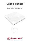
1.3.1
Mechanical Drawing
WADE-8078 User’s Manual
1-4
System Overview
WADE-8078 User’s Manual
1-5
System Overview
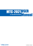
1.4
System Architecture
All of details operating relations are shown in WADE-8078 System Block
Diagram.
WADE-8078 System Block Diagram
WADE-8078 User’s Manual
1-6
Hardware Configuration
Chapter 2
Hardware Configuration
This chapter gives the definitions and shows the positions of jumpers, headers and
connectors. All of the configuration jumpers on WADE-8078 are in the proper
position. The default settings shipped from factory are marked with an asterisk (♣).
2.1
Jumper Setting
In general, jumpers on the single board computer are used to select options for certain
features. Some of the jumpers are designed to be user-configurable, allowing for
system enhancement. The others are for testing purpose only and should not be
altered. To select any option, cover the jumper cap over (SHORT) or remove (NC) it
from the jumper pins according to the following instructions. Here NC stands for
“Not Connect”.
WADE-8078 User’s Manual
2-1
Hardware Configuration
WADE-8078 User’s Manual
2-2
Hardware Configuration
The jumper settings are schematically depicted in this manual as follows:
JP1: Watch Dog Timer Enable
PIN No
1-2 open
1-2 short
Signal Function
Disable Ì
Enable
JP2: GPO Voltage Select
PIN No
1-2 short
2-3 short
Signal Function
+5V Ì
+3.3V
WADE-8078 User’s Manual
2-3
Hardware Configuration
JP5: BIOS Select
PIN No
1-2 short
2-3 short
Signal Function
SPI Flash Ì
CFEX BIOS
JP6: Clear CMOS
PIN No
1-2 short
2-3 short
Signal Function Function
Normal Ì
Clear CMOS
J1: GPIO
Pin No.
1
3
5
7
9
Signal Description
LPC_GPIO0 (GPJ0)
LPC_GPIO1 (GPJ1)
LPC_GPIO2 (GPJ2)
LPC_GPIO3 (GPJ3)
GND
Pin No.
2
4
6
8
10
Signal Description
EC_GPO4 (GPE0)
EC_GPO5 (GPE7)
EC_GPO6 (GPC0)
EC_GPO7 (GPG0)
+5V
Pin No.
2
4
6
8
10
Signal Description
Keyboard Date
J2: Keyboard & Mouse Pin HDR
Pin No.
1
3
5
7
9
Signal Description
Mouse Data
Key( no pin )
Ground
+5V_Dual
Mouse Clock
WADE-8078 User’s Manual
Key( no pin )
Ground
+5V_Dual
Keyboard Clock
2-4
Hardware Configuration
J3:Front Panel System Connector
Pin No.
1
3
5
7
9
11
13
15
Signal Description
PWR_LED(+)
PWR_LED(-)
J17 LAN_ACT(+)
J17 LAN_LINK(-)
N/C
N/C
HDD_LED(+)
HDD_LED(-)
Pin No.
2
4
6
8
10
12
14
16
Signal Description
Speaker(+)
N/C
N/C
Speaker(-)
GND
Power Button
Rest
GND
Pin No.
2
4
6
8
10
12
14
Signal Description
Ground
N/C
+5V
LAD2
LAD1
Ground
SMB_DATA
J4: TPM Connector
Pin No.
1
3
5
7
9
11
13
Signal Description
TPM Clock
LFRAME#
PLTRST#
LAD3
+3.3V
LAD0
SMB_CLK
J6: System FAN Connector
PIN No
1
2
3
Signal Function
GND
+12V
SENSE
WADE-8078 User’s Manual
2-5
Hardware Configuration
J9: SATA Power
PIN No
1
2
3
4
Signal Function
+12V
Ground
Ground
+5V
J10: External USB Connector
Pin No.
1
3
5
7
9
Signal Description
5V Dual
USBUSB+
Ground
Pin No.
2
4
6
8
10
Signal Description
5V Dual
USBUSB+
Ground
N/C
Signal Description
Data Carrier Detect
Transmit Data
GND
Request To Send
Ring Indicator
Pin No.
2
4
6
8
10
Signal Description
Receive Data
Data Terminal Ready
Data Set Ready
Clear To Send
KEY
J14: COM2
Pin No.
1
3
5
7
9
J18: Audio MIC/Line-in/Line-out Connector
WADE-8078 User’s Manual
2-6
Hardware Configuration
Pin No.
1
3
5
7
9
Signal Description
MIC with Reference Voltage
Line-in Left Channel
Line-in Right Channel
Line-out Left Channel
Line-out Right Channel
Pin No.
2
4
6
8
10
Signal Description
Analog Ground
Analog Ground
Analog Ground
Analog Ground
KEY
CN1: 8 Pin ATX Connector
PIN No
1
2
3
4
5
6
7
8
Signal Description
+5V
+5V
+5Vsb
+12V
PS_ON#
Ground
Ground
Ground
SW1: ATX Detect &BIOS Recovery Switch
No.
1
3
Signal Description
ATX Detect
BIOS Recovery
WADE-8078 User’s Manual
On
AT Mode
Enable
Off
ATX Mode
Disable
2-7
Hardware Configuration
J20: HDMI Connector
Pin No.
1
3
5
7
9
11
13
15
17
19
Signal Description
D_HDMI_D0+
D_HDMI_D0GND
D_HDMI_D2+
D_HDMI_D2GND
N/C
D_HDMI_DDC_CLK
GND
D_HDMI_HPD_IN
Pin No.
2
4
6
8
10
12
14
16
18
20
Signal Description
GND
D_HDMI_D1+
D_HDMI_D1GND
D_HDMI_D3+
D_HDMI_D3N/C
D_HDMI_DDC_DATA
VCC
J19: Audio connector
PIN No
Green
Signal Description
Line-Out
J21: COM1 Serial Port Connector
Pin No.
1
2
3
4
5
6
7
8
9
10
Signal Description
RS-232
DCD (Data Carrier Detect)
DSR (Data Set Ready)
RXD (Receive Data)
RTS (Request to Send)
TXD (Transmit Data)
CTS (Clear to Send)
DTR (Data Terminal Ready)
RI (Ring Indicator)
GND (Ground)
N/C
RS-422 (COM2)
TXN/C
TX+
N/C
RX+
N/C
RXN/C
GND
N/C
RS-485 (COM2)
DATAN/C
DATA+
N/C
N/C
N/C
N/C
N/C
GND
N/C
J22: VGA Connector
Pin No.
1
2
3
4
5
6
7
8
Signal Description
CRT_R
CRT_G
CRT_B
N/C
GND
GND
GND
GND
WADE-8078 User’s Manual
Pin No.
9
10
11
12
13
14
15
Signal Description
VCC
GND
N/C
VGA_DDCDA
CRT_HS
CRT_VS
VGA_DDCCL
2-8
Hardware Configuration
2.2
Connector Allocation
I/O peripheral devices are connected to the interface connectors.
Connector Function List
Connector
Function
J1
GPIO
J2
Keyboard & Mouse Pin HDR
J3
Front Panel System Connector
J4
TPM Connector
J6
System FAN Connector
J7
DDR3L ECC SO-DIMM Connector
J8
Mini PCI-E
J9
SATA Power
J10
J11
External USB Connector
SATA Connector
J12
PCI-E X4 Connector (Only X2 Lan)
J14
COM 2 Serial Port Connector
J16
USB 3.0 Connector
J17
LAN Connector
J18
Audio MIC/Line-in/Line-out Connector
J19
Audio Jack (Line-Out)
J20
HDMI Connector
J21
COM 1 Serial Port Connector
J22
VGA Connector
J23
CFEX Connector
JP1
JP2
JP5
JP6
SW1
U2
U4
U14
Watch Dog Timer Enable
GPO Voltage Select
BIOS Select
Clear CMOS
ATX Detect &BIOS Recovery Switch
EC EEPROM Socket
BIOS Socket
Bay Trail-I CPU
WADE-8078 User’s Manual
Remark
Only Support RS-232
Support RS-232/422/485
2-9
System Installation
Chapter 3
System Installation
This chapter provides you with instructions to set up your system. The additional
information is enclosed to help you set up onboard PCI device and handle Watch Dog
Timer (WDT) and operation of GPIO in software programming.
3.1
Intel® Valleyview CPU
Intel® Atom(TM) E3845 CPU (4 Core, 10W, 1.91GHz, 1333MT)
3.2
Main Memory
WADE-8078 provides 1 x 204-pin SO-DIMM sockets which supports DDR3L memory
(support ECC function only) as main memory, ECC (Error Checking and Correcting).
The maximum memory can be up to 4GB. Memory clock and related settings can be
detected by BIOS via SPD interface.
Watch out the contact and lock integrity of memory module with socket, it will
impact on the system reliability. Follow normal procedures to install memory module
into memory socket. Before locking, make sure that all modules have been fully
inserted into the card slots.
3.3
Installing the Single Board Computer
WADE-8078 provides 1 x 204-pin SO-DIMM sockets which supports DDR3L memory
(support ECC function only) as main memory, ECC (Error Checking and Correcting).
The maximum memory can be up to 4GB. Memory clock and related settings can be
detected by BIOS via SPD interface.
Watch out the contact and lock integrity of memory module with socket, it will
impact on the system reliability. Follow normal procedures to install memory module
into memory socket. Before locking, make sure that all modules have been fully
inserted into the card slots.
WARNING
Please ensure that SBC is properly inserted and fixed by mechanism.
Note:
Please refer to section 3.3.1 to 3.3.6 to install INF/VGA/LAN/Audio/Sideband
Fabric Device/Trusted Execution Engine drivers.
WADE-8078 User’s Manual
3-1
System Installation
3.3.1
Chipset Component Driver
WADE-8078 uses state-of-art Intel® BayTrail-I chipset. It’s a new chipset that some
old operating systems might not be able to recognize. To overcome this compatibility
issue, for Windows Operating Systems such as Windows 8, please install its INF
before any of other Drivers are installed. You can find very easily this chipset
component driver in WADE-8078 CD-title
3.3.2
Intel® HD Graphics 4600
WADE-8078 has integrated Intel® HD Graphics 4600 which supports DX11,
OpenGL3.2. It is the most advanced design to gain an outstanding graphic
performance. WADE-8078 supports VGA and dual display. This combination makes
WADE-8078 an excellent piece of multimedia hardware.
Drivers Support
Please find the Graphic driver in the WADE-8078 CD-title. The driver supports
Windows 8.
3.3.3
Intel LAN I210IT / I210IAT co-lay Gigabit Ethernet Controller
Drivers Support
Please find Intel LAN I210IT / I210IT co-lay LAN driver in /Ethernet directory of
WADE-8078 CD-title. The driver supports Windows 8.
3.3.4
Realtek ALC892 HD Audio Controller
Please find Realtek ALC892 HD Audio driver form WADE-8078 CD-title. The driver
supports Windows 8.
3.4
Clear CMOS Operation
The following table indicates how to enable/disable Clear CMOS Function hardware
circuit by putting jumper in the board.
JP6: CMOS Setting
JP1
*1-2
2-3
Jumper Setting Describe
Normal
Clean CMOS
WADE-8078 User’s Manual
3-2
System Installation
3.5
WDT Function
#include <stdio.h>
#include <stdlib.h>
#include <conio.h>
#include <dos.h>
#define EC_DATA 0x62
#define EC_CMD 0x66
#define EC_CMD_READ 0x80
#define EC_CMD_WRITE 0x81
#define WDT_MODE 0x06 // WDT Select mode.
#define WDT_MIN 0x07 // Minute mode counter
#define WDT_SEC 0x08 // Second mode counter
// Use port 62 and port 66 to access EC command / data.
WADE-8078 User’s Manual
3-3
System Installation
static int IBF_Check()
{
System Installation
WADE-8078 User’s Manual 3-4
unsigned char IBF_status;
do
{
pw_udelay (20); // delay 20 us
outportb (EC_CMD, &IBF_status);
} while (IBF_status & 0x02);
return 1;
}
static int OBF_Check ()
{
unsigned char OBF_status;
do
{
pw_udelay (20); // delay 20 us
OBP_status = inportb (EC_CMD);
} while (!(OBF_status & 0x01));
return 1;
}
static void Write_EC (unsigned char index, unsigned char data)
{
IBF_Check ();
outportb (EC_CMD, EC_CMD_WRITE);
IBF_Check ();
outportb (EC_DATA, index);
IBF_Check ();
outportb (EC_DATA, data);
}
static unsigned char Read_EC (unsigned char address)
{
unsigned char data;
IBF_Check ();
outportb (EC_CMD, EC_CMD_READ);
IBF_Check ();
outportb (EC_DATA, address);
OBF_Check();
data = inportb (EC_DATA);
return data;
}
void EC_WDT_Trigger ()
{
/* WDT Counter */
Write_EC (WDT_SEC, 0x05);
WADE-8078 User’s Manual
3-4
System Installation
System Installation
WADE-8078 User’s Manual 3-5
/* if use minute mode */
/* Write_EC (WDT_MIN, 0x05); */
/* 0x01 is second mode */
/* 0x03 is minute mode */
Write_EC (WDT_MODE, 0x01);
}
Write_EC ((b->wdt.ec.count_m_addr & 0xFF), b->wdt.ec.timeout);
Write_EC ((b->wdt.ec.cfg_addr & 0xFF), 0x03); //
WDTCFG[1:0]=11
int main ()
{
int i;
EC_WDT_Trigger ();
for (i = 0; i < 5; i++)
{
printf ("Reset counter ...................%d\n", 5 - i);
delay (1000);
}
return 0;
}
3.6
GPIO
#include <stdio.h>
#include <stdlib.h>
#include <conio.h>
#include <dos.h>
#define EC_DATA 0x62
#define EC_CMD 0x66
#define EC_CMD_READ 0x80
#define EC_CMD_WRITE 0x81
#define GPIO_DIR 0x2B // GPIO Direction (Input/Output) Reg.
#define GPIO_DATA 0x2C // GPIO High/Low Reg.
// Use port 62 and port 66 to access EC command / data.
static int IBF_Check()
{
unsigned char IBF_status;
do
{
pw_udelay (20); // delay 20 us
System Installation
WADE-8078 User’s Manual 3-6
outportb (EC_CMD, &IBF_status);
} while (IBF_status & 0x02);
WADE-8078 User’s Manual
3-5
System Installation
return 1;
}
static int OBF_Check ()
{
unsigned char OBF_status;
do
{
pw_udelay (20); // delay 20 us
OBP_status = inportb (EC_CMD);
} while (!(OBF_status & 0x01));
return 1;
}
static void Write_EC (unsigned char index, unsigned char data)
{
IBF_Check ();
outportb (EC_CMD, EC_CMD_WRITE);
IBF_Check ();
outportb (EC_DATA, index);
IBF_Check ();
outportb (EC_DATA, data);
}
static unsigned char Read_EC (unsigned char address)
{
unsigned char data;
IBF_Check ();
outportb (EC_CMD, EC_CMD_READ);
IBF_Check ();
outportb (EC_DATA, address);
OBF_Check();
data = inportb (EC_DATA);
return data;
}
int main ()
{
unsigned char d2;
printf("\n\n");
printf("WADE-8078 GPIO TEST Program v1.0\n");
printf("Please short the following pins with 2.54mm-pitched jumper on
JP8\n");
printf("PIN 1,3,5,7 is output ; PIN 2,4,6,8 is input\n");
System Installation
WADE-8078 User’s Manual 3-7
printf("GPIO1 ---- GPIO5\n");
printf("GPIO2 ---- GPIO6\n");
printf("GPIO3 ---- GPIO7\n");
printf("GPIO4 ---- GPIO8\n");
printf("GND xxxx Vcc <==PWR/GND pins, DO NOT short them!\n\n");
WADE-8078 User’s Manual
3-6
System Installation
printf("Test Begins...\n");
/* Set GPIO Port In/Out mode */
/* Port 1 ~ 4 Out mode, 5 ~ 8 In mode*/
Write_EC (GPIO_DIR, 0xF0);
delay (5);
/* Set Port 1 ~ 4 Low, 5 ~ 8 High */
outportb (0x22E, 0xF0);
Write_EC (GPIO_DATA, 0xF0);
delay (5);
d2 = Read_EC (GPIO_DIR);
if ((d2 & 0x10) == 0)
printf ("GPIO70->GPIO74 test ok !! (pull low)\n");
else
printf ("GPIO70->GPIO74 test fail (pull high) \n");
if ((d2 & 0x20) == 0)
printf ("GPIO71->GPIO75 test ok !! (pull low)\n");
else
printf ("GPIO71->GPIO75 test fail (pull high)\n");
if ((d2 & 0x40) == 0)
printf ("GPIO72->GPIO76 test ok !! (pull low)\n");
else
printf ("GPIO72->GPIO76 test fail (pull high)\n");
if ((d2 & 0x80) == 0)
printf ("GPIO73->GPIO77 test ok !! (pull low)\n");
else
printf ("GPIO73->GPIO77 test fail (pull high)\n");
return 0;
}
WADE-8078 User’s Manual
3-7
BIOS Setup Information
Chapter 4
BIOS Setup Information
WADE-8078 is equipped with the Phoenix BIOS stored in Flash ROM. These BIOS has
a built-in Setup program that allows users to modify the basic system configuration
easily. This type of information is stored in CMOS RAM so that it is retained during
power-off periods. When system is turned on, WADE-8078 communicates with
peripheral devices and checks its hardware resources against the configuration
information stored in the CMOS memory. If any error is detected, or the CMOS
parameters need to be initially defined, the diagnostic program will prompt the user
to enter the SETUP program. Some errors are significant enough to abort the start up.
4.1
Entering Setup -- Launch System Setup
Power on the computer and the system will start POST (Power On Self Test) process.
When the message below appears on the screen, press <Del> key will enter BIOS
setup screen.
Press <Del> to enter SETUP
If the message disappears before responding and still wish to enter Setup, please
restart the system by turning it OFF and On or pressing the RESET button. It can be
also restarted by pressing <Ctrl>, <Alt>, and <Delete> keys on keyboard
simultaneously.
Press <F1> to Run General Help or Resume
The BIOS setup program provides a General Help screen. The menu can be easily
called up from any menu by pressing <F1>. The Help screen lists all the possible keys
to use and the selections for the highlighted item. Press <Esc> to exit the Help screen.
WADE-8078 User’s Manual
4-1
BIOS Setup Information
4.2
Main
Use this menu for basic system configurations, such as time, date etc.
System Date
View or set system date
The date format is <Day>, <Month> <Date> <Year>. Use [+] or [-] to configure
system Date.
System Time
View or set system time
The time format is <Hour> <Minute> <Second>. Use [+] or [-] to configure system
Time.
WADE-8078 User’s Manual
4-2
BIOS Setup Information
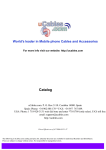
4.3
Configuration
CPU Configuration
WADE-8078 User’s Manual
4-3
BIOS Setup Information
Active Processor Cores
Number of cores to enable in each processor package
Choices: All, 1.
Intel Virtualization Technology
When enabled, a VMM can utilize the additional hardware capabilities provided by
Vanderpool Technology
Choices: Disable, Enable.
EIST
Enable/Disable Intel SpeedStep
Choices: Disable, Enable.
CPU C6 report
Enable/Disable CPU C6 (ACPI C3) report to OS
Choices: Disable, Enable.
Chipset configuration
High Precision Timer
Enable or Disable the High Precision Event Timer.
Choices: Disable, Enable.
WADE-8078 User’s Manual
4-4
BIOS Setup Information
Audio Controller
Control Detection of the Azalia device. Disabled = Azalia will be unconditionally
disabled. Enabled = Azalia will be unconditionally enabled. Auto = Azalia will be
enabled if present. Disable otherwise
Choices: Disable, Enable.
LAN Configuration
Launch Legacy PXE Rom
Launch Legacy PXE Rom. [Disable] Not launch Rom, [Enable] Force Launch Rom,
[Auto] Auto detect LAN Cable status to Enable/Disable Rom initial.
Choices: Disable, Enable, Auto
Wake On Lan Controller
Enable/Disable Intel Lan WGI210AT wakeup function.
Choices: Disable, Enable
WADE-8078 User’s Manual
4-5
BIOS Setup Information
Graphics Configuration
GOP Configuration
GOP Driver
Enable GOP Driver will unload VBIOS; Disable it will load VBIOS
Choices: Enable, Disable.
Intel IGD Configuration
IGD Turbo Enable
Enable: Enable IGD Turbo Enable. Disable: IGD Turbo Disable.
Choices: Enable, Disable.
Primary Display
Select which of IGD/PCI Graphics device should be Primary Display.
Choices: Auto, IGD, PCI, SG.
WADE-8078 User’s Manual
4-6
BIOS Setup Information
DVMT Pre-Allocated
Select DVMT 5.0 Pre-Allocated (Fixed) Graphics Memory sized used by the Internal
Graphic Device
Choices: 64M, 96M, 128M, 160M, 192M, 224M, 256M, 288M, 320M, 352M, 384M,
416M, 448M, 480M, 512M
DVMT Total Gfx Mem
Select DVMT 5.0 Total Graphic Memory size used by the Internal Graphics Device.
Choices: 128MB, 256MN, Max.
Primary UGFX Boot Display
Select the video device which will be activated during POST. This has no effect if
external graphics present. Secondary boot display selection will appear based on your
election. VGA modes will be supported only on primary display.
Choices: CRT, EFP.
LCD Panel Type
Select LCD panel used by Internal Graphics Device by selecting the appropriate setup
item.
Choices:VBIOS Default, 640x480 LVDS, 800x600 LVDS, 1024x768 LVDS, 1280x1024
LVDS, 1400x1050 (RB) LVDS, 1400x1050 LVDS, 1600x1200 LVDS, 1366x768 LVDS,
1680x1050 LVDS, 1920x1200 LVDS, 1440x900 LVDS, 1600x900 LVDS..etc.
Panel Scaling
Select the LCD Panel scaling option used by Internal Graphic device
Choices: Auto, Off, Force Scaling.
Backlight Control
Back Light Control Setting
Choices: PWM Inverted, PWM Normal, GMBus Inverted, FMBus Normal.
Active LFP
Select the Active LFP configuration.
Choices: No LVDS, Int-LVDS, SDVD LVDS, Edp Port-A, Edp Port-D
WADE-8078 User’s Manual
4-7
BIOS Setup Information
PCI/PCIE Configuration
PCI Express Configuration
WADE-8078 User’s Manual
4-8
BIOS Setup Information
PCI Express Root Port 0-3
Enable or Disable the PCI Express Port 0 in the Chipset.
Choices: Enable, Disable.
Speed
Configuration PCIe Port Speed.
Choices: Auto, Gen2, Gen1
SATA configuration
Serial-ATA (SATA)
Choices: Enable, Disable.
SATA Mode
Choices: IDE Mode, AHCI Mode.
SATA-ATA Port 0-1
Choices: Enable, Disable.
SATA Port 0-1 Hot Plug
Choices: Enable, Disable.
WADE-8078 User’s Manual
4-9
BIOS Setup Information
USB Configuration
USB Configuration settings
Legacy USB Support
Choices: Enable, Disable, Auto.
xHCI Legacy Support
Choices: Enable, Disable.
xHCI Hand-off
Choices: Enable, Disable.
EHCI Hand-off
Choices: Enable, Disable.
USB Mass Storage Driver Support
Choices: Enable, Disable.
WADE-8078 User’s Manual
4-10
BIOS Setup Information
USB Configuration
USB OTG Support
Enable/Disable USB OTG Support
Choices: Disable, PCI Mode, ACPI Mode.
USB VBUS
Choices: On, off.
XHCI Mode
Choices: Enable, Disable, Auto, Smart Auto.
USB Link Power Management
Choices: Enable, Disable.
USB Port #0~#3
Disable USB port
Choices: Disable, Enable
WADE-8078 User’s Manual
4-11
BIOS Setup Information
Power Control Configuration
Enable Hibernation
Enable or Disable system ability to Hibernate (OS/S4 Sleep State). This option may be
not effective with some OS.
Choices: Disable, Enable.
ACPI Sleep state
Select the highest ACPI sleep state the system will enter when the SUSPEND button is
pressed.
Choices: Suspend Disable, S3 (Suspend to RAM).
Restore AC Power Loss
Select AC power state when power is re-applied after a power failure.
Choices: Power off, Power On.
Wake on Ring Controller
Enable/Disable GPIO wake on ring function.
Choices: Disable, Enable.
WADE-8078 User’s Manual
4-12
BIOS Setup Information
TPM
TPM configuration
Security Device Support
Enabke or diacble BIOS support for security device. OS will not show security device.
TCG EFI protocol and INT1A interface will not be abailabe.
Choices: Disable, Enable.
Current Status Information
Security Device Support
Enabke or diacble BIOS support for security device. OS will not show security device.
TCG EFI protocol and INT1A interface will not be abailabe.
Choices: Disable, Enable.
WADE-8078 User’s Manual
4-13
BIOS Setup Information
Super I/O
Super I/On configuration
Serial Port
Enable or Disable serial port (COM).
Choices: Disable, Enable.
UART Mode
Set current UART MODE RS232, RS485, RS485/RS232 FULL DEFLEX.
Watch Dog Timer
Enable or Disable watch dog timer
Choices: Disable, Enable.
WADE-8078 User’s Manual
4-14
BIOS Setup Information
PC Health Status
Serial Port Console Redirection
WADE-8078 User’s Manual
4-15
BIOS Setup Information
COM 0-1 (Disable)
Console Redirection
Choices: Disable, Enable.
4.4
Security
Administrator Password
Set Administrator Password
User Password
Set User Password
WADE-8078 User’s Manual
4-16
BIOS Setup Information
4.5
Boot
Boot configuration
Setup Prompt Timeout
Number of seconds to wait for setup activation key. 65535(0xFFFF) means indefinite
waiting.
Choices: 0, 1.etc
Bootup NumLock State
Select the keyboard Numlock state
Choices: On, off.
Post Report
Post report support enable/disable
Choices: Disable, Enable.
Summary Screen
Choices: Disable, Enable.
CSM Support
Choices: Disable, Enable.
WADE-8078 User’s Manual
4-17
BIOS Setup Information
GateA20 Active
Choices: Upon Request, Always.
Option ROM Messages
Set display mode for option ROM
Choices: Force BIOS, Keep Current.
INI19 Trap Response
BIOS reaction on INT19 trapping by option ROM: IMMEDIATE – execute the trap
right away; POSTPONED – execute the trap during legacy boot.
Choices: Immediate, Postponed.
Storage
Controls the execution of UEFI and Legacy Storage opROM
Choices: Do not launch, UEFI only, Legacy only.
Fill Screen Logo
Enable or Disable quiet boot option and full screen logo
Choices: Disable, Enable.
OS Selection
Choices: Windows 8.X, windows 7.
Fast Boot
Enable or disable boot with initialization of a minimal set of devices required to
launch active for BBS boot options.
Choices: Disable, Enable.
Boot option priorities
Boot Option #1
Sets the system boot order
Choices: UEFI: Built-in EFI Shell, Disable.
WADE-8078 User’s Manual
4-18
BIOS Setup Information
4.6
Save & Exit
Save Changes and Reset
Reset the system after saving the changes
Disable Changes and Reset
Reset system setup without saving any changes
Restore Defaults
Restore/Load Default values for all the setup options
WADE-8078 User’s Manual
4-19
Troubleshooting
Chapter 5
Troubleshooting
This chapter provides a few useful tips to quickly get WADE-8078 running with
success. As basic hardware installation has been addressed in Chapter 2, this chapter
will primarily focus on system integration issues, in terms of BIOS setting, and OS
diagnostics.
5.1
Hardware Quick Installation
ATX Power Setting
Unlike other Single board computer, WADE-8078 supports ATX only. Therefore,
there is no other setting that really needs to be set up. However, there is 8 Pin ATX
Connector—CN1 in the WADE-8078 board.
Serial ATA
Unlike IDE bus, each Serial ATA channel can only connect to one SATA hard disk at a
time; The installation of Serial ATA is simpler and easier than IDE, because SATA
hard disk doesn’t require setting up Master and Slave, which can reduce mistake of
hardware installation.
The WADE-8078 can support two SATA interface (SATAII, 3.0 GB/s) with AHCI or
IDE mode. It has two J11 SATA ports in the board.
WADE-8078 User’s Manual
5-1
Troubleshooting
5.2
BIOS Setting
It is assumed that users have correctly adopted modules and connected all the
devices cables required before turning on ATX power. 204-pin DDR3 Memory,
keyboard, mouse, SATA hard disk, VGA connector, power cable of the device, ATX
accessories are good examples that deserve attention. With no assurance of properly
and correctly accommodating these modules and devices, it is very possible to
encounter system failures that result in malfunction of any device.
To make sure that you have a successful start with WADE-8078, it is recommended,
when going with the boot-up sequence, to hit “Del” key and enter the BIOS setup
menu to tune up a stable BIOS configuration so that you can wake up your system far
well.
Loading the default optimal setting
When prompted with the main setup menu, please scroll down to “Load Setup
Defaults”, press “Enter” and select “Yes” to load in default optimal BIOS setup. This
will force your BIOS setting back to the initial factory configuration. It is
recommended to do this so you can be sure the system is running with the BIOS
setting that Portwell has highly endorsed. As a matter of fact, users can load the
default BIOS setting any time when system appears to be unstable in boot up
sequence.
5.3
Q&A
Information & Support
Question: I forget my password of system BIOS, what am I supposed to do?
Answer: You can switch off your power supply then find the JP6 to set it from 1-2
short to 2-3 short and wait 5 seconds to clean your password then set it back to 1-2
short to switch on your power supply.
JP6:CMOS Setting
Jumper Setting Describe
*1-2
Normal
2-3
Clean CMOS
WADE-8078 User’s Manual
5-2
Troubleshooting
Question: How to update the BIOS file of the WADE-8078?
Answer:1. Please visit web site of the Portwell download center as below hyperlink
http://www.portwell.com.tw/support/download_center.php
But you must register an account first. (The E-Mail box should be an
existing Company email address that you check regularly.)
http://www.portwell.com.tw/member/newmember.php
2. Input your User name and password to log in the download center.
3. Select the “Search download” to input the keyword “WADE-8078”.
4. Find the “BIOS “page to download the ROM file and flash utility.
5. Execute the zip file to root of the bootable USB pen drive. You can get
the“Update.efi”,”Readme.txt” two files
WADE-8078 User’s Manual
5-3
Troubleshooting
6. Insert your USB pen drive in USB port of the WADE-8078 board and
power-on.
7. Boot to DOS mode then input the “fs0:” command to switch to the root of
the USB drive.
8. Type the” cd update” command to start flash BIOS processes.
9. When it finished all update processes, it will reboot in 5 seconds
automatically.
WADE-8078 User’s Manual
5-4
Troubleshooting
10. Please press the “Del” key to BIOS setup menu to select “Load Setup
Defaults” and then select “Exit Saving Changes” option to finish all BIOS
flash processes.
Question: How to install Windows 7 on the WADE-8078?
Answer:
Because of the WADE-8078 is Bay Trail platform, you have to adjust the XHCI
mode item from BIOS, but windows 8 or Linux OS doesn’t.
You must adjust the XHCI mode to [Smart Auto] from BIOS setup menu
before install windows 7.
Following this step, it can install the windows 7 OS successfully.
Note:
Please visit our Download Center to get the Catalog, User manual, BIOS, and driver
files.
http://www.portwell.com.tw/support/download_center.php
If you have other additional technical information or request which is not covered in
this manual, please fill in the technical request form as below hyperlink.
http://www.portwell.com.tw/support/problem_report.php
We will do our best to provide a suggestion or solution for you.
Thanks
WADE-8078 User’s Manual
5-5