1
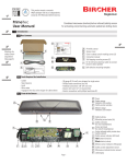
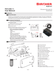
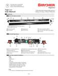
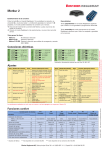
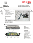
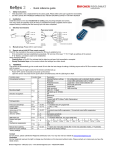
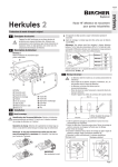
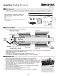
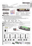
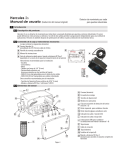
EN ISO
9001
Quality
Herkules 2
international
level
Microwave motion detector
for industrial doors
Translation of the original operation instruction
4
Safety instructions
1
The unit may only be operated from a protection low-voltage
system with electrical separation. The unit may only be opened
and repaired by the supplier.
Never touch any electronic components of the detector
5
If the device is already connected, interrupt the power supply for
5 seconds.
After mounting, activate the wide field with the remote control (B+1).
Addressing: Each detector can be assigned an address (1–4 with DIP
switch and 5–7 with remote control). Different addresses are necessary
when several detectors are within the range of a remote control.
Description of the detector
2
Adress 1*
Herkules 2
Microwave motion detector
for industrial doors
* Factory setting
Adress 2
Adress 3
3
Adress 4
7
Other addresses 5, 6 + 7 can be set using the remote control
(F+8+5…7)
TOP
5
1
8
3.2
Mechanical mounting
12
13
– The detector must be firmly mounted on a flat surface. (Avoid
vibrations)
– Objects such as plants, flags, fans etc. must not protrude into
the detection area.
– The detector must not be obscured by covers/signs
– Fluorescent lamps should not be placed in the immediate
vicinity of the detection area
– Mount the device in the middle above the industrial door
14
5
TOP
4
10
15
11
6
2
9
2
3
4
5
6
7
8
9
55 (2.17")
Housing
Front cover
Rear wall
Mounting bracket
Fastening
Cover screws
8-pin cable
Microwave planar module
Screw terminal
10
11
12
13
14
15
Key X
Key Y
Switch addressing
LED red
LED green
Clip
Before Mounting
3.1
Use the drilling jig enclosed
in the packaging!
73.5 (2.89")
Mounting
3
2")
(0.
5
Ø
13.5 (0.53")
1
Field geometry: Select whether a narrow or wide field geometry
should be used. The clip must be used for the wide field.
Note:The clip can be used for mounting heights up to max. 4 m.
It is not mounted on delivery. (However, it is stuck onto the rear of the
antenna.)
1. Affix drilling jig to wall or ceiling and drill holes according to values
given.
2. Route cable through opening provided in mounting bracket and
make sure length is sufficient for wiring.
3. Screw mounting bracket on tightly
4. Hook detector into mounting bracket and set detector to required
angle. Standard angle: 30°
5. Connect cable according to type plate.
Ceiling mounting:
Wall mounting:
125
min. 50
50
125
50
2
125
41
1
41
IMPORTANT:
Fit the clip correctly!
3
45
125
min. 50
45
Page 1
Configuration mode can only be activated with the remote control if a
code has been stored previously (see access code).
Electrical connections
3.3
white 12–28 V AC / 12–36 V DC
1. Press start key G
➔ G and one of the keys 1...7 light up
brown 12–28 V AC / 12–36 V DC
green
yellow
grey
pink
blue
red
Relay 1
48 V AC / DC
55 VA / 24 W
2. Press C then 9
➔ C and 1 light up
➔ Access code function is switched on
Relay 2
48 V AC / DC
55 VA / 24 W
4
Settings
4.1
Switching on and factory setting
3. Enter four-digit code 1111 - 9998
4. Press C
➔ C and 1 light up
➔ Configuration mode is activated
➔ Detector is ready for programming
➔ If C and 2 light up, code was incorrect
➔ Start again from step 1
After the supply voltage has been connected, the red LED signals
"Start-up" by flashing.
The factory setting is suitable for the following applications:
– Mounting height 4.0 to 4.9 m
– Relay hold interval 2 s
– Slow motion detection switched off
– Differentiation between people and vehicles active
– Crossing traffic optimisation switched off
– Detection of movements towards the detector (forwards)
4.4 Most important settings
1. Select enhanced level (C+1…8)
2. Set mounting height (F+4+1…7) if different from factory setting
Important: The detector will not function correctly if the
wrong mounting height is set
3. Set field size (D+1…9) if necessary using inclination angle, 0–90°,
in 15° steps
The factory settings can be restored at any time using the remote
control (A+9)!
+
Establishing the connection to the remote control
4.2
–
Infrared interface
+
Numerical keys
1 to 9
–
Battery
compartment
4.5
Locking
screw
Function keys
A to F
Start
Displays on the detector
Start-up phase
Red LED
G
Front side
Rear side
Press key G on the remote control. If the connection has been established successfully, G and one of the keys 1 to 7 light up (address of the detector).
Flashes several times during start-up, first slowly
then quickly.
Configuration
Green LED
Indicates the parameter (function no.) by the
frequency of flashing.
Red LED
Indicates the parameter level by the frequency of
flashing.
If G flashes, the connection could not be established.
Operation
➔ Hold the remote control closer to the detector and point directly at it.
➔ Check the batteries in the remote control.
General:
Flashing keys on the remote control mean that the Herkules 2 has not
stored the programming that has been performed.
Steady lit keys on the remote control mean that the value has been
accepted and stored by Herkules 2.
4.3 Configuration mode
The connection between the remote control and Herkules can only be
established when the detector is in configuration mode. Configuration
mode is activated when the detector is switched on. This is deactivated
automatically 30 minutes after the last setting has been made.
Configuration mode can be activated by:
– Pressing any key on detector (x or y)
– Interrupting electrical power supply
– Via access code on remote control
Page 2
Green LED
Green LED
Red LED
Lights up on detection, relay 2 is activated.
Flashes on detection in the SMD field.
Lights up on detection, relay 1 is activated.
Explanations
SMD = Slow Motion Detection
The slightest (quasi-static) movements are detected as soon as the
industrial door opens. The industrial door is only closed if no more
movement is registered during the set monitoring time.
CTM = Crossing traffic masking
Crossing traffic masking prevents an industrial door from being
inadvertently opened by objects that are only moving or walking past it
but do not want to pass through.
P/V identification
Using this function, it is possible to select whether the relay outputs
should be switched separately in response to people or vehicles (see
table of relay parameter settings).
Overview of settings
4.6
Enhanced functions (refer to chapter 5.9)
C+1
Standard
Keys
C+2
Frontal
Object detection
C+4
Sensitive
C+5*
Standard
All
Industrial door
type
Standard
Standard
Application
Standard
B: Wide field
D: Field size
E+1: Direction
recognition
C+3
High-speed
C+6
Frontal
C+7
High-speed
C+8
Sensitive
Person/vehicle identification, people suppression
Standard
Standard
Main traffic
frontal
High-speed
industrial door
High-speed
industrial door
Detects slow
objects
Standard
Level 2
Off
Level 2
Off
Level 2
Off
Level 2
Off
Level 2
Off
Level 2
Off
Level 2
Off
Level 2
Off
Level 6
Level 6
Level 6
Level 8
Level 6
Level 6
Level 6
Level 8
Level 1
forwards
Level 1
forwards
Level 1
forwards
Level 1
forwards
Level 1
forwards
Level 1
forwards
Level 1
forwards
Level 1
forwards
Level 5
R2: forwards
R1: backwards
Level 1
R2: Vehicle
R1: Person
Level 1
R2: Vehicle
R1: Person
Level 6
R2: Vehicle
R1: –
Level 1
R2: Vehicle
R1: Person
Level 5
Level 5
Level 8
E+2: Relay
R2: forwards R2: forwards
R2: forwards
parameterisation
R1: backwards R1: backwards R1: backwards
High-speed
industrial door
High-speed
Main traffic front
industrial door
Standard
Standard
Detects slow
objects
F1: Relay hold
interval
Level 4
2s
Level 4
2s
Level 4
2s
Level 4
2s
Level 4
2s
Level 4
2s
Level 4
2s
Level 4
2s
F3: SMD
Level 1
Off
Level 2
Weak
Level 1
Off
Level 8
Strong
Level 1
Off
Level 2
Weak
Level 1
Off
Level 8
Strong
F5: Cross traffic
Level 1
Off
Level 6
Medium
Level 1
Off
Level 2
Weak
Level 1
Off
Level 6
Medium
Level 1
Off
Level 2
Weak
F6: Digital filter
function
Level 2
Off
Level 2
Off
Level 2
Off
Level 2
Off
Level 2
Off
Level 2
Off
Level 2
Off
Level 2
Off
F7: SMD-field
Level 1
Small
Level 5
Medium
Level 1
Small
Level 5
Medium
Level 1
Small
Level 5
Medium
Level 1
Small
Level 5
Medium
From DIP
Switch
From DIP
Switch
From DIP
Switch
From DIP
Switch
From DIP
Switch
From DIP
Switch
From DIP
Switch
From DIP
Switch
F8: Adress
*factory settings
Relay parameter settings (refer to chapter 5.13)
E+2
1
Application
2
3
4
5
6
Standard
7
8
High-speed industrial door
Relay 2
(Green LED)
Relay 1
(Rod LED)
Switches in response to
vehicle
Switches in response
to person
Switches in direction
detection (E+1+1)
Switches in direction detection (E+1+1 or E+1+2)
Page 3
Configuration of individual parameters with «Reglobeam» remote control
Parameter
Key code
Request access code
C+9
Set Code
Enter Code
Delete Code
C+9
Address settings
F+8
Enhanced function
C
Mounting height
F+4
Field size
D
Relay hold interval
F+1
Direction recognition
E+1
Relay parameterisation
E+2
CTM
Crossing traffic masking
F+5
Wide field
B
Slow Motion Detection
F+3
SMD field size
F+7
Digital filter function
F+6
Manual industrial door opening
A
Exit configuration mode
Reset
A
A
5–7
9
1–8
1
2
3
4*
5
6
7
Short description
Code saved
No Code
Number from 1111–9998 and confirm with C
Enter selected code and confirm with C
Code deleted
interrogate target address
setting address 5–7
read in address from DIP-Switch
See table of enhanced functions
2.0 – 2.4 m
2.5 – 2.9 m
3.0 – 3.9 m
4.0 – 4.9 m
5.0 – 5.9 m
6.0 – 6.9 m
7.0 m
1–3
4–6*
7–9
1
2
3
4*
5
1*
2
3
Small
Medium
Large
0.2 s
0.5 s
1.0 s
2.0 s
5.0 s
Forwards
Backwards
Forwards and backwards
Level
Display 1
Display 2
XXXX+C
XXXX+C
9999+C
1*
2
3
4
5
6
7
8
1*
2–3
4–6
7–9
1
2*
1*
2
3
4
5
6
7
8
9
1*–3
4–6
7–9
1
2*
1
2
3
4
9
Standard industrial door, differentiation between people and vehicles
Standard industrial door, people suppression
Standard industrial door, vehicle suppression
Standard industrial door, people and vehicles, same output
Standard industrial door, people and vehicles, outputs with direction segregation
High-speed industrial door, people suppression
High-speed industrial door, people and vehicles, same output
High-speed industrial door, people and vehicles, outputs with direction segregation
Off
Low
Medium
High
On
Off
Off
0.5 s
1.0 s
1.5 s
2.0 s
0.5 s
1.0 s
1.5 s
2.0 s
Small
Medium
Large
On
Off
Switch off both relays
Switch on relay 1
Switch on relay 2
Decreasing sensitivity
Constant sensitivity
Avoidance of false tripping by fluorescent tubes
Reinitialise
* Factory setting
Page 4
5
5.1
5.5
Explanation of functions and settings
General description of the remote control
Press start key G on the Reglobeam
➔ If the connection has been established successfully, G and one of the
keys 1 to 7 light up (address of the detector)
➔ If G flashes, the connection could not be established
➔ Hold the remote control closer to the detector and point directly at it
➔ Check the batteries of the Reglobeam.
➔ Replace the batteries if nothing lights up.
➔ Configuration mode is not activated if G and one of the keys 1 to 7
light up although no further settings are possible.
The Reglobeam remote control allows you to program Herkules 2 easily
and conveniently from the ground. Data transfer between Reglobeam and
Herkules 2 functions in both directions, i.e. to and from the detector, and
is guaranteed by an infrared interface. The Reglobeam reads back the
adjusted values immediately after programming and displays them for
control purposes. This ensures safe and correct programming.
5.2
Function of the «Reglobeam» remote control
Please refer to the first part (4.6) for an overview of individual parameters
and the enhanced level settings.
The «Reglobeam» remote control functions using a combination of functions and number keys. Take care to operate it correctly as described in
chapter 4.2.
Flashing keys on the Reglobeam indicate that the data has not been fully
transmitted. Avoid exposing the infrared interface to direct sunlight or
other light sources.
5.3
Layout of the «Reglobeam» remote control
Establishing the connection
Note: Programming must be carried out within 30 s. If this time elapses,
it is necessary to activate programming mode again (press key G
5.6
Configuration with keys
Infrared interface
Numerical keys
1 to 9
Battery
compartment
Function keys
A to F
Start
Locking
screw
G
Front side
5.4
Rear side
Key
Key
X
Primary mode:
Press keys X and Y simultaneously and hold for 2 s
➔ Green LED lights up, then release
Secondary mode:
Press keys X and Y simultaneously and hold for 4 s
➔ Red LED lights up, then release
Reset:
Press keys X and Y simultaneously and hold for 8 s
➔ Both LED lights up, then release
Configuration mode
The connection between the Reglobeam and Herkules 2 can only be
established when the detector is in configuration mode. Configuration
mode is activated when the detector is switched on. For safety reasons,
this mode is automatically deactivated 30 minutes after the last setting
has been made on the detector. Configuration mode can be exited at any
time by pressing keys A+4.
Mode
Primary
Configuration mode can be activated in three different ways:
a) By pressing any key X or Y key on the detector
Sekundär
Key
Key
Y
Procedure
Press keys X and Y at the
same time to access the
required mode.
Y
X
b) By restarting the detector (disconnecting the supply voltage)
c) Access via remote control with access code
Parameter (key X)
Function no. Level key Y
Enhanced level
1
1–8
Mounting height
2
1–7
Relay parameter setting
3
1–8
Field size
4
1–9
Relay hold interval
1
1–5
Direction recognition
2
1–3
Crossing traffic masking
3
1–9
Wide field
4
1–2
SMD level
5
1–9
SMD field size
6
1–9
Digital filter function
7
1–2
Changing the function
Press key X. The value increases by 1 for every key press (function no.).
Once the last function has been reached, the program jumps back to the
first function. The green LED then indicates the number of the activated
function.
Changing the level
Press key Y. The value increases by 1 for every key press (level). Once the
last level has been reached, the program jumps back to the first level.
Exiting programming mode
Exit programming mode by pressing both keys X and Y briefly at the same
time.
Page 5
5.7
Adjusting the detector
The settings are identified as follows:
e.g. D+… Remote control menu
e.g. P.1… Primary programming mode with keys, function no. 1
e.g. S.3… Secondary programming mode with keys, function no. 3
5.8
Mounting height F+4
F + 4 + 1…7
P.2+1…7 (keys)
1 = 2.0 bis 2.4 m
2 = 2.5 bis 2.9 m
3 = 3.0 bis 3.9 m
4 = 4.0 bis 4.9 m
5 = 5.0 bis 5.9 m
6 = 6.0 bis 6.9 m
7 = 7.0 bis 7.9 m
5.13 Relay parameter settings E+2
Remote
Function
control
Standard industrial door, differentiation between
E+2+1
people and vehicles
E + 2 + 2 Standard industrial door, people suppression
E + 2 + 3 Standard industrial door, vehicle suppression
Standard industrial door, people and vehicles,
E + 2 + 4 same
output (relay 2)
Standard
industrial door, people and vehicles,
E + 2 + 5 outputs with
direction segregation
High-speed industrial door, people suppression
E+2+ 6
(relay 2)
High-speed industrial door, people and vehicles,
E + 2 + 7 same
output (relay 2)
High-speed
door, people and vehicles,
E + 2 + 8 outputs withindustrial
direction segregation
Keys
P.3 + 1
P.3 + 2
P.3 + 3
P.3 + 4
P.3 + 5
P.3 + 6
P.3 + 7
P.3 + 8
Please also refer to the table of relay parameter settings in point 4.6!
It is essential to adjust the mounting height if it does not match the
factory setting.
5.9
Comfort functions C
These pre-programmed settings allow you to configure the system
quickly and easily for standard applications.
Remote
control
C+1
C+2
C+3
C+4
C+5
C+6
C+7
C+8
Function
Keys
Standard, detects all objects
Frontal traffic, all objects
High-speed industrial door, all objects
Detects slow movements, all objects
Standard, differentiation between people and
vehicles
Frontal traffic, differentiation between people
and vehicles
High-speed industrial door, people suppression
P.1+1
P.1+2
P.1+3
P.1+4
Detects slow movements, differentiation
between people and vehicles
P.1+8
5.14 Crossing traffic masking CTM F + 5
CTM prevents an industrial door from being inadvertently opened by vehicles or persons that are only moving or walking past it but do not want to
pass through the industrial door.
F + 5 + 1 = Aus
F + 5 + 2…9
S.3 + 1
S.3 + 2…9
Industrial door remains closed
to crossing traffic (level 9)
P.1+5
P.1+6
Industrial door opens to crossing traffic
or when an object approaches laterally
(level 1)
P.1+7
Note: The selected enhanced function is only read back and displayed
as such if no parameters were changed. Please refer to the table of
enhanced functions in 4.6 for more details.
Optimum inclination angle for crossing traffic function: 30° to 45°
Crossing traffic masking is not possible with the clip!
5.15 Wide field B
5.10 Field size D
B + 1 = On
B + 2 = Off
D + 1…9
P.4+1…9 (keys)
Levels 1 (small field) to 9 (large field)
Refer to the technical data for field dimensions.
S.4 + 1
S.4 + 2
Field without clip
Field with clip
5.11 Relay hold interval F+1
F + 1 + 1…4
S.1 + 1…5 (keys)
1 = 0.2 s
2 = 0.5 s
3 = 1.0 s
4 = 2.0 s
5 = 5.0 s
The relay hold interval only starts after other functions have been completed (delayed).
This option must be activated when the mechanical clip is used for setting a wide field. Please refer to 3.1 for information about clip mounting.
The detector will not function correctly if the wrong setting is made.
5.12 Direction recognition E+1
5.16 Slow Motion Detection (SMD) F+3
Page 6
Remote
control Function
Keys
E + 1 + 1 Forwards, movement towards detector
E + 1 + 2 Backwards, movement away from detector
E + 1 + 3 Forwards and backwards
S.2 + 1
S.2 + 2
S.2 + 3
The slightest (quasi-static) movements are detected as soon as the detector is activated. The detector only issues the corresponding signal to the
industrial door controller if no more movement is registered during the set
monitoring period. Sensitivity during this monitoring period can be set to
decrease or remain constant.
Keys
F+3+1
F + 3 + 2…5
F + 3 + 6…9
S.5 + 1
S.5 + 2… 5
S.5 + 6… 9
Off
Decreasing sensitivity
Constant sensitivity
Additional SMD field
SMD-Field
Detektion area
5.17 Special settings
Manual industrial door opening
A+1=
A+2=
A+3=
A+4=
Both relays off
Relay 1 on
Relay 2 on
Both relays off, exit configuration mode
Reset A+9
This function resets all device parameters to the factory settings (see 4.1)
and a new initialisation phase starts as if the device had been switched
on again.
The reset also deletes the access code. There are two possible ways of
resetting the device to its factory settings:
1) With the remote control
A + 9 = Reset
2) With the keys:
Press keys X and Y simultaneously and hold for 8 seconds.
Every 2 seconds, both LEDs light up briefly. Both LEDs light up after 8
seconds. The reset is performed when the keys are released.
Access code
Herkules 2 can be protected against unwanted manipulation by means of
a four-digit access code. This code enables configuration mode to be
reactivated at any time by remote control in order to perform settings.
This function is inactive by default.
Switching on access code:
The code can only be stored if the detector is already in configuration
mode. The device is protected as soon as the code has been stored.
(Configuration mode is deactivated)
1. Press start key G
➔ G and one of keys 1...7 light up
2. Press C then 9
➔ C and 2 light up
➔ The access code function is switched off (no code stored)
3. Enter the 4-digit code (any number between 1111 – 9998)
4. Press C
➔ C + 1 lights up
➔ The access code function is switched on (code stored)
Configuration mode is deactivated (device is protected).
Configuration mode is activated when the detector is switched on. This is
deactivated automatically 30 minutes after the last setting has been
made.
Configuration mode can be activated by:
– Pressing any key on detector (x or y)
– Interrupting electrical power supply
– Via access code on remote control
Configuration mode can only be activated with the remote control if a
code has been stored previously (see access code)
1. Press start key G
➔ G and one of keys 1...7 light up
2. Press C then 9
➔ C and 1 light up
➔ Access code function is switched on
3. Enter four-digit code 1111 – 9998
4. Press C
➔ C and 1 light up
➔ Configuration mode is activated
➔ Detector is ready for programming
➔ If C and 2 light up, code was incorrect
➔ Start again from step 1
Switching off access code function (deleting code) without
remote control
Press both keys X and Y simultaneously and hold for 8 seconds. Both
LEDs light up briefly every 2 s.
➔ Device is reset to factory settings
➔ Access code function is switched off
➔ (Code deleted)
➔ New initialisation and teach-in phase starts (see 4.1)
Digital filter function
In special mounting situations, it might be necessary to activate the
filter function under certain circumstances. Sources of interference
located close to the detector can lead to malfunctions.
F + 6 + 1 = On
S.7 + 1
F + 6 + 2 = Off
S.7 + 2
Addressing Herkules 2
Seven different addresses for communication with the Reglobeam
remote control can be set on the Herkules 2.
Addresses 1 – 4 are set using the built-in DIP switch.
Switch adressing
Switching off access code:
The code can only be deleted if the detector is already in configuration
mode.
1. Press start key G
➔ G and one of keys 1...7 light up
2. Press C then 9
➔ C + 1 light up
➔ Access code function is switched on
3. Press 9 four times, then press C
➔ C and 2 light up
➔ The access code function is switched off (code deleted)
Activating configuration mode
The connection between the remote control and Herkules can only be
established when the detector is in configuration mode.
Adress 1*
Adress 2
Adress 3
Adress 4
* Factory setting
Remote Control Function
Addresses 5 – 7 are set using the remote control.
F + 8 + 5 = Adress 5
F + 8 + 6 = Adress 6
F + 8 + 7 = Adress 7
F + 8 + 9 = Read in set address from DIP switch
Different addresses should be set if detectors are mounted next to or
opposite to one another and are within range of the same remote
control.
Page 7
Troubleshooting
6
Symptom
Possible cause
Remedy
Industrial door reverses
Detector detects industrial door
Change the inclination angle of the
microwave module
Refer to chapter
4.4
Industrial door opens – false tripping
Interference source affects
microwave field (e.g. fluorescent
tubes)
Activate the interference suppression filter
(F6+1)
5.17
Late detection or non-detection of
persons
Field is too small, incorrect mounting height set
Check the field size (D1…9).
Set the correct mounting height (F4+1…7).
Check setting for wide field.
5.10
5.8
5.15
P/V identification does not function
Incorrect mounting height entered
Set the correct mounting height (F4+1…7).
Check setting for wide field.
5.8
5.15
Technical data
8
Technology
Doppler radar with planar module
Transmitting frequency
24.05–24.25 GHz
Transmitting power
< 20 dBm
Operating voltage
12–28 VAC, 12–36 VDC
Operating current
max 75 mA
Mains frequency
50 Hz
Temperature range
Mounting height
–30° bis 60° C
0% to 95% relative, without
condensation
2.0 bis 7 m
Relay outputs
Potential-free changeover contacts
Switching voltage
max 48 VAC/DC
Switching current
max 0.5 A AC
Housing
Aluminium schwarz eloxiert,
Deckel Polycarbonat
Dimensions
134 x 82 x 75 mm
Weight
Protection class
(EN 60529)
Max. detection speed
720 g inkl. Kabel
Cabel
Length 5 m, 8 x 0.14 mm2
Approvals
Suitable for the following
countries
Field dimensions with 30°
inclination
CE 0682 ! / FCC / IC
Air humidity
IP 65
25 km/h für Fahrzeuge
EU, EFTA, US, CA
FCC approval
This device meets the requirements of Part 15 of the FCC regulations and the RSS210 standard of Industry Canada.
Operation is subject to the following two conditions:
• this device may not cause harmful interference, and
• this device must accept any interference received, including interference that
may cause undesired operation.
This equipment has been tested and found to comply with the limits for a Class B
digital device, pursuant to part 15 of the FCC Rules. These limits are designed to
provide reasonable protection against harmful interference in a residential installation. This equipment generates, uses and can radiate radio frequency energy
and, if not installed and used in accordance with the instructions, may cause
harmful interference to radio communications. However, there is no guarantee
that interference will not occur in a particular installation. If this equipment does
cause harmful interference to radio or television reception, which can be determined by turning the equipment off and on, the user is encouraged to try to correct
the interference by one or more of the following measures:
• Reorient or relocate the receiving antenna
• Increase the separation between the equipment and receiver
• Connect the equipment into an outlet on a circuit different from that to which
the receiver is connected
• Consult the dealer or an experienced radio/TV technician for help
Warning: Changes or modifications made to this equipment not expressly approved by Bircher Reglomat AG may void the FCC authorisation to operate this equipment.
from 2.5 m x 3 m (WxD) height 2 m
to 5 m x 7 m (WxD) height 7 m
Warranty and liability
Bircher Reglomat AG herewith declares the product Herkules 2 to be in
conformance with the basic requirements and other relevant regulations
as contained in the 1999/5/EC Directive.
The full version of the Declaration of Conformity can be viewed on our
internet homepage:
www.bircher-reglomat.com
Page 8
Your contact:
Bircher Reglomat AG
Wiesengasse 20
CH-8222 Beringen
Switzerland
Telefon +41 52 687 11 11
Telefax +41 52 687 11 12
[email protected]
www.bircher-reglomat.com
10/08
EU Declaration of Conformity
and any damage caused by other reasons, for which Bircher Reglomat AG cannot be
held liable.
4. No liability can be assumed for any consequential damage, provided this is not governed otherwise by applicable product liability laws and regulations.
5. Warranty claims made against the seller on the basis of the sales agreement are not
affected by these regulations.
6. For the benefit of its customers Bircher Reglomat AG constantly develops its products further. Bircher Reglomat AG reserves the right to make changes to any of the
products described in this document without prior notice.
6992-06-0034 a
1. The warranty and liability of Bircher Reglomat AG are based on the sales
contract.
2. The warranty and liability shall expire prematurely, should the client or third
parties not use and/or operate the product in compliance with existing operating instructions, should incorrect changes or repairs be made by the client or
third parties, should the client or third parties, when a fault has occurred, not
take suitable steps at once for a reduction of possible damage/losses and offer Bircher Reglomat AG a chance for remedying the said fault.
3. The warranty and liability shall exclude any damage for which there is no
proof that it is due to poor materials, faulty construction, poor workmanship,