1
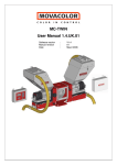
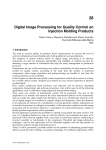
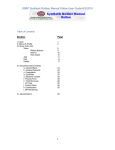
Gravimetric Masterbatch Feeder Operation and Installation Manual Part Number: 882.01793.00 Bulletin Number: BF3-605 Effective: 4/4/11 Table of Contents 1.0 Introduction ........................................................................................................................ 4 2.0 Product overview ............................................................................................................... 5 2.1 Feeding system .............................................................................................................. 5 2.2 Dosing screws ................................................................................................................ 6 2.3 Control unit ..................................................................................................................... 6 3.0 Installation .......................................................................................................................... 7 3.1 General safety notes and warnings ............................................................................ 7 3.2 Mechanical installation .................................................................................................. 7 3.2.1 Mounting to the injection-molding machine throat (see Fig. 2) ..................... 7 3.2.2 Releasing the load cell .......................................................................................... 8 3.2.3 Venturi loader installation (see Fig. 2) ............................................................... 8 3.2.4 Control unit mounting ........................................................................................... 8 3.3 Electrical installation ..................................................................................................... 9 3.3.1 Connect the following (see Fig 5: Connections diagram): .............................. 9 3.3.2 "Sensor" cable wiring options: ........................................................................... 10 4.0 Operation .......................................................................................................................... 11 4.1 General .......................................................................................................................... 11 4.1.1 Operation Modes .................................................................................................. 11 4.1.2 MB feeding modes: .............................................................................................. 12 4.2 Display and control panel ........................................................................................... 13 4.3 Starting sequence ........................................................................................................ 14 4.3.1 Main Screen for Mode "0" (Gravimetric Mode)................................................ 14 4.3.2 Main Screen for Mode "1" (Gravimetric Mode, with constant feeding time) .......................................................................................................................................... 14 4.3.3 Main Screen for Mode "2" (Volumetric Mode) ................................................. 15 4.3.4 Main Screen for Mode "3" (Volumetric Mode, with constant AF-1000 feeding time)................................................................................................................... 15 4.4 Configuration Parameters setup................................................................................ 16 4.4.1 ................................................................................................................................. 16 4.4.2 Setting installed screw number.......................................................................... 16 4.4.3 Setting desired Operation Mode ........................................................................ 17 4.4.4 Setting Max/Min AF-1000 Hopper Weight Parameters ................................ 17 4.4.5 Gravimetric/Volumetric switch ........................................................................... 17 4.5 Process data parameters setup ................................................................................. 18 4.5.1 Entering Process Data parameters in Mode "0" .............................................. 18 4.5.2 Process Data parameters in Mode "1" .............................................................. 18 4.5.3 Process Data parameters in Mode "2" .......................................................... 18 4.5.4 Process Data parameters in Mode "3" .............................................................. 19 4.6 Accumulated data display .......................................................................................... 20 4.7 Failure alarms............................................................................................................... 21 4.7.1 “Fill” Alarm ............................................................................................................ 21 4.7.2 “Over/Under Speed (dose)” Alarms .................................................................. 21 4.7.3 “Calibration failure” Alarms................................................................................. 22 4.7.4 Feed Deviation Alarm .......................................................................................... 22 4.7.5 Alarm Output (J2) ................................................................................................ 23 5. Maintenance ....................................................................................................................... 24 BF3-605 2 5.1 Static calibration .......................................................................................................... 24 5.2 Emptying and cleaning ............................................................................................... 24 5.3 Replacing the dosing screw ....................................................................................... 24 5.4 Emptying / Refilling the feeding screw .................................................................... 25 5.5 Moving feeder to another injection machine or replacing controller................... 25 5.6 Trouble shooting.......................................................................................................... 26 5.7 Special Control parameters ........................................................................................ 28 5.8 Communication Option ............................................................................................... 28 6.0 Technical data .................................................................................................................. 29 6.1.Technical features ....................................................................................................... 29 6.2 Environmental conditions:.......................................................................................... 30 Appendix A: Load cell protection device......................................................................... 31 Appendix B: Static calibration .............................................................................................. 33 Appendix C: EC-Declaration of Conformity ....................................................................... 37 BF3-605 3 1.0 Introduction AEC AF-1000 is a single-component, gravimetric MB/ADD feeder for plastic injectionmolding machines. During normal operation, the device controls the weight of the MB/ADD fed into the injection machine with each injection shot, using the loss-in-weight method. By continuously measuring the weight of the material in the additive hopper, the system immediately detects any deviation from the preset MB/ADD weight, and automatically corrects to the required dosing, by regulating the current (rpm) of the dosing-feeding screw. If required, the feeder can operate in “constant” (non-regulated) current mode: the motor works at a pre-selected current (rpm), without being regulated by the controller according to fluctuations in the batch weight. The MB/ADD is fed directly into the injection machine’s feeding throat through a neckpiece adapter. The AEC AF-1000 can be delivered with 4 standard alternative screws, for low and high dosing ranges. Selection of the correct screw yields very high accuracy. The feeder is equipped with an integral Venturi loader, which automatically refills the Masterbatch/Additive hopper whenever its contents fall below a predefined minimum weight. The feeder’s entire operation is automatically controlled by a powerful, sophisticated, yet easy-to-operate control unit. Important notes: This manual has been written to enable operators to use the machine correctly. Always keep the manual at hand and always follow the instructions. The operator is completely responsible for the operating safety of the system, and therefore all operators must have full knowledge of how to use it properly. Any use in a manner not specified in the user manual or any attempt by the user or non-authorized personnel to disassemble or modify the machine shall render the warranty invalid and the manufacturer shall not be responsible for any damage to persons or property. The equipment must be installed only by skilled personnel who have read and understood this manual. AEC is not responsible in any way for the quality of the products produced by the injection machine on which AEC equipment has been installed. Product quality is the sole responsibility of the customer. All technical data contained in this manual are the exclusive property of AEC Weighing and Control Systems Ltd. and must be considered as confidential. Therefore no reproduction or publication of this handbook, or any part thereof, is allowed without written authorization by the manufacturer. Moreover, this handbook shall not be used for purposes other than those connected to installation, use and maintenance of this equipment. BF3-605 4 2.0 Product overview 2.1 Feeding system Fig. 1: General View and Dimensions Fig. 2: Mechanical Details 1) 2) 3) 4) 5) 6) 7) 8) 9) 10) 11) BF3-605 Main bulk hopper Neckpiece top flange Neckpiece Bridge Sight glass Neckpiece bottom flange Injection machine throat Mounting flange Dosing screw Emptying aperture Gear 12) 13) 14) 15) 16) 17) 18) 19) 20) 21) DC motor Load cell protection device Load cell Additive/Masterbatch hopper Quick release latch Additive/Masterbatch loading inlet Flexible loading pipe Venturi suction tube Pneumatic air inlet Additive/color container 5 2.2 Dosing screws The following alternative screws are available: Screw No A) Micro-Cap Dosing screw 0 B) Low-Cap dosing screw: 2 pellets/shot to 0.2 kg/h 0.1 – 3.5 kg/hr C) Medium-Cap dosing screw: 0.4 – 10 kg/hr 2 D) High-Cap dosing screw: 0.6 – 20 kg/hr 3 E) Extra-Cap dosing screw: 1.0 – 35 kg/hr 4A 1 Notes: a) Indicated capacities are typical for normal materials, 0.7 gr./cm3 bulk density b) The identification numbers of the screws are marked on each screw. c) Two types of dosing screw #1 are available: 1.1 Standard low capacity screw 1.0 Special low capacity screw for particular materials 2.3 Control unit Fig. 4: Rear view Fig. 3: Front view Control panel + Display Switch: Gravimetric/Volumetric 6 J1: J2: J3: J4: J5: P1: S1 Load cell input Alarm output Injection cycle synchronizing input Communication port (optional) DC motor control output Pneumatic valve On/Off: Power inlet unit 3.0 Installation 3.1 General safety notes and warnings This manual contains all information required for installation. Subjects include mounting, connection, assignment of parameters, and a description of the interface and indicator elements. Adherence to these safety notes is mandatory. Non-compliance will invalidate your warranty. When you receive the equipment, check whether any damages were incurred during transport. If this is the case, please consult your agent before installation. Warning Persons who are not qualified should not be allowed to handle this equipment/system. Noncompliance with the installation and operation instructions can result in severe personal injury or substantial property damage. Only qualified personnel should be allowed to work on this equipment/system. In order to avoid an electric shock, make sure that you first make all necessary connections, before connecting the equipment to the mains. Also, make sure that the line is protected by effective short-circuit and over-voltage devices, and any other means required to protect the operator, and that there is an effective earth (ground) connection to the device. Caution: The motor has a permanent magnetic field. Never exceed Imax (6A). Any installation, maintenance and repair intervention must be performed only by skilled personnel, and only when the equipment/system is disconnected from the power supply mains. 3.2 Mechanical installation 3.2.1 Mounting to the injection-molding machine throat (see Fig. 2) a) Drill the top (2) and bottom (6) flanges of the neckpiece (3) to fit the flanges of the main hopper (1) and the feeding throat (7) of the injection machine. b) Install the neckpiece in its place, between the main hopper and the injection machine’s feeding throat and fasten it with its screws. c) Connect the feeder to the mounting flange (8) and fasten it with the quick-release star knob. 7 3.2.2 Releasing the load cell (see Appendix A) When the unit leaves the factory, the load cell is locked by its protecting device, to prevent any damage to the load cell during transportation and installation. After installation and before starting to operate the feeder, release the limiting pin of the protecting device from its "locked position" to "unlocked position"; otherwise the load cell will not be able to function. See Appendix A for unlocking instructions after installation. Important: Always re-lock the safety device whenever the AEC AF-1000 is dismantled from the injection or extrusion machine and being moved to another location or machine. Note that there is no guarantee for the load cell for any mechanical damage, or damage caused by an overload. 3.2.3 Venturi loader installation (see Fig. 2) a) Connect the Venturi suction tube (19) to the feeder’s additive/color loading inlet (17) with the flexible 25 mm dia. loading pipe (18). Note: The maximum pipe length should not exceed 3 meters and the maximum difference between the end of the Venturi suction tube and the top of the feeder-loading inlet should not exceed 2.5 meters. b) Connect the pneumatic air inlet (20) of the Venturi tube to the air outlet of the Air valve (P1) on the back panel of the controller. c) Connect a 6-8 AT air supply to the air inlet of the Air valve of the controller. d) Dip the Venturi suction tube into the main color/additive container (21). Verify that the tube is straight and not twisted or bent; otherwise it might disturb the suction process. 3.2.4 Control unit mounting Fix the control unit by its mounting arm in one of the following options: Option A (bottom surface): Option B (top surface): 8 3.3 Electrical installation 3.3.1 Connect the following (see Fig 5: Connections diagram): a) Connector J1-"Load cell" input, to the load cell (“Load cell” cable). b) Connector J2-"Alarm" output, to the alarm device (“Alarm” cable). c) Connector J3-"Sensor" input to the Injection machine (“Sensor” cable). Notes: 1) For connection options for this cable, see Chap. 3.3.2 "Sensor cable wiring options" 2) When the "Micro" (Pellet Counting) option is integrated, the cable is split into two cables – one from the injection machine (supplying the IMM signals) and the other one from the revolution sensor (supplying the "screw revolutions" data). d) Connector J4-Communication port to required device (optional) e) Connector J5-Motor control outlet to the motor cable (“Motor” cable). f) Connector 230V to the mains. Note: Good grounding of the injection machine is required to ensure proper feeder operation. Warning Do not connect or disconnect the motor cable when the power is "on" Fig 5: Connections diagram 9 3.3.2 "Sensor" cable wiring options: There are two alternatives for wiring the "Sensor" cable to the injection machine (see Fig 6): Alternative A (Standard): Connecting the "Filling" wire (black) and the "Common" wire (red) to a "Filling" dry contact in the injection machines, which is synchronized with the Filling phase – indicating the Recovery phase time (machine's screw backward motion). Using this standard wiring will ensure only the synchronization of the AEC AF-1000 operation to the injection machine's cycle time, and MB feeding during the Filling (Backward motion) time. Alternative B (Optional): Connecting the "Injection" wire (Green) to another dry contact which is synchronized with the Injection phase – indicating the Plasticizing/Injection time (screw's forward motion). This optional wiring will cause feeding of MB both during the Filling phase and (a certain amount) during the Injection phase as well, thus enabling better color dispersion. Notes: a) The "Filling" contact should be always connected in both alternatives A and B. The "Injection" contact should be connected only when a MB feeding is required during injection phase as well. b) The contacts should be No Voltage Contacts (Dry contacts) only. Fig 6: "Sensor" cable connections diagram 10 4.0 Operation 4.1 General The AEC AF-1000 adjusts itself automatically once new process data - product weight and required additive percentage - is entered into the controller. 4.1.1 Operation Modes The device can operate in four (4) pre-selected operation modes: 1. Mode "0"- Gravimetric loss-in-weight operation mode (regulated speed/machine feeding time) The motor speed is regulated on-line by the controller according to the required dosing rate, while the feeding time is determined by a signal (dry contact) from the injection machine, synchronized with the injection cycle, as the average value of the last injection shots (see notes). 2. Mode "1"- Gravimetric loss-in-weight operation mode (regulated speed/constant set feeding time): The motor current is regulated on-line by the controller according to the required dosing rate, while the feeding time is constant, as set by the operator. Start time is synchronized with the injection cycle by a signal (dry contact) from the injection machine. This mode is useful in those cases where the feeding time of the injection machine is not steady enough, too short, or too long. 3. Mode "2"- Volumetric operation mode (constant speed/machine feeding time): The motor speed (rpm) is kept constant, as set by the operator, independent of any variation in the process parameters, while the feeding time is defined by a signal (dry contact) from the injection machine, synchronized with the injection cycle (see note). 4. Mode "3" - Volumetric operation mode (constant speed / constant time) Two alternatives (sub-modes) are available: 1. Standard Volumetric mode: Both speed and time are constant, as set by the operator. This mode is applicable if any one of screws 1-4 is selected (not the micro). 2. Micro Volumetric mode: Operator sets motor speed and desired number of screw revolutions per injection cycle according to required batch weight (instead of feeding time, as in standard mode 3). This mode is applicable only if micro screw (No "0") is installed and selected. Using this mode enables very low dosing level, up to 2-3 granules per shot. Possible operation modes are shown in the following table: Operation Mode Dosing Time 0 Gravimetric Equal to IMM feeding time 1 Gravimetric Set by operator 2 Volumetric Equal to IMM feeding time Set by operator Motor Speed Revs/INJ shot Controlled automatically by MB % Controlled automatically by MB % Set by operator Volumetric Set by operator Standard 4 Volumetric Micro Set by operator Set by operator For more information concerning selecting the correct operation mode, see section 4.4 3 11 Applicable screws 0,1,2,3,4 0,1,2,3,4 0,1,2,3,4 1,2,3,4 0 (micro) 4.1.2 MB feeding modes: There are two alternative MB feeding modes, depending on the wiring of the "sensor" cable to the IMM (see Chap. 3.3.2): Alternative A (Standard): MB is fed only during the filling (backward motion of the IMM screw) phase Alternative B (Optional): MB is fed mainly during the filling (backward motion) phase; however, a certain quantity of MB will be fed during the injection (forward motion) phase as well. This option enables better color dispersion. Notes: a) Timing and time duration of each phase is identified by the AEC AF-1000 controller by the sensor input (when the relevant dry contacts in the injection machine are in "Closed" state). b) The initial feeding rate during the "filling" phase is determined by the controller according to the entered parameters (part weight and MB percentage) and the measured filling time, while the feeding rate during the "injection" phase (if selected), is a constant percentage of the dosing rate during the "filling" phase (can't be controlled by the operator). c) Feeding during the "injection" phase, if applied, will be performed in all 4 operation modes. d) The start of the "constant time" in modes 1 and 3 is synchronized always with the start of the "filling signal" (and not with the "injection signal"). 12 4.2 Display and control panel The control panel is composed of: Graphic screen for display of the set and measured values Numeric keyboard for selecting functions and entering set values Control keys for entering selecting screens and entering or changing parameters Use to selecting parameters or data before modifying them. Press the key again, without pressing <ENT>, to move selection to next parameter while leaving the parameter value unchanged Use to make new value valid and to select next parameter Use to cancel a change before <ENT>, or to return to Main screen Use to clear stored cumulative data Use to show existing alarms in detail - Use to move to different screens or select specific digit while entering/modifying current data 13 4.3 Starting sequence Switch on the Power main switch At first the initial screen will be displayed, showing the present control software and language versions now in use Enter Maintenance Screen (see 4.4) and press key if you wish to check the Version No. again later during operation Press <ESC> key to return to main screen Note: If the hopper is empty, the Venturi loader will perform an automatic filling sequence soon after the first operating, unless the MB % has been set to "0". After a few seconds, the “Main Screen” will be displayed. Main screen view depends on current selected Working Mode: 4.3.1 Main Screen for Mode "0" (Gravimetric Mode) Shot Weight: Injected batch weight, including the cold runner (gr.) Desired: Desired MB/Additives % Actual: Measured MB/Additives % Speed: Motor Speed in % of max. rate Weight: Weight of material in AF-1000 hopper (gr.) Press key to enter Totals screen Press key to enter Maintenance screen Press key to enter Fill / Empty screen 4.3.2 Main Screen for Mode "1" (Gravimetric Mode, with constant feeding time) 14 Shot Weight: Injected batch weight, including the cold runner (gr.) Desired: Desired MB/Additives % Actual: Measured MB/Additives % Speed: Motor speed in % of max. rate Weight: Weight of material in AF-1000 hopper (gr.) Press key to enter Time selecting screen, to manually set constant feeding time Press key to enter Maintenance screen Press key to enter Fill / Empty screen 4.3.3 Main Screen for Mode "2" (Volumetric Mode) Shot Weight: Injected batch's weight, including the cold runner (gr.) Desired: Desired MB/Additives % Actual: Measured MB/Additives % Machine time: Injection machine material feeding time Speed: Motor Speed in % of max. rate, as manually set by operator Press key to enter Speed selecting screen, to manually set constant Motor Speed time Press key to enter Maintenance screen Press key to enter Fill/Empty screen 4.3.4 Main Screen for Mode "3" (Volumetric Mode, with constant AF-1000 feeding time) a) Standard Volumetric Mode 3 (when screws 1-4 are selected) Shot Weight: Injected batch's weight, including the cold runner (gr.) Desired: Desired MB/Additives % Actual: Measured MB/Additives % AF-1000 Time: Injection machine material feeding time Speed: Motor Speed in % of max. rate, as manually set by operator Press key to enter Time/Speed selecting screen, to manually set Feeding Time and Motor Speed Press key to enter Maintenance screen Press key to enter Fill/Empty screen b) Micro Volumetric Mode 3 (when screw "0" is selected) 15 Shot Weight: Injected batch's weight, including the cold runner (gr.) Desired: Desired MB/Additive's % Actual: Measured MB/Additive's % Machine time: Injection machine material feeding time Speed: Motor Speed in % of max. rate, as manually set by operator Press key to enter Rev/Speed selecting screen, to manually set motor revolutions/shot and Motor Speed Press key to enter Maintenance screen Press key to enter Fill/Empty screen 4.4 Configuration Parameters setup 4.4.1 Set general working configuration parameter values - dosing screw type, operation mode and hopper Max/Min Fill - before entering the specific job parameters. While in Main screen: Press Press <4> key to enter Parameters screen key to enter Maintenance screen Use the following setting procedure to enter or modify any of the 4 parameters: <SET> Select desired parameter. The parameter value field will be marked. Enter (by keyboard) desired new value, and press <ENT> to make new value active. The next parameter will be selected. If you want to switch to next parameter without modifying the present value, press <SET> without pressing <ENT> Pressing <ESC> twice at any time will return you to the Main Screen 4.4.2 Setting installed screw number Each dosing screw is marked by its identifying number: "0" – Micro capacity 2 pellet/shot to 0.2 kg/h "1" - Small capacity 0.1 – 3.5 kg/h* "2" – Medium capacity 0.4-10 kg/h "3" – High Capacity 0.6 – 20 kg/h "4" – Extra high capacity 1.0 – 35 kg/h *There are two types of screw #1: "1.1" Standard low capacity "1.0" Special low capacity 16 To change screw number, return to Parameters screen, select the Screw line and set the new installed Screw number (using setting procedure described in 4.4.1) Proceed with other parameters or press <ESC> to return to Main Screen 4.4.3 Setting desired Operation Mode Available operation modes are: "0" – Gravimetric mode (with machine feeding time) "1" – Gravimetric mode (with AF-1000 constant time) "2" – Volumetric mode (with machine feeding time) "3" – Volumetric mode (with AF-1000 constant time) To change mode, enter Parameters screen, select the Mode line and set the new desired Mode number (using setting procedure described in 4.4.1) Proceed with other parameters or press <ESC> to return to Main Screen 4.4.4 Setting Max/Min AF-1000 Hopper Weight Parameters Once the weight of the material in the hopper decreases below "Minimum hopper weight" set low limit, the controller instructs the Venturi loader to start refilling the hopper. The refilling operation will continue either until material weight reaches "Maximum hopper weight" high limit set value, or until 60 seconds have passed (whichever comes first). If, for some reason, the MB/Additive weight in the hopper stays under the Min Fill low limit value for more than 120 seconds, despite the filling operation, an “Alarm” screen will be displayed, indicating a “No fill” situation (see note 1). Factory setup values (default values) are 1100g for "Max Fill" and 400g for "Min Fill". The user may either leave this as it is or change it according to specific needs. To change changing current Minimum or Maximum hopper weight value, enter "Parameters" screen, select the Minimum or Maximum hopper weight line and set the new desired value (using setting procedure described in 4.4.1) Press <ESC> to return to Main Screen Notes: 1. If desired MB % has been set to "0", there will not be an automatic filling, even when the material weight reaches Min Fill level. 2. Level values should be always set so that Min weight < Max weight. 3. When first starting the controller (by switching on the power), if the hopper is empty or its material weight is under the Min Fill value, the Venturi loader will perform automatic filling (unless the MB/Additive % is set to "0"). 4.4.5 Gravimetric/Volumetric switch (located on front panel): Allows you to switch easily from any mode to Mode 2 (Volumetric) – this can be useful when restarting the IMM after stopping due to some fault. Switches automatically to Mode "2" VOL.: GRAV. Returns to last mode 17 4.5 Process data parameters setup 4.5.1 Entering Process Data parameters in Mode "0" Enter Mode "0" Main Screen: Use <SET> to select "Shot Weight" value and enter new shot weight value Press <ENT> to activate new value Use <SET> to select "Desired" value and enter new MB/Additive desired value (%) Press <ENT> to activate new value 4.5.2 Process Data parameters in Mode "1" Enter Mode "1" Main Screen: Use <SET> to select "Shot Weight" value and enter new shot weight value Press <ENT> to activate new value Use <SET> to select "Desired" value and enter new MB/Additive desired value (%) Press <ENT> to activate new value Press Enter new screw feeding time Press <ENT> to activate new value Press <ESC> to return to Main screen 4.5.3 18 key to enter Time setting screen Process Data parameters in Mode "2" Enter Mode "2" Main Screen: Press Enter new screw speed % Press <ENT> to activate new value Press <ESC> to return to Main screen key to enter Speed setting screen 4.5.4 Process Data parameters in Mode "3" a) Work in Standard mode 3 (with screws 1-4) Enter Mode "3" Main Screen: key to enter Time/Speed setting Press screen Select Screw speed line and enter new screw speed % Press <ENT> to activate new time value Select Screw Feeding time line and enter new screw feeding time Press <ENT> key to activate new time value Press <ESC> to return to Main screen b) Work in Micro Mode 3 (with micro screw "0") Enter Mode "3" Main Screen: key to enter Rev/Speed setting Press screen Select Screw cycles line and enter required number of screw cycles/shot Press <ENT> to activate new time value Select Screw speed line and enter new desired screw speed % Press <ENT> to activate new time value Press <ESC> to return to Main screen Notes: 1) First “learning” cycle - The first injection cycle after changing process data (either part weight or Masterbatch percentage) is designated for measuring the feeding time, “learning” the new data and calculating the new required screw velocity (motor current) while working in mode 0 and 2. Therefore, during the first injection cycle after any change of the data, the controller will display the last value of the speed (before the change) and the screw will rotate according this value. The current value will resume during the successive cycle, updated to meet the new data requirements. When updating the constant filling time parameter (when working in mode 1 or 3), or the constant speed (in volumetric mode) the parameters value will take effect immediately during the next cycle, without a learning cycle. 2) When working in Mode 0 and 2 (machine time), the actual feeding time will be always identical to the machine time, as sensed by the Sensor input, even during the first learning cycle. 3) If the process parameters and the installed screw type dictate very low current (less than 2.5%), the current value will be limited to 2.5%, and Alarm "Speed Under 2.5%" will be initiated. 4) Entered values of the process data are memorized during system shut down and displayed again, when the system is switched on again. 19 4.6 Accumulated data display The controller currently calculates and saves the cumulative values of the total consumed material and total injected cycles since the last data clear. To watch the Cumulative Totals of Weight and Cycles: Press key in Main screen while in Mode "0", or Press key in Time Setting screen while in Mode "1", or Press key in Speed Setting screen while in Mode "2", or Press key in Time/Speed Setting screen while in Mode "3" "Totals" screen will be displayed: Total Weight Total material supplied by AEC AF-1000 unit since the last clear operation Total Cycles Total injection shots since last clear operation Press <CLR> to clear existing cumulative data (accumulation will restart from zero) Press <ESC> to return to Main screen Notes: 1) Weight and Cycle values are the accumulated values since the last accumulated data clear/ 2) The accumulated data values are updated each cycle. 3) Accumulative values of the process data are memorized during system shutdown, and displayed again on repowering the system on again. 20 4.7 Failure alarms Once there is an Alarm condition, it is indicated by the "alarm" mark in the left corner of the Main Screen Any time when a new alarm situation occurs, the Alarm Screen is displayed, indicating which alarms are active at present moment. As long as an Alarm situation exists, the Alarm Output (J2) is activated (see 4.7.5) You can enter the Alarm Screen any time by pressing the <ALM> key Available alarms are: 4.7.1 “Fill” Alarm Under normal conditions (MB%>0), once the weight of the MB/additive in the hopper decreases below a Minimum Fill low level, the controller instructs the Venturi loader to start refilling the hopper. The refilling operation will continue either until the material weight reaches the Maximum Filling high level, or until 60 seconds have passed (whichever comes first). If, for some reason, the MB/Additive weight in the hopper stays under the low limit value for more than 120 seconds, despite the filling operation, an “Alarm” screen will be displayed, indicating a “No Fill” situation. Check the material in the MB/Additive container and/or proper operation of the Venturi loader and the vacuum supply. Press <ESC> to return to Main screen 4.7.2 “Over/Under Speed (dose)” Alarms These alarms appear once the required motor speed (rpm) is not within the motor speed (rpm) range (i.e. either too high or too low) for the selected screw and the desired flow. The maximum and minimum possible dosing rates for a specific material and screw are restricted by the motor's maximum and minimum possible current (rpm) range. If the process data (batch weight, MB desired % and feeding time) requires a motor's current (rpm) that is either above its maximum possible rate (100%), or below its minimum possible rate (2.5%), the actual flow will be restricted to the motor's limitations (either 100% or 2.5%) and the "Alarm" screen will be displayed accordingly. If the process conditions require a very high flow, above the motor's speed limit, an Over-Speed alarm screen will be displayed, warning that the motor has reached its maximum speed (100%) and the actual flow is under the desired flow. 21 If the process conditions require a very low speed, below the motor's low limit, an Under-Speed alarm screen will be displayed, warning that the motor has reached its minimum speed (2.5%) and the actual flow is over the desired flow. Check the entered process data (product weight and required % MB) and consider replacing the dosing screw with the “higher-range” type. Press <ESC> to return to Main screen 4.7.3 “Calibration failure” Alarms Calibration alarms might be displayed if the "IC" (Internal Count) value is too low, either during Offset calibration or Gain calibration. Cause could be: either an un-released load cell (see appendix A), or damaged or unconnected load cell, or wrong selection or definition of the standard weight during gain calibration, or defective controller. In order to proceed with the calibration procedure, it should be repeated from the beginning. If the calibration procedure has failed during the Offset calibration (IC- Internal Counting value is less then 200), following alarm is displayed: If the calibration procedure has failed during the Gain calibration (IC- Internal Counting value is less then the entered Standard Weight), following alarm is displayed: 4.7.4 Feed Deviation Alarm When the change in the measured weight of the AF-1000 hopper between 2 successive shots is irregular - more then twice the set point (the desired MB shot), but not less then 10 gr., the controller will disregard this change in his control calculation, and will issue a Feed Deviation alarm Notes: 1. The alarm will be announced only during Gravimetric mode (the deviation is irrelevant during Volumetric mode). 2. The deviated batch will not be taken in account in the control process, but it will be added to the accumulative measurement and display. 3. Unlike other alarms, this alarm doesn’t activate the Alarm Output, as well as regard to the Alarm sign at the left screen corner. 22 4.7.5 Alarm Output (J2) Once either one of the alarm situations occurs (except for "Feed Deviation" alarm), J2 – Alarm Output is activated (dry contact closed). It will remain active (closed) for as long as one of the failure situations occurs (except for Feed Deviation). This output can be used to activate an external Alarm device (such as a klaxon). 23 5. Maintenance 5.1 Static calibration Static calibration is the procedure that ensures that the weighing system is calibrated. Static calibration should be performed under the following circumstances: a) b) c) d) Upon first installation of the equipment. Any time the unit is dismantled and reinstalled. After replacing the load cell or the controller. Periodically, according to the company’s Q.A. policy, but at least once a year. The procedure for static calibration is described in Appendix B. Note: It is recommended to check the calibration periodically by inserting a standard weight inside the hopper (no need to empty it), and verifying that the change in the value of "Weight" value matches the added weight. If there is a deviation, a static calibration procedure should be performed again. 5.2 Emptying and cleaning (see Fig. 2) a) Place a bucket under the emptying aperture. b) Open the emptying aperture (10). The MB in the weighing hopper will fall freely. c) In order to remove the MB residue completely, release the gear (11) by opening its two quick latches, take out the dosing screw (9) and use an air hose for final removal of all additive residues. d) Reinstall the dosing screw and the gear. 5.3 Replacing the dosing screw The machine may be equipped with four alternative dosing screws, according to the customer’s request (see section 2.2 of technical specifications - available dosing screws). To replace a dosing screw: a) Empty the hopper via the emptying aperture (10). b) Release the gear (11) by opening its 2 quick latches and take out the dosing screw (9). c) Release the screw from the shaft and replace it with the new dosing screw. d) Return the screw and the gear to their positions and fasten the two quick latches. e) Verify that the screw's number setting has been updated in the controller (see 4.4.2) according to the new screw. Note: Any time you insert new material into the empty hopper, or replace a screw, it is recommended to refill the screw with material before starting the operation in order to minimize the first rejected uncolored cycles. 24 5.4 Emptying / Refilling the feeding screw While in Main Screen press key Fill/Empty Screw screen will be displayed Press key to fill the screw - the motor will rotate at 50% speed for 5 seconds, filling the screw (recommended after replacing or cleaning screw) Press key to empty the screw - the motor will rotate in opposite direction at 50% speed for 5 seconds, emptying the screw Press <ENT> again, to repeat the turning cycle each time, or Press <ESC> to return to Main screen 5.5 Moving feeder to another injection machine or replacing controller The same feeder can easily be used with several injection machines, provided that each machine is equipped with its own neckpiece adapter. To move the feeder (without the neckpiece) from one injection machine to another: a) Remove the feeder from the neckpiece by releasing its two quick release star knobs. b) Install the feeder on the new injection machine. c) Repeat static calibration procedure (also when a new controller is installed). 25 5.6 Trouble shooting Check the following guide for possible problem causes before contacting service: Symptom Possible cause Correction actions Controller does not work Power cord is damaged or disconnected -Check cable -Plug it into the power outlet Fuse is blown Replace fuse Load cell is not connected Connect load cell to its connector in the controller Load cell safety catch is still in "locked" position (see App. A) Release safety catch to "Unlock" position (see App. A) Load cell cable is damaged or not connected -Check connection to the controller -Repair or replace if required The nuts fixing the load cell to the weighing hopper are loose Refasten the nuts Adjustment of load cell protection device has been changed, and the limiter is no longer centered (clearance is less than 0.5mm) Readjust the clearance according to instructions in Appendix A Static calibration has been changed for some reason Repeat calibration procedure according to Appendix B Load cell is damaged Replace it No free clearance (there is some obstacle) between internal and external hoppers Check for reason and clear it Controller fault Consult maintenance dept. or ask for service Penetration of vacuum from the main material hopper loader into the machine's neck. This vacuum sucks material from the AEC AF-1000 hopper and thus disrupts the control operation - Check sealing of the hopper loader’s emptying valve - Release undesired vacuum in the neck by drilling small holes in neck's sight glass, or by installing small discs (spacers) on its screws, creating a narrow releasing slot. No weighing or unreasonable weighing results Unreasonable reducing of motor current percentage (rpm) The pulse arriving from the injection machine is not steady; there are "dips" which the controller interprets Significant discrepancy between desired % value as more than one pulse. It can be detected by comparing the and actual measured value of accumulative cycles in the value AEC AF-1000 controller to that of the IMM controller Try to improve the pulse quality Too slow convergence to Entered screw type parameter does final desired % not match actual screw in use Enter Parameters screen, and replace screw type, if necessary "No Fill" Alarm 26 Air valve does not work Check air supply Check air valve "Overdose" Alarm "Overdose" Alarm Calibration error – "Offset too low" Calibration error – "Gain too low" Motor does not rotate at first starting, or during standard operation No materials dosing, despite motor rotating 27 Material container is empty Refill it No command order to air valve Check cable or consult maintenance dept. Overdose situation (required motor current is above 100% - its maximum possible rate) Check process data (product weight and required MB %). If data O.K., consider replacing dosing screw with a higher range type Underdose situation (required motor current is below 2.5% - its minimum possible rate) Check process data (product weight and required MB %) and if O.K., consider replacing dosing screw with a lower range type. Load cell is in "Locked" state Unlock load cell (see App. A) Load cell is out of order Replace it Controller is out of order Consult Maintenance dept. Standard calibration has not been installed in the hopper, or its value does not match entered value Check and enter weight or update value, if required Load cell is in "Locked" state Unlock load cell (see App. A) Load cell is out of order Replace it Motor cable is damaged or not connected - Check its connection to the controller, or - Repair or replace it if required MB % (“D”) is set to “0" Correct MB % if required No rotating command from the controller Consult maintenance dept. Motor or motor's controller is defective Consult maintenance dept The screw is "stuck" by the material Empty hopper, release screw, clean it and its housing and reinstall it There is no "Sensor" signal from the IMM Consult maintenance dept Sensor Input is analog (voltage) instead of "dry contact" Install a relay to switch from voltage to dry contact input Material blocked at inner weighing hopper outlet due to some obstacle Empty hopper and clean it Material blocked at the outlet of the inner weighing hopper due to material bridging Ask for help - there might be electrostatic charge or material is too sticky and can't be used with this feeder Material blocked at screw's exhaust tube and doesn't stream out -Try to replace the screw with another type -Ask for help — it might be that the material is too sticky and can't be used with this feeder 5.7 Special Control parameters (for Maintenance crew use only) Enter Maintenance screen Press key to display "Special Control Parameters" screen Note: These parameters are important for maintenance purposes, but not for current normal operation Last Shot Last shot weight delivered by AEC AF-1000 Back Time Last IMM's time as sensed and measured in "Sensor" input - unrelated to mode operation Last Max Flow Last calculated Max Flow parameter value Weight Material Weight in AEC AF-1000 hopper Speed Motor's speed during the next cycle 5.8 Communication Option If the communication TCP/IP option is used, the equipment IP Address as well as the Gate Address should be updated. Note: You need to open the password to enter the Communication screen, (see Appendix B for password opening procedure). Open password Enter Maintenance screen and press "0" – "Communication" screen will be displayed Enter IP Address Enter Gate Address Press <ENT> after modifying communication parameters Shut-off controller to finalize update 28 6.0 Technical data 6.1.Technical features 29 Feature Specifications Output range With Micro-capacity (No 0) dosing screw: 2 pellets - 0.2 kg/hr With Low-capacity (No 1) dosing screw: 0.1 – 3.5 kg/hr With Med-capacity (No 2) dosing screw: 0.4 – 10 kg/hr With High-capacity (No 3) dosing screw: 0.6 – 20 kg/hr With Extra-capacity (No 4) dosing screw: 1.0 – 35 kg/hr (note1) (@ 0.7 gr./cm3 bulk density) Operation principle Loss-in-weight dosing On-line gauge and control of MB/ADD batches Load cell 15 kg max., temp. compensated Hopper 3 liter (see note no 2) Additive loading Automatic Venturi vacuum loader Alarm output N/O dry contact, 24V/30mA max. Activated at: failure in filling or overdose or calibration error Driving motor Maintenance-free, permanent magnet DC motor Synchronizing with injection cycle Dry contact from the injection machine. Feeding period duration determined either by the injection machine or by the operator Operation and setup Setting of desired MB/ADD % and shot weight Automatic setup and calibration Controller Powerful, sophisticated controller, with alphanumeric display Communication port (optional) Data recording Process data (product weight and required % of MB) and accumulated data (total injection cycles, total MB consumed and average percentage %) Communication TCP/IP protocol (optional) Mounting By neckpiece adapter and quick-release star knobs Power 230v or 115V +/-10%, 2 A, 200W, 50-60 Hz Fuse rating: 2A Installation category Over-voltage category 2 Dimensions See section 3 Weight 22 kg Notes: 1. Recommended for use in cases of "hard" dispersing (flowing) materials. 2. Standard hopper size is 3 liters. However, in cases when the material consumption is very high (either due to very short cycles or to high MB batches), larger hoppers (5L or 10L) should be considered. The recommended rules are: a) Not more then 1 hopper's fill each 3 minutes (max. 20 fillings/hour) b) [Max Fill (gr) – Min Fill (gr)] / MB batch (gr) > 5-6 6.2 Environmental conditions: Indoor use Working temp: 5°C - 45°C, storage temp: -20°C to +70°C Working altitude: up to 2000m Max. relative humidity: 5%-90% Pollution: Degree 2 Vibrations: When installed in accordance with the instructions in this manual, the vibration that occurs will not create risk for the operator. If unusual vibration occurs, the operator must stop the machine and contact service assistance personnel. 30 Appendix A: Load cell protection device 1. The load cell is a delicate element, very sensitive to extreme mechanical vibration and shocks. In order to prevent any damage that might be caused by such vibrations or shocks, a special mechanical device, as described below, protects the load cell. 2. The protection device (see fig. A), is actually a “movement limiter,” comprised of a base (1) and a stopper with a hole (2), attached to the load cell. Inside the hole there is a limiting pin (3) which, while in "locked position", prevents any undesired movement of the load cell during transportation. The limiter is fastened to its base by nuts (4) and locking washers (5) which prevent release of the nuts. 3. When the unit leaves the factory, the protecting device is its "locked position" (safe state) in order to prevent any damage to the load cell during the transportation and installation. 4. After installation, before starting to operate the feeder, you should release the limiter from its "locked position" to "unlocked position" (work state). Rotate the limiting pin one half turn - the pin will then drawn back from its locking position by its spring to its unlocked position, allowing a clearance of 0.5mm (0.02") around it. The clearance ensures enough space for normal movement of the load cell during regular weighing operation, yet it limits and prevents any extreme irregular displacement that might cause damage to the load cell. 5. The limiting pin in its "unlocked" position is fixed in the center of the stopper's hole, ensuring the minimum clearance required for the normal movement of the load cell during operation. If for some reason there is a displacement from the center, it might interfere with the regular operation of the load cell, and cause incorrect weighing results. In this case, the nuts and its locking washers should be released, and the limiter should be readjusted in the center of the hole and fastened again with the nuts and locking washers. It is recommended that you use a measuring device to ensure the min. 0.5mm clearance all around. 6. It is required to relock the safety device each time that the AEC AF-1000 is dismantled from the injection or extrusion machine and being moved to another location or machine. Note that there is no guarantee for the load cell for any mechanical damage, or damage caused by an overload. 31 1) 2) 3) 4) 5) Base Stopper with hole Limiting pin Fastening nuts Fastening washer Locked position (Safe state) Unlocked position (Work state) F i g . A: Load cell protection device 32 Appendix B: Static calibration 1. General - Static calibration is composed of two sub-procedures: ZERO calibration and GAIN calibration. - Special equipment required: A 1000-2500 gr. standard weight. - Performing Static Calibration requires opening a password 2. Opening Password a) While in Main Screen press the key – "Maintenance” screen is displayed b) Press <SET>, "Open/Close Password" screen is displayed c) Select (by keys) "Open Password" and Press <ENT> – "Enter Password" screen is displayed d) Enter Password "11" (by keys) and press <ENT> "Password Opened" screen is displayed e) If the wrong password is entered' "Wrong pass" screen will appear. Press <ESC> to return to "Open/Close Password" screen and try again f) Once "Password Opened" screen appears, press <ESC> twice to return to the Maintenance screen (the password remains open!) As long as the Password is open – Static Calibration is possible 33 g) Closing the Password: At the end of the static calibration it is recommended to close the Password, to prevent any re-calibration by mistake. To close the password, return to "Open/Close Password" (see a) and b)) Select "Close Password" and press <ESC> The "Password Closed" screen will be displayed, indicating that the Password has been closed. Any further attempt to re-calibration is not possible. Press <ESC> to continue Note: During shutdown of the equipment. the Password will be closed, and will remain closed after restart, even if it was opened before the shutdown. 34 3. Calibration process a) Press the key – Maintenance screen is displayed again b) Press <1> key – Zero Calibration screen is displayed c) Verify that the hopper is completely empty (see sec. 5.2). During calibration process the automatic feeling of the hopper is prevented. d) Wait for stabilization of IC parameter - the sign becomes dark and press <ENT>,to begin Offset calibration "Please Wait" screen is displayed (remaining time is displayed), showing the calculated "IC" (Internal counting) Offset Factor. If the "IC" is too low (should be ≥200) – an alarm "Cal Error Offset Too Low" is displayed Reasons could be: The Load cell Protection devised has not been released (see Appendix A) The Load cell is defective (replace it) The controller is defective (consult your superior) e) After a few seconds (If the "IC" is O.K.) – "GAIN Calibration" screen is displayed f) Press <SET> g) Enter or modify the Test Weight value h) Press <ENT> to make the new value valid i) Enter a standard Calibration test weight, in the range of 1,000 - 2,500g., into the hopper j) Wait for stabilization of IC parameter (the sign <ENT> to start GAIN calibration. k) "Please Wait" screen is displayed again (remaining time is indicated) 35 becomes dark), and then press If the "IC" is too low (the IC should be ≥ the entered Standard Weight) – an alarm: "Cal Error Gain Too Low" is displayed: Reasons could be: l) The load cell protection device has not been released (see Appendix A) No standard weight was installed inside the hopper The load cell is defective (replace it) The controller is defective (consult your superior) The standard weight value has not been set, or a wrong value has been set After a few seconds (If the "LC" is O.K.), the system returns to the relevant Main Screen (see 4.3) m) Verify that the displayed hopper weight is identical to that of the test weight n) Take out the test weight from the hopper, and verify that the hopper weight = 0 g o) The calibration procedure is completed p) As soon as you return to the Main screen, the hopper will be refilled automatically (unless Desired MB % = 0). 36 Appendix C: EC-Declaration of Conformity : AEC AF-1000 A: is manufactured in accordance with the following regulations and directives: B: 89/392/EEC Machinery Directive, as amended by Directives 91/368/EEC, 93/44/EEC, and 93/68/EEC 73/23/EEC Low Voltage Directive, as amended by Council Directive 93/68/EEC 89/336/EEC Electro-Magnetic Compatibility Directive is manufactured in accordance with the following standards: EN 61010–1 EN 55011, Group 1 Class A EN 50082, Part 2 37