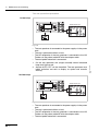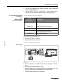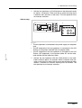
1
VIO 300 S V 1.0.x
V 1.1.x
V 1.2.x
VIO 200 S V 1.2.x
02.08
Service Manual
ERBE
SERVICE MANUAL
VIO 300 S
VIO 200 S
Service Manual Art.No. 80116-284
All rights to this manual, in particular rights of duplication, dissemination and translation, are reserved. No part of
this manual may be reproduced in any form (by photocopying, microfilming or other methods) or processed, duplicated or disseminated by the use of electronic systems without the written consent of ERBE Elektromedizin GmbH.
The information contained in this manual may be amended or supplemented without prior notice and represents
no obligation on the part of ERBE Elektromedizin GmbH.
Printed by ERBE Elektromedizin
Printed in Germany
Copyright © ERBE Elektromedizin GmbH, Tübingen 2008
TABLE OF CONTENTS
Table of Contents
Chapter
1
Title
Page
Safety information.......................................................................... 7
Classification of the safety information ........................................................7
Knowledge of the User Manual....................................................................7
Protection from the risk of electric shock .....................................................7
Electrostatically sensitive components ........................................................8
Liability and warranty ...................................................................................8
2
Modifications .................................................................................. 9
3
Unit description ............................................................................ 11
Unit variants ...............................................................................................11
Controls at the front ...................................................................................12
Art.-Nr.: 80116-284
02.08
Controls at the rear ....................................................................................13
4
Technical Data .............................................................................. 15
5
Setup and Service settings ......................................................... 17
General information ...................................................................................17
Overview of Setup settings ........................................................................17
Overview of Service settings .....................................................................18
Call up Setup and Service settings ............................................................20
Change settings .........................................................................................22
6
Remedying malfunctions............................................................. 23
Safety information ......................................................................................23
ERROR list ................................................................................................23
Abbreviations of Error displays ............................................................. 23
A/E-Errors ............................................................................................. 24
B-Errors ................................................................................................ 27
C-Errors ................................................................................................ 33
D-Errors ................................................................................................ 35
Err-Errors .............................................................................................. 36
F-Errors................................................................................................. 37
2,3,5,6-Errors........................................................................................ 38
4 (NE)-Errors ........................................................................................ 40
9-Errors................................................................................................. 41
5 / 70
TABLE OF CONTENTS
7
Maintenance and servicing.......................................................... 43
Who is allowed to perform servicing and maintenance work? .................. 43
What is a safety check? ............................................................................ 43
How often does a safety check have to be performed? ............................ 43
Art.-Nr.: 80116-284
02.08
Safety check – step by step ...................................................................... 44
Safety information................................................................................. 44
Testing and measuring equipment ....................................................... 45
User manual and visual inspections ..................................................... 46
Tests to be conducted in accordance with the national
specifications and regulations .............................................................. 46
DC resistance ....................................................................................... 47
Performance tests ................................................................................ 48
Footswitch activation ............................................................................ 50
Fingerswitch activation ......................................................................... 51
Automatic start mode............................................................................ 52
Automatic stop mode............................................................................ 53
Spark monitor ....................................................................................... 54
HF power output CUT........................................................................... 56
HF power output COAGULATE............................................................ 58
Performance test upgrades .................................................................. 61
Monitor circuits ..................................................................................... 63
6 / 70
1 • Safety information
CHAPTER 1
Safety information
Classification of the safety information
WARNING!
The WARNING! safety indication refers to a risk of personal injury.
CAUTION!
The CAUTION! safety indication refers to a risk of damage to property.
ATTENTION!
The ATTENTION! safety indication refers to a risk which can cause
equipment to become unserviceable.
IMPORTANT!
The IMPORTANT! designation indicates application information
and other particularly important information.
Knowledge of the User Manual
Art.-Nr.: 80116-284
02.08
The User Manual for this unit constitutes an integral part of this Service Manual. For performing servicing activities it is assumed that the
reader has knowledge of the User Manual, especially procedures for
installation, putting into operation, and handling.
Protection from the risk of electric shock
WARNING!
The supply voltage must match the voltage specified on the rating
plate. Connect the unit / the equipment cart to a properly installed
grounded outlet. Only use the ERBE power cord or an equivalent
power cord for this purpose. The power cord must bear the
national test symbol.
For safety reasons, multiple outlets and extension cords should
not be used. If their use is unavoidable, they also must be provided
with proper grounding.
WARNING!
Unplug the power cord from the outlet before exchanging parts of
the unit or cleaning it.
WARNING!
Do not plug a wet power cord into the unit or into an outlet.
WARNING!
Do not touch any unprotected wires or conductive surfaces while
the unit is opened and under voltage.
7 / 70
1 • Safety information
WARNING!
Blown line fuses may only be replaced by a competent technician.
Only replacement fuses of the rating specified on the unit's name
plate may be used. Before resuming operation the unit must be
subjected to a performance test by a competent technician.
Electrostatically sensitive components
CAUTION!
This unit contains electrostatically sensitive components. Work at
an anti-static workplace while repairing the unit. Wear a grounding
armband while working with electrostatically sensitive components. Hold the circuit boards by their non-conducting corners.
Use an anti-static container for transporting electrostatically sensitive components and the circuit boards.
Liability and warranty
ATTENTION!
Adjustments, tests, modifications, maintenance and repair work
may only be performed by ERBE or persons trained by ERBE. If
the work is not performed by trained persons, ERBE accepts no
liability and warranty rights become void.
ATTENTION!
8 / 70
Only use original ERBE spare parts. The manufacturer accepts no
liability and the warranty rights becomes void if original spare parts
are not used.
Art.-Nr.: 80116-284
02.08
It is recommended that the safety check also be performed by
ERBE or persons trained by ERBE.
2 • Modifications
CHAPTER 2
Modifications
As from VIO version 1.1.x
Hardware
Component affected
Description of the modification
IES 2 module
The IES 2 smoke evacuation system can be attached to the
VIO HF surgical unit and operated via said unit.
EIP 2 module
The EIP 2 irrigation pump can be attached to the VIO HF
surgical unit and operated via said unit.
Software
Art.-Nr.: 80116-284
02.08
Component affected
Service settings
Description of the modification
New Service settings:
IES parameter
EIP parameter
Test programs
New Test programs:
TP user interface
Set EEPROM default
9 / 70
2 • Modifications
As from VIO version 1.2.x
Hardware
Component affected
HF-Generator
Description of the modification
Development of a new HF generator module which will be
recognized and supported by VIO S devices from software
version 1.2.x onward.
Software
Component affected
Setup settings
Description of the modification
DRY CUT ° can be switched on and off independently of
SWIFT COAG ° (depending on the unit variant).
Art.-Nr.: 80116-284
02.08
SWIFT COAG ° can be switched on and off independently of
DRY CUT ° (depending on the unit variant).
10 / 70
3 • Unit description
CHAPTER 3
Unit description
Unit variants
How do the unit variants differ from one another?
There are VIO S units in different unit variants. Each unit variant has
modes assigned permanently to it.
In the VIO 300 S the unit variant 1 (= basic variant) contains all modes
approved for this unit. These modes are described in the User Manual of the unit. All other units contain less modes than the basic variant. A list of all unit variants for the VIO 300 S can be requested from
ERBE Tübingen.
Currently only unit variant 1 is available in the VIO 200 S. The modes
of this variant are described in the User Manual of the unit.
How do I determine the unit
variant?
When the VIO S is switched on, the following information about the
unit software appears on the start screen:
Art.-Nr.: 80116-284
02.08
• Software status (e.g. 1.2.x)
• Upgrades (e.g. EndoCut I)
• Unit variant (e.g. Variation 2)
The VIO 200 S is an exception. Since at the time of printing only unit
variant 1 is available, no statement about the unit variant is made on
the start screen.
Which service work does the
unit variant affect?
The unit variant has an effect on the adjustment and some tests of the
safety check.
11 / 70
3 • Unit description
Controls at the front
IMPORTANT!
This chapter contains an overview of the controls of the unit(s).
The relevant User Manual for the unit(s), knowledge of which is
assumed for servicing work, provides detailed information about
how to use the unit(s).
11
ERBE
300 S
17
10
7
FORCED
COAG
+
Effect
8
9
6
+
CUT
12
+
13
Effect
+
COAG
max. Watts
16
max. Watts
F
14
15
1
Power Switch
2
+/– buttons
3
CUT LED
4 –9
10
11 – 14
12 / 70
Selection buttons
COAG LED
Focus buttons
15
Pilot lamps for neutral electrodes
16
Pilot lamps for footswitches
17
Pilot lamp for AUTO START
Art.-Nr.: 80116-284
02.08
Fig. 3-1
3 • Unit description
Controls at the rear
IMPORTANT!
This unit comes with different power supply modules – plug-in or
screw-in.
Art.-Nr.: 80116-284
02.08
VIO S with screw-in power supply module
Fig. 3-2
1
Footswitch sockets
2
ECB socket (ERBE Communication Bus)
3
Potential equalization terminal
4
Power supply module with fuses
13 / 70
3 • Unit description
VIO S with plug-in power supply module
14 / 70
1
Footswitch sockets
2
ECB socket (ERBE Communication Bus)
3
Potential equalization terminal
4
Power supply module with fuses
Art.-Nr.: 80116-284
02.08
Fig. 3-3
4 • Technical Data
CHAPTER 4
Technical Data
Power connection
Rated supply voltage
100 V – 120 V ± 10% / 220 V – 240 V ± 10%
Rated supply frequency
50 / 60 Hz
Line current
8A/4A
Power input in standby mode
40 watts
Power input with max. HF output
500 watts / 920 VA
Terminal for grounding (potential equalization)
yes
Power fuses
T8A/T4A
Art.-Nr.: 80116-284
02.08
Operating mode
Intermittent operation
ON time 25% (e.g. activated for 10 sec. / deactivated for 30 sec.)
Dimensions and weight
Width x height x depth
410 x 165 x 380 mm
Weight
8.8 kg
Ambient conditions for transport and storage of unit
Temperature
-40 °C to + 70 °C
Relative humidity
10% – 95%
Ambient conditions for operation of unit
Temperature
+10 °C to + 40 °C
Relative humidity
15% – 80%, noncondensing
15 / 70
4 • Technical Data
Acclimatizing
If the unit has been stored or transported at temperatures below +10 °C or above +40 °C, the unit will
require approx. 3 hours to acclimatize at room temperature.
Standards
II b
Protection class as per EN 60 601-1
I
Type as per EN 60 601-1
CF
Art.-Nr.: 80116-284
02.08
Classification according to EC Directive 93/42/
EEC
16 / 70
5 • Setup and Service settings
CHAPTER 5
Setup and Service settings
General information
This unit features two levels for changing settings:
• Setup level
• Service level
Overview of Setup settings
Art.-Nr.: 80116-284
02.08
Accessible to users and service personnel.
Setting
Available from
Description
Contrast
V 1.0.x
Setting display contrast.
System volume
V 1.0.x
Setting the volume of activation tones.
The activation tones must be easy to hear!
Key volume
V 1.0.x
Setting key volume.
AUTO START
V 1.0.x
Input of start delay for the AUTO START function.
Brightness LED
V 1.0.x
Setting the brightness of the LEDs.
Brightness Display
V 1.0.x
Setting display brightness.
17 / 70
5 • Setup and Service settings
Overview of Service settings
Only accessible to service personnel.
Setting
Available from
Description
Date
V 1.0.x
Self-explanatory.
Time
V 1.0.x
Self-explanatory.
Neutral electrode
V 1.0.x
Single surface
Dual surface
Either way
Dynamic
Time limit
V 1.0.x
Setting the time after which activation terminates automatically.
Automatic time
V 1.0.x
Setting the time for which an input box is shown on the display.
Error list
V 1.0.x
Saves all the errors that are detected and reported.
Version list
V 1.0.x
Indicates the software versions of all the connected components.
"Safe config." option 1
APC parameter
V 1.0.x
Setting the following parameters:
APC supply: self-explanatory.
APC Auto Purge: the instrument is automatically purged
with gas when it is plugged into the APC receptacle or if the
instrument is plugged into the APC receptacle already it is
automatically purged with gas when the unit starts up.
APC purge duration: selection of period for which the
instrument is purged with gas automatically. 1 to 10 s.
APC purge flow: selection of purge flow (in %) at which the
instrument is purged with gas automatically. Purge flow
relates to the default COAG Flow setting stored in the
instrument.
Language
V 1.0.x
Self-explanatory.
Start screen
V 1.0.x
Start screen type selection.
18 / 70
Art.-Nr.: 80116-284
02.08
Factory setting up to V 1.1.x: Either way
Factory setting as from V 1.2.x: Dynamic
5 • Setup and Service settings
Setting
DRY ° / SWIFT ° 2
Available from
V 1.0.x to V 1.1.x
Description
ON:
Modes DRY CUT ° / SWIFT COAG ° are used.
OFF:
Modes DRY CUT / SWIFT COAG are used.
DRY CUT ° /
SWIFT COAG ° 2
V 1.2.x
DRY CUT ° activated:
Mode DRY CUT ° is used.
DRY CUT ° deactivated:
Mode DRY CUT is used.
SWIFT COAG ° activated:
Mode SWIFT COAG ° is used.
Art.-Nr.: 80116-284
02.08
SWIFT COAG ° deactivated:
Mode SWIFT COAG is used.
AUTO START
V 1.0.x
Setting to specify whether AUTO START is permitted as an
activation mode.
Test programs
V 1.0.x
Selection of hardware test programs.
IES parameter
V 1.1.x
Setting the parameters for operation of the IES 2 smoke
evacuation system.
EIP parameter
V 1.1.x
Setting the parameters for operation of the EIP 2 irrigation
pump.
1. "Safe config." saves the unit receptacle configuration recognized by the system. The receptacle configuration must be saved by the service
technician after every software update and after every unit upgrade and conversion. For this purpose compare the receptacle configurations
indicated on the "Version list" with the physical configurations on the unit. If the two agree, save the receptacle configurations with "Safe
config.".
2. depending on the unit variant.
19 / 70
5 • Setup and Service settings
Call up Setup and Service settings
Call up Setup level
1. Call up "CUT-COAG" box and select menu item "Prog.Setup".
2. Select menu item "Setup". The unit switches to the Setup level.
For the settings that can be changed there see table page 17.
Art.-Nr.: 80116-284
02.08
Call up Service level
1. Call up "CUT-COAG" box and select menu item "Prog.Setup".
2. Select menu item "Service". The unit switches to the "Password
input" box.
20 / 70
5 • Setup and Service settings
3. In the menu item "Case" select upper case.
Art.-Nr.: 80116-284
02.08
4. Enter password VIOS. When doing so use the Up and Down keys
to set the initial letter.
5. Confirm the correct letter with the selection button.
6. Repeat steps 3 to 5 letter by letter.
21 / 70
5 • Setup and Service settings
7. Confirm password with menu item "SERVICE". The unit switches
to the Service level. For the settings that can be changed there
see table page 18.
IMPORTANT!
Once the keyword has been entered and provided the unit remains
switched on, the Service level can be called up direct, i.e. without
having to repeat keyword entry. By switching off the unit the Service level is protected by the keyword against unauthorized access
again.
Change settings
A setting change does not have to be confirmed. The unit executes
it immediately. After restarting the unit the changed setting
remains intact.
1. Mark the setting that is to be changed using the selection buttons.
2. Press the selection button next to the mark. A new box opens. In
that box the setting can be changed with the nearest selection
button.
22 / 70
Art.-Nr.: 80116-284
02.08
IMPORTANT!
6 • Remedying malfunctions
CHAPTER 6
Remedying malfunctions
Safety information
ATTENTION!
Adjustments, technical tests, modifications, maintenance and
repair work may only be performed by ERBE or persons trained by
ERBE. If the work is not performed by trained persons, ERBE
accepts no liability and warranty rights become void.
ERROR list
Art.-Nr.: 80116-284
02.08
Abbreviations of Error displays
A:
APC 2-Errors
B:
Control panel-Errors
C:
CPU + Sensors-Errors
D:
IES 2-Errors (=Smoke evacuation system)
E:
VEM 2-Errors
Err:
Error display on the seven-segment displays of the VIO
F:
Footswitch-Errors
2,3,5,6:
IIF-Errors (=Instrument Interface) of corresponding
receptacle slot
4 (NE):
Nessy2-Errors
9:
EIP 2-Errors (=ERBE Irrigation Pump)
23 / 70
6 • Remedying malfunctions
Status of ERROR list: 02.08
A/E-Errors
Recognizing module: A = APC 2, E = Extension module VEM 2
Recognizing
module
Error
code
A
01
Restart the unit. If the error
occurs again, notify ERBE
Service.
A/E
02 – 04
Restart the unit. If the error
occurs again, notify ERBE
Service.
A/E
05
Button error receptacle 1.
Check the keyboard.
A/E
06
Button error receptacle 2.
Check the keyboard.
A
07 – 09
Restart the unit. If the error
occurs again, notify ERBE
Service.
A
0A
Restart the unit. If the error
occurs again, notify ERBE
Service.
A/E
0B
Information in test mode
(adjustment).
A/E
0C – 0D
Restart the unit. If the error
occurs again, notify ERBE
Service.
A
10
Underpressure at selected
gas input.
Check the gas supply (tank,
pressure regulator). If the
error persists, notify ERBE
Service.
A
11
Overpressure at selected
gas input.
Check the gas supply (tank,
pressure regulator). If the
error persists, notify ERBE
Service.
A
12
Caloric and differential
pressure sensor do not
agree (wrong gas).
Check the gas supply (type
of gas). If the error persists,
notify ERBE Service.
A
13
24 / 70
Description
Action
Restart the unit. If the error
occurs again, notify ERBE
Service.
Art.-Nr.: 80116-284
02.08
Additional information
6 • Remedying malfunctions
Art.-Nr.: 80116-284
02.08
Recognizing module: A = APC 2, E = Extension module VEM 2
Recognizing
module
Error
code
A/E
21 – 23
Restart the unit. If the error
occurs again, notify ERBE
Service.
A
30
Restart the unit. If the error
occurs again, notify ERBE
Service.
A/E
38
Type detection of
receptacle 1 fails to agree
with the stored value.
Check and save the receptacle configuration in the
"Version List" test program.
If the error occurs again,
notify ERBE Service.
A/E
39
Type detection of
receptacle 2 fails to agree
with the stored value.
Check and save the receptacle configuration in the
"Version List" test program.
If the error occurs again,
notify ERBE Service.
A
40
Flow specification not
attained.
Check the accessories. If
the error persists, notify
ERBE Service.
A
41
Flow specification
exceeded.
Restart the unit. If the error
occurs again, notify ERBE
Service.
A/E
7D + 7E
A/E
7F
Operating system error.
Information, no fault condition.
A/E
80
Internal state incorrect.
Information, no fault condition.
A/E
81 – 83
Protocol violation CAN.
Restart the unit. If the error
occurs again, notify ERBE
Service.
A/E
85
Invalid resistance instrument number.
Check the accessories. If
the error persists, notify
ERBE Service.
A
86
Gas underdose, e.g. hose
blocked.
Check the accessories. If
the error persists, notify
ERBE Service.
Additional information
Description
Action
Restart the unit. If the error
occurs again, notify ERBE
Service.
25 / 70
6 • Remedying malfunctions
Recognizing module: A = APC 2, E = Extension module VEM 2
Recognizing
module
Error
code
A
Additional information
Description
Action
90
Low pressure at cylinder 1.
Check the gas supply (tank,
pressure regulator). If the
error persists, notify ERBE
Service.
A
91
Low pressure at cylinder 2.
Check the gas supply (tank,
pressure regulator). If the
error persists, notify ERBE
Service.
A
A0
Art.-Nr.: 80116-284
02.08
Restart the unit. If the error
occurs again, notify ERBE
Service.
26 / 70
6 • Remedying malfunctions
B-Errors
Art.-Nr.: 80116-284
02.08
Recognizing module: B = Control panel
Recognizing
module
Error
code
B
02 + 03
B
05 (as
to 1.1.x)
NESSY message; NE is
not correctly applied:
Occurs if measurement of
the NE contact resistance
is outside the valid range
on activation.
Check the NE accessories
and NE setting in setup.
B
0B (as
from
1.2.x)
NESSY message; NE is
not correctly applied:
Occurs if measurement of
the NE contact resistance
is outside the valid range
on activation.
Check the NE accessories
and NE setting in setup.
B
10
Please terminate activation: Occurs if activation
has been automatically terminated (e.g. by AutoStop)
and the activation signal
remains (longer than 5 s)
(e.g. footswitch).
Check the accessories. If
the error persists, notify
ERBE Service.
B
14
B
17
Double activation:
Occurs if two activation signals (e.g. both pedals of a
footswitch) are present
simultaneously (within
100 ms).
Check the accessories. If
the error persists, notify
ERBE Service.
B
19
PowerFail:
Occurs if a PowerFail signal is received but the PowerFail does not actually
happen within 2 s.
Check the supply input
voltage.
Additional information
Description
Action
Restart the unit. If the error
occurs again, notify ERBE
Service.
Restart the unit. If the error
occurs again, notify ERBE
Service.
27 / 70
6 • Remedying malfunctions
Recognizing
module
Error
code
B
Additional information
Description
Action
1C
The maximum ON time
has been exceeded:
Occurs if activation lasts
longer than the ON time
selected in Setup.
Check the accessories. If
the error persists, notify
ERBE Service.
B
1E
Keyboard error:
Occurs if a button pressed
is recognized during initialization.
Check the keyboard.
B
1F
NESSY symmetry monitoring:
Occurs if an error is signaled by the Nessy symmetry monitoring during
activation.
Check the NE accessories.
B
2A – 2C
Restart the unit. If the error
occurs again, notify ERBE
Service.
B
50 – 59
Restart the unit. If the error
occurs again, notify ERBE
Service.
B
5A
Error in the version check:
Occurs if the VEM module
attempts to log with an
invalid version.
Remove the module concerned from the unit and
notify ERBE Service.
B
5B
Error in the version check:
Occurs if the IES module
attempts to log with an
invalid version.
Remove the module concerned from the unit and
notify ERBE Service.
B
5C
Error in the version check:
Occurs if the EIP module
attempts to log with an
invalid version.
Remove the module concerned from the unit and
notify ERBE Service.
B
5D
Error in the version check:
Occurs if a dual-pedal footswitch attempts to log with
an invalid version.
Remove the module concerned from the unit and
notify ERBE Service.
B
5E
Error in the version check:
Occurs if a single-pedal
footswitch attempts to log
with an invalid version.
Remove the module concerned from the unit and
notify ERBE Service.
28 / 70
Art.-Nr.: 80116-284
02.08
Recognizing module: B = Control panel
6 • Remedying malfunctions
Art.-Nr.: 80116-284
02.08
Recognizing module: B = Control panel
Recognizing
module
Error
code
B
Additional information
Description
Action
5F
Error in the version check:
Occurs if a ReMode footswitch attempts to log with
an invalid version.
Remove the module concerned from the unit and
notify ERBE Service.
B
60
Error in the version check:
Occurs if an IES footswitch
attempts to log with an
invalid version.
Remove the module concerned from the unit and
notify ERBE Service.
B
81
B
84
Footswitch was recognized by the system:
Occurs if a footswitch is
connected.
Information, no fault condition.
B
85
Footswitch was disconnected from the system:
Occurs if a footswitch is
disconnected from the system.
Information, no fault condition.
B
87
Restart the unit. If the error
occurs again, notify ERBE
Service.
B
8B
Restart the unit. If the error
occurs again, notify ERBE
Service.
B
8D
B
8E + 8F
Restart the unit. If the error
occurs again, notify ERBE
Service.
B
90
Restart the unit. If the error
occurs again, notify ERBE
Service.
Restart the unit. If the error
occurs again, notify ERBE
Service.
No status message from
APC module:
Occurs if an APC module
is disconnected from the
system.
Check connectors. Check
APC.
29 / 70
6 • Remedying malfunctions
Recognizing module: B = Control panel
Recognizing
module
Error
code
B
Additional information
Action
91
No status message from
IES module:
Occurs if the IES module is
disconnected from the system.
Check connectors. Check
IES 2.
B
95
New instrument recognized
by system:
Occurs if an instrument
with instrument recognition is connected.
Information, no fault condition.
B
9F
Instrument has been disconnected from the system: Occurs if an
instrument with instrument
recognition is disconnected
from the system.
Information, no fault condition.
B
A0
No other mode can be set
for this instrument:
Occurs if the user wants to
assign a different mode to
an instrument with a fixed
mode.
Information, no fault condition.
B
A3
Footswitch not assigned:
Occurs if a footswitch
which has not been
assigned to an output
receptacle is pressed.
Assign the footswitch activation.
B
A4
Two footswitches are connected: Occurs if two footswitches of the same type
are connected.
Remove the duplicate footswitch from the unit.
B
AA
No valid mode is assigned:
Occurs if an output channel is activated without a
mode being assigned to it.
Information, no fault condition.
B
AB
Activation is only possible
with a valid instrument:
Occurs if a MF receptacle
is activated at which no
instrument is recognized.
Check the accessories. If
the error persists, notify
ERBE Service.
30 / 70
Art.-Nr.: 80116-284
02.08
Description
6 • Remedying malfunctions
Recognizing module: B = Control panel
Recognizing
module
Error
code
B
Additional information
Action
B0
NESSY symmetry warning:
Occurs if the Nessy symmetry monitoring signals a
value between 20 % and
50 %.
Check the NE accessories.
B
B1
NESSY current density
warning:
Occurs if the Nessy current
density monitoring signals
a value above the limit
curve.
Check the NE accessories.
B
C4
Purge function not
assigned:
Occurs if the purge button
on the APC is pressed and
no APC receptacle was
selected.
Information, no fault condition.
B
C5
Purge function not
assigned:
Occurs if the Purge button
on the APC is pressed an
no instrument is connected.
Information, no fault condition.
B
D2
No status message from
VEM module:
Occurs if the VEM module
is disconnected from the
system.
Information, no fault condition.
B
D3
No status message from
EIP module:
Occurs if the EIP module is
disconnected from the system.
Information, no fault condition.
B
D4 – D6
B
DA
Occurs if a module
responds that is not supported by the system.
Remove the module concerned from the unit and
notify ERBE Service.
B
DB
Occurs if a button that is
not selectable is pressed
(after a timeout).
Remove the module concerned from the unit and
notify ERBE Service.
Art.-Nr.: 80116-284
02.08
Description
Restart the unit. If the error
occurs again, notify ERBE
Service.
31 / 70
6 • Remedying malfunctions
Recognizing module: B = Control panel
Recognizing
module
Error
code
B
DC
B
EA
Module was recognized:
Occurs if a module is recognized.
Information, no fault condition.
B
EB
Receptacle was recognized:
Occurs if a receptacle is
recognized.
Check and save the receptacle configuration in the
"Version List" test program.
If the error occurs again,
notify ERBE Service.
Description
Action
Restart the unit. If the error
occurs again, notify ERBE
Service.
Art.-Nr.: 80116-284
02.08
Additional information
32 / 70
6 • Remedying malfunctions
C-Errors
Art.-Nr.: 80116-284
02.08
Recognizing module: C = CPU + Sensors
Recognizing
module
Error
code
C
01
Restart the unit. If the error
occurs again, notify ERBE
Service.
C
04 – 06
Restart the unit. If the error
occurs again, notify ERBE
Service.
C
0D
Restart the unit. If the error
occurs again, notify ERBE
Service.
C
21
Restart the unit. If the error
occurs again, notify ERBE
Service.
C
26
Restart the unit. If the error
occurs again, notify ERBE
Service.
C
30 – 38
Restart the unit. If the error
occurs again, notify ERBE
Service.
C
41 – 48
Restart the unit. If the error
occurs again, notify ERBE
Service.
C
51 – 58
Restart the unit. If the error
occurs again, notify ERBE
Service.
C
5A + 5B
Restart the unit. If the error
occurs again, notify ERBE
Service.
C
61 – 64
Restart the unit. If the error
occurs again, notify ERBE
Service.
C
70 – 72
Restart the unit. If the error
occurs again, notify ERBE
Service.
C
75
Restart the unit. If the error
occurs again, notify ERBE
Service.
Additional information
Description
Action
33 / 70
6 • Remedying malfunctions
Recognizing module: C = CPU + Sensors
Recognizing
module
Error
code
C
7D – 7F
Restart the unit. If the error
occurs again, notify ERBE
Service.
C
81 – 84
Restart the unit. If the error
occurs again, notify ERBE
Service.
C
91 + 92
Restart the unit. If the error
occurs again, notify ERBE
Service.
C
A0 + A1
Restart the unit. If the error
occurs again, notify ERBE
Service.
C
C0
Restart the unit. If the error
occurs again, notify ERBE
Service.
C
F0
Restart the unit. If the error
occurs again, notify ERBE
Service.
34 / 70
Description
Action
Art.-Nr.: 80116-284
02.08
Additional information
6 • Remedying malfunctions
D-Errors
Art.-Nr.: 80116-284
02.08
Recognizing module: D = Smoke evacuation system IES 2
Recognizing
module
Error
code
D
80
D
81
Excess temperature
(> 60 °C).
Overtemperature IES2: Let
the unit cool down.
D
82
Insufficient temperature
(< 0 °C).
Undertemperature IES2:
Leave unit on for several
minutes without operating.
D
83
Restart the unit. If the error
occurs again, notify ERBE
Service.
D
86
Restart the unit. If the error
occurs again, notify ERBE
Service.
D
87
Obstruction.
Remove the suction tube
from the tissue.
D
88
The filter is missing or
obstructed.
Insert or replace the filter.
Additional information
Description
Action
Restart the unit. If the error
occurs again, notify ERBE
Service.
35 / 70
6 • Remedying malfunctions
Err-Errors
Err = Error display on the seven-segment displays
Display
Description
Action
Restart the unit. If the error occurs again,
notify ERBE Service.
ErrtAS
Restart the unit. If the error occurs again,
notify ERBE Service.
Art.-Nr.: 80116-284
02.08
ErrdIS
36 / 70
6 • Remedying malfunctions
F-Errors
Recognizing module: F = Footswitch
Error
code
F
01
Additional information
Description
Action
CRC error: Occurs if an
error is detected during
CRC monitoring of the footswitch at start-up (e.g. bit
failure in the Flash memory
or error when downloading
software).
Replace the ECBS footswitch.
Art.-Nr.: 80116-284
02.08
Recognizing
module
37 / 70
6 • Remedying malfunctions
2,3,5,6-Errors
Recognizing module: 2,3,5,6 = IIF (Instrument Interface) of corresponding receptacle slot
Error
code
Additional information
Description
Action
2,3,5,6
(Buchse)
01 – 07
2,3,5,6
(Buchse)
08
2,3,5,6
(Buchse)
09
2,3,5,6
(Buchse)
0A
2,3,5,6
(Buchse)
0C – 0E
2,3,5,6
(Buchse)
0F
2,3,5,6
(Buchse)
70 – 72
2,3,5,6
(Buchse)
81
Short circuit instrument recognition R: The resistor
value determined for the
instrument recognition corresponds to a short circuit.
Check the accessories. If
the error persists, notify
ERBE Service.
2,3,5,6
(Buchse)
82
Short circuit activation recognition R_NEU: The resistor value determined for the
activation recognition corresponds to a short circuit.
Check the accessories. If
the error persists, notify
ERBE Service.
38 / 70
Restart the unit. If the error
occurs again, notify ERBE
Service.
Overcurrent activation recognition:
The measurement current
for analysis of the activation
recognition is too high.
Check the accessories. If
the error persists, notify
ERBE Service.
Restart the unit. If the error
occurs again, notify ERBE
Service.
Overcurrent instrument recognition:
The measurement current
for analysis of the instrument recognition is too
high.
Check the accessories. If
the error persists, notify
ERBE Service.
Restart the unit. If the error
occurs again, notify ERBE
Service.
U Coag error: +12 V voltage during Coag activation
too low.
Check the accessories. If
the error persists, notify
ERBE Service.
Restart the unit. If the error
occurs again, notify ERBE
Service.
Art.-Nr.: 80116-284
02.08
Recognizing
module
6 • Remedying malfunctions
Recognizing module: 2,3,5,6 = IIF (Instrument Interface) of corresponding receptacle slot
Art.-Nr.: 80116-284
02.08
Recognizing
module
Error
code
Additional information
Description
Action
2,3,5,6
(Buchse)
83
No-load activation recognition R_NEU: The resistor
value determined for the
activation recognition corresponds to no-load.
Check the accessories. If
the error persists, notify
ERBE Service.
2,3,5,6
(Buchse)
84
Instrument recognition Rwindow violated: The resistor value determined for the
instrument recognition cannot be reliably assigned to
a setpoint.
Check the accessories. If
the error persists, notify
ERBE Service.
2,3,5,6
(Buchse)
85
Short circuit activation recognition R_ALT: The resistor value determined for the
activation recognition corresponds to a short circuit.
Check the accessories. If
the error persists, notify
ERBE Service.
2,3,5,6
(Buchse)
86
Activation error: Activation
not consistent with instrument type.
Check the accessories. If
the error persists, notify
ERBE Service.
2,3,5,6
(Buchse)
87 – 89
Restart the unit. If the error
occurs again, notify ERBE
Service.
2,3,5,6
(Buchse)
8A – 8F
Restart the unit. If the error
occurs again, notify ERBE
Service.
2,3,5,6
(Buchse)
90
Restart the unit. If the error
occurs again, notify ERBE
Service.
39 / 70
6 • Remedying malfunctions
4 (NE)-Errors
Recognizing module: 4 (NE) = Nessy2
Recognizing
module
Error
code
4 (NE)
01 – 08
Restart the unit. If the error
occurs again, notify ERBE
Service.
4 (NE)
0C – 0E
Restart the unit. If the error
occurs again, notify ERBE
Service.
4 (NE)
10 + 11
Restart the unit. If the error
occurs again, notify ERBE
Service.
Description
Action
Art.-Nr.: 80116-284
02.08
Additional information
40 / 70
6 • Remedying malfunctions
9-Errors
Art.-Nr.: 80116-284
02.08
Recognizing module: 9 = ERBE Irrigation Pump EIP 2
Recognizing
module
Error
code
Additional information
9
80
CRC Error.
9
82
Pump lid open at
ON.
Description
Action
Restart the unit. If the error
occurs again, notify ERBE
Service.
User error:
The pump lid of the EIP 2 is
not closed at the start of
activation or is opened during activation.
Close the pump lid before
activation or do not open it
during activation.
Unit error.
Restart the unit. If the error
occurs again, notify ERBE
Service.
User error:
Activation of the EIP 2 was
maintained for more than
20 seconds. Maximum activation time for the EIP 2 is
20 seconds.
End the activation. It is then
possible to active the EIP 2
new. If the error occurs
again, check the accessories.
9
84
Time Out Error.
9
88
UeWS Error
Restart the unit. If the error
occurs again, notify ERBE
Service.
9
90
No current or no
load.
Restart the unit. If the error
occurs again, notify ERBE
Service.
9
A0
Current too high
at ON.
Restart the unit. If the error
occurs again, notify ERBE
Service.
9
C0
Motor control
faulty (voltage too
high at ON).
Restart the unit. If the error
occurs again, notify ERBE
Service.
41 / 70
Art.-Nr.: 80116-284
02.08
6 • Remedying malfunctions
42 / 70
7 • Maintenance and servicing
CHAPTER 7
Maintenance and servicing
Who is allowed to perform servicing and maintenance work?
ATTENTION!
Adjustments, tests, modifications, maintenance and repair work
may only be performed by ERBE or persons trained by ERBE. If
the work is not performed by trained persons, ERBE accepts no
liability and warranty rights become void.
It is recommended that the safety check also be performed by
ERBE or persons trained by ERBE.
What is a safety check?
Art.-Nr.: 80116-284
02.08
IMPORTANT!
The safety check is a preventive measure to examine whether the
device is safe and ready for operation. In order to perform the various tests the current specifications and regulations of the particular country and the instructions in this service manual must be
observed.
How often does a safety check have to be performed?
IMPORTANT!
ERBE recommends performing a safety check after every repair,
but at least once a year.
43 / 70
7 • Maintenance and servicing
Safety check – step by step
For simplification the device to be tested is referred to below as the
"test specimen".
Safety information
44 / 70
For safety reasons (personnel protection) the test specimen
should generally be operated by a suitable isolating transformer.
An exceptional case is the tests for grounded conductor resistance, ground leakage current, and patient leakage current, in
which the test specimen is supplied with current via the safety
tester.
ATTENTION!
In the event of a fault occurring in the test specimen or individual
components during the safety check the test steps taken so far no
longer apply. Remedy the defect and repeat the safety check from
the beginning.
ATTENTION!
The specifications made in this chapter for test programs / test
program settings allow the service technician to perform the safety
check. In addition, the test program mode provides a number of
diagnostic and inspection options for the service technician. They
are described in the repair manual. ERBE Elektromedizin
expressly states that the full functional range of the test program
mode may not be used without precise knowledge of the individual
test programs.
IMPORTANT!
It is assumed that the user knows how to operate the test specimen, the test equipment, the measuring equipment, and auxiliary
test equipment. The test instructions only apply in conjunction with
the relevant test steps.
IMPORTANT!
Test equipment, measuring equipment, and auxiliary test equipment (cables, test boxes, etc.) are listed separately at the beginning of each test unit. Where ERBE article numbers are specified,
only original ERBE test equipment, measuring equipment, and
auxiliary test equipment may be used.
IMPORTANT!
The test report for the safety check can be requested from ERBE
Technical Service Tübingen. For the address see address sheet
on last page.
Art.-Nr.: 80116-284
02.08
WARNING!
7 • Maintenance and servicing
Testing and measuring equipment
IMPORTANT!
Art.-Nr.: 80116-284
02.08
ERBE
Art. No.
The following list contains the testing and measuring equipment
recommended by ERBE for servicing. Where ERBE article numbers are specified, only original ERBE testing and measuring
equipment should be used.
Description
–
Safety tester (with insulation testing >500 V DC)
–
HF power meter
(recommended: Metron QA-ES)
–
Oscilloscope, 100 MHz or higher
(recommended: Tektronix TDS 1012)
–
High Voltage Differential Probe
(recommended: TESTTEC TT-SI 9010, Tektronix P5210 or Sapphire SI9010)
20188-100
Single-pedal footswitch
20189-100
Dual-pedal footswitch
20190-045
Electrode handle ICC/ACC
20192-127
Patient cable AE
20192-110
Patient cable AE, international
20196-045
Bipolar cable
20196-053
Bipolar cable, international
20100-034
Adapter cable bipolar
20194-070
Patient cable NE
20194-075
Patient cable NE, international
20100-033
Adapter cable NE
20100-035
Cable LF – leakage current
20100-038
Cable LF – leakage current, international
20100-101
VIO Testbox Symmetry/Resistance (NE asymmetry/critical resistance)
20100-102
VIO Testbox Auto Start/Auto Stop (bipolar start/stop)
20100-019
Testbox spark monitor, 230 V
45 / 70
7 • Maintenance and servicing
User manual and visual inspections
• Test specimen and accessories (where enclosed) undamaged
externally.
• User manual present.
• All labels on the test specimen (conformity declaration mark, rating plate, and all wording) present and readily legible.
Tests to be conducted in accordance with the
national specifications and regulations
Grounded conductor test
• Ground terminal to chassis.
• Ground terminal to potential equalization pin.
Ground leakage current
measurement
• Ground leakage current, normal condition (N.C.).
• Ground leakage current, single-fault condition (S.F.C.).
Patient leakage current
measurement
• Patient leakage current, normal condition (N.C.).
• Patient leakage current, single-fault condition (S.F.C.).
IMPORTANT! Close the output relay of the unit in the "TP relay" test
1. Call up service level (see page 20).
2. Select the "Test programs" setting and press the adjacent button
to call it up. The test specimen switches to the test program
mode.
3. Select the "TP relay" test program and press the adjacent button
to call it up.
4. Close all relays in the test program via "All":
– ------ Relays closed
– --/-- Relays open
5. Perform the measurement.
6. Switch the test specimen off.
46 / 70
Art.-Nr.: 80116-284
02.08
program for testing the patient leakage current. On the test specimen:
7 • Maintenance and servicing
DC resistance
Testing and measuring equipment
ERBE
Art. No.
20192-127
Description
Patient cable AE
or
20192-110
Patient cable AE, international
20190-045
Electrode handle ICC/ACC
20194-070
Patient cable NE
or
20194-075
Patient cable NE, international
20100-033
Adapter cable NE
–
Safety tester (with insulation testing
>500 V DC)
Art.-Nr.: 80116-284
02.08
Test setup
WARNING!
Across the measuring lines there is the DC voltage of 500 V! In
order to avoid injuries, only switch on the test specimen and safety
tester when all the electrical connections have been made.
ERBE
+
+
+
+
Fig. 7-1
• The test specimen is connected to the power supply via the power
cord.
• The NE receptacle of the test specimen is connected to the safety
tester via the patient cable with NE with the adapter cord.
• The AE receptacle of the test specimen is connected to the safety
tester via the patient cable with AE and electrode handle with the
laboratory cable.
47 / 70
7 • Maintenance and servicing
Test procedure
1. Start safety tester in the "Insulation resistance" function The
measured value displayed should be >200 MOhm.
2. Start test specimen and select the test progam "TP relay".
3. In the test program "TP relay" use "All" to switch through all the
output relays on the test specimen. When doing so the measured value displayed on the safety tester must drop significantly
from >200 MOhm.
4. Determine insulation resistance using the safety tester. The
measured value must be >2 MOhm.
5. Document the measured value.
Performance tests
Testing and measuring equipment
ERBE
Art. No.
Description
20189-100
Dual-pedal footswitch
20194-070
Patient cable NE
20194-075
Patient cable NE, international
20100-033
Adapter cable NE
Test setup
• The test specimen is connected to the power supply via the power
cord.
• The dual-pedal footswitch is connected.
• The NE patient cable with the shorted adapter cable is connected
to the NE receptacle on the test specimen.
Test procedure
48 / 70
Power switch
1. Check power switch for smooth operation. The power switch
must be easy to operate and must neither stick nor scrape.
2. Press power switch. The power switch must snap into the "ON"
position and the test specimen must perform a system start.
Start routine /
acknowledgement tone
1. The test specimen must perform the system start without error
message(s).
2. The test specimen must emit an acoustic signal (acknowledgement tone) during the self-test.
Art.-Nr.: 80116-284
02.08
or
7 • Maintenance and servicing
Pushbuttons / acknowledgement tone when pressed
Software download
1. Check all the pushbuttons (focus buttons, selection buttons,
+/– buttons) on the test specimen to make sure they are working
properly. Press each button at least twice. When pressing the
buttons there must be an acoustic signal every time
(= acknowledgement tone).
1. Document whether a software update was performed.
Neutral electrode setting
1. Call up service level (see page 20).
2. Then call up the neutral electrode setting and document the
existing setting.
Date and time
1. Remain in the Service level.
2. Then call up the date and time settings one after the other, check
the existing settings, and correct them if required.
Display / LEDs
Display:
1. Check the backlighting of the display to make sure it is operating
properly. If backlighting is faulty, no image will be visible.
Art.-Nr.: 80116-284
02.08
LEDs:
1. Upon system start all the LEDs and seven-segment displays
must light up briefly with equal brightness. In the case of the neutral electrode receptacle red and green must light up briefly one
after the other.
Activation tones
1. Press CUT pedal on the dual-pedal footswitch at least twice.
When pressing the pedal there must be an acoustic signal every
time (= acknowledgement tone).
2. Press COAG pedal on the dual-pedal footswitch at least twice.
When pressing the pedal there must be an acoustic signal every
time (= acknowledgement tone).
49 / 70
7 • Maintenance and servicing
Footswitch activation
Testing and measuring equipment
ERBE
Art. No.
Description
20188-100
Single-pedal footswitch
20189-100
Dual-pedal footswitch
20194-070
Patient cable NE
or
20194-075
Patient cable NE, international
20100-033
Adapter cable NE
• The test specimen is connected to the power supply via the power
cord.
• On the test specimen the basic program is selected.
• The single-pedal footswitch is connected.
• The dual-pedal footswitch is connected.
• The NE patient cable with the shorted adapter cable is connected
to the NE receptacle on the test specimen.
Test procedure
Single-pedal footswitch
activation COAG
1. Assign the single-pedal footswitch to any receptacle.
2. Press COAG pedal on the single-pedal footswitch. On the test
specimen COAG must be activated.
Dual-pedal footswitch
activation CUT / COAG
1. Assign the dual-pedal footswitch to any receptacle.
2. Press CUT pedal on the dual-pedal footswitch. On the test specimen CUT must be activated.
3. Press COAG pedal on the dual-pedal footswitch. On the test
specimen COAG must be activated.
50 / 70
Art.-Nr.: 80116-284
02.08
Test setup
7 • Maintenance and servicing
Fingerswitch activation
Testing and measuring equipment
ERBE
Art. No.
20192-127
Description
Patient cable AE
or
20192-110
Patient cable AE, international
20190-045
Electrode handle ICC/ACC
20194-070
Patient cable NE
or
20194-075
Patient cable NE, international
20100-033
Adapter cable NE
Test setup
Art.-Nr.: 80116-284
02.08
• The test specimen is connected to the power supply via the power
cord.
• On the test specimen the basic program is selected.
• The NE patient cable with the shorted adapter cable is connected
to the NE receptacle on the test specimen.
Test procedure
20190-045
Activation CUT / COAG
1. Connect the electrode handle with the AE patient cable to the 1st
Monopolar receptacle on the test specimen.
2. Press CUT button on the electrode handle. On the test specimen
CUT must be activated.
3. Press COAG button on the electrode handle. On the test specimen COAG must be activated.
4. Connect the electrode handle with the AE patient cable to the
2nd Monopolar receptacle (if present) on the test specimen.
5. Repeat test steps 2 and 3.
51 / 70
7 • Maintenance and servicing
Automatic start mode
Testing and measuring equipment
ERBE
Art. No.
Description
20196-045
Bipolar cable
or
20196-053
Bipolar cable, international
20100-034
Adapter cable bipolar
20100-102
VIO Testbox Auto Start/Auto Stop (bipolar
start/stop)
Test setup
ERBE
+
+
+
BP1
T2
1
2
X
X
X
X
BP2
Testbox 20100-102
Fig. 7-2
• The test specimen is connected to the power supply via the power
cord.
• The Bipolar receptacle of the test specimen is connected to the
VIO Testbox via the bipolar cable with the adapter cable.
Test procedure
1st test step
52 / 70
1. In the Setup of the test specimen establish the set start delay for
the AUTO START setting. Make a note of the value.
2. Set test specimen to:
BIPOLAR SOFT, Effect 1, 50 W
AUTO START
3. On the VIO Testbox press button T1. The test specimen must
start activation after the set start delay.
4. Press button T2. The test specimen must terminate activation.
Art.-Nr.: 80116-284
02.08
T1
+
7 • Maintenance and servicing
2nd test step
1. Set test specimen to:
BIPOLAR SOFT, Effect 8, 50 W
AUTO START
2. On the VIO Testbox press button T1. The test specimen must
start activation after the set start delay.
3. Press button T2. The test specimen must terminate activation.
Automatic stop mode
Testing and measuring equipment
ERBE
Art. No.
Description
20196-045
Bipolar cable
Art.-Nr.: 80116-284
02.08
or
20196-053
Bipolar cable, international
20100-034
Adapter cable bipolar
20100-102
VIO Testbox Auto Start/Auto Stop (bipolar
start/stop)
20188-100
Single-pedal footswitch
Test setup
ERBE
+
+
1
+
X
T3
+
BP3
3
4
X
X
BP4
Testbox 20100-102
Fig. 7-3
• The test specimen is connected to the power supply via the power
cord.
• The Bipolar receptacle of the test specimen is connected to the
VIO Testbox via the bipolar cable with the adapter cable.
• The single-pedal footswitch is connected.
53 / 70
7 • Maintenance and servicing
Test procedure
1. Set test specimen to:
BIPOLAR SOFT with AutoStop, Effect 4, 50 watts
2. On the VIO Testbox hold down button T3.
3. Activate BIPOLAR SOFT with the footswitch, keeping the pedal
pressed.
4. Hold down button T3 for approx. 5 s, then let go. Within another
9 s at the latest the test specimen must terminate activation and
emit two brief signal tones.
Spark monitor
Testing and measuring equipment
ERBE
Art. No.
20192-127
Description
Patient cable AE
20192-110
Patient cable AE, international
20190-045
Electrode handle ICC/ACC
20194-070
Patient cable NE
Art.-Nr.: 80116-284
02.08
or
or
20194-075
Patient cable NE, international
20100-033
Adapter cable NE
20100-019
Testbox spark monitor, 230 V
Test setup
Testbox 20100-019
Power
+
ERBE
AE
+
+
+
+
NE
Fig. 7-4
54 / 70
S1 DC 70 V
-
7 • Maintenance and servicing
• The test specimen is connected to the power supply via the power
cord.
• The test specimen is connected to the testbox.
Test procedure
Call up Test program mode
1. Call up service level (see page 20).
2. Select the "Test programs" setting and press the adjacent button
to call it up. The test specimen switches to the test program
mode.
3. Select the "TP generator" test program and press the adjacent
button to call it up.
Art.-Nr.: 80116-284
02.08
259
4. Select the receptacle on which to measure in the test program
under "Output receptacle" (select here: 2 = receptacle slot,
MONOPOLAR = arrangement with monopolar receptacle).
Measurement
1. On the Testbox press button S1.
2. In the test program read off the measured value for "Spark". The
tolerance range is 245 to 285 ERBE.
55 / 70
7 • Maintenance and servicing
HF power output CUT
Testing and measuring equipment
ERBE
Art. No.
20192-127
Description
Patient cable AE
or
20192-110
Patient cable AE, international
20190-045
Electrode handle ICC/ACC
20194-070
Patient cable NE
or
20194-075
Patient cable NE, international
20100-033
Adapter cable NE
20196-045
Bipolar cable
or
Bipolar cable, international
20100-034
Adapter cable bipolar
–
20189-100
AUTO CUT
DRY CUT
Art.-Nr.: 80116-284
02.08
20196-053
HF power meter
Dual-pedal footswitch
Test setup
ERBE
AE
+
+
+
+
NE
HF power meter
Fig. 7-5
• The test specimen is connected to the power supply via the power
cord.
• The levels of power are determined with the HF power meter. The
measuring cables are plugged into the HF power meter direct.
56 / 70
7 • Maintenance and servicing
Test procedure VIO 200 S
1. Set test specimen to:
AUTO CUT, Effect 8, 200 watts
2. Set HF power meter to:
RL = 500 ohms
3. Activate test specimen via CUT button on the electrode handle.
4. Determine and document measured value. The tolerance range
is 160 to 240 watts.
Test procedure VIO 300 S
Art.-Nr.: 80116-284
02.08
1. Set test specimen to:
AUTO CUT, Effect 8, 300 watts
2. Set HF power meter to:
RL = 500 ohms
3. Activate test specimen via CUT button on the electrode handle.
4. Determine and document measured value. The tolerance range
is 240 to 360 watts.
1. Set test specimen to:
DRY CUT, Effect 8, 200 watts
2. Set HF power meter to:
RL = 500 ohms
3. Activate test specimen via CUT button on the electrode handle.
4. Determine and document measured value. The tolerance range
is 160 to 240 watts.
BIPOLAR CUT
(depending on the
unit variant)
Test setup
ERBE
+
+
+
+
Bipolar
HF power meter
Fig. 7-6
• The test specimen is connected to the power supply via the power
cord.
• The levels of power are determined with the HF power meter. The
measuring cables are plugged into the HF power meter direct.
• The dual-pedal footswitch is connected.
57 / 70
7 • Maintenance and servicing
Test procedure
1. Set test specimen to:
BIPOLAR CUT, Effect 8, 100 watts
2. Set HF power meter to:
RL = 500 ohms
3. Activate test specimen via CUT pedal on the footswitch.
4. Determine and document measured value. The tolerance range
is 80 to 120 watts.
HF power output COAGULATE
Testing and measuring equipment
ERBE
Art. No.
20192-127
Description
Patient cable AE
20192-110
Patient cable AE, international
20190-045
Electrode handle ICC/ACC
20194-070
Patient cable NE
or
20194-075
Patient cable NE, international
20100-033
Adapter cable NE
20196-045
Bipolar cable
or
20196-053
Bipolar cable, international
20100-034
Adapter cable bipolar
–
20189-100
58 / 70
HF power meter
Dual-pedal footswitch
Art.-Nr.: 80116-284
02.08
or
7 • Maintenance and servicing
BIPOLAR SOFT COAG
Test setup
ERBE
+
+
+
+
Bipolar
HF power meter
Fig. 7-7
• The test specimen is connected to the power supply via the power
cord.
• The levels of power are determined with the HF power meter. The
measuring cables are plugged into the HF power meter direct.
• The dual-pedal footswitch is connected.
Art.-Nr.: 80116-284
02.08
Test procedure
1. Set test specimen to:
BIPOLAR SOFT, Effect 8, 120 watts
2. Set HF power meter to:
RL = 75 ohms
3. Activate test specimen via COAG pedal on the footswitch.
4. Determine and document measured value. The tolerance range
is 96 to 144 watts.
59 / 70
7 • Maintenance and servicing
SOFT COAG
FORCED COAG
SPRAY COAG (depending on
the unit variant)
Test setup
ERBE
AE
+
+
+
+
NE
HF power meter
Fig. 7-8
• The test specimen is connected to the power supply via the power
cord.
• The levels of power are determined with the HF power meter. The
measuring cables are plugged into the HF power meter direct.
1. Set test specimen to:
SOFT COAG, Effect 8, 120 watts
2. Set HF power meter to:
RL = 50 ohms
3. Activate test specimen via COAG button on the electrode handle.
4. Determine and document measured value. The tolerance range
is 96 to 144 watts.
1. Set test specimen to:
FORCED COAG, Effect 4, 120 watts
2. Set HF power meter to:
RL = 500 ohms
3. Activate test specimen via COAG button on the electrode handle.
4. Determine and document measured value. The tolerance range
is 96 to 144 watts.
Test procedure VIO 300 S
1. Set test specimen to:
SOFT COAG, Effect 8, 200 watts
2. Set HF power meter to:
RL = 50 ohms
3. Activate test specimen via COAG button on the electrode handle.
4. Determine and document measured value. The tolerance range
is 160 to 240 watts.
60 / 70
Art.-Nr.: 80116-284
02.08
Test procedure VIO 200 S
7 • Maintenance and servicing
1. Set test specimen to:
FORCED COAG, Effect 4, 120 watts
2. Set HF power meter to:
RL = 500 ohms
3. Activate test specimen via COAG button on the electrode handle.
4. Determine and document measured value. The tolerance range
is 96 to 144 watts.
1. Set test specimen to:
SPRAY COAG, Effect 2, 120 watts
2. Set HF power meter to:
RL = 500 ohms
3. Activate test specimen via COAG button on the electrode handle.
4. Determine and document measured value. The tolerance range
is 96 to 144 watts.
Performance test upgrades
Testing and measuring equipment
ERBE
Art. No.
Art.-Nr.: 80116-284
02.08
20192-127
Description
Patient cable AE
or
20192-110
Patient cable AE, international
20190-045
Electrode handle ICC/ACC
20194-070
Patient cable NE
or
20194-075
Patient cable NE, international
20100-033
Adapter cable NE
–
HF power meter
–
Oscilloscope
–
Probe 100:1
61 / 70
7 • Maintenance and servicing
ENDO CUT I and Q
Test setup
Oscilloscope
High Voltage
Differential probe
ERBE
AE
+
+
+
+
NE
HF power meter
• The test setup is designed as shown in the illustration above.
• The test specimen is connected to the power supply via the power
cord.
• The levels of power are determined with the HF power meter. The
measuring cables are plugged into the HF power meter direct.
Test procedure
1. Set test specimen to:
EndoCut I, Effect 1, Cutting duration 1, Cutting interval 1
2. Set HF power meter to:
RL = 1000 ohms
3. Connect the probe of an oscilloscope to AE and NE.
4. Set oscilloscope to:
200 V / Div, 20 ms
5. Activate test specimen via the CUT button on the electrode handle.
6. Determine the duration of the cutting pulse. The tolerance range
is 90 to 110 ms.
62 / 70
Art.-Nr.: 80116-284
02.08
Fig. 7-9
7 • Maintenance and servicing
1. Set test specimen to:
EndoCut Q, Effect 1, Cutting duration 1, Cutting interval 2
2. Set HF power meter to:
RL = 1000 ohms
3. Connect the probe of an oscilloscope to AE and NE.
4. Set oscilloscope to:
200 V/Div, 100 ms
5. Activate test specimen via the CUT button on the electrode handle.
6. Determine the duration of the cutting pulse. The tolerance range
is 320 to 380 ms.
Monitor circuits
NE monitoring of critical
resistance
for
single surfaced
neutral electrodes
Testing and measuring equipment
ERBE
Art. No.
20194-070
Description
Patient cable NE
Art.-Nr.: 80116-284
02.08
or
20194-075
Patient cable NE, international
20100-033
Adapter cable NE
20100-101
VIO Testbox Symmetry/Resistance (NE
asymmetry/critical resistance)
20189-100
Dual-pedal footswitch
Presets on the test specimen
• AUTO CUT, Effect 1, 10 watts.
• Neutral electrode "single surface".
63 / 70
7 • Maintenance and servicing
Test set-up and test procedure
1st test step
ERBE
Testbox 20100-101
+
+
+
+
3
4
6
7
8
9
10
11
1
2
5
12
Fig. 7-10
1. On the test specimen the (single surfaced) neutral electrode
lamp must light up red.
2. Activate AUTO CUT via the footswitch. The test specimen must
inhibit activation and emit or display an optical and acoustic
warning.
2nd test step
ERBE
Testbox 20100-101
+
+
+
+
3
4
6
7
8
9
10
11
1
2
5
12
Fig. 7-11
• The test specimen is connected to the power supply via the power
cord.
• The test is performed without a load.
• The NE receptacle of the test specimen is connected to the VIO
Testbox via the patient cable NE with the adapter cable.
• The dual-pedal footswitch is connected.
64 / 70
Art.-Nr.: 80116-284
02.08
• The test specimen is connected to the power supply via the power
cord.
• The test is performed without a load.
• The NE receptacle of the test specimen is connected to the VIO
Testbox via the patient cable NE with the adapter cable.
• The dual-pedal footswitch is connected.
7 • Maintenance and servicing
1. On the test specimen the (single surfaced) neutral electrode
lamp must light up green.
2. Activate AUTO CUT via the footswitch. It must be possible to
activate the test specimen without error or warning signals.
NE monitoring of critical
resistance
for
dual surfaced
neutral electrodes
Testing and measuring equipment
ERBE
Art. No.
20194-070
Description
Patient cable NE
or
20194-075
Patient cable NE, international
20100-033
Adapter cable NE
20100-101
VIO Testbox Symmetry/Resistance (NE
asymmetry/critical resistance)
20189-100
Dual-pedal footswitch
Presets on the test specimen
Art.-Nr.: 80116-284
02.08
• AUTO CUT, Effect 1, 10 watts.
• Neutral electrode "dual surface".
Test set-up and test procedure
1st test step
Testbox 20100-101
ERBE
3
4
6
7
8
9
10
11
1
+
+
+
+
2
5
12
Fig. 7-12
• The test specimen is connected to the power supply via the power
cord.
• The test is performed without a load.
• The NE receptacle of the test specimen is connected to the VIO
Testbox via the patient cable NE with the adapter cable.
• The dual-pedal footswitch is connected.
65 / 70
7 • Maintenance and servicing
1. On the test specimen the (dual surfaced) neutral electrode lamp
must light up red.
2. Activate AUTO CUT via the footswitch. The test specimen must
inhibit activation and emit or display an optical and acoustic
warning.
2nd test step
Testbox 20100-101
ERBE
3
4
6
7
8
9
10
11
1
+
+
+
+
2
5
12
• The test specimen is connected to the power supply via the power
cord.
• The test is performed without a load.
• The NE receptacle of the test specimen is connected to the VIO
Testbox via the patient cable NE with the adapter cable.
• The dual-pedal footswitch is connected.
1. On the test specimen the (dual surfaced) neutral electrode lamp
must light up green.
2. Activate AUTO CUT via the footswitch. It must be possible to
activate the test specimen without error or warning signals.
3rd test step
Testbox 20100-101
ERBE
3
4
6
7
8
9
10
11
1
Fig. 7-14
66 / 70
+
+
+
+
2
5
12
Art.-Nr.: 80116-284
02.08
Fig. 7-13
7 • Maintenance and servicing
• The test specimen is connected to the power supply via the power
cord.
• The test is performed without a load.
• The NE receptacle of the test specimen is connected to the VIO
Testbox via the patient cable NE with the adapter cable.
• The dual-pedal footswitch is connected.
1. On the test specimen the (dual surfaced) neutral electrode lamp
must light up red.
2. Activate AUTO CUT via the footswitch. The test specimen must
inhibit activation and emit or display an optical and acoustic
warning.
NE monitoring of asymmetry
Testing and measuring equipment
ERBE
Art. No.
20192-127
Description
Patient cable AE
Art.-Nr.: 80116-284
02.08
or
20192-110
Patient cable AE, international
20190-045
Electrode handle ICC/ACC
20194-070
Patient cable NE
or
20194-075
Patient cable NE, international
20100-033
Adapter cable NE
20100-101
VIO Testbox Symmetry/Resistance (NE
asymmetry/critical resistance)
Presets on the test specimen
• SOFT COAG, Effect 1, 10 watts.
• Neutral electrode "dual surface".
67 / 70
7 • Maintenance and servicing
Test set-up and test procedure
1st test step
AE
ERBE
NE
+
+
+
+
3
4
6
7
8
9
10
11
1
2
5
12
Testbox 20100-101
Fig. 7-15
1. Activate test specimen via COAG button on the electrode handle
for approx. 10 seconds. During the entire activation time there
must be no warning signal.
2nd test step
AE
ERBE
NE
+
+
+
+
3
4
6
7
8
9
10
11
1
2
5
12
Testbox 20100-101
Fig. 7-16
• The test specimen is connected to the power supply via the power
cord.
• The NE receptacle of the test specimen is connected to the VIO
Testbox via the patient cable NE with the adapter cable.
• The AE receptacle of the test specimen is connected to the VIO
Testbox (AE receptacle) via the patient cable AE and the electrode handle with the laboratory cable.
68 / 70
Art.-Nr.: 80116-284
02.08
• The test specimen is connected to the power supply via the power
cord.
• The NE receptacle of the test specimen is connected to the VIO
Testbox via the patient cable NE with the adapter cable.
• The AE receptacle of the test specimen is connected to the VIO
Testbox (AE receptacle) via the patient cable AE and the electrode handle with the laboratory cable.
7 • Maintenance and servicing
1. Activate test specimen via COAG button on the electrode handle
for approx. 10 seconds. There must be an optical warning signal
2 seconds after activation at the latest. The test specimen must
not interrupt activation.
3rd test step
AE
ERBE
NE
+
+
+
+
3
4
6
7
8
9
10
11
1
2
5
12
Testbox 20100-101
Art.-Nr.: 80116-284
02.08
Fig. 7-17
• The test specimen is connected to the power supply via the power
cord.
• The NE receptacle of the test specimen is connected to the VIO
Testbox via the patient cable NE with the adapter cable.
• The AE receptacle of the test specimen is connected to the VIO
Testbox (AE receptacle) via the patient cable AE and the electrode handle with the laboratory cable.
1. Activate the test specimen with the COAG button on the electrode handle for approx. 10 seconds. Within 2 seconds after activation at the latest an optical warning must be emitted and within
another 2 seconds an acoustic warning must be emitted. The
test specimen must interrupt activation.
69 / 70
Art.-Nr.: 80116-284
02.08
7 • Maintenance and servicing
70 / 70