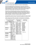
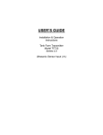
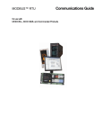
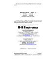
1
PAGE 1 OF 7
Q: How Can I Check My "4-Wire" RS-485 Port or Converter To Verify Operation?
A: When you're using a RS-485 converter that can be set up for 2-wire or 4-wire RS-485
operation, the RS-485 Receiver must be enabled (Echo On or RS-422 RX Enable) and the
Transmitter set to RS-485 Transmit mode. If the port or converter is the only Master talking to all
the Slaves, the Transmitter can be set to Enabled as in RS-422 mode, since the Transmit lines to
all the Slave Receivers don't need to be shared.
To test the Transmitter outputs and Receiver inputs, the Transmit signals are connected to the
Receive inputs. Bridge (connect) the TD(A) line to the RD(A) line, and the TD(B) line to the
RD(B) line (similar to 2-wire mode). Refer to Connection figures for loopback connections.
Refer to the Table for a list of models and jumper or switch settings. Some converter models
require Echo On or Receive Enable to be set by unsoldering a part or cutting a trace.
Serial Card Models With RS-485
(All have Rx Jumper)
RX Jumper must be set to 422 mode
ISA BUS
3PXCC1A
JP1C - port A
3PXCC2A
JP1C - port A
JP2C - port B
3PXCC4A
JP8 RX - port A
JP10 RX - port B
JP14 RX - port C
JP12 RX - port D
3PXOCC1A
JP3 RX
3PCOCC2A
JP1B RX - port A
JP2B RX - port B
3PXSD4A
JP3 RX - port A
JP4 RX - port B
JP7 RX - port C
JP8 RX - port D
PCI BUS
3PCIOSD1A
JP4 RX
3PCIOSD2A
JP4 RX - port A
JP6 RX - port B
3PCISD1A
JP1B (RX)
3PCISD2A
JP1B(RX)- port A
JP4B(RX)- port B
3PCISD4A
JP3BRX - port A
JP4B RX - port B
JP6B RX - port C
JP7B RX - port D
RS-485 Models With
Receive/Echo
Jumpers or Switch
485BAT3 - sw1B Off
485CON - install no
jumper pins#18 & 21
485COR - install no
jumper pins#18 & 21
485CSP2 - Echo on
485DRC - sw2 Off
485DRJ - sw4 Off
485HSPR - JP2 Off
485LDRC - sw2 Off
485OI9TB - JP1B On
485OIC - JP1 Off
485OICR - JP1 Off
485OISPR - JP2 Off
422OPINB - JP4 422
485OT9L - sw5 Off
485OTLED - sw5 Off
485TBLED - Echo On
RS-485 Models
Solder Echo
485COSN - remove R7
485COSR - remove R7
485LPCOR - cut trace
as shown on Fig 2 on
Data Sheet.
485PTBR - remove R9
Windows 95/98/SE/ME/2000 or NT 4.0: Use ComTest from our Website to check serial ports
assigned Com1 or higher under Windows. It can access Com ports 1-8, including USB serial
devices. ComTest will let open two different ports to check data from one to another or set DTR
high to power a port powered device and raise RTS to transmit and lower it to receive with RTS
controlled Converters or ports. ComTest Features are listed starting on page 6 of this FAQ.
MS-DOS: Use Simpterm from our Website to check motherboard or ISA based serial ports under
DOS. Do not use SimpTerm with Windows. The procedure is similar, but operating details are
different.
4-WIRE RS-485 TESTING
LOOPBACK CHECKS
PAGE 2 OF 7
Download & Install The Program
1. Before starting, make a Directory Folder (such as Test) on your hard drive to use when
downloading the program.
2. Go to the B&B Electronics Mfg. Co. Website. http://www.bb-elec.com
3. Select Support
4. View the right sidebar for Most Popular Downloads, Software
5. Select ComTest
6. Download into the directory (Test) you previously made.
7. Quit your web browser.
8. Open the directory (Test) you downloaded to.
9. Double-click com_test.exe
10. After file extraction is done, close the DOS window.
11. Double-click Setup within the Test folder.
12. Click Next, then Click Next.
13. Select destination directory. (default is C:\Program Files\B&B Electronics)
14. Click Next.
15. Click Finish button after “Installation Complete” message.
Note: If operating under Windows, a Com port number must be assigned by Windows, and it
must not be used by a serial mouse or open by another application.
MAKE DATA CONNECTIONS
Refer to the connection figures for Serial Card connectors or RS-485 Converters with Echo. Set
the Echo On or Receiver to RS-422 mode (4-wire 485 mode).
When the connections use DB9, DB25 or RJ11 connectors, it is usually easiest to wire a
matching connector or cable according to the pinouts. Refer to connection figures.
Some models can be looped back with switches as below:
485DRJ - sw1 - set on, sw2 - set on, sw4 - set off
485DRC or 485LDRC -sw3 - set on, sw4 - set on, sw2 - off (on is up and away from PCB)
485OT9L or 485OTLED - sw6 - on (2W), sw7 - on (2W), sw5 - off (on is toward outside/case)
4-WIRE RS-485 TESTING
LOOPBACK CHECKS
PAGE 3 OF 7
Note: DB9 & DB25 pin numbers are molded into the connector. To locate pin #1 on the male
connector hold the connector horizontally with the row with the most pins on top, the upper
leftmost pin is #1. On a female connector, the upper rightmost is #1.
4-WIRE RS-485 TESTING
LOOPBACK CHECKS
PAGE 4 OF 7
CONVERTER CONNECTIONS
Continued Next Page
PAGE 5 OF 7
USING COMTEST TO CHECK OPERATION
1. Make the Test Connections for Loopback and the required setting to Enable RX or Echo.
You should already have the Echo On or RX Enabled (422 mode) for 4-wire operation.
2.
Start ComTest from your Programs menu under B&B Electronics.
3. Select the Com port number you want to check. ComTest will only show Windows based
Com ports that are not in use. If another program is using the port, it will not be available.
Please close down any other programs that may be accessing the port. If another program is
using the same IRQ number that port is using, you will not be able to use both ports at once
unless both devices are PCI or USB based.
4. Accept the default baud rate, data bits, parity, stop bits.
5. If you are checking a RTS Controlled Converter or port: Select Options, then RTS (check
marked) to set the RTS indicator red. If using a Port Powered Converter requiring DTR Hi for
power, make sure the DTR indicator is red, DTR (check marked).
6. Type some characters in the upper window. The same characters should appear in the lower
window. Note that the enter key value will be shown in brackets as <0D>
If data is shown in the lower window when typed in the upper, the Converter or port is working.
Actual signal levels can be checked with a oscilloscope. With no termination, the levels must
exceed 200 mV at the receiver, 4 to 4.5 Volts difference between the TD(A) and TD(B) lines is
typical when Transmitting.. Due to Receiver Biasing (refer to the RS-422/RS-485 Application
Note in our Technical Library), the normal DC voltage between RD(A) and RD(B) is about 4 volts
(without 120 ohms termination or any devices connected), RD(B) is positive relative to RD(A) or
signal ground/common. With a dual trace scope in DC coupling mode, with one channel on
TD(A), and the other channel on TD(B), the two lines can be seen as opposite levels, when A is
high, B is low and vice versa. The receive lines should have similar voltages input.
Note:
1. RTS Control units require RTS hardware control software to operate properly. RTS control
timing can be critical for half duplex RS-485 control, and can be erratic under windows.
2. SD Control units require a matching baud rate setting if preset for 9600 baud. Resistors
and/or capacitor values may need to be changed. In 4-wire mode, the SD timing needs to be
altered for slower baud rates, but not usually for faster baud rates. If transmit is set for RS422 mode (single master 4-wire RS-485), the baud rate makes no difference since the
transmitter is always active.
3. Many Common problems are caused by wiring custom cables for the RS-232 side, especially
DB9 to DB25 and not understanding DTE/DCE devices. Usually Rx and Tx are wrong. Refer
to our web site Support, Technical Library for DTE/DCE Illustrations.
ComTest features listed on next page.
4-WIRE RS-485 TESTING
LOOPBACK CHECKS
PAGE 6 OF 7
B&B Electronics ComTest – A Serial Test Program For Port & Converter Testing With Windows
-
A Test Program for Simple Checks of Serial Ports, Serial Converters, Serial DAQ Devices.
Works with USB Serial Converters & ISA or PCI Serial Cards
-
Serial Port Access under Windows 95/98 and NT 4.0 – Com1-Com8 or above.
-
Dual Windows show typed transmit characters in separate window from received characters.
-
Transmit & Receive Activity Indicators
-
Unprintable Characters Shown in Hex – 2 Digits Within Left & Right Angle Brackets.
-
Visual Indication of Handshaking Lines – DTR DSR DCD and RTS CTS. (Red = Hi)
-
Option for Setting DTR or RTS lines high or low for port powered devices or RTS Control.
-
Option for Repeat Mode – last character or Function Character Sequence is repeated until
set off.
-
Option for Defining Strings to Output Using F1-F12 Keypress – Useful for DAQ Checkout
-
Option for Sending Unprintable Characters – Alt + 3 digit keycode, then release Alt.
-
Configuration Settings:
-
Baud Rates 150, 300, 600, 1200, 2400, 9600, 19.2, 28.4, 57.6, 115.2K (9600 default)
-
Parity: None, Odd, Even, Mark, Space (None is default)
-
Data Bits: 5, 6, 7, 8 (8 default)
-
Stop Bits: 1, 1.5, 2 (1 default)
Start ComTest
1. Connect the device to check to the serial port, or if performing a loopback test, make
connections.
2. Select Start, Programs, B&B Electronics, ComTest.
3. (If you get Win Port window showing shared modems, click Cancel)
4. ComTest Starts with a Select Port Window.
5. Select the Com port to access or test. (The drop down box shows available ports not in use).
6. Click Ok. Configure Port is shown.
7. Select the needed baud rate, parity, data bits, stop bits. (Defaults are common settings).
8. Type characters – they will appear in the upper window.
9. If performing a loopback test, observe the received characters in the lower window.
10. If sending commands to a serial DAQ device or Smart Switch, enter the control strings and
observe the device response or characters returned in the lower window.
4-WIRE RS-485 TESTING
LOOPBACK CHECKS
PAGE 7 OF 7
To Send Non-printable Characters Using Com Test
You can send non-printable control characters in a control string by pressing the Alt key and while
holding it down, enter the 3 digit character code using the separate numerical keypad on the
computer. For example, Esc=27. Press and hold Alt, then press 0 2 7 then release Alt.
For example: The Command for the 232SDA12 digital output is !0SO and bits. Hold Alt and
enter 0 0 1 or 0 0 2 or 0 0 4 to set each bit high. Enter 0 1 6 or 0 6 4 to set the 3 bits low.
ComTest cannot send the character value of zero.
Defining Strings To Send Using F1 to F12 Keys
1.
2.
3.
4.
Select Options, Strings, then under Key, select the F1 to F12 radio button.
Highlight and Delete the default String.
Enter the characters to be sent.
Select another key to define or OK to close the Window.
Press the F1-F12 key to send the characters.
Observe the response.
Setting RTS or DTR High or Low
Select Options on the menu bar.
Select RTS and/or DTR to set Hi. Select to unchecked mode to set Lo.
Exit
When testing is completed, close the program.
Removing Com Test
Close the program.
Select Settings, Control Panel, Add/Remove Programs, Select ComTest.
ComTest will be removed from the Program items.
4-WIRE RS-485 TESTING
LOOPBACK CHECKS