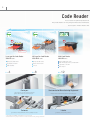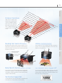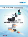
1
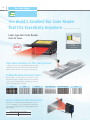
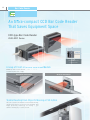
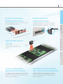
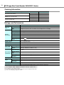
Code Reader/OCR
Tracing Products Group Catalog
High-accuracy, Multifunctional Readers
LOT. NO. S4153 2013
Ultra-compact, High-speed Readers
12 packs 2013.01.15
1 23456
7 89 10
2
Code Reader
You can select the optimum products from
We provide Readers for everything from Bar Codes and 2D Codes
The lineup also includes Readers that
Ultra Compact
Co
and Fast
NEW
NEW
World’s Smallest *1
Laser-type Bar Code Reader
CCD-type Bar Code Reader
Multi Code Reader
V500-R2 Series
V520-R221 Series
V400-R2 Series
High speed: 1,000 scans/s
High speed: 500 scans/s
Long distance: 270 mm
Distance: 40 ±12.5 mm
World’s Smallest
Low cost
Fastest reading in the class:
Reads moving objects at up to 500 m/min *2
Long distance: 125 mm
Ultra compact
P
4
P
8
P
12
Conveyors
Semiconductor Manufacturing Equipment
Ultra compact for possible mounting in rail gaps.
Stable reading of high-speed moving objects.
World’s smallest reader handles 300-mm wafer loading ports.
Cartoners
Labeler
Prevention of mixing of different cartons by reading bar codes.
Reading to check printing conditions.
*1.According to OMRON investigation in January 2013.
*2.Performance may depend on the code that is read and the printing conditions.
3
Bar Code Reader
and OCR Lineup
OMRON’s wide lineup of tracing products.
printed on paper or labels to DPM directly printed on workpieces.
can read expiration dates and other text.
High-accuracy
accurac
cy and Multifunctional
M
Multifunctio
onal
2D Code Reader for DPM
Multi Code Reader
2D Code Reader for DPM
Optical Character Recognition Sensor
Smart Camera
FQ-CR1 Series
FQ-CR2 Series
FQ2-CH Series
FQ2-S4 Series
HDR function to cut out
ambient light interference.
Polarizing filter to cut
specular reflections.
Reads direct part marking codes.
New OCR algorithm.
Code reader, OCR, and inspections.
Cuts halation from metallic surfaces.
Easy application with no
dictionary registration.
Lineup includes Integrated
Sensors and C-mounts.
Handles dot characters,
stamped characters, and more.
High resolution of
760,000 or 1,300,000 pixels.
High-power LED that is
effective for low contrast.
Verification with master data.
P
16
P
16
P
20
P
24
Optical Character Recognition Sensor
Multi Code Reader
Smart Camera
Case Packers
Automotive
Processing Machines
Lineup of models with many installation
distances from 38 to 970 mm.
Stable reading of low-contrast codes.
High-performance filters that cut
specular reflections from metallic or
glossy surfaces.
Cartoners
Multi-processing of everything needed for cartoners:
character verification, code reading, and inspections.
Reading 2D Codes
OK
Reading Bar Codes
OK
Reading DPM 2D Codes
Reading Bar Codes
Hot-melt Detection
Date Verification
OK
OK
OK
OK
4
Bar Co
Code Reader
*
The World’s Smallest Bar Code Reader
That Fits Essentially Anywhere
*According to OMRON investigation in January 2013.
Laser-type Bar Code Reader
V500-R2 Series
1/6
About
th the Size
of a Business Card
NEW
High-speed Reading at 1,000 Scans/Second
A high-speed motor and new algorithm gives surprising
performance for the size to achieve stable reading even in
high-speed takt machines of around 66,000 items/hour.
Enables Reading Imperfect Codes
Even though it is small, the V500-R2 with its new
algorithm is adept at reading even the most imperfect
codes. Raster scanning enables reading Bar Codes even
if they are partially dirty or missing.
Dirt
Wear
Blurring
Resists Ambient Light Interference
Operation is possible with ambient illumination of up to
80,000 lx (sunlight), so the Code Reader can stably read
even near Photoelectric Sensors with little influence from
ambient light.
Ambient Light Interference Guidelines
Florescent light
4,000 lx max.
Sunlight
80,000 lx max.
Shiny background
Inconsistent background
Dots
5
50
100
150
200
250
300
Bar Code Reader
0
Long Range Up to 270 mm
The wide reading distance from 60 to 270 mm lets you
60 to 270mm
handle variations in conveying and workpiece height
without changing the installation.
40°
2D Code Reader for DPM
Multi Code Reader
Reading Test Switch Provided
Just press the Scan button on the Reader to perform a read
test. The results are provided with the Read OK indicator
dicator
and buzzer. We achieved an operation that is simple
ple
enough for essentially anyone to increase mounting
ountin
ng
efficiency.
Scan Button
GS1-Databar (RSS) Supported
Reading is even possible for Bar Codes with narrow bars of
The data-rich GS1-Databar (RSS code) Bar Codes can also
0.15 mm.
be read.
Smart Camera
Minimum Readable Narrow Bar Width: 0.15 mm
0.15mm
Verification Supported
ed
Optical Character Recognition Sensor
Read OK Indicator
Verification with Immediately
Preceding Read Code
You can find out if a code is the same ass the one that was
just read. This lets you easily check for incorrect
items.
nco
orr
rrec
ectt it
item
ems.
s.
NG
OK
6
Laser-type Bar Code Reader V500-R2 Series
Ordering Information
Type
Model
Laser-type Bar Code Reader
V500-R2CF
OMRON PLC connecting cable
PC/AT Connecting cable
D-sub 9-pin, 0.8M
V509-W011
D-sub 9-pin, 5M
V509-W016
D-sub 9-pin, 0.8M
V509-W011D
D-sub 9-pin, 5M
V509-W016D
Ratings and Performance
Model
V500-R2CF
Direction of view
Applicable
codes
Reading
performance(*)
Interface
Front view
Bar code
WPC(JAN/EAN/UPC), Codabar(NW-7), ITF, Industrial 2 of 5(STF), Code39, Code93, Code128, GS1-128(EAN-128),
GS1-Databar(RSS-14), GS1-Databar Limited(RSS Limited), GS1-Databar Expanded(RSSExpanded)
Number of reading digits
No upper limit (depends on bar width and reading distance)
Minimum resolution
Bar code: 0.15 mm
Contrast (PCS)
0.45 or more (white reflectance 70 % or more)
Reading distance
60 to 270 mm (At narrow bar: 0.5 mm)
Reading angle
Within 40º (Including margins at left and right sides)
Skew angle (α)
±60º (However, exclude from 10º upper side to 8º lower side)
Pitch angle (β)
±30º
Tilt angle (γ)
±25º
Reading of bar codes
on curved surfaces (R)
R
Light source
Red laser diode (Wave length: 650 nm)
Light output
1.0m W or less (Correspond to JIS class 2)
Scan type
Raster scan
Number of scan
1000 scan/sec.
Communication
specification
RS-232C
OK/NG outputs
Function setting method
Functional
specifications
Power supply
specification
Environmental
specifications
External trigger (Transistor input), Trigger by command (RS-232C), Trigger a test reading by pressing the SCAN
button on the product
OK/NG signals
OK signal is turned on to indicate a successful read
NG signal is turned on to indicate a successful read of a non-registered label
Indication LED
OK LED (green) illuminates to indicate a successful read
Buzzer
Notifies a successful reading with a buzzer sound (Muting available)
Power voltage
4.5 to 5.5 VDC
Consumption current
During operation: 500 mA or less; during standby: 150 mA or less
Inrush current
2.0 A MAX
Ambient temperature range
At operation: 0 to + 45°C At storage: -20 to + 60°C
Ambient humidity range
At operation and storage: 20 to 85% RH (with no icing or condensation)
Ambient atmosphere
No corrosive gases
Ambient light
Fluorescent lamp: 4,000lx or less, Sunlight: 80,000lx or less
Degree of protection
Dimensions
NPN open collector output (cable work required)
Menu sheet reading method or host command method
Reading trigger
Vibration resistance
Weight
20mm (UPC 12 digit)
10 to 150 Hz, half amplitude 0.35 mm, 3 directions (X/Y/Z), 8 minutes each 10 times
IP54 (IEC60529)
Main unit only
Approximately 80 g
Including accessories
Approximately 190 g (including mounting bracket, insulation plate and screws)
Packaged weight
Approximately 270 g (including packing carton)
Main unit
Approximately 29(W) × 34.5(D) × 17(H)mm
Packing carton
Approximately 245(W) × 110(D) × 40(H)mm
Input/output connector
Round DIN connector
Code length
Approximately 1.5 m
Minimum bending radius of cord
Approximately 23 mm
Accessories
Operation manual, menu sheet, mounting bracket, insulation plate, M3 × 6 screw (two), M3 × 8 screws (one),
M5 × 10 screws (two)
Material, Color
Upper case
Magnesium diecast, black
Front panel
PC, black
Labels
PET
Reading window
PMMA, transparent
Cable
Polyvinyl chloride (PVC), black
Insulation plate
ABS, black
Mounting bracket
SUS304, silver
* Unless otherwise specified, use a JAN x1 , MRD 63% or higher (PCS = 0.9 or higher) bar code with a pitch angle
α = 0º, a skew angle β = 15º, a tilt angle γ = 0º, and a curvature R = ∞.
7
Reading range performance (typical example)
Bar Code Reader
Reading distance
0
100
200
300
400
(Unit: mm)
Explained with examples of
following conditions:
• Contrast: MRD 63 % (PCS = 0.9)
• Bar code: CODE39
• Installation condition:
Pitch angle α = 0°, skew angle β = 15°
Tilt angle γ = 0°, curvature R = ∞
40°
Pitch angle
Skew angle
Tilt angle
A
Curvature
B
C
Reading distance (*1)
A
0.15mm
70 to 140mm
B
0.25mm
60 to 200mm
C
0.5mm
60 to 270mm
D
1.0mm
70 to 330mm
*1. Distance from the end of the case.
D
Narrow bar width
Dimensions
2D Code Reader for DPM
Multi Code Reader
Narrow bar width
(Unit: mm)
Optical Character Recognition Sensor
37
20 dia.
Bar Code Reader
V500-R2CF
16
7
M3 Depth 3
7.3
7.3
6.25
(34.5)
Connector
Vinyl insulated round cord
3.8 dia. 10-core Black
Standard length 1.5 m
M3
Depth 3
18
2-M5
29
17
Smart Camera
13
Optical axis
Optical axis
7.19
6.65
4.45
15°
5°
9
R18
3
18
24
54
Safety Precautions for Laser Equipment
WARNING
Avoid eye exposure to direct or scattered radiation reflected by a mirror surface.
Laser Label Indications
This warning label is attached to the
Bar Code Reader.
Laser beam emitted from a laser has high power density and may become
Never remove this label or place
blind when the beam is directed into eyes.
objects in front of it.
Related Manuals
Man.No.
Model number
Manual
Z334
V500-R2
Laser-Type Bar Code Reader V500-R2 Series User's Manual
5.5
dia
.
10°
12.65
13
21.02
38
23
6.65
Mounting hole dimensions
8
Bar Co
Code Reader
An Ultra-compact CCD Bar Code Reader
That Saves Equipment Space
CCD-type Bar Code Reader
V520-R221 Series
Front-view Model
Half
Side-view Model
About
the Size
of a Business Card
Lineup of Front-view
e and Side-view
ew
Side view
wM
Models
OMRON provides both Front-view and
d Side-view
Sid i
Readers
R d
to handle any direction or angle.
Horizontal Installation
Vertical Installation
Stable Reading from Objects Moving at 50 m/min
This low-cost Bar Code Reader can read labelss moving
at high speed. There is no need to stop the labels.
bels. Still
image processing technology for moving ima
images
mages
achieves reading at 500 scans/second.
9
Bar Code Reader
Compact, Yet Provides a
Reading Width of 80 mm
Reading Possible for
0.125-mm Narrow Bars
Bar Code labels that are up to 80 mm wide can be read at
A reading resolution for up to 0.125-mm narrow bars has
the center reading distance (40 mm).
been achieved. Reading is possible even for information-
0.125mm
80mm
0
27.5
2D Code Reader for DPM
Multi Code Reader
dense Bar Code labels with large quantities of information.
40.0
52.5
Optical Character Recognition Sensor
Ample Reading Depth at
±12.5 mm
m was
was achieved
achi
ac
hiev
eved
e to make
A reading depth of ±12.5 mm
ssible even for verti
tical mo
move
veme
ment
n in th
the
e
stable reading possible
vertical
movement
workpiece.
Smart Camera
Function Settings with a
Menu Sheet and Commands
Safety Measures Such as Those for
Laser Light Sources Are Not Required
Easy setting of reading methods from a menu sheet is
The Bar Code Reader uses an LED light source so there is
accompanied by function settings with command commu-
no need to deal with laser safety standards. There is also
nications from a computer or other host. This is very
no motor or other moving parts, so troublesome mainte-
effective for process changeovers.
nance is not necessary.
10
CCD-type Bar Code Reader V520-R221 Series
Ordering Information
Type
CCD-type Bar Code Reader
OMRON PLC connecting cable
PC/AT Connecting cable
Model
Front-view
V520-R221FH
Side-view
V520-R221SH
D-sub 9-pin, 0.8M
V509-W011
D-sub 9-pin, 5M
V509-W016
D-sub 9-pin, 0.8M
V509-W011D
D-sub 9-pin, 5M
V509-W016D
Ratings and Performance
Item
Applicable
codes
Reading
performance
Model
V520-R221FH/R221SH
Bar code
JAN/EAN/UPC(A.E version), CODE 39, NW7, ITF, CODE 128(EAN128), CODE 93, STF(2 of 5 5bar)
Number of reading
digits
32 digits max. (However, ITF: even number of 4 to 32 digits, STF: 3 to 32 digits)
Resolution *6
0.125mm *1
Contrast (PCS)
0.3 min. (ground color reflectance of 85% min.)*2
Reading width*6
80mm
Reading distance *6
40 ± 12.5mm *3
Light source
RED LED
Number of scan
500 scan/sec.
Label moving
speed*6
50m/min(
angle)*4
Operation modes
(1) External trigger input (non-voltage contacts or transistor)
(2) Host trigger (RS-232C)
Interface
RS-232C
Function setting method
Menu sheet reading method or host command method
Power supply
specification
Power voltage
5 VDC ± 5% *5
Consumption
current
140mA typ. 200mA max. (distance of +5V)
Ambient
temperature range
0 to 40°C
Ambient humidity
Environmental range
specifications
Ambient light
Vibration
resistance
Degree of protection
Weight
30 to 85%RH (with no condensation)
6,000 lx max. (fluorescent light)
10 to 55Hz 20m/s2 X/Y/Z directions 1hour each
IP40 (IEC60529)
Main unit only
60g max.
Including
accessories
210g max. (with bracket, excluding cables)
Input/output connector
DIN 8pin
Code length
2m
*1. Minimum resolution: 0.125, Applicable range: At center at 60 mm with installation distance of 35 mm (0.15 mm for entire range)
*2. Specified at JAN 1.0x.Specified at an installation distance of 35 mm.
*3. Value for JAN 1.0x 13-digit JIS (X0501) standard label (PCS 0.9 min., reflectivity of 85% min.)
Use an installation distance around 35 mm for labels that require high-resolution reading.
*4. Value for JAN 1.0x 13-digit JIS (X0501) standard label (PCS 0.9 min., reflectivity of 85% min.)
*5. Specified at the edge of the I/O connector.
Do not exceed 3 m for the power supply and trigger line cables, including the Reader cables.
*6. Refer to the Reading Range Diagram for details.
11
Reading Ranges and Optical Axes (Typical Examples)
Bar Code Reader
V520-R221FH (Front-view)
V520-R221SH (Side-view)
40mm
30
40mm
20
30
20
Note:
0
20
30
20
40mm
30
40mm
03
27.5 35
52.5
30 40
03
27.5 35
52.5
Surface of mounting bracket
Dimensions
(Unit: mm)
Bar Code Reader
V520-R221FH
2D Code Reader for DPM
Multi Code Reader
: Measurement values at JAN 1.0x
(including label margins)
: Measurement range for labels with
0.15-mm narrow bar width.(including label margins)
: Measurement range for labels with 0.125-mm narrow
bar width.(including label margins)
Use an installation distance centered on 35 mm for labels that
require high-resolution reading, such as those with extremely
small narrow band widths.
0
24
Power/Read OK indicator
6.5
24.2
6
Mounting Bracket (Enclosed)
8.8
Optical axis
2-M2×6 (Enclosed)
80
57 35
72
50.5
Connector
43
4.5
8
20 dia.
Reading position
37
16
27.7
2.8
2
11.3
Bar Code
4.5
3.3
36
53
8
8.5
10°
8
Mounting Hole Dimensions
14.4
2-M4
4.2
Optical Character Recognition Sensor
16
Vinyl-insulated round cable,
5 dia. standard length: 2 m
36±0.2
37
Power/Read OK indicator
6.5
24.2
10
4.6
Mounting Bracket (Enclosed)
2-M2×6 (Enclosed)
24
Optical axis
16
Vinyl-insulated round cable,
5 dia. standard length: 2 m
39
80
57
72
50.5
Connector
43
4.5
8
20 dia.
2.8
9.5
37
16
2.5
Reading position
8
2
8.5
Bar Code
4.5
8
3.3
36
53
10°
61.4
Mounting Hole Dimensions
2-M4
36±0.2
14.4
27.7
Smart Camera
Bar Code Reader
V520-R221SH
12
Multi C
Code R
Reader
The Ultra-small Multi-code Reader
That Can Handle Speed
Multi Code Reader
V400-R2 Series
NEW
1/3
1
About
rd the Size
Business Card
of a Bu
Improves Machine Takt Time with the
Fastest Reading in the Class:
Reads Moving Objects at Up to 500 m/min*
It is not just the size that makes this Reader easy to build
into equipment. It enables stable reading of moving objects
on high-speed lines. Build it into equipment to read moving
objects, which is achieved with a new algorithm.
* Performance may depend on the code that is read and the printing conditions.
Stable Reading of Imperfect
perfect Codes
The V400-R2 with its new algorithm is adept
eptt even
ep
ev n the mostt im
impe
imperfect
perf
rfec
e t codes. Even
Even for codes
code
d s that were previously d
difficult
ifficult to read, you can
hie
ieve
ve tthe
he o
ptim
pt
imum
um settings
setting
gs to
o enable
enable reading.
change the exposure time and gain to achieve
optimum
Dirt
Wear
Blurring
Shiny background
Inconsistent background
Dots
Standard
Wear
Damage
Low contrast
Distortion
Dots
13
Bar Code Reader
Distance Variations
93
×5
9m
There are two models in the
lineup to let you select the field
48
×3
1m
of view or installation distance
m
that is best for the equipment
is not necessary to change the
65
m
m
m
5m
12
model.
90
100
110
120
130
80
70
2D Code Reader for DPM
Multi Code Reader
type. Both models are the same
size, so additional design work
m
60
50
40
30
20
Reading Test Switch Provided
Aiming
We achieved an operation that is simple enough for essen-
A guide light lets you easily find the ideal installation
tially anyone. Just press the Scan button on the Reader to
position. You can easily and quickly position the codes
perform a read test. The results are provided with the Read
with the aiming function.
Positioning Function
OK indicator and buzzer.
Smart Camera
Buzzer Sound Hole
Reading Window
Read OK Indicator
Scan Button
Body Resists Environments
nments
t to IP655
GS1-Databar (RSS) Support
G
GS1-D
Supported
IP65 protection is provided because that is generally the
The data-rich GS1-Databar (RSS code) Bar Codes can
level that is required to build devices into equipment.
also be read. This enables reliable applications in the
That enables reliable application in harsh environments
pharmaceutical industry, where GS1-Databar (RSS code)
subject to water and mist.
Bar Codes are becoming popular.
Verification Supported
You can verify if a code is the same as the one that was just
read. This lets you easily check for incorrect items.
Optical Character Recognition Sensor
10
0
14
Multi Code Reader V400-R2 Series
Ordering Information
Type
Model
Working distance 65mm
Multi Code Reader
OMRON PLC connecting cable
PC/AT Connecting cable
V400-R2CF65
Working distance 125mm
V400-R2CF125
D-sub 9-pin, 0.8M
V509-W011
D-sub 9-pin, 5M
V509-W016
D-sub 9-pin, 0.8M
V509-W011D
D-sub 9-pin, 5M
V509-W016D
Ratings and Performance
Model
V400-R2CF65
Direction of view
Applicable
codes
Reading
performance (*)
Interface
Bar code
WPC(JAN/EAN/UPC), Codabar(NW-7), ITF, Industrial 2 of 5, Code39,Code93, Code128,
GS1-128(EAN-128), GS1-Databar(RSS-14),GS1-Databar Limited(RSS Limited),
GS1-Databar Expanded (RSS Expanded), GS1-Databar Composite(RSS Composite)
2D code
QR code, DataMatrix(ECC200), MicroQR code, PDF417, MicroPDF417,AztecCode, MaxiCode, Codablock-F
Number of reading digits
No upper limit (depends on bar width and reading distance)
Light source
Two red LEDs (wave length: 617 nm)
Aiming light
One green LED (wave length: 528 nm)
Minimum resolution
Bar code: 0.076 mm
2D code: 0.169 mm
Image capture device
Monochrome CMOS
Effective number of pixels
754 × 480 pixels
Working distance (WD)
65mm
125mm
Field of view
Approximately 48 × 31(for WD = 65 mm)
Approximately 93 × 59(for WD = 125 mm)
Skew angle (α)
±50º
Pitch angle (β)
±50º
Tilt angle (γ)
±180º
Reading of bar codes
on curved surfaces (R)
R
Communication specification
RS-232C
OK/NG outputs
NPN open collector output (cable work required)
Function setting method
Functional
specifications
Power supply
specification
Environmental
specifications
Dimensions
20mm (UPC 12 line)
Menu sheet reading method or host command method
Reading trigger
OK/NG signals
OK signal is turned on to indicate a successful read
OK signal is turned on to indicate a successful read of registered label
NG signal is turned on to indicate a successful read of a non-registered label
Indication LED
OK LED (green) illuminates to indicate a successful read
Buzzer
Notifies a successful reading with a buzzer sound (Muting available)
Power voltage
4.5 to 5.5 VDC
Consumption current
During operation: 265 mA or less; during standby: 70 mA or less
Ambient temperature range
At operation: 0 to + 45ºC; At storage: -10 to + 60ºC
Ambient humidity range
At operation and storage: 20 to 85% RH (with no icing or condensation)
Ambient atmosphere
No corrosive gases
Ambient light
Fluorescent lamp: 10,000lx or less, Sunlight: 100,000lx or less
Vibration resistance
10 to 150 Hz, half amplitude 0.35 mm, 3 directions (X/Y/Z), 8 minutes each 10 times
IP54 (IEC60529)
Main unit only
Approximately 90 g
Including accessories
Approximately 200 g (including mounting bracket and screws)
Packaged weight
Approximately 280 g (including packing carton)
Main unit
Approximately 41(W) × 33(D) × 24(H) mm
Packing carton
Approximately 240(W) × 110(D) × 40(H) mm
Input/output connector
Round DIN connector
Code length
Approximately 1.5 m
Minimum bending radius of cord
Approximately 23 mm
Operation manual, menu sheet, mounting bracket, M2 × 6 screws (two), M5 ×10 screws (two)
Accessories
Material, Color
Bar code: 0.127 mm
2D code: 0.212 mm
External trigger (Transistor input)
Trigger by command (RS-232C)
Trigger a test reading by pressing the SCAN button on the product
Degree of protection
Weight
V400-R2CF125
Front view
Case
PC, PET, black
Reading window
PMMA, transparent
Cable
Polyvinyl chloride (PVC), black
Mounting bracket
SUS304, silver
* Unless otherwise specified, the reading performance is defined with angle α = 0º, β = +15º, γ = 0º, R = ∞; illuminance:100 to 2001x, reading rate: 90% or more.
•QR code is the registered trademark of DENSO WAVE.
15
Reading range performance (typical example)
2D code (typical example)
Code types
100
QR Code
50
Data Matrix
PDF417
0
50 65
100
125 150
200
250
300
Bar code (typical example)
Code types
50
(48, 31)
(93, 59)
Code39
Code128
UPC
Explained with examples of following conditions:
•Contrast: MRD 63% (PCS = 0.9)
•Installation condition:
Pitch angle α = 0°, skew angle β = 15°
Tilt angle γ = 0°, curvature R = ∞
•Reading rate: 90% or more in 10 tries
Pitch angle
Skew angle
Resolution Reading distance Field-of-view size at reading distance
0.127
85 to 125
63×47 to 92×59
0.254
65 to 205
48×31 to 152×96
0.508
60 to 295
44×28 to 218×138
0.2
75 to 185
55×35 to 137×87
0.33
50 to 220
37×23 to 163×103
V400-R2CF65
2D code (typical example)
Code types
QR Code
Data Matrix
Tilt angle
Curvature
PDF417
Resolution Reading distance Field-of-view size at reading distance
0.169
60 to 80
44×28 to 59×38
0.381
35 to 115
26×16 to 85×54
0.212
55 to 90
41×26 to 67×42
0.127
55 to 80
41×26 to 59×38
0.254
55 to 115
41×26 to 85×54
2D Code Reader for DPM
Multi Code Reader
100
(Horizontal field of view, Vertical field of view)
Resolution Reading distance Field-of-view size at reading distance
0.212
90 to 115
67×42 to 85×54
0.381
55 to 195
41×26 to 144×91
0.254
75 to 145
55×33 to 107×68
0.169
80 to 140
59×38 to 104×66
0.254
60 to 195
44×28 to 144×91
Bar Code Reader
V400-R2CF125
(Unit: mm)
Bar code (typical example)
Code types
Code128
UPC
Dimensions
(Unit: mm)
20 dia.
Multi Code Reader
V400-R2CF65/R2CF125
16
37
Smart Camera
2-M2 Depth 3 max
10.65
Optical axis
Vinyl insulated round cord 3.8 dia.
10-core Black
Standard length 1.5 m
24
18.4
41.1
35.1
Connector
2-M2
Depth 3 max
33
30°
22
R1
3
.6
2-R2
Optical axis
26.45
2.2 dia.
2-M5
.1
Man.No.
Model number
Manual
Z333
V400-R2
Multi Code Reader V400-R2 Series User's Manual
1
1.
R
2-
Related Manuals
13
15°
15°
R35
8.9
5.2 dia.
12
10.65
12
25
18
1.25
10.65
Optical axis
30°
47
1.25
Optical Character Recognition Sensor
Code39
Resolution Reading distance Field-of-view size at reading distance
0.076
60 to 65
44×28 to 48×31
0.127
55 to 85
41×26 to 63×40
0.254
50 to 115
37×23 to 85×54
0.18
45 to 100
33×21 to 74×47
0.33
45 to 120
33×21 to 89×56
Mounting hole dimensions
16
Multi Code Reader
Reade
FQ-CR1 series
2D Code Reader for DPM
FQ-CR2 series
Highly Advanced, Multi-functional Code Reader
That Can Handle Low-contrast and Glossy Surfaces
Multi
M
ulti Code
Co Reader
FQ-CR1 S
Series
erie
2D Code Reader for
Direct Part Marking codes
FQ-CR2 Series
FQ-CR1
FQ-CR2
High-power LEDs
The wider the field of view, the more difficult it is to maintain consistent lighting
within the field, causing errors in reading. The built-in LEDs of the FQ-CR Series
use a unique OMRON DR optical system for effective light usage to maintain
consistent lighting within the field of view at a brightness that is four times that of
Previous Lighting
High-power Lighting
Halation
Stable Detection for
Metal Surfaces Subject to
Gloss and Inconsistent
Lighting
Without Polarizing Filter
With Polarizing Filter
previous models.
HDR Function to Cut Out Ambient Light Interference
The HDR (high dynamic range) function minimizes the influence of changes in
lighting conditions and light reflection. This enables stable inspections even for
materials that are difficult to light evenly, such as metal parts or glossy films, or in
locations subject to external light interference.
Polarizing Filter to Cut Specular Reflections
A polarizing filter is included to cut specular reflection from glossy surfaces. This
enables stable code reading even for metallic or other glossy surfaces.
Connection of Up to 32 Readers
Up to 32 Code Readers can be controlled
from the Touch Finder setup console.
Expansion of required processes is
simple.
Connect up to 32 readers
17
Bar Code Reader
FQ-CR2
Removing Printing Irregularities or Noise
You can apply up to three of the four unique filters developed by
Combining Filtering
Erosion and dilation can be combined to
connect dots without changing the dot thickness.
OMRON in the desired order to remove printing irregularities
and noise, in order to achieve a stable reading.
Dilate
Erosion
Smooth
Dilate
Smooths the image.
Erosion
For white codes, reduces the cell size.
Effective for reading separated dot codes.
For white codes, increases the cell size.
Effective for reading codes with cell spreading.
Median
Removes noise.
2D Code Reader for DPM
Multi Code Reader
Types of Filtering
Retry Reading Until Successful
Code Readers must be able to read codes even for poor printing conditions. You can automatically retry reading while changing the
Optical Character Recognition Sensor
exposure time and other reading conditions, even for changing workpieces or environments, to enable a stable reading.
The following retry functions are provided.
1
Retrying the Specified Number of Times with the Same Conditions
2
Retrying While External Trigger Is Input
3
Retrying While Changing the Shutter Speed
NG
OK
During level trigger input
Reading is performed until successful, as long as an external level trigger is input.
NG
Reading is performed for the same scene while changing the exposure time in stages.
OK
NG
NG
NG
OK
1ms
1.3ms
0.7ms
1.6ms
Retrying While Changing the Reading Conditions
When reading DPM codes, inconsistencies in printing conditions can result in NGs if
NG
NG
NG
OK
Scene 1
Scene 2
Scene 3
reading is performed with only one set of reading settings. The FQ-CR allows you to
Register 32 sets of reading conditions.
register up to 32 sets of reading conditions as scenes and retry reading while changing
Rapidly switch to the optimum reading conditions.
the scenes in order. The system automatically determines the scenes with the highest
usage rates and changes the order to start with them to flexibly handle changes in
Scene 2
Scene 4
Scene 6
Scene 8
Scene 32
reading conditions. Of course you can specify a fixed order if required.
Scene 1
FQ-CR1
Verification with Master
ster Data
Scene 3
Scene 5
Scene 7
Scene 31
Verification with Reference Code
NG
You can verify character strings to see
e if they ma
matc
match
tch
h
preset master data without a special device.
evic
i e.
OK
OK
Reference Code
Smart Camera
4
NG
Reading is performed the specified number of times for the same scene.
Code Reader FQ-CR1/-CR2
Ordering Information
Code Reader
(Unit: mm)
Narrow View
Standard
Wide View(Long-distance)
(Short-distance)
300
240
Field of view
Field of view
2D
CodeReader
33
13
8.2
4.7
57
38 to
0
53
Field of view
13
7.5
8.2
Multi Code
Reader
53
0
2D
CodeReader
Multi Code
Reader
191
29
33
215
to
56
0
153
Field of view
220
970
to
2D
CodeReader
0
Multi Code
Reader
18
32
380
to
2D
CodeReader
Multi Code
Reader
NPN
FQ-CR20010F-M FQ-CR10010F-M
NPN
FQ-CR20050F-M FQ-CR10050F-M
NPN
FQ-CR20100F-M FQ-CR10100F-M
NPN
FQ-CR20100N-M FQ-CR10100N-M
PNP
FQ-CR25010F-M FQ-CR15010F-M
PNP
FQ-CR25050F-M FQ-CR15050F-M
PNP
FQ-CR25100F-M FQ-CR15100F-M
PNP
FQ-CR25100N-M FQ-CR15100N-M
Note: Tolerance (field of view): ±10% max.
Touch Finder
Cables
Type
Model
DC power supply
FQ2-D30
AC/DC/battery
FQ2-D31
Type
Cable length
FQ Ethernet Cables
(connect Sensor to Touch
Finder, Sensor to PC)
I/O Cables
Refer to the FQ2 Smart Camera Catalog (Cat. No. Q193) for other devices.
Model
2m
FQ-WN002
5m
FQ-WN005
10m
FQ-WN010
20m
FQ-WN020
2m
FQ-WD002
5m
FQ-WD005
10m
FQ-WD010
20m
FQ-WD020
Dimensions
(Unit: mm)
Code Reader
FQ-CR
46
1
Mounting Bracket
*1
8
18
9
32
Polarizing
Filter Attachment
(108)
45
OPTICAL
AXIS
38
*2
Mounting Hole Dimensions
20±0.1
67
18
Type
Note 1. Note 2.
Narrow View,
Standard
FQ-CR1@010F-M/-CR2@010F-M/
-CR1@050F-M/-CR2@050F-M
11
57
Wide View
FQ-CR1@100F-M/-CR2@0100F-M/
-CR1@100N-M/-CR2@100N-M
3
49
Two, 4.5 dia.
Tightening torque: 1.2 N.m
Model
19
Ratings and Performance
Item
Model
Type
Field of view
Installation distance
Code
Image filter
Measurement trigger
I/O
specifications
Environmental
immunity
Materials
Weight
Accessories
LED class
Applicable standards
32
High dynamic range (HDR), polarizing filter (attachment)
1/3-inch monochrome CMOS
1/250 to 1/32,258
1/250 to 1/30,000
752 × 480
Pulse
White
In Code Reader:1,000 items (If a Touch Finder is used, results can be saved up to the capacity of an SD card.)
In Code Reader:20 images (If a Touch Finder is used, images can be saved up to the capacity of an SD card.)
External trigger (single or continuous), Communications trigger (Ethernet TCP no-protocol)
7 signals
Input signals
• Single measurement input (TRIG)
• Control command inputs (IN0 to IN5)
3 signals
• Control output (BUSY)
Output signals
• Overall judgement output (OR)
• Error output (ERROR)
Note: The three output signals can be allocated for the judgements of individual inspection items.
Ethernet specification
100BASE-TX/10BASE-T
Communications
Ethernet TCP no-protocol
Power supply voltage
21.6 to 26.4 VDC (including ripple)
Current consumption
2.4 A max.
Operating: 0 to 50°C
Ambient temperature
Storage: −25 to 65°C
range
(with no icing or condensation)
Ambient humidity range Operating and storage: 35% to 85% (with no condensation)
Ambient atmosphere
No corrosive gas
Vibration resistance
10 to 150 Hz, single amplitude: 0.35 mm, X/Y/Z directions 8 min each, 10 times
(destruction)
Shock resistance
150 m/s2 3 times each in 6 direction (up, down, right, left, forward, and backward) Degree of protection
(destruction)
Degree of protection
IEC 60529 IP67 (Except when Polarizing Filter Attachment is mounted.)
Code Reader: PBT, PC, SUS
Mounting Bracket: PBT
Polarizing Filter Attachment: PBT, PC
Ethernet connector: Oil-resistance vinyl compound
I/O connector: Lead-free heat-resistant PVC
Narrow View/Standard View:Approx.160 g Wide View:Approx.150 g
• Mounting Bracket (FQ-XL) (1)
• Quick Startup Guide
• Polarizing Filter Attachment (FQ-XF1) (1)
• Member registration sheet
• Instruction Manual
• Warning Label
Class 2 (Applicable standards: IEC 60825-1: 1993 +A1: 1997 +A2: 2001, EN 60825-1: 1994 +A1: 2002 +A2: 2001,
and JIS C 6802: 2005)
EN 61326-1:2006 and IEC61010-1
Related Manuals
Man.No.
Model number
Manual
Z329
FQ-CR1-M
Fixed Mount Multi Code Reader FQ-CR1-M User's manual
Z316
FQ-CR2-M
Fixed Mount 2D Code Reader FQ-CR2-M User's manual
Smart Camera
Ratings
32
Optical Character Recognition Sensor
Data logging
Verification function
Number of
simultaneous
inspections
Number of registered
scenes
Image filter
Image elements
Shutter
Processing resolution
Lighting method
Lighting color
Measurement data
Images
FQ-CR2@010F-M/-CR1@010F-M: 0.040mm FQ-CR2@050F-M/-CR1@050F-M: 0.070mm
FQ-CR2@100F-M/-CR1@100F-M: 0.282mm FQ-CR2@100N-M/-CR1@100N-M: 0.155mm
2D Code (DataMatrix (EC200), QR Code, MicroQR
Code, PDF417, MicroPDF417, GS1-Data Matrix
Bar code (JAN/EAN/UPC, Code39,
Codabar (NW-7), ITF (Interleaved 2 of 5),
2D Code (DataMatrix (EC200), QR Code)
Code 93, Code128/GS1-128, GS1 DataBar*
(Truncated, Stacked, Omni-directional, Stacked
Omni-directional, Limited, Expanded and Expanded
Stacked), Pharmacode and GS1-128 Composite
Code (CC-A, CC-B, CC-C))
Filter function (Smooth, Dilate, Erosion, Median),
Retry function, Code Error Correction Position
None
Display
None
Supported
2D Code Reader for DPM
Multi Code Reader
Main functions
Lighting
Multi Code Reader
FQ-CR10@@@@-M
FQ-CR15@@@@-M
Refer to Ordering Information on p.18 (Tolerance (field of view): ±10% max.)
Minimum resolution
Image input
2D Code Reader
FQ-CR20@@@@-M
FQ-CR25@@@@-M
NPN
PNP
Bar Code Reader
Code Reader
20
Optical Charact
Character Recognition Sensor
An OCR Sensor with Built-in Dictionary for
Reading Expiration Dates and Lot Numbers
Optical Character
Recognition Sensor
FQ-CH Series
Approx. 80 Built-in Fonts
The large amount of data in the built-in dictionary contains approximately 80 different fonts that are used on FA sites.Variations for worn
characters, blurring, distortion, different backgrounds, and size changes have been included to enable stable and highly accurate reading
with the built-in dictionary even for some variations in the characters.It is not necessary to set parameters to compensate for character
contrast or positional offsetting.
Draw boxes around characters.
Set the character formats.
Press the
TEACH Button.
Top: Tentatively read character string
Reading is started.
Time is required
for character
registration in the
dictionary.
Bottom: Character format
Up to four lines can be read. The
following characters can be read.
The character format is displayed from the read
results. Set the character format according the
format of the characters to read.
Letters of the alphabet: A to Z (uppercase)
Numbers: 0 to 9
Symbols: ‘ - . : /
Letter: $
Number: #
Symbol: @
Not read: *
Number or letter: ?
The character extraction
conditions are automatically
adjusted according to the
conditions of the printed
characters.
Characters from most printers can be read, including dot and impact printers.
Different printers
use different
printing devices.
Hot Printer
Inkjet Printer
Handles Approx. 80 Fonts
Thermal Printer
Unique recognition technology enables stable recognition of worn or distorted characters.
Worn and inclined
characters cannot be
read.
Worn Characters
Inclined Characters
Small Characters
Laser Marker
21
Bar Code Reader
Utilities That Make Everyday Operation Easier
2D Code Reader for DPM
Multi Code Reader
Verification to
Reduce Setup Work
You can verify the read character data against the character
data registered in the master data. Master data registration
is easy. A character string is read and the result is
registered in the master data. This reduces setting time
and mistakes in setting character strings. You can register
up to 32 character strings in the master data and easily
change the current master data with an external signal.
Registered
Registration in Model Dictionary
Teach
Optical Character Recognition Sensor
You can add characters to the dictionary. You can achieve
reliable operation when reading special fonts even if
reading was not stable with the default settings.
Sensor
Touch Finder
Logging Images and Reading Data
The read images and reading results can be temporarily
saved in the sensor, and up to 10,000 images and
SD
card
card. You can select logging both OK and NG results or only
NG results to aid in traceability.
Images: 20
Reading results: 1,000 max.
Images: Approx. 10,000
Reading results: Approx. 10,000,000
(with 4-GB SD card)
New OCR Algorithm: Matching with Structural Models
Even in cases like the following one, where character registration is required for image matching methods, no character
registration is required to read the characters with this new method, which matches structural models of characteristic points.
Structural models record the
characteristics of each character in
approximately 80 fonts.
A
A
The position and structure of characteristic points are used to recognize
characters.
Background Changes
A A
Size and Font Changes
Worn Characters
A
Inclined Characters
Smart Camera
10,000,000 reading results can be saved in a 4-GB SD
Optical Character Recognition Sensor FQ2-CH
Ordering Information
Optical Character Recognition Sensor
Narrow View
(Unit: mm)
Wide View(Long-distance)
Standard
(Short-distance)
300
240
Field of view
Field of view
Field of view
NPN
Monochr
ome
PNP
33
13
8.2
4.7
57
38 to
0
53
Field of view
13
7.5
8.2
0
Narrow View
FQ2-CH10010F-M
FQ2-CH15010F-M
56
to
153
191
29
33
0
Standard View
FQ2-CH10050F-M
FQ2-CH15050F-M
Field of view
53
215
Touch Finder
220
970
18
32
to
0
Wide View (Long-distance)
FQ2-CH10100F-M
FQ2-CH15100F-M
380
to
Wide View (Short-distance)
FQ2-CH10100N-M
FQ2-CH15100N-M
Cables
Type
Model
DC power supply
FQ2-D30
AC/DC/battery
FQ2-D31
Type
Cable length
FQ Ethernet Cables
(connect Sensor to Touch
Finder, Sensor to PC)
I/O Cables
Refer to the FQ2 Smart Camera Catalog (Cat. No. Q193) for other devices.
Model
2m
FQ-WN002
5m
FQ-WN005
10m
FQ-WN010
20m
FQ-WN020
2m
FQ-WD002
5m
FQ-WD005
10m
FQ-WD010
20m
FQ-WD020
Dimensions
(Unit: mm)
Optical Character Recognition Sensor
FQ2-CH
46
1
Mounting Bracket
*1
8
18
9
32
Polarizing
Filter Attachment
(108)
45
OPTICAL
AXIS
38
*2
Mounting Hole Dimensions
20±0.1
67
22
Two, 4.5 dia.
Tightening torque: 1.2 N.m
Type
Model
Note 1. Note 2.
Narrow View,
Standard
FQ2-CH1@010F-M/-CH1@050F-M
11
57
Wide View
FQ2-CH1@100F-M/-CH1@100N-M
3
49
23
Ratings and Performance
Model
Optical Character Recognition Sensor
NPN
FQ2-CH10@@@@-M
PNP
FQ2-CH15@@@@-M
Field of view
Refer to Ordering Information on p.22. (Tolerance (field of view): ±10% max.)
Installation distance
Main
functions
Data
logging
Weak smoothing, Strong smoothing, Dilate, Erosion, Median, Extract edges, Extract horizontal edges,
Extract vertical edges, Enhance edges, Background suppression
Verification function
Supported
Retry function
Normal retry, Exposure retry, Scene retry, Trigger retry
Number of simultaneous
measurements
32
Position compensation
Supported (360° Model position compensation, Edge position compensation)
Number of registered scenes
32
Image processing method
Monochrome
Image filter
High dynamic range (HDR) and polarizing filter (attachment)
Image elements
1/3-inch Monochrome CMOS
Shutter
Built-in lighting ON: 1/250 to 1/50,000
Built-in lighting OFF: 1/1 to 1/50,000
Processing resolution
752 × 480
Partial input function
Supported horizontally only
Lighting method
Pulse
Lighting color
White
Measurement data
In Sensor: 1,000 items (If a Touch Finder is used, results can be saved up to the capacity of an SD card.)
Images
In Sensor: 20 images (If a Touch Finder is used, images can be saved up to the capacity of an SD card.)
Auxiliary function
Math (arithmetic, calculation functions, trigonometric functions, and logic functions)
Measurement trigger
External trigger (single or continuous)
Communications trigger (Ethernet TCP no-protocol, Ethernet FINS/TCP no-protocol, EtherNet/IP, or PLC Link)
Ratings
7 signals
• Single measurement input (TRIG)
• Control command input (IN0 to IN5)
Output signals
3 signals
• Control output (BUSY)
• Overall judgement output (OR)
• Error output (ERROR)
Note: The assignments of the three output signals (OUT0 to OUT2) can be changed to the individual judgements of the
inspection items, the image input ready output (READY), or the external lighting timing output (STGOUT).
Ethernet specifications
100Base-TX/10Base-T
Communications
Ethernet TCP no-protocol, Ethernet FINS/TCP no-protocol, EtherNet/IP, or PLC Link
I/O expansion
Possible by connecting FQ-SDU1_ Sensor Data Unit. 11 inputs and 24 outputs
RS-232C
Possible by connecting FQ-SDU2_ Sensor Data Unit. 8 inputs and 7 outputs
Power supply voltage
21.6 to 26.4 VDC (including ripple)
Current consumption
2.4 A max.
Ambient temperature range
Operating: 0 to 40°C, Storage: -25 to 65°C (with no icing or condensation)
Ambient humidity range Operating and storage: 35% to 85% (with no condensation)
Environm
ental
immunity
Ambient atmosphere
No corrosive gas
Vibration resistance(destruction)
10 to 150 Hz, single amplitude: 0.35 mm, X/Y/Z directions 8 min each, 10 times
Shock resistance(destruction)
150 m/s2 3 times each in 6 direction (up, down, right, left, forward, and backward)
Degree of protection
IEC 60529 IP67 (Except when Polarizing Filter Attachment is mounted or connector cap is removed.)
Materials
Sensor: PBT, PC, SUS, Mounting Bracket: PBT, Polarizing Filter Attachment: PBT, PC
Ethernet connector: Oil-resistance vinyl compound, I/O connector: Lead-free heat-resistant PVC
Weight
Narrow View/Standard View:Approx.160 g Wide View:Approx.150 g
Accessories included with sensor
Mounting Bracket (FQ-XL) (1), Polarizing Filter Attachment (FQ-XF1) (1), Instruction Manual, Quick Startup Guide, Member
Registration Sheet , Warning Label
LED class
Class 2 (Applicable standards: IEC 60825-1: 1993 +A1: 1997 +A2: 2001, EN 60825-1: 1994 +A1: 2002 +A2: 2001,
and JIS C 6802: 2005)
Applicable standards
EN 61326-1:2006 and IEC61010-1
Related Manuals
Man.No.
Model number
Manual
Z331
FQ2-CH
Optical Character Recognition Sensor FQ2-CH User's manual
* EtherNet/IPTM is the trademark of ODVA.
Smart Camera
I/O
specificat
ions
Input signals
Optical Character Recognition Sensor
Lighting
Image filter
2D Code Reader for DPM
Multi Code Reader
Image
input
Inspection items
OCR
• Alphabet A to Z
• Number 0 to 9
• Symbol ' - . : /
Model dictionary
Bar Code Reader
Item
24
Smart
Sma
rt Cam
Camera
mera
The High End of OMRON Tracing Products That Operates
as a Code Reader or OCR and Also Performs Inspections
Smart Camera
FQ2-S4 Series
A Complete Range of Top-end Functions
A complete set of functions for stable reading even with low contrast or shiny surfaces along with high-demand communications
interfaces. Printed character checking, Bar Code checking, packaging condition inspections, and much more with just one Smart Camera.
Code Highspeed
Reader image
processor
OCR HDR
Megapixel
capacity
Real
color
Sub-pixel High-power
processing
lighting
Monochrome
C
-mount
9
inspection
items
11
image
filters
32 360°
-camera
expansion
I/O
IP67 E-IP PLC
FINS 34points
Link
position
compensation
RS232C
Ultrawide
field of view
Password
DAP
partial input
Image
inversion
Reads both Codes and Characters in One View with 1.3 Megapixels
It is generally said that a resolution of 700,000 pixels or higher is required to read both codes and characters in one field of view. The
FQ2-S4 Series includes 760,000-pixel models with built-in lighting as well as 1,300,000-pixel models with C-mounts for a flexible selection
of fields of view so you can stably read information-heavy codes with one read image.
Megapixel CMOS Sensor
1.3 Megapixels
Color
Monochrome
Sensor with C-mount
350,000-pixel Image
760,000 Pixels
Color
Monochrome
Integrated Sensor
1,300,000-pixel Image
25
Bar Code Reader
Code and Character Verification
Verificatt i on
OCR and Code Reading inspection items can
an be combined
d to
t
read codes and verify them against character
er strings all within
the FQ2. No programming of external devices
ces is required.
Purpose
pose
Measurement Flow
2D Code Reader for DPM
Multi Code Reader
Position Compensation
Compe
Compensates
for the
position of the
positio
e box.
Reading
Bar Code
OCR
Outputs
Data
Rea the Bar Code.
Reads
Rea the character string
Reads
and verifiess it against the
Bar Code in
n .
Reads the Bar Code.
Reads the character string and
verifies it against the Bar Code
Outputs the verified
character string.
Although previously performed as separate processes, charac-
Previous Vision Sensors
What was two processes...
ter verification and inspections can now both be performed with
one FQ2 Sensor. This helps you reduce costs and save space.
Measurement Flow
Purpose
Image Filters
Adjusts the image so that it is
easier to inspect.
Character verification with an OCR
Position Compensation
Compe
Compensates
for the
position of the box.
positio
Inspection with a Vision Sensor
FQ2-S4/CH Series Smart Camera
...is now combined into one process.
Rea
Reads the lot number and date.
Labe
Label position inspection
Character Verification
OK
Calculations and Outputs
Individual Judgement Output
NG
Label Position Inspection
Outputs the judgements of
and .
Code Reading and Component Positioning
The Sensor can measure angles of rotation and other position
information, so it can also be used for positioning. Inspections can also be performed for the number and size of holes
along with the position information.
Measurement Flow
Purpose
Image Filters
Adjusts the image so that
to inspect
it is easier
ea
Number and Sizes of Holes
Inspections and Measurements
Shape Search II
Labeling
2D-code(DPM)
Com
Component
incline and position
Num
N
Number of holes and hole sizes
Rea
Reads 2D Code
Calculations and Outputs
Calculation
Data Output
Inclination
Reads 2D Code
Calculates data for external output.
Outputs the position information and incline.
Smart Camera
Inspections
nspection
OCR
Search
Optical Character Recognition Sensor
Character Verification and
Label Position Inspection
Smart Camera FQ2-S4 Series
Ordering Information
Smart Camera
(Unit: mm)
[Standard Type]
Narrow View
Field of view
Number of pixels
NPN
Color
PNP
NPN
Monochr
ome
PNP
33
13
8.2
4.7
57
38 to
8.2
56
0
Narrow View
300
240
53
13
7.5
Field of view
(Short-distance)
(Long-distance)
Field of view
Field of view
0
Wide View
Standard
53
970
FQ2-S40010F
FQ2-S45010F
FQ2-S40010F-M
FQ2-S45010F-M
0
Wide View
(Long-distance)
350,000 pixels
FQ2-S40100F
FQ2-S45100F
FQ2-S40100F-M
FQ2-S45100F-M
FQ2-S40050F
FQ2-S45050F
FQ2-S40050F-M
FQ2-S45050F-M
18
32
to
220
0
191
29
33
215
to
Field of view
153
380
to
Wide View
(Short-distance)
Standard View
FQ2-S40100N
FQ2-S45100N
FQ2-S40100N-M
FQ2-S45100N-M
[High-resolution Type]
Narrow View
Wide View
Standard
(Short-distance)
(Long-distance)
300
240
Field of view
Number of pixels
NPN
Color
PNP
NPN
Monochr
ome
PNP
Field of view
13
7.5
47.3
13
11.6
6.7
57
38 to
0
53
Field of view
Field of view
11.6
56
0
to
Field of view
214
53
0
970
25.9
32
to
220
0
380
C-mount type needs a lens.
Refer to the optical chart
on the FQ2 Catalog
(Cat. No. Q193).
to
Wide View
(Short-distance)
Standard View
FQ2-S40010F-08
FQ2-S45010F-08
FQ2-S40010F-08M
FQ2-S45010F-08M
268
29
47.3
215
Wide View
(Long-distance)
760,000 pixels
FQ2-S40050F-08
FQ2-S40100F-08
FQ2-S45050F-08
FQ2-S45100F-08
FQ2-S40050F-08M
FQ2-S40100F-08M
FQ2-S45050F-08M
FQ2-S45100F-08M
Narrow View
C-mount
1.3 million pixels
FQ2-S40-13
FQ2-S45-13
FQ2-S40-13M
FQ2-S45-13M
FQ2-S40100N-08
FQ2-S45100N-08
FQ2-S40100N-08M
FQ2-S45100N-08M
Refer to the FQ2 Smart Camera Catalog (Cat. No. Q193) for other devices.
Dimensions
(Unit: mm)
Integrated Sensor
FQ2-S4@@@@@@ (-@@@)
C-mount
FQ2-S4@-13@
4-M3 Depth: 4
Mounting hole dimensions
Four, 3.4 dia.
26
Mounting
Bracket
Optical
axis
1
46
45
OPTICAL
AXIS
38
32
(108)
19
67
29
dia.
3.5
69.5
9
78
26±0.1
69.5±0.1
Mounting screw recommended
(12.5) tightening torque:0.54N·m
12.3
26
13
38
(3.8)
4-M3 Depth: 4 *
3.5
6.5
69.5
4.5
6-M3 Depth: 4
9
Polarizing
Filter
Attachment
*1
8
38
*2
18
26
Mounting Hole
Dimensions
3.5
37
32.5
* The shape of opposite side similar.
20±0.1
26
Mounting Base
FQ-XLC
Two,
4.5 dia.
Tightening torque: 1.2 N.m
(included with
Sensor)
1/4-20UNC Depth: 4
2-M3 Depth: 4
4-M4 Depth: 4
Mounting hole dimensions
Two, 3.4 dia.
Four, 4.5 dia.
20
34 18
* Dimentions with the Mounting Bracket
Type
Model
Narrow View, FQ2-S4@010F (-@@@)
Standard
FQ2-S4@050F (-@@@)
FQ2-S4@100F (-@@@)
Wide View
FQ2-S4@100N (-@@@)
Note 1.
Note 2.
11
57
3
49
7.2
20.2
23.5
16.3±0.1
20.2±0.1
65
80.5
20±0.1
57.8±0.1
Mounting screw recommended tightening
torque:0.54N·m
3
9
18±0.1
6
27
Ratings and Performance
Item
NPN
PNP
Field of view
FQ2-S40@@@@
FQ2-S45@@@@
Model
Installation distance
Inspection items
Main
functions
Image filter
Image
input
Image elements
Shutter
Measurement trigger
Input signals
I/O
specifica
tions
Output signals
FQ2-S40@@@@-13 FQ2-S40@@@@-13M
FQ2-S45@@@@-13 FQ2-S45@@@@-13M
Select a lens according to the field of view
and installation distance.
Refer to Ordering Information on p.26. (Tolerance (field of view): ±10% max.)
Refer to the optical chart on the FQ2 Catalog
(Cat. No. Q193).
Search, shape search II, sensitive search, area, color data, edge position, edge pitch, edge width, labeling,
OCR *1, Bar code *2, 2D-code *2, 2D-code(DMP) *3, and Model dictionary
32
Ethernet specifications
Communications
I/O expansion
RS-232C
Power supply voltage
Ratings
Current consumption
Ambient
temperature range
Ambient humidity range
Ambient atmosphere
Environ
mental
Vibration resistance
immunity (destruction)
Shock resistance
150 m/s2 3 times each in 6 direction (up, down, right, left, forward, and backward)
(destruction)
Degree of protection
IEC 60529 IP67 (Except when Polarizing Filter Attachment is mounted or connector cap is removed.)
Sensor: PBT, PC, SUS
Mounting Bracket: PBT
Materials
Polarizing Filter Attachment: PBT, PC
Ethernet connector: Oil-resistance vinyl compound
I/O connector: Lead-free heat-resistant PVC
Narrow View/Standard View:Approx.160 g
Weight
Wide View:Approx.150 g
Mounting Bracket (FQ-XL)(1)
Accessories included
Polarizing Filter Attachment (FQ-XF1) (1)
with sensor
Instruction Manual , Quick Startup Guide
Member Registration Sheet , Warning Label
Class 2(Applicable standards: IEC 60825-1:1993 +A1:1997 +A2:2001,
LED class
EN 60825-1:1994 +A1:2002 +A2:2001, and JIS C 6802:2005)
Applicable standards
EN 61326-1:2006 and IEC 61010-1
*1.
*2.
*3.
*4.
The types of characters to be read are the same as those of FQ2-CH Optical Character Recognition Sensor (p.24).
The types of cedes to be read are the same as those of FQ-CR1 Multi Code Reader (p.20).
The types of cedes to be read are the same as those of FQ-CR2 2D Code Reader (p.20).
Depending on the settings, the number of scenes that can be registered is reduced due to memory restrictions.
Related Manuals
Man.No.
Model number
Manual
Z330
FQ2-S4
Smart Camera FQ2-S4 User's manual
IEC 60529 IP40
Cover: Zinc-plated steel,
Thickness: 0.6 mm
Case: Aluminum diecast alloy (ADC-12)
Mounting base: Polycarbonate ABS
Approx. 160 g without base,
Approx. 185 g with base
Mounting Base (FQ-XLC) (1)
Mounting Screw (M3 × 8mm)(4)
Instruction Manual , Quick Startup Guide
Member Registration Sheet
---
Smart Camera
Supported (360º Model position compensation, Edge position compensation)
32 *4
Supported
Normal retry, Exposure retry, Scene retry, Trigger retry
Real color
Monochrome
Real color
Monochrome
Real color
Monochrome
High dynamic range (HDR), image adjustment(Color Gray Filter, Weak smoothing, Strong smoothing, Dilate, Erosion, Median, Extract
edges, Extract horizontal edges, Extract vertical edges, Enhance edges, Background suppression), polarizing filter (attachment), and
white balance (Sensors with Color Cameras only)
1/3-inch color
1/3-inch
1/2-inch color
1/2-inch
1/2-inch color
1/2-inch
CMOS
Monochrome CMOS CMOS
Monochrome CMOS CMOS
Monochrome CMOS
Built-in lighting ON: 1/250 to 1/50,000
Built-in lighting ON: 1/250 to 1/60,000
1/1 to 1/60,000
Built-in lighting OFF: 1/1 to 1/50,000
Built-in lighting OFF: 1/1 to 1/60,000
752 × 480
928 × 828
1280 × 1024
Supported horizontally only.
Supported horizontally and vertically
--C-mount
Pulse
--White
--In Sensor: 1,000 items (If a Touch Finder is used, results can be saved up to the capacity of an SD card.)
In Sensor: 20 images (If a Touch Finder is used, images can be saved up to the capacity of an SD card.)
Math (arithmetic, calculation functions, trigonometric functions, and logic functions)
External trigger (single or continuous)
Communications trigger (Ethernet TCP no-protocol, Ethernet FINS/TCP no-protocol, EtherNet/IP, or PLC Link)
7 signals
• Single measurement input (TRIG)
• Control command input (IN0 to IN5)
3 signals
• Control output (BUSY)
• Overall judgement output (OR)
• Error output (ERROR)
Note: The assignments of the three output signals (OUT0 to OUT2) can be changed to the individual judgements of the inspection
items, the image input ready output (READY), or the external lighting timing output (STGOUT).
100Base-TX/10Base-T
Ethernet TCP no-protocol, Ethernet FINS/TCP no-protocol, EtherNet/IP, or PLC Link
Possible by connecting FQ-SDU1_ Sensor Data Unit. 11 inputs and 24 outputs
Possible by connecting FQ-SDU2_ Sensor Data Unit. 8 inputs and 7 outputs
21.6 to 26.4 VDC (including ripple)
2.4 A max.
0.3 A max.
Operating: 0 to 40ºC, Storage: -25 to 65ºC
(with no icing or condensation)
Operating and storage: 35% to 85% (with no condensation)
No corrosive gas
10 to 150 Hz, single amplitude: 0.35 mm, X/Y/Z directions
8 min each, 10 times
Optical Character Recognition Sensor
Processing resolution
Partial input function
Lens mounts
Lighting method
Lighting
Lighting color
Measurement data
Data
logging
Images
Auxiliary function
Inspection/ID Model
FQ2-S40@@@@-08 FQ2-S40@@@@-08M
FQ2-S45@@@@-08 FQ2-S45@@@@-08M
2D Code Reader for DPM
Multi Code Reader
Number of simultaneous
measurements
Position compensation
Number of registered scenes
Calibration
Retry function
Image processing method
FQ2-S40@@@@-M
FQ2-S45@@@@-M
Bar Code Reader
Sensor [Inspection/ID Model FQ2-S4 Series]
READ AND UNDERSTAND THIS CATALOG
Please read and understand this catalog before purchasing the products. Please consult your OMRON representative if you have any questions or comments.
WARRANTY
OMRONʼs exclusive warranty is that the products are free from defects in materials and workmanship for a period of one year (or other period if
specified) from date of sale by OMRON.
OMRON MAKES NO WARRANTY OR REPRESENTATION, EXPRESS OR IMPLIED, REGARDING NON-INFRINGEMENT, MERCHANTABILITY, OR
FITNESS FOR PARTICULAR PURPOSE OF THE PRODUCTS. ANY BUYER OR USER ACKNOWLEDGES THAT THE BUYER OR USER ALONE HAS
DETERMINED THAT THE PRODUCTS WILL SUITABLY MEET THE REQUIREMENTS OF THEIR INTENDED USE. OMRON DISCLAIMS ALL OTHER
WARRANTIES, EXPRESS OR IMPLIED.
LIMITATIONS OF LIABILITY
OMRON SHALL NOT BE RESPONSIBLE FOR SPECIAL, INDIRECT, OR CONSEQUENTIAL DAMAGES, LOSS OF PROFITS OR COMMERCIAL LOSS IN
ANY WAY CONNECTED WITH THE PRODUCTS, WHETHER SUCH CLAIM IS BASED ON CONTRACT, WARRANTY, NEGLIGENCE, OR STRICT LIABILITY.
In no event shall responsibility of OMRON for any act exceed the individual price of the product on which liability is asserted.
IN NO EVENT SHALL OMRON BE RESPONSIBLE FOR WARRANTY, REPAIR, OR OTHER CLAIMS REGARDING THE PRODUCTS UNLESS
OMRONʼS ANALYSIS CONFIRMS THAT THE PRODUCTS WERE PROPERLY HANDLED, STORED, INSTALLED, AND MAINTAINED AND
NOT SUBJECT TO CONTAMINATION, ABUSE, MISUSE, OR INAPPROPRIATE MODIFICATION OR REPAIR.
SUITABILITY FOR USE
THE PRODUCTS CONTAINED IN THIS CATALOG ARE NOT SAFETY RATED. THEY ARE NOT DESIGNED OR RATED FOR ENSURING
SAFETY OF PERSONS, AND SHOULD NOT BE RELIED UPON AS A SAFETY COMPONENT OR PROTECTIVE DEVICE FOR SUCH
PURPOSES. Please refer to separate catalogs for OMRON's safety rated products.
OMRON shall not be responsible for conformity with any standards, codes, or regulations that apply to the combination of products in the
customerʼs application or use of the product.
At the customerʼs request, OMRON will provide applicable third party certification documents identifying ratings and limitations of use that apply
to the products. This information by itself is not sufficient for a complete determination of the suitability of the products in combination with the end
product, machine, system, or other application or use.
The following are some examples of applications for which particular attention must be given. This is not intended to be an exhaustive list of all
possible uses of the products, nor is it intended to imply that the uses listed may be suitable for the products:
• Outdoor use, uses involving potential chemical contamination or electrical interference, or conditions or uses not described in this document.
• Nuclear energy control systems, combustion systems, railroad systems, aviation systems, medical equipment, amusement machines, vehicles,
safety equipment, and installations subject to separate industry or government regulations.
• Systems, machines, and equipment that could present a risk to life or property.
Please know and observe all prohibitions of use applicable to the products.
NEVER USE THE PRODUCTS FOR AN APPLICATION INVOLVING SERIOUS RISK TO LIFE OR PROPERTY WITHOUT ENSURING THAT
THE SYSTEM AS A WHOLE HAS BEEN DESIGNED TO ADDRESS THE RISKS, AND THAT THE OMRON PRODUCT IS PROPERLY RATED
AND INSTALLED FOR THE INTENDED USE WITHIN THE OVERALL EQUIPMENT OR SYSTEM.
PERFORMANCE DATA
Performance data given in this document is provided as a guide for the user in determining suitability and does not constitute a warranty. It may
represent the result of OMRONʼs test conditions, and the users must correlate it to actual application requirements. Actual performance is subject
to the OMRON Warranty and Limitations of Liability.
CHANGE IN SPECIFICATIONS
Product specifications and accessories may be changed at any time based on improvements and other reasons.
It is our practice to change model numbers when published ratings or features are changed, or when significant construction changes are made.
However, some specifications of the product may be changed without any notice. When in doubt, special model numbers may be assigned to fix
or establish key specifications for your application on your request. Please consult with your OMRON representative at any time to confirm actual
specifications of purchased products.
DIMENSIONS AND WEIGHTS
Dimensions and weights are nominal and are not to be used for manufacturing purposes, even when tolerances are shown.
ERRORS AND OMISSIONS
The information in this document has been carefully checked and is believed to be accurate; however, no responsibility is assumed for clerical,
typographical, or proofreading errors, or omissions.
PROGRAMMABLE PRODUCTS
OMRON shall not be responsible for the userʼs programming of a programmable product, or any consequence thereof.
COPYRIGHT AND COPY PERMISSION
This document shall not be copied for sales or promotions without permission.
This document is protected by copyright and is intended solely for use in conjunction with the product. Please notify us before copying or reproducing this
document in any manner, for any other purpose. If copying or transmitting this document to another, please copy or transmit it in its entirety.
Note: Do not use this document to operate the Unit.
OMRON Corporation
Industrial Automation Company
Authorized Distributor:
Tokyo, JAPAN
Contact: www.ia.omron.com
Regional Headquarters
OMRON EUROPE B.V.
Wegalaan 67-69-2132 JD Hoofddorp
The Netherlands
Tel: (31)2356-81-300/Fax: (31)2356-81-388
OMRON ELECTRONICS LLC
One Commerce Drive Schaumburg,
IL 60173-5302 U.S.A.
Tel: (1) 847-843-7900/Fax: (1) 847-843-7787
OMRON ASIA PACIFIC PTE. LTD.
No. 438A Alexandra Road # 05-05/08 (Lobby 2),
Alexandra Technopark,
Singapore 119967
Tel: (65) 6835-3011/Fax: (65) 6835-2711
OMRON (CHINA) CO., LTD.
Room 2211, Bank of China Tower,
200 Yin Cheng Zhong Road,
PuDong New Area, Shanghai, 200120, China
Tel: (86) 21-5037-2222/Fax: (86) 21-5037-2200
© OMRON Corporation 2013 All Rights Reserved.
In the interest of product improvement,
specifications are subject to change without notice.
CSM_1_1_0313
Printed in Japan
Cat. No. Q195-E1-01
0313(0313)